 Open Access Article
Creative Commons Attribution 3.0 Unported Licence
Co-sintering a cathode material and garnet electrolyte to develop a bulk-type solid-state Li metal battery with wide electrochemical windows†
Naohiro
Hayashi
 *ab,
Ken
Watanabe
 *c and
Kengo
Shimanoe
c
aDepartment of Molecular and Material Science, Interdisciplinary Graduate School of Engineering Science, Kyushu University, Kasuga, Fukuoka 816-8580, Japan
bEnvironment Neutral Systems Development Div., DENSO Corporation, Kariya, Aichi 448-8661, Japan. E-mail: naohiro.hayashi.j4z@jp.denso.com
cDepartment of Advanced Materials Science and Engineering, Faculty of Engineering Sciences, Kyushu University, Kasuga, Fukuoka 816-8580, Japan. E-mail: watanabe.ken.331@m.kyushu-u.ac.jp
First published on 19th January 2024
Abstract
Co-sintering a cathode material and the Li7La3Zr2O12 (LLZ) electrolyte can assist in fabricating bulk-type all-solid-state batteries (ASSBs). However, owing to the use of low temperatures to prevent reactions between the different materials, this process can result in low relative densities and ionic conductivities. To overcome this trade-off between sintering temperature and electrochemical performance, a highly sinterable Ca–Sb-doped LLZ electrolyte integrated with the sintering aids Li7SbO6 and Li3BO3 was developed in this study. A composite powder of Li6.5(La2.925Ca0.075)(Zr1.425Sb0.575)O12 (denoted as LLZ-CaSb) and xLi7SbO6 (x = 0–0.14), whose composition differed from that of stoichiometric LLZ-CaSb, was prepared, with Li3BO3 added prior to sintering. The disk incorporated with the sintering aid 0.08Li7SbO6 (x = 0.08) and then sintered at 750 °C exhibited a relative density and ionic conductivity of 87% and 3.1 × 10⁻⁴ S cm−1, respectively, indicating its superior sintering properties. The formation of a low-melting-point liquid phase, generated by the mutual reaction between Li–Sb–O- and Li–B–O-type oxides, promoted sintering. The developed electrolyte exhibited a wide potential window (5 V vs. Li/Li+). The ASSB assembled using the co-sintered LiCoO2/electrolyte system and Li metal anode maintained 98.6% of the initial discharge capacity (120.7 mA h g−1) after 60 cycles at 25 °C and 0.1C and performed adequately over a wide temperature range (−25 to 120 °C). The method reported herein has potential for achieving cost-effective large-scale ASSB production.
Introduction
The use of renewable electricity and the electrification of automobiles have become crucial strategies for realising a carbon-neutral society. Consequently, the demand for high-capacity lithium-ion batteries (LIBs) is increasing. Traditional LIBs comprise a positive active material, organic liquid electrolyte, separator, negative active material, and current collector. However, the organic electrolyte component poses a fire hazard, especially in high-capacity batteries.1–3 Therefore, all-solid-state batteries (ASSBs) with non-flammable inorganic solid electrolytes are gaining attention for their ability to safely achieve high capacities.4To realise high-capacity ASSBs, improving the electrode properties by, for example, increasing the cathode voltage and anode capacity, is crucial. Therefore, solid electrolytes with a high lithium-ion conductivity and wide electrochemical window are required. Additionally, the use of the Li metal anode, which has a low operating voltage and high capacity (3860 mA h g−1),5 has drawn research attention. Among oxide-based solid electrolytes, the garnet-type series shows considerable promise because of its high stability against Li metal and relatively high room-temperature ionic conductivity (∼10−4 S cm−1).6,7 This has led to a surge in research on the formation of the highly stable low-resistivity Li/Li7La3Zr2O12 (LLZ) interface for developing LLZ-based ASSBs.8–11
However, the formation of a cathode/LLZ interface with attributes that can facilitate battery operation, such as low interfacial resistance and good contact, is a major challenge in realising LLZ-based ASSBs. Therefore, strategies such as sintering at temperatures above 1000 °C have been adopted for the densification of LLZ to enhance its ionic conductivity and stability against Li metal. However, this high-temperature sintering inevitably leads to the formation of a highly resistive electrode/LLZ interphase, resulting in poor battery performance.12,13 A cathode/LLZ interface can be formed via two routes. In the first path, which involves coating the cathode layer onto sintered LLZ disks, LLZ is densified at an elevated temperature and then coated with the cathode layer using methods such as screen printing and immersion, and the resulting cathode/LLZ system is co-fired at a low temperature to suppress the reaction between the cathode and LLZ.14,15 In the second route, which involves simultaneously co-sintering the cathode and LLZ, densification of LLZ and formation of the cathode and LLZ with low resistivity are achieved. Although this co-sintering approach is technically difficult to implement, the number of sintering stages is reduced. In particular, co-sintering can be considered an environmentally friendly process from the viewpoint of energy savings and low CO2 emissions if a sufficiently low co-sintering temperature is used. Therefore, low-temperature co-sintering is worth investigating.
Numerous approaches such as hot pressing and field-assisted sintering have been reported for reducing the LLZ sintering temperature.16–19 However, these processes have high equipment and production costs owing to the requirement of batch processing. In contrast, the use of sintering aids such as Li3BO3, Li3PO4, and Li4SiO4 is an attractive strategy for achieving low-temperature sintering because it does not require special equipment.20–26 Furthermore, low-temperature sintering with sintering aids can also be applied to tape casting for mass-producing ceramic products. Therefore, this strategy can potentially facilitate cost-effective ASSB production.
Previously, we conducted low-temperature liquid-phase sintering of LLZ by targeting sintering aids, doping elements, intentional compositional deviation, and wettability of the liquid phase for LLZ particles.27–29 Consequently, we obtained Ca–Bi-doped LLZ (LLZ-CaBi) with a relative density and conductivity of 94% and 1.2 × 10⁻³ S cm−1, respectively, by sintering at 750 °C and using an Li–Ca–Bi–O system as the sintering aid. However, this electrolyte was not stable against the Li metal anode, given the ability of Li metal to promote the reduction of LLZ depending on the doping element.30,31 According to Zhu et al., the element used for doping the Zr sites in LLZ modulates the stability of LLZ against Li metal.30 Therefore, the reduction of Bi5+ at the Zr sites evidently causes the instability against Li metal. Density functional theory (DFT) calculations have also predicted the instability of Bi-based garnets against Li metal.32 Consequently, the development of a Bi-free LLZ with high ionic conductivity, superior sintering properties, and high stability against Li metal is essential for realising co-sintered LLZ-based batteries.
Elemental substitution is an effective material design strategy for reducing the LLZ sintering temperature, as it can promote the formation of a liquid phase at lower temperatures; this liquid phase should exhibit good wettability against LLZ particles and dissolve part of the LLZ particles, as established in our previous study.29 Low-melting-point oxides exhibit a low dissociation energy with respect to oxygen. According to Sun, As5+ and Sb5+ are pentavalent elements with lower dissociation energies than Zr4+.33 However, substituting the Zr sites in LLZ with As5+ is difficult.34 In contrast, doping LLZ systems with Sb is a relatively simpler approach, as evidenced by several studies conducted in this regard; for instance, as a separator for the Li metal anode, the Sr–Sb-doped LLZ sintered at 1100 °C has performed stably over 100 charge/discharge cycles.35 These findings strongly suggest that Sb-doped LLZ is stable against Li metal. Furthermore, Ca2+ doping into La sites can help reduce the melting point of oxide glass as a modified metal as well as preserve the Li carrier concentration.28
Therefore, the present study was aimed at lowering the sintering temperature of Ca- and Sb-doped LLZ (denoted as LLZ-CaSb) using a Li–Sb–O-type oxide and Li3BO3 as sintering aids. Incorporating a large amount of the sintering aid can lead to its accumulation in grain boundaries and hindered ion conduction; therefore, adding a small amount of the sintering aid is vital for increasing the contact area between Li–Sb–O and LLZ-CaSb particles to induce dissolution and precipitation.28,29 Consequently, the Li–Sb–O sintering additive was integrated with the LLZ-CaSb particles. Furthermore, the effects of introducing the Li–Sb–O additive on the sinterability, electrical properties, and stability against Li metal were explored. Additionally, a co-sintered bulk-type ASSB featuring the new LLZ powder was constructed.
Experimental
Synthesis of LLZ-CaSb and Li–Sb–O composite particles
The Li6.5(La2.925Ca0.075)(Zr1.425Sb0.575)O12 + xLi7SbO6 (x = 0, 0.04, 0.06, 0.08, 0.12, and 0.14) composite was synthesised via a solid-state reaction. LiOH(H2O) (>99.95%) sourced from Sigma-Aldrich (Germany) and La(OH)3 (>99.99%), ZrO2 (>98%), Ca(OH)2 (>99.9%), and Sb2O5 (>99.99%) obtained from Kojundo Chemical Laboratory (Japan) were used as starting materials. To compensate for Li loss, LiOH(H2O) was added in excess (6 mol%). The aforementioned materials were ball milled in 2-propanol using 2 mm-diameter zirconia balls. The mixture obtained after solvent evaporation was calcined in an alumina crucible at 950 °C for 12 h in dry air. The resulting powder was further pulverised in 2-propanol in a uniaxial ball mill with zirconia balls.Electrolyte preparation
LLZ-CaSb was mixed with Li3BO3 in a 4.75![[thin space (1/6-em)]](https://www.rsc.org/images/entities/char_2009.gif) :
:![[thin space (1/6-em)]](https://www.rsc.org/images/entities/char_2009.gif) 1 ratio (wt%), with Li3BO3 synthesised according to a previously reported method.28 After adequate blending, the mixed powder was pressed into pellets under a pressure of 98 MPa. The pellets were sintered at 750 °C for 24 h in dry air and then placed on Au sheets to prevent Al contamination from the alumina setter.
1 ratio (wt%), with Li3BO3 synthesised according to a previously reported method.28 After adequate blending, the mixed powder was pressed into pellets under a pressure of 98 MPa. The pellets were sintered at 750 °C for 24 h in dry air and then placed on Au sheets to prevent Al contamination from the alumina setter.
Material characterisation
Phase identification of the synthesised powders was performed by powder X-ray diffractometry (XRD) using a SmartLab device (Rigaku, Japan) with Cu Kα radiation.Microstructural analysis was conducted by field-emission scanning electron microscopy (FE-SEM; JEM-6510, JEOL, Japan), and the elemental distribution was analysed by energy-dispersive X-ray spectroscopy (EDS; QUANTAX Flat QUAD System Xflash 5060FQ, Bruker, Germany). The samples were polished via ion milling using an IB-19520CCP instrument (JEOL, Japan). Ultrafine microstructural analysis was conducted by scanning transmission electron microscopy (STEM; JEM-ARM200F, JEOL, Japan). Thin samples were prepared by focused ion beam treatment using a nanoDUET NB5000 system (Hitachi High-Tech, Japan). Elements were detected by EDS and electron energy loss spectroscopy (EELS; GIF Quantum-ER, Gatan, Japan).
Relative densities were calculated from the size and weight of the pellets and the theoretical densities of the powders; the latter were determined using a gas displacement pycnometer system (AccuPyc II 1340, SHIMADZU, Japan).
To investigate the sintering behaviour of the composite powder pellets, thermomechanical analysis (TMA) was performed using a TMA-60 instrument (SHIMADZU, Japan). To that end, samples were heated to the target temperature at a constant heating rate of 10 °C min−1 in dry air. A constant load of 5 g was applied to ensure that the detector adapted to the pellet shrinkage.
Electrical characterisation
The Li-ion conductivity of the prepared pellets was determined using Li-ion-blocking Au-sputtered electrodes with a two-probe AC impedance measurement system (4990EDMS; Keysight Technologies, USA) in the frequency range of 20 Hz to 100 MHz at temperatures ranging from 240 to 320 K. Prior to Au sputtering, the surface of each sample was adequately polished with emery paper to remove impurities, and the sample thickness was set to 0.8–1.0 mm.Cyclic voltammetry (CV) profiles of Au|LLZ-CaSb + xLi7SbO6 + Li3BO3|Li cells were obtained at a scanning rate of 1 mV s−1 in the range of −0.5 to 5 V (vs. Li+/Li) using a potentio-galvanostat (1287A; Solartron Analytical, U.K.). A 1 μm-thick Li electrode was fabricated by vacuum thermal evaporation after polishing.
Symmetric Li|Au|LLZ-CaSb + xLi7SbO6 + Li3BO3|Au|Li cells were fabricated for Li plating/stripping tests to be performed for 150 cycles at a current density of 0.05 mA cm−2, with each polarisation step conducted for 30 min. The current density was increased in a stepwise manner from 0.1 to 0.57 mA cm−2 to investigate the critical current density. In this case, Li electrodes were formed by heating ø8 mm discs of Li foil obtained using a hole punch at 185 °C in a glove box. The sputtered Au layer was added to improve the wettability with Li metal.
Bulk-type all-solid-state battery performance
To ascertain the viability of co-sintering the cathode material and garnet electrolyte, the electrochemical cycling attributes and rate characteristics of the bulk-type cell were evaluated using a half cell fabricated via co-sintering. LiCoO2 powder (Sumitomo Metal Mining, Japan), which was used in our previous studies,28,29 LLZ-CaSb powder (x = 0.08), and Li3BO3 were mixed at a volume ratio of 45![[thin space (1/6-em)]](https://www.rsc.org/images/entities/char_2009.gif) :
:![[thin space (1/6-em)]](https://www.rsc.org/images/entities/char_2009.gif) 45
45![[thin space (1/6-em)]](https://www.rsc.org/images/entities/char_2009.gif) :
:![[thin space (1/6-em)]](https://www.rsc.org/images/entities/char_2009.gif) 10 to prepare the cathode. LLZ-CaSb (x = 0.08) and Li3BO3 were mixed at a volume ratio of 90
10 to prepare the cathode. LLZ-CaSb (x = 0.08) and Li3BO3 were mixed at a volume ratio of 90![[thin space (1/6-em)]](https://www.rsc.org/images/entities/char_2009.gif) :
:![[thin space (1/6-em)]](https://www.rsc.org/images/entities/char_2009.gif) 10 to fabricate the separator. A mixed powder comprising 2.5 mg of the cathode material (final loading amount after sintering = 6.50 mg cm−2) and 300 mg of the separator was filled in a ø8 mm mould and compacted at 98 MPa. Subsequently, co-sintering was performed at 750 °C for 24 h in dry air. Thereafter, Au was sputtered onto the cathode surface to form the current collector. Li foil was used as the anode, and an Ag-sputtered layer was inserted to enhance contact between LLZ and Li metal. The Li electrode was formed by heating at 185 °C. Battery tests were performed using a potentio-galvanostat (1287A; Solartron Analytical, U.K.). Cycling tests were performed at 0.1C for 60 cycles at 25 °C. The high and low cutoff voltages were set to 4.2 and 3.0 V, respectively. Rate performance tests were conducted at 0.1C, 0.2C, and 0.3C for five cycles at each rate. Additionally, the dependence of the battery performance on the operating temperature was assessed at −25, −1, 70, and 120 °C for five cycles each at 0.1C. AC electrochemical impedance spectroscopy was performed at frequencies ranging from 106 Hz to 0.1 Hz using a frequency response analyser (1260A; Solartron Analytical, U.K).
10 to fabricate the separator. A mixed powder comprising 2.5 mg of the cathode material (final loading amount after sintering = 6.50 mg cm−2) and 300 mg of the separator was filled in a ø8 mm mould and compacted at 98 MPa. Subsequently, co-sintering was performed at 750 °C for 24 h in dry air. Thereafter, Au was sputtered onto the cathode surface to form the current collector. Li foil was used as the anode, and an Ag-sputtered layer was inserted to enhance contact between LLZ and Li metal. The Li electrode was formed by heating at 185 °C. Battery tests were performed using a potentio-galvanostat (1287A; Solartron Analytical, U.K.). Cycling tests were performed at 0.1C for 60 cycles at 25 °C. The high and low cutoff voltages were set to 4.2 and 3.0 V, respectively. Rate performance tests were conducted at 0.1C, 0.2C, and 0.3C for five cycles at each rate. Additionally, the dependence of the battery performance on the operating temperature was assessed at −25, −1, 70, and 120 °C for five cycles each at 0.1C. AC electrochemical impedance spectroscopy was performed at frequencies ranging from 106 Hz to 0.1 Hz using a frequency response analyser (1260A; Solartron Analytical, U.K).
Results and discussion
Properties of synthesised LLZ-CaSb + xLi7SbO6 powders
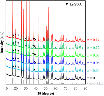
Powder XRD patterns of the LLZ-CaSb + xLi7SbO6 (x = 0–0.14) system were acquired after calcination at 950 °C (Fig. 1). The cubic garnet phase with the space group Ia![[3 with combining macron]](https://www.rsc.org/images/entities/char_0033_0304.gif) d appeared predominantly in all samples, in accordance with ICSD entry 182
d appeared predominantly in all samples, in accordance with ICSD entry 182![[thin space (1/6-em)]](https://www.rsc.org/images/entities/char_2009.gif) 312. Moreover, the intensity of the Li7SbO6-associated diffraction peak – conforming to ICSD entry 413
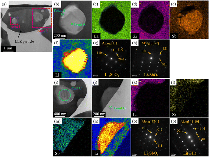
312. Moreover, the intensity of the Li7SbO6-associated diffraction peak – conforming to ICSD entry 413![[thin space (1/6-em)]](https://www.rsc.org/images/entities/char_2009.gif) 370 – increased with increasing x, especially at x values greater than 0.04 (see Fig. S1†). STEM-EDS images of the LLZ-CaSb + 0.08Li7SbO6 particles (Fig. 2) were analysed because they exhibited the highest sinterability among the samples, as described later. Two regions with different contrasts were observed in the LLZ-CaSb particles. Notably, the elemental maps (Fig. 2c–f and k–n) indicated the absence of La and Zr and the presence of Sb and Li in this region. The acquired electron diffraction patterns (Fig. 2g, h, and o; corresponding to Points A, B, and C in Fig. 2b and i) were assigned to monoclinic Li3SbO4 (P2/c(13)), monoclinic Li5SbO5 (C2/m(12)), and trigonal Li7SbO6 (R3(146)), respectively. Although the XRD results indicated that Li7SbO6 was present largely as a secondary phase, STEM analysis revealed a small number of different Li–Sb–O-type oxides. Moreover, the surface layer of the particles contained Li (Fig. 2j and n). The acquired electron diffraction pattern of the surface layer (Fig. 2p) was assigned to Li(OH) (tetragonal, P4/nmm(129)). In our previous study, this surface layer could not be confirmed through similar STEM observations of Ca–Bi-doped LLZ with Li–Bi–O sintering aids,29 implying that the surface Li(OH) layer was probably created via excessive Li addition. Notably, Li7SbO6 as well as Li3SbO4 and Li5SbO5, which were produced through the decomposition of Li7SbO6, was detected in the present study through STEM analysis of the Ca–Sb-doped LLZ and Li–Sb–O sintering aids. The decomposition of Li7SbO6 was initiated by the generation of Li2O, which easily reacted with humid air to form Li(OH); this functioned as a low-melting-point material that promoted the sintering of LLZ.36 Thus, sintering of the Ca–Sb-doped LLZ with Li–Sb–O sintering aids can be influenced by Li(OH).
370 – increased with increasing x, especially at x values greater than 0.04 (see Fig. S1†). STEM-EDS images of the LLZ-CaSb + 0.08Li7SbO6 particles (Fig. 2) were analysed because they exhibited the highest sinterability among the samples, as described later. Two regions with different contrasts were observed in the LLZ-CaSb particles. Notably, the elemental maps (Fig. 2c–f and k–n) indicated the absence of La and Zr and the presence of Sb and Li in this region. The acquired electron diffraction patterns (Fig. 2g, h, and o; corresponding to Points A, B, and C in Fig. 2b and i) were assigned to monoclinic Li3SbO4 (P2/c(13)), monoclinic Li5SbO5 (C2/m(12)), and trigonal Li7SbO6 (R3(146)), respectively. Although the XRD results indicated that Li7SbO6 was present largely as a secondary phase, STEM analysis revealed a small number of different Li–Sb–O-type oxides. Moreover, the surface layer of the particles contained Li (Fig. 2j and n). The acquired electron diffraction pattern of the surface layer (Fig. 2p) was assigned to Li(OH) (tetragonal, P4/nmm(129)). In our previous study, this surface layer could not be confirmed through similar STEM observations of Ca–Bi-doped LLZ with Li–Bi–O sintering aids,29 implying that the surface Li(OH) layer was probably created via excessive Li addition. Notably, Li7SbO6 as well as Li3SbO4 and Li5SbO5, which were produced through the decomposition of Li7SbO6, was detected in the present study through STEM analysis of the Ca–Sb-doped LLZ and Li–Sb–O sintering aids. The decomposition of Li7SbO6 was initiated by the generation of Li2O, which easily reacted with humid air to form Li(OH); this functioned as a low-melting-point material that promoted the sintering of LLZ.36 Thus, sintering of the Ca–Sb-doped LLZ with Li–Sb–O sintering aids can be influenced by Li(OH).
Sintering properties and characterisation of the LLZ-CaSb + xLi7SbO6 + Li3BO3 composite electrolyte
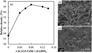
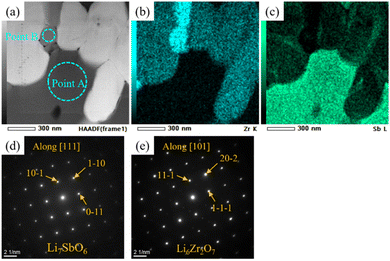
The manner in which the relative density of the sintered electrolytes depended on the sintering temperature was analysed, and SEM images of the fracture surfaces of samples with x = 0 and 0.08 were acquired (Fig. 3). At x = 0, the relative density of the specimen was low and numerous micropores were present. The relative density increased with increasing x, reaching a maximum value of 87% at x = 0.08. Notably, no large pores were present in the sample corresponding to x = 0.08, and an intergranular fracture was partially observed, suggesting the progress of sintering (Fig. 3c).Cross-sectional SEM-EDS images acquired after ion milling (Fig. 4) indicated that the LLZ-CaSb particles contained two differently coloured liquid-phase materials. Oxygen and boron were partially present in certain areas (black zones in Fig. 4b), whereas oxygen and antimony were present in other regions (grey zones in Fig. 4b). Additionally, the Sb compound was spread around the LLZ-CaSb particles, whereas Zr-rich areas were present between the LLZ-CaSb particles. A similar imaging analysis of the electrolytes with x = 0.04 and x = 0.14 (Fig. S2†) suggested that the Sb-containing liquid-phase region broadened as x increased, aggregating over a wide area at x = 0.14. In all the investigated compositions, boron was absent in the areas where antimony was present, suggesting that the two liquid phases were immiscible. Therefore, Sb likely aggregated owing to its wettability with respect to the B-containing liquid phase. A more comprehensive analysis was performed by STEM-EDS imaging of the locations where the Sb-containing liquid phase was present between the LLZ-CaSb particles (Fig. 5). The acquired diffraction patterns indicated that the Sb-containing liquid-phase region and the Zr-rich zone comprised Li7SbO6 (triclinic, P1(2)) and Li6Zr2O7 (monoclinic, C2/c(15)), respectively (Fig. 5d and e). STEM images were also obtained for the other parts where Sb was not detected between the LLZ-CaSb particles (Fig. 6). The images were expected to showcase the Li3BO3 added as a sintering aid; however, the diffraction patterns suggested that Li4B2O5 (orthorhombic, Pca21(29)) and Li3B11O18 (monoclinic, P21/a(21)) were present in the electrolyte (Fig. 6c and f). According to the Li2O–B2O3 phase diagram reported by Rousse et al. (Fig. S3†),37 Li4B2O5 has a eutectic composition and melts at a temperature (650 °C) lower than that of Li3BO3.38 Moreover, Li3B11O18 partially melts at 635 °C to form LiB3O5 and B2O3 liquid phases. The self-generation of this low-melting-point compound can potentially permit low-temperature sintering. XRD patterns of the LLZ-CaSb + xLi7SbO6 + Li3BO3 composite electrolytes (Fig. S4†) indicated that LiB3O5 was present in all the investigated samples (x = 0–0.14), with Li7SbO6 and La2Zr2O7 also detected at x ≥ 0.12. LiB3O5 was formed when Li3B11O18 decomposed and melted, as described above. (The detailed reaction scheme is presented later.) In essence, Li3BO3 transformed into a Li-lean composition.
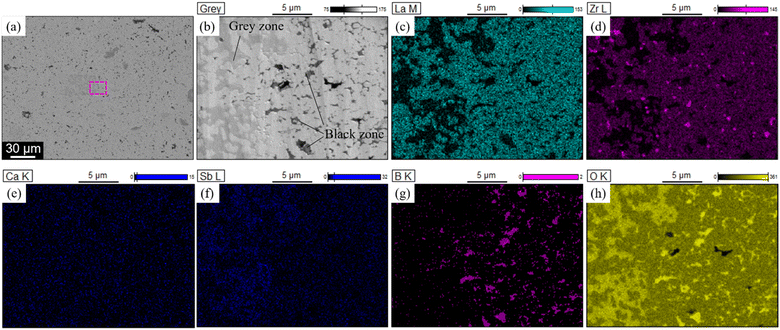 | ||
| Fig. 4 (a) Low- and (b) high-magnification SEM images of the LLZ-CaSb + 0.08Li7SbO6 + Li3BO3 composite electrolyte sintered at 750 °C. (c)–(h) EDS maps of the region marked by the pink square in (a). | ||
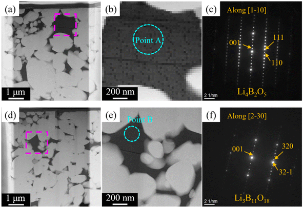 | ||
| Fig. 6 (a, b and d, e) HAADF-STEM images of the LLZ-CaSb + 0.08Li7SbO6 + Li3BO3 electrolyte sintered at 750 °C. Electron diffraction patterns of (c) Point A and (f) Point B, marked in (b) and (e). | ||
TMA was subsequently performed to clarify the sintering behaviour of the electrolytes (Fig. 7). A Li3BO3-free sample was also evaluated for comparison. The results indicated that all samples started expanding at ∼350 °C. This trend was not observed in our previous study on Ca–Bi-doped LLZ;28,29 therefore, this feature was evidently associated with the composition adopted in this study. Through DFT calculations, Gaultois et al. determined that Li7SbO6 and Li5SbO5 absorb CO2 at specific temperatures at PCO2 = 1 × 10⁴ Pa via the following routes:39
| Li7SbO6 + CO2 → Li5SbO5 + Li2CO3Tcarbonation = 630 °C, | (1) |
| Li5SbO5 + CO2 → Li3SbO4 + Li2CO3Tcarbonation = 458 °C. | (2) |
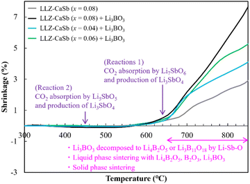 | ||
| Fig. 7 Temperature-dependent linear shrinkage of LLZ-CaSb + xLi7SbO6 (x = 0.04, 0.06, and 0.08) with and without the Li3BO3 composite pellets. | ||
Based on this information, the aforementioned volume expansion between 400 and 530 °C was attributed to the volume expansion induced by the CO2 adsorption of Li5SbO5. However, all samples of LLZ-CaSb (x = 0.04, 0.06, and 0.08) and Li3BO3 except LLZ-CaSb (x = 0.08) exhibited significant shrinkage at temperatures above ∼650 °C. Therefore, based on the results shown in Fig. 5 and 6, reactions (3)–(7) transpired between Li3BO3 and Li3SbO4, and contraction occurred owing to the melting of Li4B2O5 and Li3B11O18. According to the Materials Project database, the formation energy of Li–B–O-type oxides (Li3BO3, Li4B2O5, and Li3B11O18) is lower than that of Li–Sb–O-type oxides (Li7SbO6, Li5SbO5, and Li3SbO4). Li3B11O18 is the most stable compound among these oxides; therefore, Li3BO3 decomposes into Li3B11O18.
| Li3SbO4 + 2Li3BO3 → Li5SbO5 + Li4B2O5(l) | (3) |
| Li5SbO5 + 2Li3BO3 → Li7SbO6 + Li4B2O5(l) | (4) |
| 15Li3SbO4 + 11Li3BO3 → 15Li5SbO5 + Li3B11O18 | (5) |
| 15Li5SbO5 + 11Li3BO3 → 15Li7SbO6 + Li3B11O18 | (6) |
| Li3B11O18 → 3LiB3O5 + B2O3(l) | (7) |
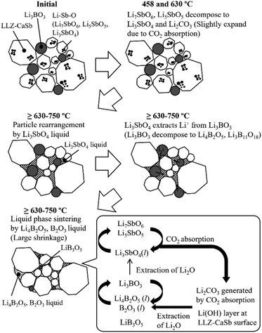
Li4B2O5, Li3B11O18, LiB3O5, and B2O3 have B–O–B bonds in their structures, which can help extract Li2O from LLZ.22 Consequently, Li4B2O5, Li3B11O18, LiB3O5, and B2O3 transform into Li3BO3, whereas LLZ forms an impurity phase of La2Zr2O7 during sintering. The formation of La2Zr2O7 was substantiated by the XRD patterns of the specimens with x ≥ 0.12 (Fig. S4†). LiB3O5 exhibited its diffraction peak because it existed as a solid, given its melting point of 834 °C; therefore, solid-phase LiB3O5 showed poor reactivity and did not permit Li2O extraction compared to the other compounds with B–O–B bonds. This was presumably due to the continuous occurrence of reactions (1)–(7) and the preferential reaction of Li4B2O5, Li3B11O18, and B2O3 with Li2CO3 produced continuously according to reactions (1) and (2). Additionally, one of the factors was the ability of the Li(OH) surface layer to prevent the direct reaction, as confirmed in Fig. 2. Reactions (3)–(6) suggest that for the reaction to proceed continuously, a sufficient amount of Li3SbO4 is required to extract Li2O from Li3BO3. Notably, the slope of the shrinkage profiles at temperatures above 650 °C was relatively well maintained up to high temperatures as x increased (Fig. 7). For the specimens with x = 0.04 and 0.06, the slope after the rapid contraction above 650 °C subsided was similar to that of the Li3BO3-free sample; therefore, the LLZ-CaSb particles shrank because of progress in the solid-phase sintering. However, for the sample with x = 0.08, the slope at temperatures above 650 °C was constant. Therefore, at x = 0.08, the Li4B2O5 and B2O3 liquid phases were continuously generated to promote reactions (3)–(7); however, at x ≤ 0.06, the amount of Li3SbO4 was insufficient. These findings indicate that low-temperature sintering was achieved owing to the continuous occurrence of (i) the decomposition of the Li–Sb–O compounds by CO2 absorption and (ii) the formation of the Li4B2O5 and B2O3 liquid phases via the reaction between the decomposition product and Li3BO3. As explained in Fig. S2† discussion, the Li–Sb–O and (Li)–B–O liquid phases were incompatible. Therefore, when x ≥ 0.12, a large amount of the L–Sb–O liquid phase inhibited the wetting of the (Li)–B–O liquid phase. Additionally, owing to the presence of a large amount of the Li4B2O5 and B2O3 liquid phases at x ≥ 0.12, the Li2O derived from reactions (1) and (2) and the Li(OH) surface layer was insufficient, yielding La2Zr2O7. Therefore, the sinterability diminished at x ≥ 0.12. The sintering mechanism and scheme of the reactions occurring at ∼650 °C are presented in Fig. 8.
Electrical properties of the LLZ-CaSb + xLi7SbO6 + Li3BO3 composite electrolyte
Nyquist plots of the prepared electrolytes were acquired at 25 °C (Fig. S5†). Two distinct semicircles were observed in the high- and intermediate-frequency regions, which represented the bulk resistance and grain boundary resistance, respectively. The appearance of a tail in the low-frequency region suggested that the electrode blocked mobile Li ions. As x increased, both the bulk resistance and grain boundary resistance tended to decrease, and the magnitude of the grain boundary resistance was reduced. The lowered bulk resistance was due to the reduced tortuosity at a higher relative density (Fig. 3). Additionally, the progress in sintering contributed to the grain boundary resistance. Furthermore, sintering improved the interparticle contact and reduced the number of grain boundaries. A simple equivalent circuit expressed as (Re)(Rb//CPEb)(Rgb//CPEgb)(CPEel) was used to fit the acquired data (solid profiles in Fig. S5†); here, R is the resistance; CPE is the constant phase element; and the subscripts b, gb, and el represent the contributions from the bulk, grain boundary, and electrode, respectively. The total Li-ion conductivity σtotal was calculated using Re, Rb, Rgb, the electrode area S, and sample thickness t (Fig. 9a). Similar to the relative density, σtotal increased with increasing x and reached a maximum value (3.1 × 10⁻⁴ S cm−1) at x = 0.08; this value is equivalent to that obtained previously by our group for the Li6.5La2.9Ca0.1Zr1.4Bi0.6O12 and Li3BO3 system at a sintering temperature of 750 °C.28 Arrhenius plots of the total Li-ion conductivity, bulk conductivity, and grain boundary conductivity were subsequently constructed (Fig. S6a–c,† respectively). The activation energies were calculated from the slopes of the lines, and the changes in bulk conductivity with x were analysed (Fig. 9b). The sample with x = 0.08 exhibited maximal bulk ionic conductivity and minimal activation energy Etotal. This was caused more by the decrease in the grain boundary activation energy Egb than by the decrease in the bulk activation energy Ebulk. At x ≤ 0.08, the progress in sintering presumably enabled smooth ion transport at the grain boundaries. However, the Egb values for the samples with x ≥ 0.12 were large despite them having the densities of the x = 0.04 and 0.06 specimens. Therefore, the grain boundary part of the electrolytes with x = 0.08 and 0.14 was subjected to STEM analysis to clarify this issue (Fig. 10). At x = 0.08, the grain boundary and bulk had the same contrast; however, at x = 0.14, a portion with a different contrast appeared at the grain boundary. This different-contrast area was poor in La and Zr but rich in Sb. The composition of the grain boundary differed significantly from that of LLZ at x = 0.14, which presumably increased the activation energy of the grain boundary in the region of the samples with x ≥ 0.12. This compositional deviation was evidently caused by an increase in the Li–Sb–O liquid phase that entered between the LLZ particles, as illustrated in Fig. S7.†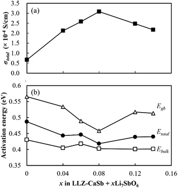 | ||
| Fig. 9 Effects of x on the (a) total ionic conductivity at 25 °C and (b) activation energy of the LLZ-CaSb + xLi7SbO6 + Li3BO3 composite electrolytes. | ||
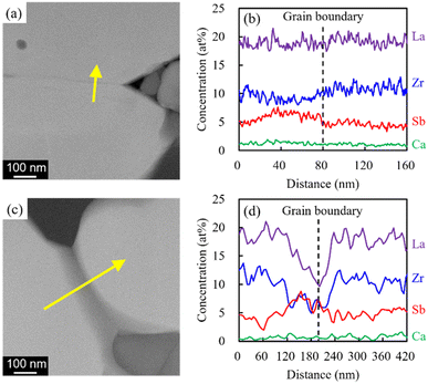 | ||
| Fig. 10 HAADF images and changes in atomic concentration across the yellow line around the necking region for the electrolytes with (a) and (b) x = 0.08 and (c) and (d) x = 0.14. | ||
CV profiles were acquired to evaluate the electrochemical window (Fig. 11). The redox peaks appearing at ∼0.2 V (vs. Li/Li+) were evidently due to the alloying of Li and Au and the stripping/plating of Li, as indicated by Yan et al., who reported the alloying of Au and Li at 0.2 V.40 Kundu et al. suggested that Li7SbO6 can undergo lithiation and de-lithiation at 0.8 V.41 However, the redox peak at ∼0.8 V was not exhibited by the electrolyte reported herein. This was likely due to the presence of Li metal, which may have eliminated the need for using the Li from Li7SbO6, and the remarkably low volume of Li7SbO6 (∼3.6 vol%), which prevented it from percolating, and consequently, functioning. Additionally, in the high-voltage range, no redox peaks were observed up to ∼5.0 V. This tendency was also exhibited by other LLZ-CaSb + xLi7SbO6 (x = 0.04, 0.06, 0.12, and 0.14) + Li3BO3 composites (Fig. S8†). Overall, these results suggest that the LLZ-CaSb + xLi7SbO6 + Li3BO3 electrolyte exhibited a wide electrochemical window.
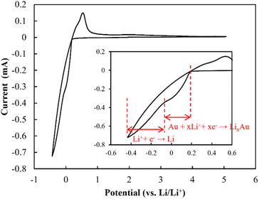 | ||
| Fig. 11 Cyclic voltammetry profiles of the Au|LLZ-CaSb + 0.08Li7SbO6 + Li3BO3|Li cell at a scan rate of 1 mV s−1. | ||
Long-term Li plating/stripping tests conducted at 0.05 mA cm−2 (Fig. 12) indicated that the plating/stripping could be performed for 150 cycles, and that the electrolyte was stable against Li metal. A comparison with previously reported Li plating/stripping test results (Table S1†)25,42–48 suggested that the use of a low sintering temperature in the present study (750 °C) led to the same level of stability against Li plating/stripping as that of electrolytes sintered at higher temperatures. In addition to chemical stability, the wettability against Li metal is another crucial factor in achieving stable plating/stripping. Therefore, Li metal melting on pristine and Au-coated electrolyte specimens was analysed (Fig. S9†), and the results demonstrated the superior wettability of the Au-coated sample. This finding is consistent with previously reported alloying of Au with Li to improve wettability and reduce the interfacial resistance.44,46
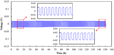 | ||
| Fig. 12 Li plating/stripping performance of the Li|Au|LLZ-CaSb + 0.08Li7SbO6|Au|Li sample at a current density of 0.05 mA cm−2. | ||
Characteristics of the co-sintered bulk-type all-solid-state battery
SEM-EDS images of the cathode layer were acquired, and cyclic charge–discharge tests were conducted at 25 °C (Fig. 13). The elemental maps showed a clear interface between LiCoO2 and LLZ-CaSb, indicating that no impurity phases were formed. The O map suggested that the relative density was 93%, and the interfaces between LiCoO2 and LLZ-CaSb particles were in close contact. Additionally, the initial discharge capacity was 120.7 mA h g−1, and the cell could be charged and discharged for 60 cycles. Furthermore, the ASSB maintained a stable capacity over a long duration (Fig. 14a), with the discharge capacity retention rate after 60 cycles being 98.6%. Table 1 lists the battery performance, manufacturing methods, and evaluation conditions employed in the present study and in previous investigations on the cycling characteristics of bulk-type ASSBs.14,15,28,49–51 Our previously reported system exhibited a noteworthy discharge capacity and cycling performance, with the battery comprising Li6.5La2.9Ca0.1Zr0.4Bi0.6O12 (LLZ-CaBi) and Li3BO3 exhibiting a retention rate of 92.8% after 40 cycles at 60 °C.28 However, the electrolyte reported herein outperforms our previously reported system in terms of cycling behaviour; one of the reasons for this is the stability of LLZ-CaSb + 0.08Li7SbO6 against Li metal, which eliminates the need for a polyethylene-oxide (PEO)-based electrolyte in the buffer layer. Typically, PEO-based electrolytes are not stable against Li metal for prolonged durations, and their interfacial resistance increases.28 To corroborate this result, the change in resistance after the first charge and after 60 charging cycles was monitored (Fig. 14b). The semicircular arc resistance that appeared at frequencies above 104 Hz increased after cycling. Nyquist plots were constructed after forming Ag electrodes on the electrolyte and then bonding Li metal to both sides of the same sample (Fig. S9†). In the profile of the sample with Li metal as the electrode, a semicircular arc was observed, which did not appear initially. Therefore, the resistance corresponding to frequencies ≥ 19![[thin space (1/6-em)]](https://www.rsc.org/images/entities/char_2009.gif) 952 Hz was considered to be the grain boundary resistance of LLZ, and that corresponding to 6.3–19952 Hz was deemed the interfacial resistance between LLZ and Li metal. These results indicate that the increase in the grain boundary resistance of LLZ caused deterioration. This was presumably due to the change in the volume of LiCoO2 during charging and discharging. Further research will help in shining more light on this matter.
952 Hz was considered to be the grain boundary resistance of LLZ, and that corresponding to 6.3–19952 Hz was deemed the interfacial resistance between LLZ and Li metal. These results indicate that the increase in the grain boundary resistance of LLZ caused deterioration. This was presumably due to the change in the volume of LiCoO2 during charging and discharging. Further research will help in shining more light on this matter.
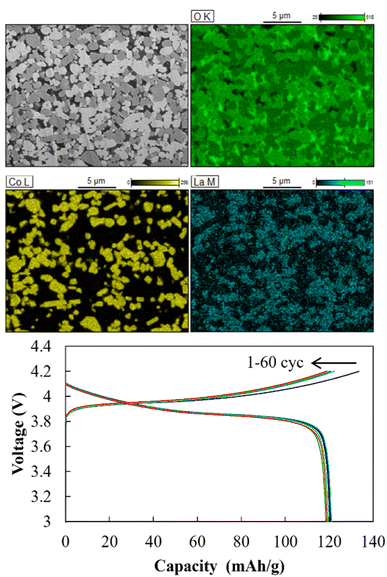 | ||
| Fig. 13 Cross-sectional SEM-EDS images of the cathode layer in the Li|LLZ-CaSb + 0.08Li7SbO6|LiCoO2 + LLZ-CaSb + 0.08Li7SbO6 + Li3BO3 ASSB, and charge–discharge curves acquired at 0.1C and 25 °C. | ||
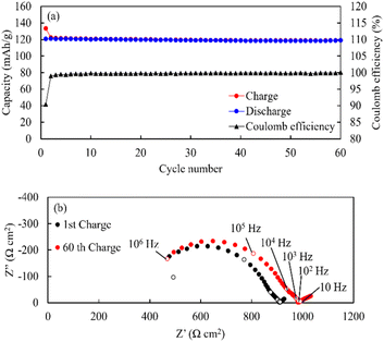 | ||
| Fig. 14 (a) Long-term cycling behaviour, rate performance data, and (b) Nyquist plots of the Li|LLZ-CaSb + 0.08Li7SbO6|LiCoO2 + LLZ-CaSb + 0.08Li7SbO6 + Li3BO3 ASSB obtained at 0.1C and 25 °C. | ||
| Reference | Cathode composition | Cathode sintering temperature (°C) | Sintering technique | Voltage range (V) | Rate (C) | Operating temperature (°C) | Initial discharge capacity (mAh g−1) | Number of cycles | Capacity retention rate |
|---|---|---|---|---|---|---|---|---|---|
| Han et al. (2018)49 | LiCoO2 + Li2.3C0.7B0.3O3 + LLZ | 700 | Conventional sintering | 3.0–4.05 | 0.05 | 25 | 94 | 100 | 88.3% |
| Wang et al. (2019)14 | LiNi0.6Mn0.2Co0.2 + Li3BO3 + LLZ-Ta | 700 | Conventional sintering | 3.0–4.2 | 0.05 | 25 | 106 | 30 | 70% |
| Feng et al. (2020)50 | LiCoO2 + Li2.985B0.05OCl + LLZ | 400 | Hot pressing | 3.0–4.1 | 0.05 | 25 | 71.3 | 20 | 70.1% |
| Guo et al. (2021)15 | LiCoO2 + γ-Al2O3 + LLZ-Nb | 850 | Conventional sintering | 2.8–4.15 | 0.2 | 100 | 93.6 | 16 | 92% |
| Akimoto et al. (2023)51 | LiNi0.6Mn0.2Co0.2 + LLZ-Ta | 550 | Hot pressing | 2.5–4.2 | 0.01 | 25 | 125 | 26 | 85.6% |
| Hayashi et al. (2023)28 | LiCoO2 + Li3BO3 + LLZ-CaBi | 750 | Conventional sintering | 3.0–4.2 | 0.1 | 60 | 100 | 40 | 92.8% |
| Present study | LiCoO2 + Li3BO3 + Li7SbO6+ LLZ-CaSb | 750 | Conventional sintering | 3.0–4.2 | 0.1 | 25 | 120.7 | 60 | 98.6% |
Reducing the interfacial resistance between the cathode and LLZ is an important issue in oxide-based ASSB development, as reported by Kim et al.,52 who achieved a remarkably low resistance of 62 Ω cm2 by adapting a process to directly synthesise LiCoO2 from infiltration metal salts in a porous LLZ scaffold. Zheng et al. reported that the interfacial resistance between the cathode and LLZ appeared at 1–150 Hz.53 For the battery developed in the present study, the interfacial resistance after the first charge was 9.1 Ω cm2; this is the lowest value among similar previously reported systems. This implies that smooth ion transport can be realised at the interface, and a high-output battery can be developed. Therefore, rate performance was evaluated using batteries with the same configuration (Fig. S10†). The results indicated that charging and discharging could be repeated stably at 0.2C and 0.3C as well as at 0.1C. Furthermore, owing to its stability, the ASSB was expected to function at temperatures unconducive to traditional LIB operation. To substantiate this proposition, the charge–discharge properties were analysed at different operating temperatures (−25, −1, 70, and 120 °C; Fig. S11†). The results indicated that cyclic operation was possible at all the operating temperatures, although the capacity tended to decrease with decreasing operating temperature. To our knowledge, this is the first report on an ASSB with an LLZ electrolyte that can operate over a considerably wide temperature range, although several systems have been reported to operate at temperatures above 50 °C.15,18,54–58 This is because of the high battery resistance caused by the insufficient density of the cathode layer or the use of a large amount of a low-ionic-conductivity sintering aid. The electrolyte developed in this study enables densification of the composite cathode and exhibits high ionic conductivity even when sintered at low temperatures. Therefore, the LLZ reported herein is a stepping stone for the realisation of robust batteries that can operate in harsh environments.
Conclusions
The Li6.5(La2.925Ca0.075)(Zr1.425Sb0.575)O12 + xLi7SbO6 + Li3BO3 composite electrolyte sintered at a low temperature was found to be suitable for achieving a high relative density, high lithium-ion conductivity, and wide electrochemical potential. A relative density of 87% and conductivity of 3.1 × 10⁻⁴ S cm−1 @ 25 °C were achieved as optimal values by the system sintered at 750 °C. Low-temperature sintering was realised by liquid-phase sintering with low-melting-point (Li)–B–O liquid phases (Li4B2O5 and B2O3) produced by the reaction between Li3SbO4 and Li3BO3, with the former generated when Li7SbO6 absorbed CO2. The (Li)–B–O liquid phase extracted Li2O from LLZ-CaSb to form an impurity phase; this was subsequently impaired by the Li2CO3 generated when Li7SbO6 absorbed CO2 and the Li(OH) layer produced on the LLZ-CaSb particles during the synthesis. When excess Li7SbO6 was added, the aggregated Li7SbO6 liquid phase entered between the LLZ-CaSb particles and obstructed the Li-ion motion, thereby increasing the grain boundary activation energy. Therefore, optimal performance was achieved at x = 0.08. Additionally, the electrolyte operated over a wide electrochemical window (>5 V vs. Li/Li+), allowing direct contact with Li metal. Therefore, the developed electrolyte can be used as a cathode layer, separator, and anode layer. The bulk-type ASSB fabricated by co-sintering exhibited outstanding charge–discharge performance. The new material reported herein shows considerable promise for use in ASSBs. Moreover, the new concept described herein can be a powerful tool for reducing the sintering temperature, because low-melting-point materials that react with LLZ and transform into high-melting-point materials can be used for liquid-phase sintering.Author contributions
Naohiro Hayashi: conceptualisation; investigation; writing – original draft preparation. Ken Watanabe: formal analysis; supervision; writing – review & editing. Kengo Shimanoe: formal analysis; writing – review & editing.Conflicts of interest
There are no conflicts to declare.References
- J.-M. Tarascon and M. Armand, Issues and challenges facing rechargeable lithium batteries, Nature, 2001, 414, 359–367 CrossRef CAS PubMed.
- M. Amand and J.-M. Tarascon, Building better batteries, Nature, 2008, 451, 652–657 CrossRef PubMed.
- Q. Wang, P. Ping, X. Zhao, G. Chu, J. Sun and C. Chen, Thermal runway caused fire and explosion of lithium ion battery, J. Power Sources, 2012, 208, 210–224 CrossRef CAS.
- Z. Gao, H. Sun, L. Fu, F. Ye, Y. Zhang, W. Luo and Y. Huang, All-solid-state batteries: Promises, challenges, and recent progress of inorganic solid-state electrolytes for all-solid-state lithium batteries, Adv. Mater., 2018, 30, 1870122 CrossRef.
- Y. Liu, Q. Sun, Y. Zhao, B. Wang, P. Kaghazchi, K. R. Adair, R. Li, C. Zhang, J. Liu, L.-Y. Kuo, Y. Hu, T.-K. Sham, L. Zhang, R. Yang, S. Lu, X. Song and X. Sun, Stabilizing the interface of NASICON solid electrolyte against Li metal with atomic layer deposition, ACS Appl. Mater. Interfaces, 2018, 10, 31240–31248 CrossRef CAS PubMed.
- R. Murugan, V. Thangadurai and W. Weppner, Fast lithium ion conduction in garnet-type Li7La3Zr2O12, Angew. Chem., Int. Ed., 2007, 46, 7778–7781 CrossRef CAS PubMed.
- Q. Liu, Z. Geng, C. Han, Y. Fu, S. Li, Y.-b. He, F. Kang and B. Li, Challenges and perspectives of garnet solid electrolytes for all solid-state lithium batteries, J. Power Sources, 2018, 389, 120–134 CrossRef CAS.
- Y. Chen, J. Qian, X. Hu, Y. Ma, Y. Li, T. Xue, T. Yu, L. Li, F. Wu and R. Chen, Constructing a uniform and stable mixed conductive layer to stabilize the solid-state electrolyte/Li interface by cold bonding at mild conditions, Adv. Mater., 2023, 35, 2212096 CrossRef CAS PubMed.
- Y. Zhang, X. Gao, Z. Tang, Y. Mei, X. Xiang and J. Deng, Study on the suppression lithium dendrites based on solid electrolyte Li7La3Zr2O12 with annealing treatment of Al interlayer, J. Alloys Compd., 2022, 904, 163908 CrossRef CAS.
- H. Koshikawa, S. Matsuda, K. Kamiya, M. Miyayama, Y. Kubo, K. Uosaki, K. Hashimoto and S. Nakanishi, Electrochemical impedance analysis of the Li/Au-Li7La3Zr2O12 interface during Li dissolution/deposition cycles: Effect of pre-coating Li7La3Zr2O12 with Au, J. Electroanal. Chem., 2019, 835, 143–149 CrossRef CAS.
- K. Fu, Y. Gong, B. Liu, Y. Zhu, S. Xu, Y. Yao, W. Luo, C. Wang, S. D. Lacey, J. Dai, Y. Chen, Y. Mo, E. Wachsman and L. Hu, Toward garnet electrolyte-based Li metal batteries: An ultrathin, highly effective, artificial solid-state electrolyte/metallic Li interface, Sci. Adv., 2017, 3, 1601659 CrossRef PubMed.
- K. H. Kim, Y. Iriyama, K. Yamamoto, S. Kumazaki, T. Asaka, K. Tanabe, C. A. J. Fisher, T. Hirayama, R. Murugan and Z. Ogumi, Characterization of the interface between LiCoO2 and Li7La3Zr2O12 in an all-solid-state rechargeable lithium battery, J. Power Sources, 2011, 196, 764–767 CrossRef CAS.
- G. Vardar, W. J. Bowman, Q. Lu, J. Wang, R. J. Chater, A. Aguadero, R. Seibert, J. Terry, A. Hunt, I. Waluyo, D. D. Fong, A. Jarry, E. J. Crumlin, S. L. Hellstrom, Y.-M. Chiang and B. Yildiz, Structure, chemistry, and charge transfer resistance of the interface between Li7La3Zr2O12 electrolyte and LiCoO2 cathode, Chem. Mater., 2018, 30, 6259–6276 CrossRef CAS.
- D. Wang, Q. Sun, J. Luo, J. Liang, Y. Sun, R. Li, K. Adair, L. Zhang, R. Yang, S. Lu, H. Huang and X. Sun, Mitigating the interfacial degradation in cathodes for high-performance oxide-based solid-state lithium batteries, ACS Appl. Mater. Interfaces, 2019, 11, 4954–4961 CrossRef CAS PubMed.
- H. Guo, F. Shen, W. Guo, D. Zeng, Y. Yin and X. Han, LiCoO2/Li6.75La3Zr1.75Nb0.25O12 interface modification enables all-solid-state battery, Mater. Lett., 2021, 301, 130302 CrossRef CAS.
- A. Sharafi, H. M. Meyer, J. Nanda, J. Wolfenstine and J. Sakamoto, Characterizing the Li–Li7La3Zr2O12 interface stability and kinetics as a function of temperature and current density, J. Power Sources, 2016, 302, 135–139 CrossRef CAS.
- R. H. Basappa, T. Ito, T. Morimura, R. Bekarevich, K. Mitsuishi and H. Yamada, Grain boundary modification to suppress lithium penetration through garnet-type solid electrolyte, J. Power Sources, 2017, 363, 145–152 CrossRef.
- M. Ihrig, M. Finsterbusch, C.-L. Tsai, A. M. Laptev, C.-H. Tu, M. Bram, Y. J. Sohn, R. Ye, S. Sevinc, S.-K. Lin, D. Fattakhova-Rohlfing and O. Guillon, Low temperature sintering of fully inorganic all-solid-state batteries – Impact of interfaces on full cell performance, J. Power Sources, 2021, 482, 228905 CrossRef CAS.
- M. Botros, R. Djenadic, O. Clements, M. Moller and H. Hahn, Field assisted sintering of fine-grained Li7-3xLa3Zr2AlxO12 solid electrolyte and the influence of the microstructure on the electrochemical performance, J. Power Sources, 2016, 309, 108–115 CrossRef CAS.
- N. Janani, C. Deviannapoorani, L. Dhivya and R. Murugan, Influence of sintering additives on densification and Li+ conductivity of Al doped Li7La3Zr2O12 lithium garnet, RSC Adv., 2014, 4, 51228–51238 RSC.
- N. C. Rosero-Navarro, A. Miura, M. Higuchi and K. Tadanaga, Optimization of Al2O3 and Li3BO3 content as sintering additives of Li7-xLa2.95Ca0.05ZrTaO12 at low temperature, J. Electron. Mater., 2017, 46, 497–501 CrossRef CAS.
- R. Takano, K. Tadanaga, A. Hayashi and M. Tatsumisago, Low temperature synthesis of Al-doped Li7La3Zr2O12 solid electrolyte by a sol–gel process, Solid State Ionics, 2014, 255, 104–107 CrossRef CAS.
- L. C. Zhang, J. F. Yang, Y. X. Gao, X. P. Wang, Q. F. Fang and C. H. Chen, Influence of Li3BO3 additives on the Li+ conductivity and stability of Ca/Ta-substituted Li6.55(La2.95Ca0.05)(Zr1.5Ta0.5)O12 electrolytes, J. Power Sources, 2017, 355, 69–73 CrossRef CAS.
- S. Ohta, J. Seki, Y. Yagi, Y. Kihira, T. Tani and T. Asaoka, Co-sinterable lithium garnet-type oxide electrolyte with cathode for all-solid-state lithium ion battery, J. Power Sources, 2014, 265, 40–44 CrossRef CAS.
- B. Xu, W. Li, H. Duan, H. Wang, Y. Guo, H. Li and H. Liu, Li3PO4-added garnet-type Li6.5La3Zr1.5Ta0.5O12 for Li-dendrite suppression, J. Power Sources, 2017, 354, 68–73 CrossRef CAS.
- P. Wakudkar and A. V. Deshpande, Effect of Li4SiO4 addition in Li6.22Al0.16La3Zr1.7Ta0.3O12 garnet type solid electrolyte for lithium ion battery application, Ceram. Int., 2019, 45, 20113–20120 CrossRef CAS.
- K. Watanabe, A. Tashiro, Y. Ichinose, S. Takeno, K. Suematsu, K. Mitsuishi and K. Shimanoe, Lowering the sintering temperature of Li7La3Zr2O12 electrolyte for co-fired all-solid-state batteries via partial Bi substitution and precise control of compositional deviation, J. Ceram. Soc. Jpn., 2022, 130, 416–423 CrossRef CAS.
- N. Hayashi, K. Watanabe and K. Shimanoe, Low-temperature sintering characteristics and electrical properties of Ca- and Bi-doped Li7La3Zr2O12 electrolyte containing Li3BO3 additive, J. Mater. Chem. A, 2023, 11, 2042–2053 RSC.
- N. Hayashi, K. Watanabe, T. Ohnishi, K. Takada and K. Shimanoe, Impact of intentional composition tuning on the sintering properties of Ca-Bi co-doped Li7La3Zr2O12 for co-fired solid-state batteries, J. Mater. Chem. A, 2023, 11, 15681–15690 RSC.
- Y. Zhu, J. G. Connell, S. Tepavcevic, P. Zapol, R. Garcia-Mendez, N. J. Taylor, J. Sakamoto, B. J. Ingram, L. A. Curtiss, J. W. Freeland, D. D. Fong and N. M. Markovic, Dopant-dependent stability of garnet solid electrolyte interfaces with lithium metal, Adv. Energy Mater., 2019, 9, 1803440 CrossRef.
- H. Nemori, Y. Matsuda, S. Mitsuoka, M. Matsui, O. Yamamoto, Y. Takeda and N. Imanishi, Stability of garnet-type solid electrolyte LixLa2A2-yByO12 (A = Nb or Ta, B = Sc or Zr), Solid State Ionics, 2015, 282, 7–12 CrossRef CAS.
- M. Nakayama, M. Kotobuki, H. Munakata, M. Nogami and K. Kanamura, First-principles density functional calculation of electrochemical stability of fast Li ion conducting garnet-type oxides, Phys. Chem. Chem. Phys., 2012, 14, 10008–10014 RSC.
- K.-H. Sun, Fundamental condition of glass formation, J. Am. Ceram. Soc., 1947, 30, 277–281 CrossRef CAS.
- L. J. Miara, W. D. Richards, Y. E. Wang and G. Ceder, First-principles studies on cation dopants and electrolyte|cathode interphases for lithium garnets, Chem. Mater., 2015, 27, 4040–4047 CrossRef CAS.
- X. Li, R. Li, S. Chu, K. Liao, R. Cai, W. Zhou and Z. Shao, Rational design of strontium antimony co-doped Li7La3Zr2O12 electrolyte membrane for solid-state lithium batteries, J. Alloys Compd., 2019, 794, 347–357 CrossRef CAS.
- H. Yamada, T. Ito, T. Nakamura, R. Bekarevich, K. Mitsuishi, S. P. Kammampata and V. Thangadurai, High cathode loading and low-temperature operating garnet-based all-solid-state lithium batteries – Material/process/architecture optimization and understanding of cell failure, Small, 2023, 19, 2301904 CrossRef CAS PubMed.
- G. Rousse, B. Baptiste and G. Lelong, Crystal structure of Li6B4O9 and Li3B11O18, and application of the dimensional reduction formalism to lithium borates, Inorg. Chem., 2014, 53, 6034–6041 CrossRef CAS PubMed.
- B. S. R. Sastry and F. A. Hummel, Studies in lithium oxide systems: I, Li2O B2O3–B2O3, J. Am. Ceram. Soc., 1958, 41, 7–17 CrossRef CAS.
- M. W. Gaultois, M. T. Dunstan, A. W. Bateson, M. S. C. Chan and C. P. Grey, Screening and characterization of ternary oxides for high-temperature carbon capture, Chem. Mater., 2018, 30, 2535–2543 CrossRef CAS.
- K. Yan, Z. Lu, H.-W. Lee, F. Xiong, P.-C. Hsu, Y. Li, J. Zhao, S. Chu and Y. Cui, Selective deposition and stable encapsulation of lithium through heterogeneous seeded growth, Nat. Energy, 2016, 1, 16010 CrossRef CAS.
- M. Kundu, S. Mahanty and R. N. Basu, Lithium hexaoxo antimonate as an anode for lithium-ion battery, Nanomater. Energ, 2012, 1, 51–56 CrossRef CAS.
- X. Huang, Y. Lu, H. Guo, Z. Song, T. Xiu, M. E. Badding and Z. Wen, None-mother-powder method to prepare dense Li-garnet solid electrolytes with high critical current density, ACS Appl. Energy Mater., 2018, 1, 5355–5365 CAS.
- S. Song, B. Chen, Y. Ruan, J. Sun, L. Yu, Y. Wang and J. Thokchom, Gd-doped Li7La3Zr2O12 garnet-type solid electrolytes for all-solid-state Li-Ion batteries, Electrochim. Acta, 2018, 270, 501–508 CrossRef CAS.
- G. V. Alexander, S. Patra, S. V. S. Raj, M. K. Sugumar, M. M. U. Din and R. Murugan, Electrodes-electrolyte interfacial engineering for realizing room temperature lithium metal battery based on garnet structured solid fast Li+ conductors, J. Power Sources, 2018, 396, 764–773 CrossRef CAS.
- M. S. Indu, G. V. Alexander, C. Deviannapoorani and R. Murugan, Realization of room temperature lithium metal battery with high Li+ conductive lithium garnet solid electrolyte, Ceram. Int., 2019, 45, 22610–22616 CrossRef.
- H. Koshikawa, S. Matsuda, K. Kamiya, M. Miyayama, Y. Kubo, K. Uosaki, K. Hashimoto and S. Nakanishi, Electrochemical impedance analysis of the Li/Au-Li7La3Zr2O12 interface during Li dissolution/deposition cycles: Effect of pre-coating Li7La3Zr2O12 with Au, J. Electroanal. Chem., 2019, 835, 143–149 CrossRef CAS.
- J. Su, X. Huang, Z. Song, T. Xiu, M. E. Badding, J. Jin and Z. Wen, Overcoming the abnormal grain growth in Ga-doped Li7La3Zr2O12 to enhance the electrochemical stability against Li metal, Ceram. Int., 2019, 45, 14991–14996 CrossRef CAS.
- B. Dong, S. R. Yeandel, P. Goddard and P. R. Slater, Combined experimental and computational study of Ce-doped La3Zr2Li7O12 garnet solid-state electrolyte, Chem. Mater., 2020, 32, 215–223 CrossRef CAS.
- F. Han, J. Yue, C. Chen, N. Zhao, X. Fan, Z. Ma, T. Gao, F. Wang, X. Guo and C. Wang, Interphase engineering enabled all-ceramic lithium battery, Joule, 2018, 2, 497–508 CrossRef CAS.
- W. Feng, Z. Lai, X. Dong, P. Li, Y. Wang and Y. Xia, Garnet-based all-ceramic lithium battery enabled by Li2.985B0.005OCl solder, iScience, 2020, 23, 101071 CrossRef CAS PubMed.
- J. Akimoto, T. Akao and K. Kataoka, Low-temperature fabrication of bulk-type all-solid-state lithium-ion battery utilizing nanosized garnet solid electrolytes, Small, 2023, 19, 2301617 CrossRef CAS PubMed.
- K. J. Kim and J. L. M. Rupp, All ceramic cathode composite design and manufacturing towards low interfacial resistance for garnet-based solid-state lithium batteries, Energy Environ. Sci., 2020, 13, 4930–4945 RSC.
- C. Zheng, S. Tang, F. Wen, J. Peng, W. Yang, Z. Lv, Y. Wu, W. Tang, Z. Gong and Y. Yang, Reinforced cathode-garnet interface for high-capacity all-solid-state batteries, Mater. Futures, 2022, 1, 045103 CrossRef.
- E. J. Cheng, Y. Kushida, T. Abe and K. Kanamura, Degradation mechanism of all-solid-state Li-metal batteries studied by electrochemical impedance spectroscopy, ACS Appl. Mater. Interfaces, 2022, 14, 40881–40889 CrossRef CAS PubMed.
- Y. Jiang, X. Zhu and W. Lai, Three electrodes analysis of a 3V-class all-solid-state lithium-ion battery based on garnet-type solid electrolyte Li6.4La3Zr1.4Ta0.6O12, J. Power Sources, 2022, 529, 231278 CrossRef CAS.
- E. II’ina, S. Pershina, B. Antonov and A. Pankratov, Impact of Li3BO3 addition on solid electrode-solid electrolyte interface in all-solid-state batteries, Materials, 2021, 14, 7099 CrossRef PubMed.
- K. Park, B.-C. Yu, J.-W. Jung, Y. Li, W. Zhou, H. Gao, S. Son and J. B. Goodenough, Electrochemical nature of the cathode interface for a solid-state lithium-ion battery: Interface between LiCoO2 and garnet-Li7La3Zr2O12, Chem. Mater., 2016, 28, 8051–8059 CrossRef CAS.
- M. Shoji, H. Munakata and K. Kanamura, Fabrication of all-solid-state lithium-ion cells using three-dimensionally structured solid electrolyte Li7La3Zr2O12 pellets, Front. Energy Res., 2016, 4, 32 Search PubMed.
Footnote |
| † Electronic supplementary information (ESI) available. See DOI: https://doi.org/10.1039/d3ta06747e |
| This journal is © The Royal Society of Chemistry 2024 |

