 Open Access Article
Zirconium-metal–organic framework@activated carbon composites for prevention of secondary emission of nerve agents†
Cristina
Perona‡
 a,
Emilio
Borrego-Marin‡
 a,
Pedro
Delgado
a,
Rebecca
Vismara
a,
Pedro
Delgado
a,
Rebecca
Vismara
 a,
Carmen R.
Maldonado
 a,
Elisa
Barea
 a,
Teresa J.
Bandosz
 b and
Jorge A. R.
Navarro
 *a
*a
aDepartamento de Química Inorgánica, Universidad de Granada, Av. Fuentenueva S/N, 18071, Granada, Spain. E-mail: jarn@ugr.es
bDepartment of Chemistry, CUNY, New York, USA
First published on 4th December 2023
Abstract
We have studied the formation of core–shell hybrid metal–organic framework@activated carbon sphere (MOF@AC) adsorbents, by means of a layer-by-layer (LBL) growth method of MOFs on shaped AC materials. The hybrid MOF@AC materials are useful for preventing the secondary emission problems of chemical warfare agent protective filters. Mesopores on AC materials facilitate carbon surface oxidation and a subsequent MOF growth, allowing Zr6O4(OH)4(benzene-1,4-dicarboxylate-2-X)6 (X = H, UiO-66; X = NH2, UiO-66-NH2) thin film formation. By contrast, microporous spheres do not allow a significant MOF layer growth. The MOF@AC hybrids are able to capture the G-type nerve agent surrogate, diisopropylfluorophosphate (DIFP), and quantitatively hydrolyse a P–F bond, within 24 h at room temperature, to yield non-toxic diisopropylphosphate (DIP) in unbuffered moist media. Neither the MOF nor the carbon spheres alone can hydrolyse the model toxic compound to that extent. The enhanced performance of the MOF@AC composites is attributed to a synergistic interplay of the hydrolytic degradation of DIFP at the MOF layer and the physisorption of DIP at the carbon pore structure, allowing the regeneration of the MOF catalytic sites.
Introduction
Organophosphorus-based pesticides and chemical warfare nerve agents (CWAs) are extremely toxic compounds1,2 due to their ease to penetrate tissues and the labile nature of P–X bonds (X= O, F, S). They irreversibly bind to the active site of acetylcholinesterase (AChE) inhibiting its function and causing concomitant damage to the central nervous system.3–5 The thread of destabilizing groups using nerve agents6–8 has created the need for efficient technologies to detoxify this kind of harmful compounds. One of the most widespread approaches to avoid CWA exposure is the use of adsorbents to build filtering systems able to selectively capture these toxic molecules.9 The adsorbents of choice are activated carbon (AC) based adsorbents because of their large surface area, hydrophobicity and tunable porosity and surface area.10,11 Thanks to their easy-shaping as spheres and textile fibers, they are extensively used as chemical barrier masks and clothing for military and civilian purposes.12 However, the physisorptive nature of AC-based protective adsorbents leads to contaminated filter materials that can potentially leak the contaminant (secondary emission) and consequently need to be destroyed after exposure to toxic molecules.13–16In this regard, zirconium metal–organic frameworks (MOFs) combine Lewis acidic metal centers and basic/nucleophilic sites which render them hydrolytic catalysts for the decontamination of chemical warfare agents.17–22 However, as MOF materials are usually obtained in a powder form, they need to be shaped to allow their integration into protective systems.23–26 Moreover, many MOF catalysts become poisoned by organophosphate degradation products, needing the addition of amine basic buffered media to allow detoxification to progress27–30 and therefore have a low real applicability. In a previous study, we investigated the thin film growth of prototypical zirconium MOF UiO-66 on H2O2 oxidized shaped activated carbon.13 However, the resulting materials exhibited a poor ability to hydrolyse the G-type nerve agent model diisopropylfluorophosphate (DIFP), as a consequence of the strong competition with the physisorption process at the hydrophobic activated carbon pore structure.
In this work, we have carried out a comprehensive study on the impact of the pore structure of activated carbon spheres (microporous vs. mesoporous) and surface oxidants (H2O2, HNO3, and (NH4)2S2O8) on the growth of Zr6O4(OH)4(benzene-1,4-dicarboxylate-2-X)6 (X = H, UiO-66; X = NH2, UiO-66-NH2) thin films to yield core–shell hybrid metal–organic framework@activated carbon spheres (MOF@AC). This was performed to assess the suitability of the hybrid adsorbents to prevent secondary emission problems of chemical warfare agent protective filters. The results show a synergistic interplay between physisorption at the mesoporous carbon spheres and hydrolytic catalysis at the MOF thin layer advancing the CWA detoxification process in unbuffered moist media.
Results and discussion
Oxidation and functionalization of activated carbon spheres
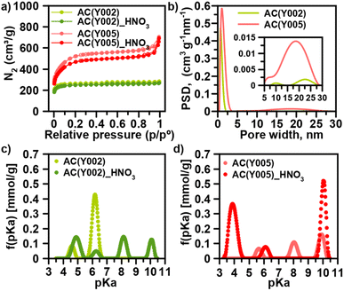
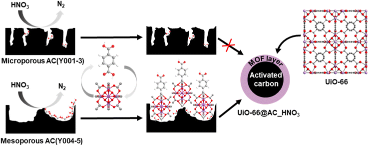
We have selected a set of activated carbon spheres, provided by Blücher company, ranging from microporous AC(Y001–Y003) to micro-/mesoporous AC(Y004 and Y005) (Fig. 1a, b, S1, S2† and Table 1) in order to study the impact of the pore structure on their functionalization and ulterior growth of MOF thin films. In the first step, we selected the micro-/mesoporous activated carbon spheres AC(Y005) to screen optimal surface functionalization conditions with different oxidants (H2O2, HNO3 and (NH4)2S2O8) to provide oxygenated anchoring sites for the MOF thin film layer growth (Scheme 1).13 N2 adsorption was indicative of a diminution of the surface area after oxidation following the trend H2O2 (3.5%) < HNO3 (9.6%) < (NH4)2S2O8 (15.4%) (Fig. 1a, S3 and Table S1†). The X-ray photoelectron spectroscopy (XPS) analysis confirmed an increase in the oxygen concentration on the sphere surface, being more noticeable after the HNO3 and (NH4)2S2O8 treatment (Fig. S4†). In the second step, we carried out an ulterior treatment of the oxidized activated carbon spheres with urea and thiourea, at 450 °C for 30 min under a N2 atmosphere, to explore the impact of the introduction of nitrogen and sulphur groups onto the oxidized carbon surface. XPS analysis demonstrated a clear increase in the surface nitrogen content as well as a decrease in the surface oxygen content (Fig. S5†). Moreover, for the thiourea treated AC spheres, N2 adsorption was indicative of a marked decrease in pore accessibility with a 40% loss of the specific BET surface area (Fig. S3 and Table S1†).| Material | Particle size (μm) | S BET (m2 g−1) | Pore size (nm) | pKaa (mmol g−1) | % DIFP degradation (24 h) |
|---|---|---|---|---|---|
| a Amounts of groups associated with each pKa value. | |||||
| AC(Y001) | 170 | 1460 | 0.9 | 5.03 (0.210), 8.65 (0.050), and 9.80 (0.005) | 18.7 |
| AC(Y001)_HNO3 | 170 | 1100 | 0.7 | 4.55 (0.224), 6.20 (0.012), 7.62 (0.032), and 10.13 (0.130) | 24.1 |
| AC(Y002) | 470 | 790 | 0.7 | 4.60 (0.030) and 6.18 (0.200) | 17.1 |
| AC(Y002)_HNO3 | 470 | 770 | 0.7 | 4.90 (0.089), 6.21 (0.025), 8.14 (0.071), and 10.11 (0.050) | 48.5 |
| AC(Y003) | 470 | 1260 | 0.9 | 5.09 (0.114), 8.06 (0.045), and 9.72 (0.050) | 1.2 |
| AC(Y003)_HNO3 | 470 | 1180 | 0.8, 1.3 | 4.90 (0.089), 6.3 (0.022), 8.14 (0.075), and 10.11 (0.050) | 9.6 |
| AC(Y004) | 390 | 1740 | 1.1, 16 | 6.05 (0.055), 8.40 (0.080), and 9.92 (0.074) | 30.9 |
| AC(Y004)_HNO3 | 390 | 1485 | 0.8, 1.3, 17 | 4.91 (0.089), 6.30 (0.022), 8.18 (0.075), and 10.11 (0.050) | 23.9 |
| AC(Y005) | 475 | 1720 | 1.1, 18 | 5.65 (0.030), 8.05 (0.058), and 9.90 (0.068) | 15.6 |
| AC(Y005)_HNO3 | 475 | 1555 | 1.0, 17 | 3.89 (0.238), 6.16 (0.041), and 10.08 (0.214) | 9.2 |
| UiO-66 LBL | 0.2 | 1155 | 1, 1.9, 2.3, 4–15 | 4.02 (0.157) and 8.57 (3.56) | 25.5 |
| UiO-66-NH2 LBL | 0.3 | 910 | 1, 1.9, 2.3, 4–15 | 4.3 (0.609) and 8.79 (2.27) | 24.1 |
| UiO-66@AC(Y004)_HNO3 | 390 | 1400 | 1.0, 21.1 | 4.84 (0.023), 8.25 (0.0225), and 10.14 (0.900) | 80.7 |
| UiO-66-NH2@AC(Y004)_HNO3 | 390 | 1320 | 1.0, 18.0 | 4.2 (0.072), 8.3 (0.364), and 10.10 (0.390) | 93.9 |
| UiO-66@AC(Y005)_HNO3 | 475 | 1240 | 1.0, 19.0 | 5.74 (0.015), 7.93 (0.050), and 10.10 (0.163) | 89.1 |
| UiO-66-NH2@AC(Y005)_HNO3 | 475 | 1295 | 1.0, 21 | 4.06 (0.095), 6.87 (0.012), and 9.81 (0.070) | 97.5 |
Based on this initial screening, HNO3 oxidation was selected as the optimal treatment for surface functionalization of the microporous AC(Y001–003) and micro-/mesoporous AC(Y004–005) carbon spheres (Table 1). N2 adsorption isotherms indicate that the overall porosity is only slightly modified after the oxidation process (Fig. S6†). Microporous AC(Y002)_HNO3 and AC(Y003)_HNO3 carbon spheres (diameter 470 μm) exhibit a minor surface area loss of 3–6% while the smaller sphere AC(Y001)_HNO3 (diameter 170 μm), with a 25% loss of the surface area, seems to be more sensitive to the oxidative treatment (Tables 1, S2 and Fig. S6†). The mesoporous spheres AC(Y004)_HNO3 (390 μm) and AC(Y005)_HNO3 (475 μm) exhibit a larger surface area loss (10–16%) upon the HNO3 treatment than microporous spheres of a similar size AC(Y002–3)_HNO3 indicating a higher reactivity of the mesopores. The acid–base titration results (Fig. S7–S10†) clearly show an increase in acidity upon the HNO3 treatment, as expected (Tables 1 and S5†). Oxidized mesoporous AC(Y004)_HNO3 and AC(Y005)_HNO3 are more acidic than their microporous counterparts. This is especially seen in the acidic pH region of the acid–base titration curve of AC(Y005)_HNO3, which exhibits a high amount of carboxylic groups (pKa < 4), compared to oxidized microporous AC(Y002)_HNO3 (Fig. 1c and d). These carboxylic groups are very important as seeds for the MOF crystal growth (see below).
Layer by layer growth of MOF on activated carbon spheres
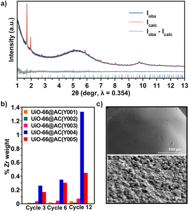
Upon detailed characterization of the functionalised activated carbon spheres, we have studied the impact of their surface functionalities on the growth of thin films of the prototypical UiO-66(-NH2) MOFs by means of the layer-by-layer (LBL) synthesis.13 The LBL MOF growth consisted of the successive immersion of the AC(Y00n)_HNO3 (n = 1–5) spheres in dimethylformamide (DMF)/acetic acid (AcOH) solutions of the oxyhydroxide metal cluster [Zr6O4(OH)4(AcO)12] for 15 minutes at 130 °C followed by washing with DMF and immersion in a DMF solution of the organic linker benzene-1,4-dicarboxylic acid (H2bdc) or bencene-2-amino-1,4-dicarboxylic acid (H2bdc-NH2) for 15 minutes at 130 °C. The general process for UiO-66(-NH2)@AC(Y00n)_HNO3 (n = 1–5) hybrid materials ends after 12 synthetic immersion cycles according to Scheme 1 (experimental details in the ESI†). The LBL growth process was followed by a powder X-ray diffraction (PXRD), Fourier transform infrared spectroscopy (FTIR), inductively coupled plasma-mass spectrometry (ICP-MS), acid–base titration, thermogravimetric analysis (TGA) and N2 adsorption–desorption experiments at 77 K (Fig. 2a, b, S11–S16, Tables 1, S2 and S3†). High resolution-powder X-ray diffraction (HR-PXRD) measurements on UiO-66(-NH2)@AC(Y00n)_HNO3 (n = 4, 5) acquired at European Synchrotron Radiation Facility Beam line ID-22![[thin space (1/6-em)]](https://www.rsc.org/images/entities/char_2009.gif) 31,32 of hybrid materials unequivocally confirm the formation of crystalline pure phase UiO-66(-NH2) thin films (Fig. 2a and S17–S20†). Structureless Le Bail refinement indicates that positions and intensity of the Bragg reflection peaks and cell parameters: a = b = c 20.8288 (3) Å and V = 9036.4 (3) Å3 are in agreement with the formation of crystalline pure phase UiO-66(-NH2) thin films on the surface of the activated carbon spheres. The high background of the pattern is characteristic of the amorphous nature of the activated carbon spheres. ICP-MS analysis clearly shows an appreciable increase in a % Zr weight (and therefore of UiO-66) in AC(Y004–5)_HNO3 throughout different synthetic cycles (Fig. 2b). In fact, a total amount of 3.96 wt% and 1.04 wt% of UiO-66 was introduced to UiO-66@AC(Y004)_HNO3 and UiO-66@AC(Y005)_HNO3 composites, respectively (Table S3†). In addition, we also managed to synthesize UiO-66-NH2@AC composites reaching around 3 wt% of MOF on mesoporous AC(Y004)_HNO3 and AC(Y005)_HNO3 spheres (Fig. S21–27, Tables S3 and S4†). Neither microporous AC(Y00n)_HNO3 (n = 1–3) nor pristine AC(Y004) and AC(Y005) give rise to the formation of a UiO-66(-NH2) thin layer (Fig. S38†). These results indicate that only the oxidized mesoporous spheres AC(Y004–5)_HNO3 give rise to the formation of a MOF crystalline thin layer. We attribute this behaviour to the formation of carboxylic residues at the accessible mesoporous surface (see above) that allows zirconiumoxyhydroxide metal cluster anchoring and resulting a MOF thin layer in UiO-66(NH2)@AC(Y004–5)_HNO3 hybrid materials. Scanning electron microscopy (SEM-EDX) images of the UiO-66(-NH2)@AC(Y004–5)_HNO3 hybrid materials proved the formation of a rather homogeneous MOF layer of octahedral microcrystals covering the AC spheres' surface (Fig. 2c, and S28–S31†). Moreover, the growth of the UiO-66 or UiO-66-NH2 thin film layer does not hamper access to the carbon sphere pore structure, although a slight decrease in the N2 uptake upon MOF growth is noticed (Tables 1, S2, S4, Fig. S12 and S22, †). This result is in agreement with the smaller surface area of UiO-66 (1155 m2 g−1) and UiO-66-NH2 (910 m2 g−1) in comparison to that of the mesoporous carbon spheres, as well as with the possible incorporation of organic linkers (H2bdc or H2bdc-NH2) into the pores of the hybrid material. The latter hypothesis was demonstrated by performing a vigorous DMF wash of the UiO-66@AC(Y005)_HNO3 composite (see the ESI†), with the BET surface area of the hybrid material increasing from 1240 m2 g−1 to 1525 m2 g−1, similar to that of the oxidized carbon spheres (1555 m2 g−1) (Fig. S32†). For comparative reasons, we also synthesized and characterized UiO-66(-NH2) materials using the same conditions as for LBL synthesis terming these materials UiO-66(-NH2) LBL (see ESI, Fig. S33–S37†). The results confirm the formation of 200 nm UiO-66 framework type materials particles. Still, the higher surface area, broader diffraction peaks, larger mesopore contribution and lower organic linker content (TGA traces) of UiO-66(-NH2) LBL in comparison to UiO-66(-NH2) prepared by conventional solvothermal synthesis point to defective structures (see ESI, Fig. S33–37†).33
31,32 of hybrid materials unequivocally confirm the formation of crystalline pure phase UiO-66(-NH2) thin films (Fig. 2a and S17–S20†). Structureless Le Bail refinement indicates that positions and intensity of the Bragg reflection peaks and cell parameters: a = b = c 20.8288 (3) Å and V = 9036.4 (3) Å3 are in agreement with the formation of crystalline pure phase UiO-66(-NH2) thin films on the surface of the activated carbon spheres. The high background of the pattern is characteristic of the amorphous nature of the activated carbon spheres. ICP-MS analysis clearly shows an appreciable increase in a % Zr weight (and therefore of UiO-66) in AC(Y004–5)_HNO3 throughout different synthetic cycles (Fig. 2b). In fact, a total amount of 3.96 wt% and 1.04 wt% of UiO-66 was introduced to UiO-66@AC(Y004)_HNO3 and UiO-66@AC(Y005)_HNO3 composites, respectively (Table S3†). In addition, we also managed to synthesize UiO-66-NH2@AC composites reaching around 3 wt% of MOF on mesoporous AC(Y004)_HNO3 and AC(Y005)_HNO3 spheres (Fig. S21–27, Tables S3 and S4†). Neither microporous AC(Y00n)_HNO3 (n = 1–3) nor pristine AC(Y004) and AC(Y005) give rise to the formation of a UiO-66(-NH2) thin layer (Fig. S38†). These results indicate that only the oxidized mesoporous spheres AC(Y004–5)_HNO3 give rise to the formation of a MOF crystalline thin layer. We attribute this behaviour to the formation of carboxylic residues at the accessible mesoporous surface (see above) that allows zirconiumoxyhydroxide metal cluster anchoring and resulting a MOF thin layer in UiO-66(NH2)@AC(Y004–5)_HNO3 hybrid materials. Scanning electron microscopy (SEM-EDX) images of the UiO-66(-NH2)@AC(Y004–5)_HNO3 hybrid materials proved the formation of a rather homogeneous MOF layer of octahedral microcrystals covering the AC spheres' surface (Fig. 2c, and S28–S31†). Moreover, the growth of the UiO-66 or UiO-66-NH2 thin film layer does not hamper access to the carbon sphere pore structure, although a slight decrease in the N2 uptake upon MOF growth is noticed (Tables 1, S2, S4, Fig. S12 and S22, †). This result is in agreement with the smaller surface area of UiO-66 (1155 m2 g−1) and UiO-66-NH2 (910 m2 g−1) in comparison to that of the mesoporous carbon spheres, as well as with the possible incorporation of organic linkers (H2bdc or H2bdc-NH2) into the pores of the hybrid material. The latter hypothesis was demonstrated by performing a vigorous DMF wash of the UiO-66@AC(Y005)_HNO3 composite (see the ESI†), with the BET surface area of the hybrid material increasing from 1240 m2 g−1 to 1525 m2 g−1, similar to that of the oxidized carbon spheres (1555 m2 g−1) (Fig. S32†). For comparative reasons, we also synthesized and characterized UiO-66(-NH2) materials using the same conditions as for LBL synthesis terming these materials UiO-66(-NH2) LBL (see ESI, Fig. S33–S37†). The results confirm the formation of 200 nm UiO-66 framework type materials particles. Still, the higher surface area, broader diffraction peaks, larger mesopore contribution and lower organic linker content (TGA traces) of UiO-66(-NH2) LBL in comparison to UiO-66(-NH2) prepared by conventional solvothermal synthesis point to defective structures (see ESI, Fig. S33–37†).33
Self-detoxification towards a nerve agent model compound
Once we characterized the different AC spheres and MOF@AC composites, we proceeded to evaluate their functional properties as self-detoxifying adsorbents of nerve agents. With this aim, we have screened the activity of the MOF@AC hybrids and their individual components (AC spheres and Zr-MOFs) towards the adsorption and degradation of a G-type nerve agent model, diisopropylfluorophosphate (DIFP). The activated carbon spheres (AC(Y00n)_HNO3 (n = 1–5)), MOFs (UiO-66(-NH2) LBL) and hybrid MOF@AC materials were spiked with 2 μL of water and 0.3 μL of DIFP (0.865 M, MOF![[thin space (1/6-em)]](https://www.rsc.org/images/entities/char_2009.gif) :
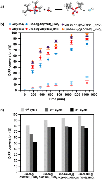
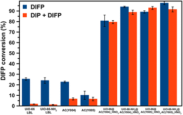
:![[thin space (1/6-em)]](https://www.rsc.org/images/entities/char_2009.gif) DIFP ratio, 1 MOF formula unit: 4 DIFP molecules) and incubated at room temperature in a closed vial. The progress of the detoxification process was assessed by the extraction of unreacted DIFP and its detoxification product, diisopropylphosphate (DIP), with 2 mL of CDCl3 and 0.5 mL of 0.1 M NaDCO3 deuterium oxide solution, respectively. Afterwards, the CDCl3 and D2O extracts were analysed by GC-FID and 1H and 31P NMR (Fig. S39–S45†). The results indicate that only the MOF@AC composites based on HNO3-oxidized mesoporous activated carbon spheres, UiO-66(-NH2)@AC(Y00n)_HNO3 (n = 4, 5), led to a significant DIFP degradation (>90%), yielding non-toxic diisopropylphosphate (DIP) (Fig. 3a, b, S39† and Table 1).
DIFP ratio, 1 MOF formula unit: 4 DIFP molecules) and incubated at room temperature in a closed vial. The progress of the detoxification process was assessed by the extraction of unreacted DIFP and its detoxification product, diisopropylphosphate (DIP), with 2 mL of CDCl3 and 0.5 mL of 0.1 M NaDCO3 deuterium oxide solution, respectively. Afterwards, the CDCl3 and D2O extracts were analysed by GC-FID and 1H and 31P NMR (Fig. S39–S45†). The results indicate that only the MOF@AC composites based on HNO3-oxidized mesoporous activated carbon spheres, UiO-66(-NH2)@AC(Y00n)_HNO3 (n = 4, 5), led to a significant DIFP degradation (>90%), yielding non-toxic diisopropylphosphate (DIP) (Fig. 3a, b, S39† and Table 1).
The observed half-life times for DIFP degradation follow the trend UiO-66-NH2@AC(Y004)_HNO3 (1.8 h) < UiO-66-NH2@AC(Y005)_HNO3 (3.8 h) < UiO-66@AC(Y005)_HNO3 (4.5 h) and UiO-66@AC(Y004)_HNO3 (7.8 h) (Table S6†). Noteworthily, neither UiO-66(-NH2) systems nor the carbon spheres (AC(Y00n)_HNO3, n = 1–5) were able to hydrolyse the P–F bond to that extent (Fig. S40† and Table 1). In the case of the carbon spheres, the poor performance can be related to the typical physisorption of the toxic compound in a hydrophobic pore environment.13 The poor efficiency of UiO-66 and UiO-66-NH2 is linked to the strong interaction of nerve agent degradation products with the oxyhydroxide metal cluster catalytically active sites in unbuffered aqueous media as already reported in the literature.17,34,35 Moreover, we have also tested the performance of a highly dispersed UiO-66(NH2)/AC(Y00n)_HNO3 (n = 4, 5) physical mixture of the same composition of MOF@AC composites (see Section S.3.1 of the ESI†). The results show a 20–30% degradation of DIFP after 24 h (Fig. S49†). The low activity of the MOF/AC physical mixtures points to a lack of synergy between the two components in contrast to MOF@AC composites.
Considering these results, the observed synergistic interplay between UiO-66(-NH2) systems and the carbon spheres can be explained by a strong affinity of the carbon pores for DIP, thereby preventing the poisoning of the catalytically active sites at metal clusters of the MOF framework. This mechanism is plausible given the amphiphilic nature of the DIP molecular structure featuring two hydrocarbon moieties and one phosphate fragment. To confirm this hypothesis, we have measured solid–liquid adsorption isotherms of DIP on the UiO-66(NH2) LBL synthesized materials and AC(Y004)_HNO3, AC(Y005)_HNO3 activated carbon spheres at room temperature. Isotherms fitting to the Langmuir model (Fig. S46†) have allowed the calculation of an α partition coefficient for DIP between the AC and MOF phases according to the following equation: α= (K1 × m2)/(K2 × m1), where K1 and K2 correspond to the Langmuir equilibrium constant of DIP with the activated carbon sphere and MOF material, respectively and m1 and m2 correspond to the respective mass of activated carbon and the MOF in the composite material. The results show the α partition coefficient values in the range 10–30 (Table S7†) which indicate the favourable transfer of DIP from the MOF thin layer to the activated carbon sphere. Afterwards, we studied the inhibitory effect of DIP on DIFP degradation. The results show the total inhibition of the UiO-66(-NH2) catalytic activity for DIFP degradation upon the addition of DIP (Fig. 4). Likewise, the moderate DIFP degradation activity of AC(Y004)_HNO3 and AC(Y005)_HNO3 is also affected by the DIP addition. By contrast, the presence of DIP does not affect the MOF@AC composite catalytic activity (Fig. 4). These observations support the synergistic behaviour of the MOF and AC in the MOF@AC hybrid systems for the degradation of the G-type nerve agent model.
The better performance of the UiO-66-NH2@AC composites than those of UiO-66@AC can be attributed to the nucleophilic nature of the amino residue.34,36 Finally, to extend the application potential of these hybrid materials, we carried out reusability tests (see the ESI† for experimental details). With this aim, we have evaluated the continuous hydrolysis performance of DIFP (0.865 M, 1 MOF formula unit: 4 DIFP molecules) throughout 3 injection cycles (one DIFP injection every 24 h). The results indicate that UiO-66(-NH2)@AC(Y00n)_HNO3 (n = 4, 5) composites are able to detoxify the toxic model compound in the next two cycles, although a slight decrease in percentage degradation (10–30%) (Fig. 3c and Table S8†) is noticed. MOF integrity after each recyclability test was evaluated by PXRD showing that the UiO-66(-NH2)@AC(Y00n)_HNO3 (n = 4, 5) systems were unaffected (Fig. S48†).
Conclusions
We have found that the nature of the pore surface in a series of activated carbon spheres determines its oxidation process as well as the concomitant growth of a MOF thin film layer. The resulting UiO-66(-NH2)@AC composites are able to prevent the secondary emission problem found in classical activated carbon adsorbents. This self-cleaning property positions them as advanced protective filters. The observed synergistic interplay between UiO-66(-NH2) and the carbon spheres can be justified on the basis of a strong affinity of the carbon pores for the nerve agent degradation product DIP, thereby preventing the poisoning of the catalytically active sites at metal clusters of the MOF framework after the P–F bond hydrolysis.Conflicts of interest
There are no conflicts to declare.Acknowledgements
The authors are grateful to Spanish MCIN/AEI/10.13039/501100011033 (Project PID2020-113608RB-I00; TED2021-129886B-C41). CPB is grateful to Spanish MCIN/AEI/10.13039/501100011033 by PRE2021-099867. PD acknowledges the grant PRE2018-084220 funded by Spanish MCIN/AEI/10.13039/501100011033 and FSE. EBM acknowledges Plan Propio de Investigación-Universidad de Granada for a predoctoral fellowship. TJB is grateful to Plan Propio de Investigación-Universidad de Granada for a Visiting Scholar Grant. The authors acknowledge Blücher® for providing them with samples of activated carbon spheres AC(Y00n) (n = 1–5). RV acknowledges programa Juan de la Cierva Formación (FJC2020-045043-I). The authors are grateful to the European Synchrotron Radiation Facility for the beamtime (experiment CH-6718/10.15151/ESRF-ES-1323886503, ID-22 High-Resolution Powder-Diffraction Beamline) and to the local contacts of ID-22 Dr Catherine Dejoie.Notes and references
- E. Fischer, M. M. Blum, W. S. Alwan and J. E. Forman, Pure Appl. Chem., 2017, 89, 249–258 CrossRef CAS.
- S. Mostafalou and M. Abdollahi, Arch. Toxicol., 2017, 91, 549–599 CrossRef CAS PubMed.
- F. Worek, H. Thiermann, L. Szinicz and P. Eyer, Biochem. Pharmacol., 2004, 68, 2237–2248 CrossRef CAS PubMed.
- S. Chauhan, S. Chauhan, R. D'Cruz, S. Faruqi, K. K. Singh, S. Varma, M. Singh and V. Karthik, Environ. Toxicol. Pharmacol., 2008, 26, 113–122 CrossRef CAS PubMed.
- G. Mercey, T. Verdelet, J. Renou, M. Kliachyna, R. Baati, F. Nachon, L. Jean and P. Y. Renard, Acc. Chem. Res., 2012, 45, 756–766 CrossRef CAS PubMed.
- M. Enserink, Science, 2013, 341, 1050–1051 CrossRef CAS PubMed.
- F. Worek, T. Wille, M. Koller and H. Thiermann, Arch. Toxicol., 2016, 90, 2131–2145 CrossRef CAS PubMed.
- H. John, M. J. van der Schans, M. Koller, H. E. T. Spruit, F. Worek, H. Thiermann and D. Noort, Forensic Toxicol., 2018, 36, 61–71 CrossRef CAS PubMed.
- D. A. Giannakoudakis and T. J. Bandosz, Detoxification of Chemical Warfare Agents from WWI to Multifunctional Nanocomposite Approaches, 2018 Search PubMed.
- J. B. Decoste and G. W. Peterson, Chem. Rev., 2014, 114, 5695–5727 CrossRef CAS PubMed.
- D. A. Giannakoudakis, M. Barczak, M. Florent and T. J. Bandosz, Chem. Eng. J., 2019, 362, 758–766 CrossRef CAS.
- M. A. Rahman Bhuiyan, L. Wang, A. Shaid, R. A. Shanks and J. Ding, J. Ind. Text., 2019, 49(I), 97–138 CrossRef.
- R. Gil-San-Millan, P. Delgado, E. Lopez-Maya, J. D. Martin-Romera, E. Barea and J. A. R. Navarro, ACS Appl. Mater. Interfaces, 2021, 13, 50491–50496 CrossRef CAS PubMed.
- R. Osovsky, D. Kaplan, I. Nir, H. Rotter, S. Elisha and I. Columbus, Environ. Sci. Technol., 2014, 48, 10912–10918 CrossRef CAS PubMed.
- D. Kaplan, L. Shmueli, I. Nir, D. Waysbort and I. Columbus, Clean: Soil, Air, Water, 2007, 35, 172–177 CAS.
- I. Columbus, D. Waysbort, L. Shmueli, I. Nir and D. Kaplan, Environ. Sci. Technol., 2006, 40, 3952–3958 CrossRef CAS PubMed.
- E. López-Maya, C. Montoro, L. M. Rodríguez-Albelo, S. D. Aznar Cervantes, A. A. Lozano-Pérez, J. L. Cenís, E. Barea and J. A. R. Navarro, Angew. Chem., 2015, 127, 6894–6898 CrossRef.
- J. E. Mondloch, M. J. Katz, W. C. Isley, P. Ghosh, P. Liao, W. Bury, G. W. Wagner, M. G. Hall, J. B. Decoste, G. W. Peterson, R. Q. Snurr, C. J. Cramer, J. T. Hupp and O. K. Farha, Nat. Mater., 2015, 14, 512–516 CrossRef CAS PubMed.
- T. Islamoglu, Z. Chen, M. C. Wasson, C. T. Buru, K. O. Kirlikovali, U. Afrin, M. R. Mian and O. K. Farha, Chem. Rev., 2020, 120, 8130–8160 CrossRef CAS PubMed.
- P. Li, R. C. Klet, S. Y. Moon, T. C. Wang, P. Deria, A. W. Peters, B. M. Klahr, H. J. Park, S. S. Al-Juaid, J. T. Hupp and O. K. Farha, Chem. Commun., 2015, 51, 10925–10928 RSC.
- H. J. Park, J. K. Jang, S. Y. Kim, J. W. Ha, D. Moon, I. N. Kang, Y. S. Bae, S. Kim and D. H. Hwang, Inorg. Chem., 2017, 56, 12098–12101 CrossRef CAS PubMed.
- M. J. Katz, J. E. Mondloch, R. K. Totten, J. K. Park, S. T. Nguyen, O. K. Farha and J. T. Hupp, Angew. Chem., Int. Ed., 2014, 53, 497–501 CrossRef CAS PubMed.
- M. Pander, R. Gil-San-Millan, P. Delgado, C. Perona-Bermejo, U. Kostrzewa, K. Kaczkowski, D. J. Kubicki, J. A. R. Navarro and W. Bury, Mater. Horiz., 2023, 10, 1301–1308 RSC.
- T. Tian, Z. Zeng, D. Vulpe, M. E. Casco, G. Divitini, P. A. Midgley, J. Silvestre-Albero, J. C. Tan, P. Z. Moghadam and D. Fairen-Jimenez, Nat. Mater., 2018, 17, 174–179 CrossRef CAS PubMed.
- A. X. Lu, M. McEntee, M. A. Browe, M. G. Hall, J. B. Decoste and G. W. Peterson, ACS Appl. Mater. Interfaces, 2017, 9, 13632–13636 CrossRef CAS PubMed.
- D. T. Lee, J. Zhao, G. W. Peterson and G. N. Parsons, Chem. Mater., 2017, 29, 4894–4903 CrossRef CAS.
- K. Ma, Y. H. Cheung, K. O. Kirlikovali, H. Xie, K. B. Idrees, X. Wang, T. Islamoglu, J. H. Xin and O. K. Farha, Adv. Mater., 2023, 2300951 CrossRef PubMed.
- K. O. Kirlikovali, Z. Chen, T. Islamoglu, J. T. Hupp and O. K. Farha, ACS Appl. Mater. Interfaces, 2020, 12, 14702–14720 CrossRef CAS PubMed.
- A. Yao, X. Jiao, D. Chen and C. Li, ACS Appl. Mater. Interfaces, 2019, 11, 7927–7935 CrossRef CAS PubMed.
- M. Kalaj, M. R. Momeni, K. C. Bentz, K. S. Barcus, J. M. Palomba, F. Paesani and S. M. Cohen, Chem. Commun., 2019, 55, 3481–3484 RSC.
- A. Fitch, C. Dejoie, E. Covacci, G. Confalonieri, O. Grendal, L. Claustre, P. Guillou, J. Kieffer, W. de Nolf, S. Petitdemange, M. Ruat and Y. Watier, J. Synchrotron Radiat., 2023, 30, 1003–1012 CrossRef CAS PubMed.
- E. Borrego-Marin, F. J. Carmona and R. Vismara, Unveiling the phosphate adsorption sites in a series of Zr-based MOFs by in situ HR-PXRD [dataset], European Synchrotron Radiation Facility, 2026, DOI:10.15151/ESRF-ES-1323886503.
- G. C. Shearer, S. Chavan, S. Bordiga, S. Svelle, U. Olsbye and K. P. Lillerud, Chem. Mater., 2016, 28, 3749–3761 CrossRef CAS.
- R. Gil-San-Millan, E. López-Maya, M. Hall, N. M. Padial, G. W. Peterson, J. B. DeCoste, L. M. Rodríguez-Albelo, J. E. Oltra, E. Barea and J. A. R. Navarro, ACS Appl. Mater. Interfaces, 2017, 9, 23967–23973 CrossRef CAS PubMed.
- M. C. De Koning, M. Van Grol and T. Breijaert, Inorg. Chem., 2017, 56, 11804–11809 CrossRef CAS PubMed.
- M. J. Katz, S. Y. Moon, J. E. Mondloch, M. H. Beyzavi, C. J. Stephenson, J. T. Hupp and O. K. Farha, Chem. Sci., 2015, 6, 2286–2291 RSC.
Footnotes |
| † Electronic supplementary information (ESI) available. See DOI: https://doi.org/10.1039/d3ta06108f |
| ‡ Equal contribution. |
| This journal is © The Royal Society of Chemistry 2024 |

