
A 3D-printed CuNi alloy catalyst with a triply periodic minimal surface for the reverse water-gas shift reaction†
Wenbin
Li‡
ad,
Junhao
Ding‡
b,
Xiao
Chen
c,
You
Wang
d,
Xu
Song
*b and
Sai
Zhang
 *ad
*ad
aResearch & Development Institute of Northwestern Polytechnical University in Shenzhen, Shenzhen 518057, China. E-mail: zhangsai1112@nwpu.edu.cn
bDepartment of Mechanical and Automation Engineering, Chinese University of Hong Kong, Shatin, Hong Kong 999077, China. E-mail: xsong@mae.cuhk.edu.hk
cSchool of Materials Science and Engineering, North China University of Water Resources and Electric Power, Zhengzhou 450045, China
dSchool of Chemistry and Chemical Engineering, Northwestern Polytechnical University, Xian 710072, China
First published on 18th November 2023
Abstract
The efficient enhancement of mass and heat transfer, as well as mechanical stability, has attracted particular interest for fixed-bed reactors in practical applications. Herein, a monolithic CuNi alloy catalyst with ordered microchannels composed of a triply periodic minimal surface (TPMS) was designed and fabricated using three-dimensional (3D) printing technology, which boosted the highly efficient and robust reverse water-gas shift (RWGS) reaction. The unique TPMS lattice structure enabled the monolithic CuNi catalyst to enhance mass and heat transfer efficiencies, resulting in a significantly improved catalytic performance for the RWGS reaction compared with the monolithic catalyst with a honeycomb structure or the traditional CuNi/Al2O3 catalyst. Furthermore, the 3D-printed monolithic CuNi catalyst exhibited excellent catalytic and mechanical stability at high reaction temperatures. The simple and cost-effective fabrication of conductive metal catalysts with tunable 3D multichannel architectures opens new opportunities in developing heterogeneous catalysts for fixed-bed reactors.
Introduction
Fixed-bed reactors are extensively adopted to manufacture various bulk and/or fine chemicals via gas–solid phase and/or liquid–solid phase reactions, in which the reactants and products pass through the reactor from the void channels of the catalysts.1,2 Generally, the catalyst granules of various sizes and regular shapes (such as spheres, cylinders or rings) are manufactured and used to fill fixed-bed reactors to promote momentum, heat, and mass transfer. However, the disordered accumulation of these catalyst granules easily leads to an irregular bed layer, resulting in unpredictable molecular diffusion or mass transfer in the practical fixed-bed reactor.3–6 Meanwhile, the heat transfer efficiency in the fixed-bed reactor is primarily limited by the multitudinous interface between the catalyst particles and surrounding fluid of the reactant.5,7 Therefore, the unpredictable mass transfer and poor heat transfer of some traditional bed layers frequently form undesirable hotspots in the reactor, which undermine the catalytic performance (activity and/or selectivity) and reduce the catalyst life via carbon deposition or sintering.To solve the aforementioned problem, a monolithic catalyst with ordered microchannels is considered a potential choice.8–12 Benefiting from the submillimetre dimensions, ordered microchannels facilitate both heat and mass transport, enabling reactions to occur faster, more selectively, and with greater energy efficiency in a confined space.7,13–15 Meanwhile, the integrated structural features further ensure heat transfer through the catalyst itself, thereby enhancing the efficiency of heat transfer. In addition, monolithic catalysts generally exhibit significantly enhanced mechanical strength compared to classical catalysts (such as powders, pellets, and extrudates).9,16 Therefore, a monolithic catalyst with a honeycomb structure is the most common one with ordered microchannels.17–20 However, these straight microchannels can still be considerably improved in terms of mass and heat transfer, as well as mechanical strength, via the design of geometric structures using manufacturing technology.
Triply periodic minimal surface (TPMS)-based lattice structures have received considerable attention in various industrial sectors owing to their unique geometric structure of smooth surfaces with zero mean curvature and periodic distribution in three perpendicular directions.14,21–23 Compared with the honeycomb structure, these surfaces can split the space into two interlocked channels through a smooth transition rather than an angular transition.24,25 The smooth and ordered microchannels with a TPMS can decrease the pressure drop and enhance the heat transfer effects and flow efficiency, thereby providing significant potential for the design of monolithic fixed-bed catalysts. In addition, the exceptional mechanical strength derived from the unique geometry of a TPMS can effectively improve the structural stability of a catalyst during actual operation.23,26
Herein, we have fabricated a monolithic CuNi alloy catalyst with ordered microchannels, composed of a typical TPMS, using a three-dimensional (3D) printing technology known as selective laser melting (SLM) to investigate the influence of geometrical structure on the catalytic performance of reverse water-gas shift (RWGS) reactions. The intrinsic catalytic performance of CuNi alloys has been extensively demonstrated to surpass that of their respective pure metals in various reactions.27–30 Also, the RWGS reaction as a model reaction can directly convert CO2 into CO to further synthesise various value-added chemicals.31–34 Combined with computational fluid dynamics (CFD) for gas flow behaviours, we demonstrated that the monolithic catalyst with a TPMS architecture exhibits significantly improved mass and heat transfer compared with the monolithic catalyst with a honeycomb structures. Benefiting from the TPMS-based architectures, the monolithic CuNi alloy catalyst yielded a CO generation rate with a turnover frequency (TOF) of 277 min−1 (based on each exposed active site) at 500 °C, which was 6.4 times higher than that of the CuNi nanoparticle supported on Al2O3 (43 min−1). Additionally, the monolithic CuNi alloy catalyst exhibited remarkable catalytic and mechanical stability even under high temperature conditions of up to 500 °C.
Results and discussion
Geometric modelling of the TPMS-based catalysts
Various TPMSs can be mathematically defined using implicit functions (the detailed procedure is shown in the ESI†).35 Owing to its large surface area and superior mechanical properties, the commonly applied D-type (Diamond Schwarz) TPMS36 was selected to construct monolithic Cu–Ni alloy catalysts with ordered microchannels. Fig. 1a and b show the typical geometric characteristics of the D-type TPMS lattice structure with a large unit cell size (DL3-RD20, where D and L represent the D-type and unit cell length, respectively, and RD is the relative density) and a small unit cell size (DL2-RD20), respectively. Meanwhile, a honeycomb-shaped structure (honeycomb) was also created as a benchmark to highlight the advantages of the TPMS-based architecture in the fixed-bed reactor (Fig. 1c). Different cross-sectional images from XY, ZY and ZX slicing planes for various catalysts could be further obtained in the ESI (Fig. S1†). Notably, the three catalysts were controlled with the same external shape as a cylinder: a diameter of 5.5 mm and length of 15 mm. The detailed geometric properties of the constructed catalysts are listed in Table 1. In particular, the honeycomb catalyst exhibited a surface area comparable to that of DL2-RD20 but with different structural features. Although the same structural features were observed in the DL3-RD20 and DL2-RD20 catalysts, they exhibited different surface areas.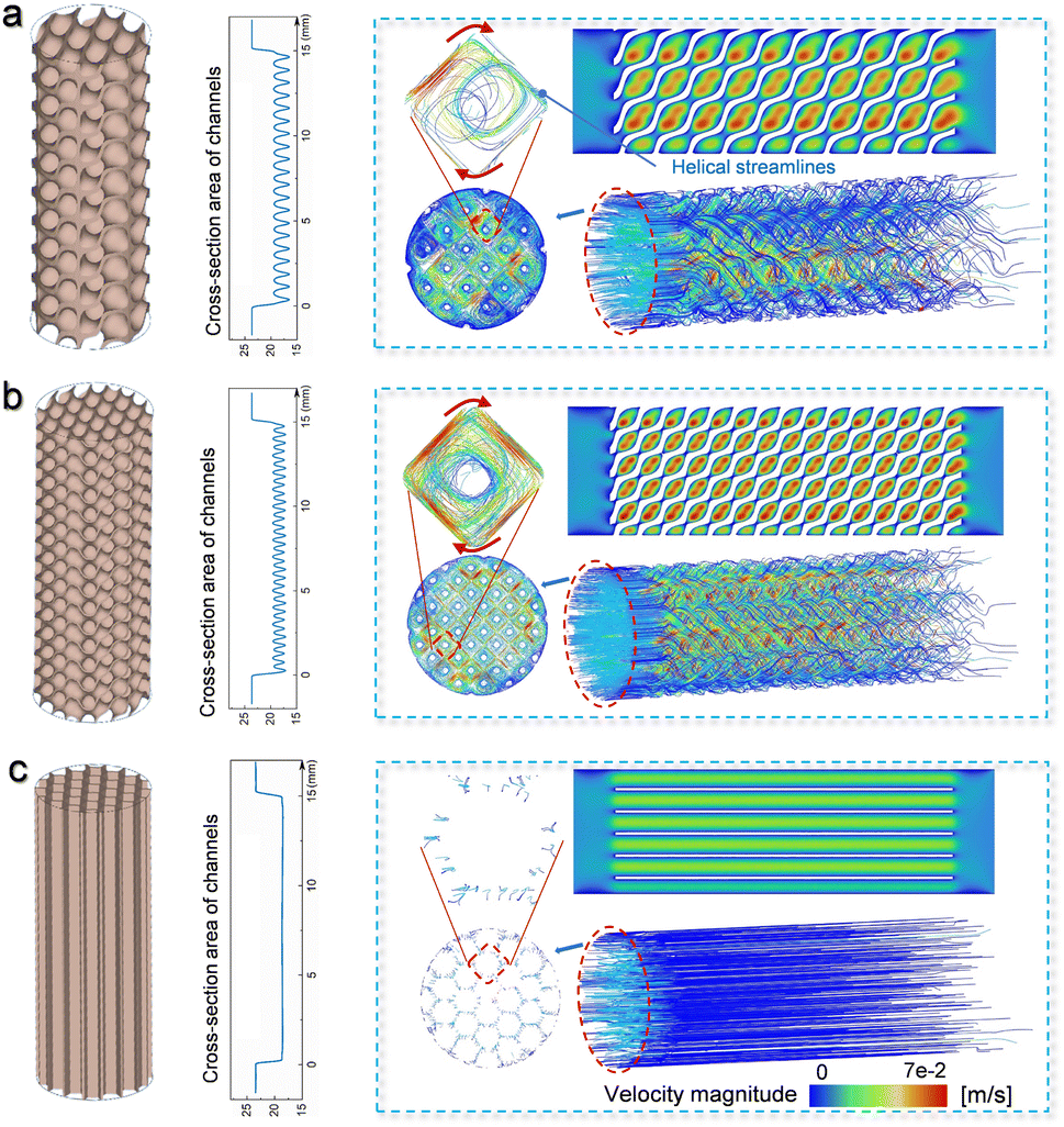 | ||
| Fig. 1 Mass transfer of various monolithic catalysts. Geometric modelling, variation of the cross-sectional area in the longitudinal direction, velocity distribution, and flow pattern for the (a) DL3-RD20, (b) DL2-RD20, and (c) honeycomb catalysts. | ||
| Parameters | Honeycomb | DL3-RD20 | DL2-RD20 |
|---|---|---|---|
| Surface area (mm2) | 1336.1 | 957.1 | 1395.6 |
| Relative density | 20.5% | 20.4% | 20.6% |
| Porosity | 79.5% | 79.6% | 79.3% |
| Solid volume (mm3) | 73.1 | 72.8 | 73.6 |
| Channel diameter (mm) | 1 | 1 | 0.6 |
| Wall thickness (μm) | 110 | 150 | 105 |
| Weight (mg) | 954 | 957 | 704 |
Mass transfer
The influence of the geometric configuration on the mass transfer was investigated by simulating the flow state of the fluid. Because of the constant contour of the honeycomb along its longitude, the cross-sectional area of the fluid channels remained unchanged in the honeycomb catalyst (Fig. 1c). Comparatively, the cross-sectional area of the fluid channels varied significantly in the DL2-RD20 and DL3-RD20 catalysts with the TPMS architecture. In addition, when the flow conditions of the DL3-RD20 and DL2-RD20 catalysts were compared, the TPMS structure with a small unit cell size further enhanced the fluctuation frequency of the cross-sectional area (Fig. 1a and b). Therefore, these differences in the geometric factors directly influence the fluid behaviour of the air passing through the channels.Subsequently, velocity magnitude fields were employed to show the flow patterns in different structures. The inlet velocity was set as 0.014 m s−1, corresponding to the volume speed of 20 mL min−1. As air flowed independently through the separated channels in the honeycomb catalyst, the velocities and flow directions remained almost unchanged (Fig. 1c). The maximum speed of 0.04 m s−1 is achieved for the honeycomb catalyst with a turbulence intensity of 0.037%. In contrast, the velocity-field pattern in the TPMS architecture significantly differed from that in the honeycomb structure (Fig. 1a). Particularly, both the velocity magnitude and trends fluctuated periodically in the TPMS lattice structure, which was directly related to the continuously changing cross-sectional areas. Owing to the interconnected and curved flow channels, the air was repeatedly mixed and redistributed, resulting in periodic acceleration and deceleration. Highly curved streamlines show intense recirculation in the turning regions. Although the turbulence intensity of 0.036 in DL3-RD20 is similar to that in the honeycomb catalyst, the discrete spots with a maximum speed increase to 0.06 m s−1, which is 3.3 times higher than the initial value (0.014 m s−1) at the inlet. Furthermore, the strong helical-motion streamwise flow can be further demonstrated from the view in the longitudinal direction, which squeezes the boundary layer in the channels. Therefore, catalysts with a TPMS structure can cause violent turbulent flow, enhancing mass transport for the catalytic reaction.
When the unit cell size of the TPMS architecture is decreased, the fluctuation frequency is further improved in the DL2-RD20 catalyst (Fig. 1b). Compared with the DL3-RD20 catalyst, the turbulence intensity for DL2-RD20 enhances significantly from 0.036% to 0.15% with a maximum velocity of 0.09 m s−1. The further enhanced flow state results in a higher mass transfer efficiency. Therefore, the DL2-RD20 catalyst, featuring a small unit cell size of the TPMS structure, can transform the random and uncontrollable flow state into a controlled periodic turbulent flow, thereby significantly enhancing mass transfer in a traditional fixed-bed reactor.
Heat transfer
The temperature change in the flowing gas was also investigated via simulations to further evaluate the influence of the geometric structure of the monolithic catalysts on heat transfer. The temperatures of the inlet gas and catalysts were set to 25 and 300 °C, respectively. As the gas flowed through the catalysts, its temperature continuously increased owing to heat transfer from the catalyst (Fig. 2). The temperatures of outlet gas were 60, 90, and 180 °C for the honeycomb, DL3-RD20, and DL2-RD20, respectively. Therefore, the highest outlet temperature directly revealed the most efficient heat transfer for DL2-RD20. Meanwhile, compared with the relatively uniform temperature in the cross sections of DL2-RD20 and DL3-RD20, the non-uniform temperature of the gas in the cross section of the honeycomb catalyst further suggested its low heat transfer efficiency. Therefore, significantly improved mass and heat transfer efficiencies are beneficial for catalytic reactions.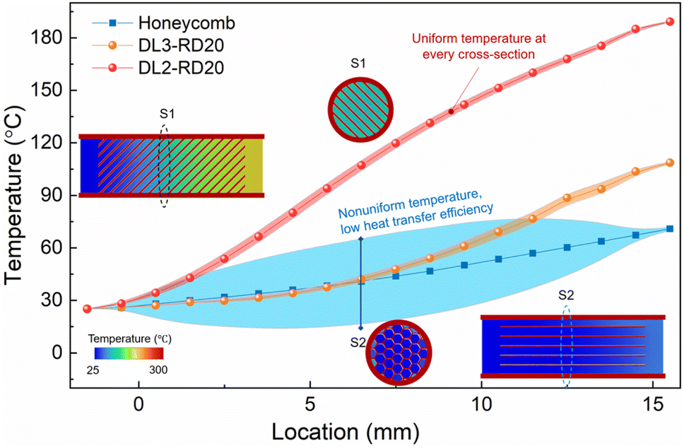 | ||
| Fig. 2 Heat transfer of various monolithic catalysts. Temperature distribution along the longitudinal direction when gases flow through different catalysts. | ||
3D-printing of the designed catalysts
After obtaining the job file, all catalysts were directly printed using a high-precision selective laser melting machine, as shown in Fig. 3a. The metal powders were stored on a dispenser platform and dispensed onto a building platform using a recoater, followed by the selective laser melting process. To enhance the quality of the prepared alloys, pure copper and nickel powders with a molar ratio of 1![[thin space (1/6-em)]](https://www.rsc.org/images/entities/char_2009.gif) :1 were thoroughly pre-mixed using the ball milling process (Fig. S2†). As shown in Fig. 3b, the optical photographic analysis revealed that the as-printed DL2-RD20, DL3-RD20, and honeycomb catalysts exhibited the typical structural features of the theoretical designs (Fig. 1). The average roughness (Ra) of the catalyst surfaces was measured based on depth reconstruction using an RH-200 high-resolution 3D optical microscope. Using the same laser parameters, the surface qualities of the three catalysts were similar. Considering DL2-RD20 as an example, we observed that the low Ra of 2.9 μm was achieved on the upper surface, which could be attributed to the finer laser beam, smaller powder particles, and support of the solidified material (Fig. S3†). For the side or bottom surface, the increased surface Ra of 9.5 μm was mainly derived from the oblique shells and adhesion of powder particles. In particular, the lower surfaces laid on the powder without the support of solidified materials were consistent with the bottom of the molten pool, resulting in the highest Ra of 22.7 μm.
:1 were thoroughly pre-mixed using the ball milling process (Fig. S2†). As shown in Fig. 3b, the optical photographic analysis revealed that the as-printed DL2-RD20, DL3-RD20, and honeycomb catalysts exhibited the typical structural features of the theoretical designs (Fig. 1). The average roughness (Ra) of the catalyst surfaces was measured based on depth reconstruction using an RH-200 high-resolution 3D optical microscope. Using the same laser parameters, the surface qualities of the three catalysts were similar. Considering DL2-RD20 as an example, we observed that the low Ra of 2.9 μm was achieved on the upper surface, which could be attributed to the finer laser beam, smaller powder particles, and support of the solidified material (Fig. S3†). For the side or bottom surface, the increased surface Ra of 9.5 μm was mainly derived from the oblique shells and adhesion of powder particles. In particular, the lower surfaces laid on the powder without the support of solidified materials were consistent with the bottom of the molten pool, resulting in the highest Ra of 22.7 μm.
 | ||
| Fig. 3 Integrated design and fabrication process and macroscopic surface of catalysts via the SLM method. (a) Schematic of the printed process. (b) Side and top surface images of as-printed DL3-RD20, DL2-RD20, and honeycomb catalysts. (c) XRD pattern and (d) SEM images of the DL2-DR20 catalyst at various magnifications. | ||
The microscopic components of the printed catalyst were analysed by X-ray diffraction (XRD). As observed in XRD patterns, the three catalysts exhibited the same single-phase solid solution (Fig. 3c). Also, the peaks at 2θ of 43.7, 50.8, and 74.6° corresponded to the (111), (200), and (220) lattice faces of the FCC crystal structure, respectively. Compared to standard copper (PDF # 04-0836) and nickel (PDF # 04-0850), the shift in the XRD peaks of the as-printed catalyst suggested the formation of CuNi alloys.37,38
Moreover, X-ray photoelectron spectroscopy (XPS) analysis of the as-printed catalyst further indicated the co-existence of Cu and Ni (Fig. S4a†). However, owing to exposure to air, both the surface Cu and Ni elements were partially oxidised, as shown by the analysis of the Cu 3p and Ni 3p peaks (Fig. S3b and c†).
Subsequently, scanning electron microscopy (SEM) was used to observe the microscopic morphologies of the as-printed catalysts. As shown in Fig. 3d, the DL2-RD20 catalyst exhibits typical microchannels, similar to the theoretically constructed geometric channel. The DL3-RD20 and honeycomb catalysts also exhibited the designed geometric channels (Fig. S5†). Energy-dispersive X-ray spectroscopy (EDS) further revealed that the surface mass ratio of Cu:Ni was close to 1:1 (Fig. S6a†), which was maintained on the surface of the catalysts via the line sweep analysis of the EDS data (Fig. S6b†). These results corroborated the formation of a uniform Cu–Ni alloy for the as-printed catalysts.
Catalytic performance
The RWGS reactions were performed at 350 °C with an H2:CO2 ratio of 3:1. As shown in Fig. 4a, with the same surface area, the DL2-RD20 catalyst afforded 13.3% conversion of CO2, which was 1.6 times higher than that of the honeycomb catalyst (8.1%). Meanwhile, with the same geometric structural features, the DL2-RD20 catalyst delivered significantly higher catalytic activity than the DL3-RD20 catalysts (10.3%). Therefore, the highest catalytic activity for the RWGS reaction was achieved by the DL2-RD20 catalyst with TPMS architectures. Furthermore, the three catalysts exhibited satisfactory CO selectivity in the range of 92.4–94.3% (Fig. 4a). Benefiting from the similar selectivity of CO and highest conversion of CO2, the DL2-RD20 catalyst yielded the highest CO generation rate of 2.34 mmol gcat−1 h−1 at 350 °C (Fig. 4b), which was 1.74 and 2.18 times higher than the rates delivered by DL3-RD20 (1.34 mmol gcat−1 h−1) and honeycomb (1.07 mmol gcat−1 h−1) catalysts, respectively. Therefore, the DL2-RD20 catalyst with a small unit cell in the TPMS structure exhibited the best catalytic performance for the RWGS reaction.
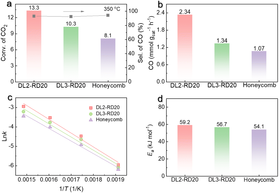 | ||
| Fig. 4 Catalytic performance of the RWGS reaction using various monolithic catalysts. (a) CO2 conversion and CO selectivity afforded by various monolithic catalysts at 350 °C. (b) CO generation rate of various catalysts. (c) lnk, derived from the CO generation rate versus reaction time, as a function of 1/T for various catalysts. (d) Calculated Ea of different catalysts. | ||
Kinetic experiments were performed to confirm the structure-determined catalytic performance in the RWGS reaction. The CO generation rate constant (k) of each catalyst was obtained based on kinetic experiments at 250–400 °C (Fig. S7†, note: the conversions of CO2 were lower than 25%). As shown in Fig. 4c, all catalysts exhibited good linearity between lnk and 1/T, and the corresponding slope of the plot yields the activation energy (Ea). It was seen that the Ea of the RWGS reaction was in the range of 54.1–59.2 kJ mol−1 (Fig. 4d), which implied that the Ea value was not very sensitive to the catalyst structure. The approximately unchanged Ea for various catalysts revealed that the active sites in DL2-RD20, DL3-RD20, and honeycomb are similar owing to their same fabrication process with the same print instrument. After excluding the possible influence of the microstructure, these kinetic results further suggest that the improved catalytic performance of DL2-RD20 was derived from the enhanced efficiency of heat and mass transfer via violent turbulent flow in the TPMS structure.
Subsequently, commercial Al2O3-supported CuNi nanoparticles (CuNi/Al2O3) were also prepared to further investigate the catalytic performance of DL2-RD20. The metal loading on Al2O3 was 3 wt% with a Cu to Ni molar ratio of 1:1. In addition, the clear metal nanoparticles with an average size of 3.2 ± 0.7 nm could be observed from TEM images (Fig. S8†). Under identical reaction conditions, the DL2-RD20 catalyst afforded similar CO2 conversion with 100 mg of traditional CuNi/Al2O3 catalysts (Fig. 5a). To further highlight the advantages of DL2-RD20 for the RWGS reaction, the TOF values based on each of the explored Cu and Ni atoms were calculated. The total surface metal atom of DL2-RD20 was measured as 0.5 μmol g−1 by CO chemisorption. However, the dispersion of the CuNi nanoparticles was 3.0% for the CuNi/Al2O3 catalysts. At 350 °C, the calculated TOF value based on each exposed Cu and Ni atom for the DL2-RD20 catalyst was as high as 77 min−1 (Fig. 5c), which was 12.8 times higher than the value for the CuNi/Al2O3 catalyst (6 min−1). When the reaction temperature was raised to enhance the mass transfer, the conversion of CO2 for CuNi/Al2O3 was higher than that for DL2-RD20 at 500 °C. However, the TOF value of 43 min−1 was still 6.4 times lower than that for DL2-RD20 (277 min−1). In addition, the TOF value of the DL2-RD20 catalyst was also higher than that of previous supported metal catalysts (Table S1†), thereby further revealing its excellent catalytic performance for the RWGS reactions.
 | ||
| Fig. 5 Catalytic performance of DL2-RD20 and CuNi/Al2O3 for the RWGS reaction. (a) CO2 conversion, (b) CO selectivity, and (c) CO generation rate. Reaction conditions: DL2-RD20 or 100 mg CuNi/Al2O3, H2 (15 mL min−1) and CO2 (5 mL min−1). (d) Catalytic stability of DL2-RD20 and CuNi/Al2O3 for the RWGS reaction. Reaction conditions: DL2-RD20 or 100 mg CuNi/Al2O3, H2 (15 mL min−1) and CO2 (5 mL min−1) at 500 °C. | ||
Meanwhile, the DL2-RD20 catalyst exhibited a higher selectivity for CO than that of the CuNi/Al2O3 catalyst, especially in the case of relatively high CO2 conversion at high reaction temperature (Fig. 5a). Considering the RWGS reaction at 500 °C as an example, the CuNi/Al2O3 catalyst yielded 79.7% selectivity for CO, similar to the previously reported CuNi catalysts.39–42 Notably, with a similar CO2 conversion, 93.5% selectivity for CO was obtained by DL2-RD20 at 500 °C. A more efficient mass transfer for the DL2-RD20 catalysts could promote the desorption of CO from the catalyst surface, improving CO selectivity.43,44 Consequently, the CO yield of DL2-RD20 was close to the thermodynamic equilibrium yield of the RWGS reaction at this temperature (Fig. 5b).
Catalytic stability is another important criterion for the evaluation of the current catalysts, especially at relatively high reaction temperatures.45,46 The catalytic stability of DL2-RD20 and CuNi/Al2O3 catalysts was investigated at a relatively high temperature of 500 °C using the H2:CO2 ratio of 3:1 and flow velocity of 20 mL min−1. As shown in Fig. 5d, the conversion of CO2 catalysed by CuNi/Al2O3 decreased from 50.1% to 47.7% after 10 h, suggesting poor catalytic stability. In contrast to CuNi/Al2O3 and the previously reported supported metal catalysts,32,40,47,48 the conversion of CO2 catalysed by DL2-RD20 did not decrease but slowly increased from the initial 40.0% to the final 47.3% after 100 h. The enhanced activity of the DL2-RD20 catalysts can be attributed to the formation of a more uniform CuNi alloy through the reconstruction of the surface atoms at high reaction temperatures. The selectivity of CO was maintained in the range of 93.4–94.6%. After the stability test, the TPMS structural features remained unchanged as is evident from the optical photographs of the spent DL2-RD20 catalysts (Fig. S9†). The DL2-RD20 catalyst exhibits a microscopic morphology and surface structure similar to those of the as-printed catalysts. Therefore, the slightly increased conversion of CO2 and maintained selectivity for CO, as well as the unchanged macroscopic and microscopic structural features revealed the excellent catalytic stability of the DL2-RD20 catalysts for the RWGS reaction at high temperatures.
Mechanical performance
The excellent stability of the DL2-RD20 catalyst further stimulated interest in investigating its mechanical properties. Formulating self-standing configurations with enhanced catalyst compressive strength contributes to an increase in stability and efficiency. The 3D-printed DL2-RD20 catalyst afforded a high yield strength of 46.5 MPa at room temperature (25 °C), whereas the conventional CuNi/Al2O3 catalyst was unable to self-stand (Fig. 6a). Honeycombs, with high mechanical anisotropy, are a common geometry in traditional manufacturing approaches. The compressive stress–strain curves were measured along the vertical and horizontal directions (Fig. 6b). The yield stress along the extrusion direction (vertical) was ∼124 MPa, which was almost three times higher than that in the horizontal direction (42.1 MPa). | ||
| Fig. 6 Mechanical properties of the CuNi monolithic catalyst. (a) Comparison between the conventional fabricated powder catalyst and 3D printed monolithic catalyst. (b) Compression properties in different directions at room temperature. (c) Experimentally captured deformation behavior. (d) Compressive stress–strain curves at evaluated temperatures. (e) Yield stress and plateau stress. (f) Comparison of the mechanical performance of the 3D-printed CuNi alloy and reported structures. The strength and compressive strain for brittle samples were considered at which catastrophic/brittle fracture occurred. For the ductile samples, the yield stress and densification strain were used. | ||
This high strength in the vertical direction was mainly attributed to the full membrane stress states, whereas the stress state became bending-dominated when the compression was performed in the horizontal direction, showing a low strength with a smooth curve. By continuously increasing the loading in the vertical direction of the honeycomb, localised plastic buckling occurred, which was associated with a sudden decrease in stress. Compared with the honeycomb catalysts, the DL2-RD20 catalysts exhibit similar and stable structures in various directions. The smooth curves without any drastic stress dropped further demonstrating the suppression of localised deformation, such as layer-by-layer collapse, shear band, or fracture, during the entire compression process (Fig. 6c). This uniform deformation behaviour indicates the excellent ductility and mechanical stability of the DL2-RD20 catalysts at room temperature.
We investigated the mechanical performance of DL2-RD20 at high temperatures. Under hot compression, the stress–strain curve remained smooth with a minor decrease in strength (Fig. 6d), indicating that the deformation behaviour of the catalyst did not change significantly. When the temperature increased from 25 to 400 °C, the yield strength decreased only by 18.9% (Fig. 6e), suggesting the high thermal stability and mechanical robustness of the catalysts. Subsequently, the specific strength of DL2-RD20 was comparable with that reported previously. As shown in Fig. 6f and Table S2,† all the previously reported architected structures exhibited either brittle failure with relatively low compressive strains or ductile failure with low strength. These results demonstrate the capability of the 3D-printed catalyst with tunable geometries and an exceptional combination of strength and ductility.
Conclusions
In summary, we designed and manufactured monolithic Cu–Ni alloys (DL2-RD20) by selective laser melting for a highly efficient RWGS reaction and excellent catalytic stability. According to the simulation results, the DL2-RD20 catalyst with a D-type TPMS lattice structure can effectively ameliorate mass and heat transfer via an organised periodic turbulent flow in the ordered microchannels. Consequently, the DL2-RD20 catalyst exhibited significantly improved catalytic performance for the RWGS reaction compared to the monolithic catalyst with a honeycomb structure. The DL2-RD20 catalyst yielded a TOF value of 277 min−1 for CO generation, which was 6.4 times higher than that of the traditional CuNi/Al2O3 catalysts. In addition, the DL2-RD20 catalyst also exhibited an excellent mechanical and catalytic stability. The successful development of high-strength monolithic catalysts with specially designed microchannels holds significant potential for the advancement of next-generation catalysts tailored for fixed-bed reactors.Author contributions
Sai Zhang and Xu Song designed the studies. Wenbin Li and Junhao Ding performed most of the experiments. Wenbin Li, Junhao Ding, Xu Song and Sai Zhang performed the data analysis and wrote the paper. All the authors discussed the results and contributed to the manuscript.Conflicts of interest
There are no conflicts to declare.Acknowledgements
The authors acknowledge the Guangdong Basic and Applied Basic Research Foundation (2022B1515020092) and the Shenzhen Science and Technology Program (JCYJ20220530161600002).Notes and references
- A. G. Dixon, Chem. Eng. Sci., 2021, 231, 116305 CrossRef CAS.
- G. R. George, M. Bockelmann, L. Schmalhorst, D. Beton, A. Gerstle, L. Torkuhl, A. Lindermeir and G. D. Wehinger, AIChE J., 2021, 69, e17284 CrossRef.
- N. Jurtz, M. Kraume and G. D. Wehinger, Rev. Chem. Eng., 2019, 35, 139–190 CrossRef.
- A. Chibani, S. Merouani, C. Bougriou and L. Hamadi, Int. J. Heat Mass Trans., 2020, 147, 118939 CrossRef CAS.
- Y. Dong, B. Sosna, O. Korup, F. Rosowski and R. Horn, Chem. Eng. J., 2017, 317, 204–214 CrossRef CAS.
- G. D. Wehinger and S. Flaischlen, Ind. Eng. Chem. Res., 2019, 58, 14410–14423 CrossRef CAS.
- L. Fratalocchi, G. Groppi, C. G. Visconti, L. Lietti and E. Tronconi, Chem. Eng. J., 2020, 386, 123988 CrossRef CAS.
- A. J. Capel, R. P. Rimington, M. P. Lewis and S. D. R. Christie, Nat. Rev. Chem., 2018, 2, 422–436 CrossRef.
- X. Zhou and C.-j. Liu, Adv. Funct. Mater., 2017, 27, 1701134 CrossRef.
- F. Kotz, P. Risch, D. Helmer and B. E. Rapp, Adv. Mater., 2019, 31, e1805982 CrossRef.
- J. Zhu, P. Wu, Y. Chao, J. Yu, W. Zhu, Z. Liu and C. Xu, Chem. Eng. J., 2022, 433, 134341 CrossRef CAS.
- A. S. Díaz-Marta, C. R. Tubío, C. Carbajales, C. Fernández, L. Escalante, E. Sotelo, F. Guitián, V. L. Barrio, A. Gil and A. Coelho, ACS Catal., 2017, 8, 392–404 CrossRef.
- J. Wu, Y. Yan, L. Zhang, Z. Qin and S. Tao, Adv. Mater. Technol., 2018, 4, 1800515 CrossRef.
- L. Han and S. Che, Adv. Mater., 2018, 30, e1705708 CrossRef.
- J. S. Manzano, Z. B. Weinstein, A. D. Sadow and I. I. Slowing, ACS Catal., 2017, 7, 7567–7577 CrossRef CAS.
- O. Al-Ketan and R. K. Abu Al-Rub, Adv. Eng. Mater., 2019, 21, 1900524 CrossRef.
- Q. Wei, H. Li, G. Liu, Y. He, Y. Wang, Y. E. Tan, D. Wang, X. Peng, G. Yang and N. Tsubaki, Nat. Commun., 2020, 11, 4098 CrossRef CAS PubMed.
- P. J. Kitson, S. Glatzel, W. Chen, C.-G. Lin, Y.-F. Song and L. Cronin, Nat. Protoc., 2016, 11, 920–936 CrossRef CAS PubMed.
- C. Zhu, Z. Qi, V. A. Beck, M. Luneau, J. Lattimer, W. Chen, M. A. Worsley, J. Ye, E. B. Duoss, C. M. Spadaccini, C. M. Friend and J. Biener, Sci. Adv., 2018, 4, eaas9459 CrossRef CAS PubMed.
- S. Lawson, X. Li, H. Thakkar, A. A. Rownaghi and F. Rezaei, Chem. Rev., 2021, 121, 6246–6291 CrossRef CAS.
- A. Reddy, M. S. Dimitriyev and G. M. Grason, Nat. Commun., 2022, 13, 2629 CrossRef CAS PubMed.
- C. Park, Y. La, T. H. An, H. Y. Jeong, S. Kang, S. H. Joo, H. Ahn, T. J. Shin and K. T. Kim, Nat. Commun., 2015, 6, 6392 CrossRef CAS.
- T. Yang, Z. Jia, Z. Wu, H. Chen, Z. Deng, L. Chen, Y. Zhu and L. Li, Nat. Commun., 2022, 13, 6083 CrossRef CAS PubMed.
- L. Zhang, S. Feih, S. Daynes, S. Chang, M. Y. Wang, J. Wei and W. F. Lu, Addit. Manuf., 2018, 23, 505–515 CAS.
- D. Clarke, P. Galvosas and D. J. Holland, AIChE J., 2023, e18097, DOI:10.1002/aic.18097.
- Z. Chen, Y. M. Xie, X. Wu, Z. Wang, Q. Li and S. Zhou, Mater. Design, 2019, 183, 108109 CrossRef.
- S. Guan, Y. Liu, H. Zhang, R. Shen, H. Wen, N. Kang, J. Zhou, B. Liu, Y. Fan, J. Jiang and B. Li, Adv. Sci., 2023, 10, e2300726 CrossRef.
- L. Zhou, Y. Liu, S. Liu, H. Zhang, X. Wu, R. Shen, T. Liu, J. Gao, K. Sun, B. Li and J. Jiang, J. Energy Chem., 2023, 83, 363–396 CrossRef CAS.
- X. Wang, J. B. Le, Y. Fei, R. Gao, M. Jing, W. Yuan and C. M. Li, J. Mater. Chem. A, 2022, 10, 7694–7704 RSC.
- M. Zhao, H. Li, W. Yuan and C. M. Li, ACS Appl. Energy Mater., 2020, 3, 3966–3977 CrossRef CAS.
- S. Kattel, P. Liu and J. G. Chen, J. Am. Chem. Soc., 2017, 139, 9739–9754 CrossRef CAS PubMed.
- H. X. Liu, S. Q. Li, W. W. Wang, W. Z. Yu, W. J. Zhang, C. Ma and C. J. Jia, Nat. Commun., 2022, 13, 867 CrossRef CAS.
- A. M. Bahmanpour, M. Signorile and O. Kröcher, Appl. Catal., B, 2021, 295, 120319 CrossRef CAS.
- M. Ziemba, J. Weyel and C. Hess, Appl. Catal., B Environ., 2022, 301, 120825 CrossRef CAS.
- K. A. Brakke, Exp. Math., 1992, 1, 141–165 CrossRef.
- S. T. Hyde and F. C. Meldrum, Science, 2022, 375, 615–616 CrossRef CAS PubMed.
- R. Anderson, J. Terrell, J. Schneider, S. Thompson and P. Gradl, Metall. Mater. Trans. B, 2019, 50, 1921–1930 CrossRef CAS.
- D. García, S. Suárez, K. Aristizábal and F. Mücklich, Adv. Eng. Mater., 2021, 24, 2100755 CrossRef.
- N. Nityashree, C. A. H. Price, L. Pastor-Perez, G. V. Manohara, S. Garcia, M. M. Maroto-Valer and T. R. Reina, Appl. Catal., B, 2020, 261, 118241 CrossRef CAS.
- L.-X. Wang, E. Guan, Z. Wang, L. Wang, Z. Gong, Y. Cui, Z. Yang, C. Wang, J. Zhang, X. Meng, P. Hu, X.-Q. Gong, B. C. Gates and F.-S. Xiao, ACS Catal., 2020, 10, 9261–9270 CrossRef CAS.
- L. X. Wang, L. Wang and F. S. Xiao, Chem. Sci., 2021, 12, 14660–14673 RSC.
- M. Heilmann, C. Prinz, R. Bienert, R. Wendt, B. Kunkel, J. Radnik, A. Hoell, S. Wohlrab, A. Guilherme Buzanich and F. Emmerling, Adv. Eng. Mater., 2022, 24, 2101308 CrossRef CAS.
- Y. Jiang, Y. Sung, C. Choi, G. Joo Bang, S. Hong, X. Tan, T. S. Wu, Y. L. Soo, P. Xiong, M. Meng-Jung Li, L. Hao, Y. Jung and Z. Sun, Angew. Chem., Int. Ed., 2022, 61, e202203836 CrossRef CAS PubMed.
- S. Li, Y. Xu, H. Wang, B. Teng, Q. Liu, Q. Li, L. Xu, X. Liu and J. Lu, Angew. Chem., Int. Ed., 2023, 62, e202218167 CrossRef CAS PubMed.
- S. Hu and W.-X. Li, Science, 2021, 374, 1360–1365 CrossRef CAS.
- M. Rahmati, M. S. Safdari, T. H. Fletcher, M. D. Argyle and C. H. Bartholomew, Chem. Rev., 2020, 120, 4455–4533 CrossRef CAS PubMed.
- X. Zhang, X. Zhu, L. Lin, S. Yao, M. Zhang, X. Liu, X. Wang, Y.-W. Li, C. Shi and D. Ma, ACS Catal., 2016, 7, 912–918 CrossRef.
- A. M. Bahmanpour, F. Héroguel, M. Kılıç, C. J. Baranowski, L. Artiglia, U. Röthlisberger, J. S. Luterbacher and O. Kröcher, ACS Catal., 2019, 9, 6243–6251 CrossRef CAS.
Footnotes |
| † Electronic supplementary information (ESI) available. See DOI: https://doi.org/10.1039/d3ta05845j |
| ‡ These authors contributed equally: Wenbin Li and Junhao Ding. |
| This journal is © The Royal Society of Chemistry 2024 |