 Open Access Article
Creative Commons Attribution 3.0 Unported Licence
Ultra-fast extraction of metals from a printed circuit board using high power ultrasound in a calcium chloride-based deep eutectic solvent†
Rodolfo
Marin Rivera
 *a,
Christopher E.
Elgar
 a,
Ben
Jacobson
b,
Andrew
Feeney
 b,
Paul
Prentice
b,
Karl
Ryder
b,
Paul
Prentice
b,
Karl
Ryder
 a and
Andrew P.
Abbott
 a
a
aSchool of Chemistry, University of Leicester, Leicester, LE1 7RH, UK. E-mail: ramr1@le.ac.uk
bJames Watt School of Engineering, University of Glasgow, G12 8QQ, UK
First published on 18th December 2023
Abstract
The increase of digitization, alongside the growth in consumer electronics and shortened life cycles, has led to a significant global increase in the volume of electronic waste (e-waste). Printed circuit boards (PCBs) are the most valuable components within e-waste due to the higher content of valuable (critical) metals compared to ores. Although some of these metals can be recycled by traditional methodologies, e.g., pyro- and hydrometallurgy, the utilisation of deep eutectic solvents (DESs) offers the opportunity to recover metals from e-waste with higher selectivity and lower toxicity. Yet, DESs are often characterised by very high viscosity, which slows dissolution kinetics. This study investigates the effect of ultrasound on the catalytic dissolution of metals, in the deep eutectic solvent formed from calcium chloride hexahydrated and ethylene glycol. Copper(II) chloride was considered as an oxidising agent, which has high solubility and reversibility in this solvent. High ultrasonic power prevented passivation leading to an enhancement of copper dissolution at a rate 10![[thin space (1/6-em)]](https://www.rsc.org/images/entities/char_2009.gif) 000-times faster than without ultrasound. Thus, leaching rates determined with an optical profiler showed that metals can be extracted from a PCB much faster (7 μm min−1) with high power ultrasound rather than in silent conditions (0.6 μm min−1), and this is discussed in terms of chemical oxidation, passivation and cavitation activity.
000-times faster than without ultrasound. Thus, leaching rates determined with an optical profiler showed that metals can be extracted from a PCB much faster (7 μm min−1) with high power ultrasound rather than in silent conditions (0.6 μm min−1), and this is discussed in terms of chemical oxidation, passivation and cavitation activity.
Sustainability spotlightThe transition towards a low-carbon society will require significant material resources, and will generate substantial amounts of new types of waste. At present, current flows and stocks of electronic residues, such as printed circuit boards can provide major amounts of critical metals and materials, but this is expected to rapidly increase with the development of renewable energy technologies. Although e-waste can be recycled by traditional methodologies, e.g., pyro- and hydrometallurgy, the utilisation of deep eutectic solvents (DESs) offers the opportunity to recover metals from e-waste with higher selectivity and lower toxicity. This work emphasizes the importance of the following UN sustainable development goals: industry, innovation, and infrastructure (SDG 9), responsible consumption and production (SDG 12) and climate action (SDG 13). |
1 Introduction
The significant global increase in the volume of electronic waste (e-waste) is a function of increased digitization with a growth in consumer electronics and shortened life cycles.1 It has been reported that less than 20% of the 55 Mt of annual worldwide e-waste produced is properly collected and processed.2,3 Furthermore, at a production rate of 2.5 Mt per year, it is estimated that by 2030 the volume of electronic waste will increase up to 75 Mt. Europe is the largest producer of e-waste with ca. 17 kg per capita, but is also the continent with the highest documented e-waste collection and recycling (ca. 43%). The UK is one of the highest producers of e-waste per capita (ca. 25 kg per capita). In 2019, it produced a total of 1.6 Mt of e-waste, containing ca. 380![[thin space (1/6-em)]](https://www.rsc.org/images/entities/char_2009.gif) 000 kg of critical raw materials worth £148 M (ca. USD $170 M) a year.4 However, at present, most of the critical raw materials contained within the e-waste generated in the UK are lost, due to the lack of recycling infrastructure, the depletion of waste in pre-processing recycling operations, and losses in high temperature processes.5
000 kg of critical raw materials worth £148 M (ca. USD $170 M) a year.4 However, at present, most of the critical raw materials contained within the e-waste generated in the UK are lost, due to the lack of recycling infrastructure, the depletion of waste in pre-processing recycling operations, and losses in high temperature processes.5
Printed circuit boards (PCBs) contain significant concentrations of different critical/technological metals, such as copper, tin, lead, cadmium, chromium, zinc, nickel and manganese, which can be as high as 30–40 wt%.6 The content of precious metals, such as silver, gold, platinum, and rare-earth elements, on the other hand, can be more than 10 times the concentration found in enriched mineral ores.7 Although some valuable metals, such as iron, copper and gold, are frequently recycled, processing plants do release materials, which represent a serious threat to the environment and human health.8–10 Traditional pyro- and/or hydrometallurgical processing routes are commonly used for recovering metals from e-waste,11–13 but ionometallurgy has been proposed as a more energy-efficient approach for recovering metals,14 and this has recently been applied to e-waste.1,15,16 Ionometallurgy uses non-aqueous solvents of high ionic strength, such as deep eutectic solvents (DESs), which are mixtures of hydrogen bond acceptors (e.g., choline chloride, inorganic salts), with hydrogen bond donor (e.g., ethylene, glycol, urea, glycerol).17 Overall, ionic fluids (e.g., ionic liquids, DESs) tend to have a larger electrochemical potential window than traditional aqueous systems.18 This methodology, uses ambient temperatures, avoids toxic reagents and has reduced water consumption.19 However, the method has relatively slow dissolution kinetics. The use of redox catalyst can help to overcome these issues.20 For instance, through the selection of a particular DES with a redox catalyst, e.g., CuII/I, FeIII/II, iodine/iodide, it is possible to selectively separate the different metals from a substrate such as PCBs or solar photovoltaic cells.21–23 Although the process enables a high selectivity for the separation of metals – contrary to traditional methodologies – the process is mass transfer limited due to the high viscosity of the solvent (ca. 40 mPa s).24 In fact, ionic solvents are often characterised by very high viscosities, which is detrimental for the diffusion of metals ions and conductivity.
New ways to achieve efficient mass transfer between solid and liquid phases have been developed recently for process intensification, such as by using ultrasound reactors. High power ultrasound can lead to both chemical and physical effects, such as fast mass-transport, removal of passivating surface layers and the exposure of new reaction surfaces, as well as radical formation.25–29 Researchers have reported the use of ultrasound-assisted leaching to recover metals from ores in the presence of strong/corrosive mineral acids and bases.30,31 Alternatively, the use of ultrasound on the extraction/recovery of copper in the presence of a DES formed with choline chloride and ethylene glycol has also been reported.32,33 Likewise, the utilisation of high-powered ultrasound was reported to aid in the delamination of active materials from both the cathode and anode of spent lithium-ion batteries.34 Similarly, it was reported that, in the presence of a DES formed with choline chloride and sulfosalicylic acid, ultrasonic erosion increases the total surface area of the material, diminished the thickness of boundary layers, and enhance the dissolution kinetics of metal oxides, such as CoO, Ni2O3, and Mn2O3.35
Here, we report the effect of high-powered ultrasound irradiation on the extraction of metals from a PCB sample in the CaCl2·6H2O:EG eutectic solvent. Initially, the effect of ultrasound on metal oxidation/passivation was investigated in the eutectic solvent, which was compared with etching experiments performed in silent conditions. CuCl2 was used as an oxidising agent due to its electrochemical reversibility and efficiency to solubilise copper. Leaching experiments were performed on pure copper and nickel wires in silent and sonicated conditions, and compared with the etching kinetic of a PCB sample containing copper, nickel and gold. Etching rates were determined by optical profilometry before and after etching. The motion of cavitation bubbles was also investigated in the eutectic solvent, which was compared with the cavitation activity in an aqueous system.
2 Material and methods
The DES was prepared from 1 mol eq. of calcium chloride hexahydrate (CaCl2·6H2O, Fluka, >97%) and 1 mol eq. of ethylene glycol (EG). The solvent was prepared by stirring the components at 60 °C until a colourless homogeneous liquid was formed. The solvent was removed from the heat and stored at room temperature.Ultrasound-assisted etching of pure copper and nickel was performed by considering pure metal wires of 1.25 and 0.25 mm diameter, respectively. The wires were embedded into epoxy resin and polished with SiC abrasive paper down to 1200 grit size, followed by polishing with diamond paste (6, 3, and 1 μm). Anhydrous copper(II) chloride (CuCl2, Acros Organics, 99%) was used as the oxidising agent. Etching was carried out by introducing the block in the DES with a nominal CuCl2 concentration of 1 mol dm−3 when working in silent conditions (but slightly agitated), and 0.1 mol dm−3 when using the ultrasound. A commercial ultrasonic system (Branson Sonics, 1.25DCXa20-V) was used for this study. The system had a cylinder sonotrode of 20 mm diameter, operating at 20 kHz, with a power variable up to 1250 W (maximum power intensity of 398 W cm−2). The ultrasonic horn was placed at a distance of 1 cm above the resin block. The sample was etched step-wise in 40 mL of eutectic solvent. Experiments in silent conditions lasted 60 min and were performed at 50 °C. In the experiments with ultrasound, four sonication pulses of 30 s were applied per experiment, and the temperature of the solution was kept below 60 °C by using a thermostatic bath (Julabo DYNEO DD-300 F). After each ultrasonic pulse, the sample was removed from the solvent, rinsed with acetone and dried in air to be analysed in an electronic optical microscope. 2D and 3D optical images of the sample were captured by using a Zeta Instruments Zeta 2000 optical profiler using the inbuilt Zeta3D software version 1.8.5. Images were constructed by determining the features of an image that are in focus at different heights. These were then analysed to produce a reconstructed 3D topography of the surface of the resin block sample containing the metal wires. Line profiles were measured across the surface, where the dissolution rate was measured using a flat surface of an insoluble phase, that in this case corresponded to the substrate holding the wires, to provide a reference height. After the corresponding images were obtained, the sample was returned to the solvent to be sonicated.
The electrochemical measurements were conducted using a three-electrode system, a platinum flag counter electrode, Ag/AgCl saturated in 3 M KCl solution as a reference electrode, and copper and nickel disc (of 1.25 and 0.25 mm diameter, respectively) as working electrodes. The experimental setup used for electrochemical measurement is described in Fig. S3 in the ESI.† Linear sweep voltammetry (LSV) experiments were performed in silent and sonicated conditions (using the same ultrasonic device), using an IVIUMnSTAT potentiostat/galvanostat with the corresponding software. The LSV scan rates were recorded between 10 and 100 mV s−1. Before each experiment, the working electrode was polished with 0.3 and 0.05 μm alumina slurry, rinsed with acetone, and air dried.
The cavitation activity and mass transport/streaming effects induced within the DES by the power ultrasound was assessed via high-speed imaging (Fastcam SA-Z 2100 K, Photron, Bucks UK) of the tip of a 500 W, 20 kHz ultrasonic horn (Sonics, Newton, Connecticut, USA), during 15 s sonication at 30% input power. A Perspex disk positioned ca. 4 mm below the tip of the horn, provided a surface to mimic the influence of a PCB sample on the cavitation development during the etch-rate measurements. To capture cavitation structure and flow effects throughout the duration of each sonication, imaging was undertaken at 5 × 10³ frames per second (kfps), via a macro-lens (Milvus 100 mm f/2 M, Zeiss, Oberkochen, Germany) and a 36 mm extension tube, achieving a spatial resolution of 35 μm per pixel. Illumination was provided via synchronous (to frame capture) 10 ns laser pulses at 640 nm (CAVILUX Smart, Cavitar, Tampere, Finland), coupled to a liquid light guide and a collimating lens. This configuration facilitates shadowgraphic imaging, whereby refractive index variations introduced through density or pressure fluctuations (above threshold values) during the sonication, are also apparent. Whilst the spatial and temporal resolution of the imaging are insufficient to fully resolve the cavitation dynamics of any individual bubble, they do allow the multi-phase flow and bubble structure evolution within the DES around the tip to be assessed, throughout the 15 s sonication. Moreover, bubble collapse shock waves (impulsive pressure transients generated on bubble implosion) – reported as influential for material exfoliation and delamination36 – may also be imaged directly. For comparative purposes, equivalent observations were also undertaken with the tip of the ultrasonic horn immersed in demineralised water as a host medium for which the cavitation generated by power ultrasound were better understood and characterised.
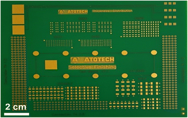
The ultrasound-assisted extraction of metals from a printed circuit board (PCB) was studied by considering a gold-coated PCB with block terminals of different geometries (kindly provided by Atotech UK Ltd, Fig. 1). The sample did not have any additional components, e.g., RAM, chips, and/or integrated circuits soldered to the substrate. The rectangular block terminals were separated from the PCB and used as individual samples for experimentation. These experiments were carried out by introducing the PCB in the DES with a nominal CuCl2 concentration of 1 mol dm−3, and sonicated with 50% power intensity during three cycles of 30 s each (accumulative time of 90 s). 2D and 3D optical images of the sample were captured by the same optical profiler.
3 Results and discussion
3.1 Metal dissolution from a PCB in silent condition – brief review
It was previously reported the catalytic dissolution of metals from PCBs in the CaCl2·6H2O:EG eutectic solvent as a potential autocatalytic methodology for selective metal recovery from PCBs. This particular solvent has higher conductivity, lower viscosity and lower glass transition temperature compared to traditional DESs based on quaternary ammonium salts. Although, the CaCl2·6H2O![[thin space (1/6-em)]](https://www.rsc.org/images/entities/char_2009.gif) :
:![[thin space (1/6-em)]](https://www.rsc.org/images/entities/char_2009.gif) EG eutectic systems with ratios 1
EG eutectic systems with ratios 1![[thin space (1/6-em)]](https://www.rsc.org/images/entities/char_2009.gif) :
:![[thin space (1/6-em)]](https://www.rsc.org/images/entities/char_2009.gif) 2 and 2
2 and 2![[thin space (1/6-em)]](https://www.rsc.org/images/entities/char_2009.gif) :
:![[thin space (1/6-em)]](https://www.rsc.org/images/entities/char_2009.gif) 1 have already been reported in the literature, the 1
1 have already been reported in the literature, the 1![[thin space (1/6-em)]](https://www.rsc.org/images/entities/char_2009.gif) :
:![[thin space (1/6-em)]](https://www.rsc.org/images/entities/char_2009.gif) 1 ratio system is the optimal system in terms of viscosity (ca. 40 mPa s) and conductivity (ca. 19 mS cm−1), which is comparable to that observed in ChCl
1 ratio system is the optimal system in terms of viscosity (ca. 40 mPa s) and conductivity (ca. 19 mS cm−1), which is comparable to that observed in ChCl![[thin space (1/6-em)]](https://www.rsc.org/images/entities/char_2009.gif) :
:![[thin space (1/6-em)]](https://www.rsc.org/images/entities/char_2009.gif) 2EG (viscosity of 37 mPa s and conductivity of 7.6 mS cm−1). Further properties of calcium chloride-based systems have been reported by Hartley et al. (2022).24 In addition, CaCl2 is the major dissolved component in distillation wastewater generated in the Solvay process for the production of sodium carbonate.37 On the other hand, EG is already produced in large quantities as it is commonly used in a wide range of applications, such as coolant and heat transfer agent, and/or anti-freezing agent.
2EG (viscosity of 37 mPa s and conductivity of 7.6 mS cm−1). Further properties of calcium chloride-based systems have been reported by Hartley et al. (2022).24 In addition, CaCl2 is the major dissolved component in distillation wastewater generated in the Solvay process for the production of sodium carbonate.37 On the other hand, EG is already produced in large quantities as it is commonly used in a wide range of applications, such as coolant and heat transfer agent, and/or anti-freezing agent.
Two oxidising agents were reported as redox catalysts in this medium, FeCl3 and CuCl2, as both of them demonstrate high solubility and fast electron transfer. In terms of metal solubilisation, it was demonstrated that due to gold's positive redox potential (about 0.4 V) did not dissolve, whereas nickel also resulted less reactive presumably due to the formation of a passivating film, as consequence of the relatively high-water content in this particular DES (21.3 mol kg−1). Thus, the catalysts selectively solubilise copper, allowing gold and nickel to be recovered by simple filtration. Leaching rates determined with an optical profiler showed that CuCl2 enabled faster leaching kinetics (0.6 μm min−1) and was thus a more effective oxidising agent compared to FeCl3 (0.1 μm min−1). Still, the average metal extraction rate was about 0.35 μm min−1, which was limited by the relatively high viscosity of the solvent (40.1 mPa s). Further details on the catalytic dissolution of copper, nickel and gold from a PCB sample in this particular DES have been published elsewhere.22
3.2 Effect of ultrasound on metal oxidation/passivation
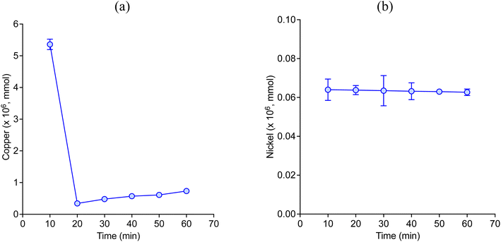
Fig. 2 describes the etch depth of pure copper and nickel wires during 1 hour of experiment (silent condition) in CaCl2·6H2O:EG with 1 mol dm−3 of CuCl2 as oxidising agent. The maximum etch depth registered by both two metals was observed in the first 10 min of etching, which significantly decreased afterward. During the solubilisation of metallic copper, the majority pass into the solution as CuI species according to eqn (1), i.e. [CuCl2]− and [CuCl3]2−,22,24 which tend to accumulate at the interface between the metal and the liquid. Over time, some of the CuI ions may be re-oxidised into CuII ions by reacting with oxygen present either in the surrounding air and/or the oxygen present in the solvent, as described by eqn (2).| CuII + Cu0 → 2CuI | (1) |
 | (2) |
However, as the oxidising agent was deliberately added in excess, CuII species such as [CuCl4]2− and [CuCl3]− were also expected to be present. CuI species tend to have lower solubility than CuII species in the presence of water molecules,38,39 and for the same reason CuI species tend to precipitate as crystalline CuCl particles on the surface, hindering the dissolution of metallic copper. The slightly increase in the etch depth of copper after 20 min could be caused by the mechanical removal of CuCl particles as the solution was slightly agitated. On the other hand, it is known that nickel tends to form complexes either with the anion or with an oxygen donor (usually in the form of H2O) of the DESs depending on its concentration and temperature, which affect its solubilisation. For instance, nickel can form complexes with EG, i.e. [Ni(EG)3]2+,24 whereas trichloro complexes with two or three hydrated water molecules can also be formed in the presence of water (water content above 5 wt%).39
Fig. 3 shows the LSV for the anodic process of copper and nickel disk electrodes in CaCl2·6H2O:EG in silent condition at different scanning rates. These results confirm that both two metals can be electrochemically oxidised in this medium. However, the sudden decrease in current following the corresponding peaks is characteristic of a passivation process,38,40 which appears at more positive potentials when increasing the scanning rate. Part of the passive layer tends to remain attached to the electrode surface, as it was observed by the current slightly increase after reaching the maximum peak, particularly in copper (Fig. 3a). These results confirm that both two metals tend to passivate by which their solubilisation rate can be significantly reduced, as it was observed in Fig. 2.
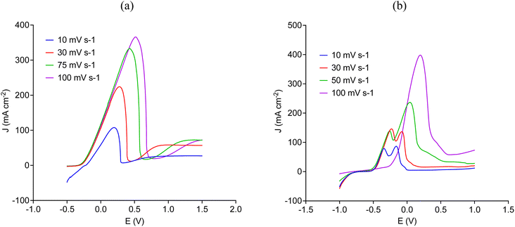 | ||
| Fig. 3 Anodic linear sweep voltammetry (from top left) of (a) copper and (b) nickel in CaCl2·6H2O:EG in silent condition at different scanning rates. | ||
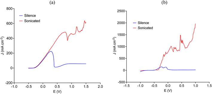
Fig. 4 shows that ultrasound significantly increases the current density by overcoming the passivation process, which was independent of the scanning rate. Notice that Fig. 4 describes the anodic LSV of copper and nickel at a scanning rate of 30 mV s−1, other scanning rates can be seen in Fig. S1 and S2 in the ESI.† In the case of copper (Fig. 4a), the initial rising part of the linear sweep is most likely due to the formation of [CuCl2]− or [CuCl3]2− species, whereas nickel (Fig. 4b) could have been coordinated either with EG molecules by forming [Ni(EG)3]2+ species or with chloride to form tetrahedral [NiCl4]2− species.22,24 As the layer of the ionic medium at the electrode surface becomes enriched in less soluble ionic species, the high activity of cavitation bubbles around the electrode (see Fig. 6) allows preventing the layer of crystalline material to precipitate onto the electrode surface, resulting in a significant increase in current density.
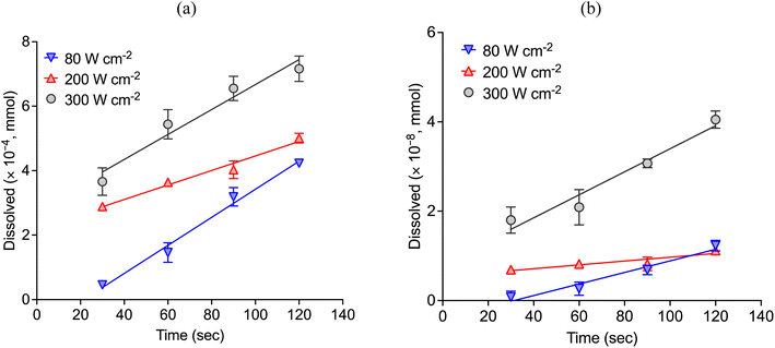
Fig. 5 shows the etch depth of copper and nickel wires over time under the effect of different ultrasonic power in CaCl2·6H2O:EG with CuCl2 as oxidising agent. As it is shown, the amount of copper and nickel that passes into the solution increases when increasing the power intensity. Table 1 describes the etching rates of copper and nickel in silent and sonicated conditions. Ultrasound enables a significant improvement in the dissolution rate of copper (Fig. 5a), as with a relatively low concentration of CuCl2, the dissolution rate was more than 10![[thin space (1/6-em)]](https://www.rsc.org/images/entities/char_2009.gif) 000-times faster with ultrasound compare to the etching rate in silent condition (Fig. 2). It must be noticed that contrary to the experiments performed in silent conditions with 1 mol dm−3 of CuCl2, experiments under the effect of ultrasound were performed with 10-time less oxidising agent, i.e. only 0.1 mol dm−3 of CuCl2. The etching rate of nickel (Fig. 5b), on the other hand, was slightly enhanced with the use of ultrasound. Although, nickel speciation under the effect of ultrasound has not been reported in the literature, it is known that cationic complexes are formed at room temperature, whereas chloride anionic species tend to prevail when the temperature is high (e.g., above 50 °C).39 In addition, nickel has more susceptibility to water molecules than copper, as oxygen becomes incorporated into the first coordination shell. As it was observed, under the effect of ultrasound a small amount of nickel was also solubilised.
000-times faster with ultrasound compare to the etching rate in silent condition (Fig. 2). It must be noticed that contrary to the experiments performed in silent conditions with 1 mol dm−3 of CuCl2, experiments under the effect of ultrasound were performed with 10-time less oxidising agent, i.e. only 0.1 mol dm−3 of CuCl2. The etching rate of nickel (Fig. 5b), on the other hand, was slightly enhanced with the use of ultrasound. Although, nickel speciation under the effect of ultrasound has not been reported in the literature, it is known that cationic complexes are formed at room temperature, whereas chloride anionic species tend to prevail when the temperature is high (e.g., above 50 °C).39 In addition, nickel has more susceptibility to water molecules than copper, as oxygen becomes incorporated into the first coordination shell. As it was observed, under the effect of ultrasound a small amount of nickel was also solubilised.
| Condition | Copper | Nickel |
|---|---|---|
| a Considering the period of time between 20 and 60 min (Fig. 2a). b Considering the average etch depth (1.1 × 10⁻⁹ mmol min−1, Fig. 2b). | ||
| Silent | 7.4 × 10⁻⁷a | 2.2 × 10⁻⁶b |
| Ultrasound with 80 W cm−2 | 2.1 × 10⁻² | 1.6 × 10⁻⁵ |
| Ultrasound with 200 W cm−2 | 1.1 × 10⁻² | 5.4 × 10⁻⁷ |
| Ultrasound with 300 W cm−2 | 1.9 × 10⁻² | 3.2 × 10⁻⁷ |
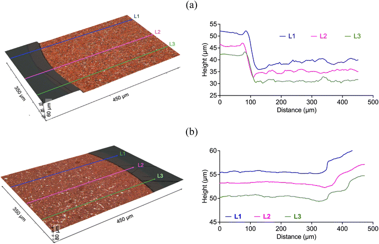
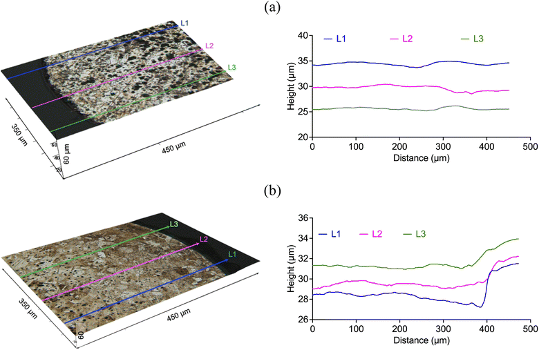
Fig. 6 and 7 describe the etching depth of copper and nickel, respectively, in silent (60 min) and sonicated conditions (120 s, 300 W cm−1). In the case of copper, the 3D images confirmed that it was etched in both two cases. Although the average depth obtained in silent condition (14 ± 0.9 μm) was higher than with ultrasound (4.4 ± 0.6 μm), the dissolution rate of copper was significantly enhanced by the effect of cavitation bubbles, which was approximately 10 folds faster (2.2 μm min−1) than in silent condition (0.23 μm min−1). Nickel, on the other hand, did not show signs of etching in silent condition (Fig. 7a), but about 2.9 ± 0.3 μm were extracted under the effect of a relatively high ultrasonic power intensity at a rate of 1.5 μm min−1 (Fig. 7b). Interestingly, nickel showed a different texture morphology under the effect of cavitation bubbles relative to the experiment performed without ultrasound. Whilst in silent condition, less soluble nickel product could have precipitated on the metallic surface – hindering its dissolution and passivating it – the motion of cavitation bubbles at the interface (Fig. 9) could have prevent the formation of such passivating layers, allowing the metal to dissolve.
3.3 Cavitation activity
High-speed imaging was used to assess the cavitation-bubble activity and mass transfer effects, induced during sonication. We present observations in both deionised water (Fig. 8) and the CaCl2·6H2O:EG eutectic system (Fig. 9), for identical sonication parameters. Ultrasonic horn sonications in water are well studied,41–43 in comparison to sonications in more viscous liquids generally, and ionic liquids/deep eutectic solvents, in particular.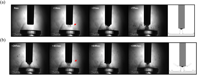 | ||
| Fig. 8 Cavitation activity in demineralised water. Representative frames from a high-speed shadowgraphic sequence captured at 5 kfps during a 15 s sonication at 30% power in water over (a) first ∼50 ms and (b) up to ∼1 s, which also represents the activity throughout the remainder of the sonication. Red arrows indicate bubble-collapse shockwaves. The schematic represents the flow that can be observed from the imaging data in movie format available as ESI.† Scale is provided by the 6.4 mm diameter tip of the ultrasonic horn. | ||
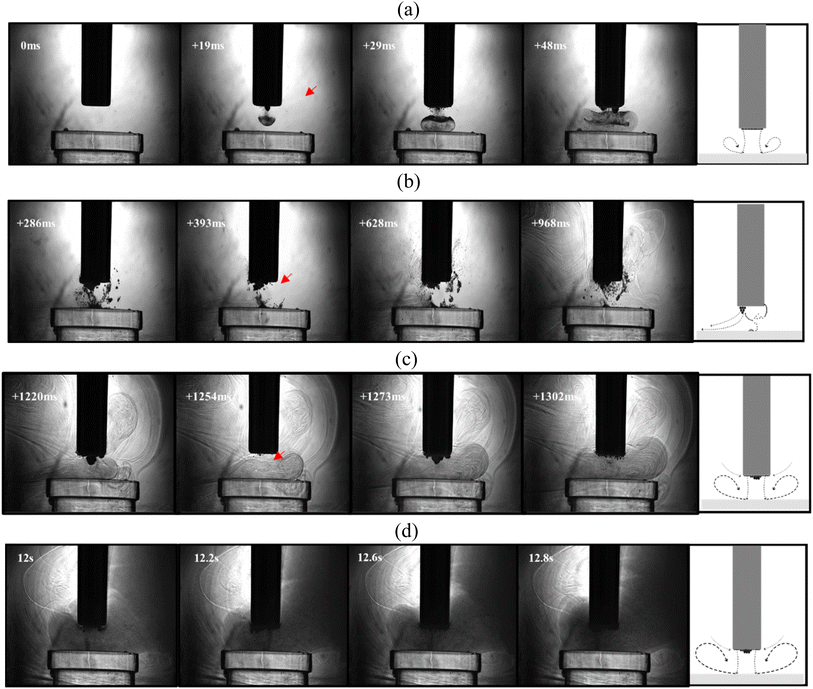 | ||
| Fig. 9 Cavitation activity in CaCl2·6H2O:EG. Representative frames from a high-speed shadowgraphic sequence captured at 5 kfps, during a 15 s sonication at 30% power, in proximity to the surface of a Perspex disk. (a) Initial ∼ 50 ms, (b) up to 1 s, (c) ∼1–1.3 s, and (d) 12–13 s. Red arrows indicate bubble-collapse shockwaves. A schematic representing the flow observed during each regime is presented alongside the selected frames from the sequence (apparent from imaging data in movie format available as ESI†). Scale is provided by the 6.4 mm diameter tip of the ultrasonic horn. | ||
In water, the primary cavitation zone beneath the tip is often characterised by development of a cone-like bubble structure,43,44 such as that captured at 205 ms (Fig. 8b). Fig. 8a depicts the development of the conical bubble structure from the start of the sonication, with other frames in Fig. 8b capturing oscillations of the cavitation structure, including bubble collapse shock waves (arrowed red, throughout). The sonication also induces a downward flow in the region below the tip (also known as acoustic streaming), which circulates through the bulk liquid in counter-propagating swirls to each side of the probe.45,46 Bubbles forming during the sonication, or particles added to the liquid, can be used to trace this flow, as per the schematic representations included within Fig. 8 and better appreciated from the data in movie format (available as ESI†).
For a sonication in DES, the high viscosity may be expected to influence the better-known effects in water. Fig. 9 demonstrates that a downward stream of bubbles develops into an ‘inverted mushroom’ morphology, which is attributable to the higher viscosity (ca. 40 mPa s in this particular DES). Once the stream impacts the Perspex surface, a densely packed bubbly vortex forms, spreading to approximately twice the width of the tip-diameter, and is sustained for several milliseconds. For the rest of the first second of the sonication (Fig. 9b), the vortex evolves into a bulbous bubble structure extruding from the edge of the tip, notably different to the conical structure formed at an equivalent stage of the sonication in water, and reminiscent of the structure reported as forming during sonication of glycerine.47 From around 1.2 s into the sonication of DES (Fig. 9c), the cavitation activity bears a closer resemblance to that generated in water; with the appearance of a primary cluster in contact with the horn tip, oscillating to generate bubble collapse shockwaves,48 as highlighted by the red arrows. Then, the most notable difference between the two liquids is the fine bubble-mist sustained by the higher viscosity of the DES, which extends through much of the field-of-view by the end of the sonication period (Fig. 9d), which allows the acoustic streaming flow to be qualitatively assessed, as represented schematically within Fig. 9 (data in movie format is available as ESI†).
These observations suggest that the comparatively well studied counter-swirling flow profiles induced by an ultrasonic horn sonication in water, are also induced within DES, but are confined to within smaller volumes at higher viscosities. We also expect that friction effects within initially viscous liquids may cause significant temperature variations, which will then alter the viscosity, which could at least in part account for the more complex cavitating environment seen during the sonication of the DES. Nonetheless, improved mass transfer under sonication is evident in each liquid.
3.4 Ultrasound-assisted metal extraction from a gold-coated printed circuit board
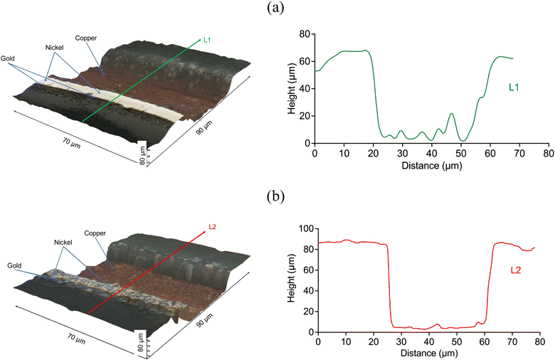
The PCB sample hereby investigated corresponded to the same sample investigated by Rivera et al. (2022),22 and it was composed of three metal layers. A first layer of copper was located in direct contact with the substrate, and was thick enough (∼47 μm) to enable the transmission of electrical signals. A thin layer of nickel (∼7 μm) and a fine layer of gold (∼1.0 μm) were located on top of the copper layer, as described in Fig. 10. All the block terminals within the PCB sample shown in Fig. 1 had the same metal distribution.As it was described in section 3.1, the utilisation of CuCl2 as oxidising agent in CaCl2·6H2O:EG enables a high selectivity for the separation of metals from a PCB, but the methodology is limited by the relatively high viscosity of the medium and the limited solubility of less reactive metals, such as gold and nickel. However, it is believed that metals can be effectively extracted from the substrate by enhancing the dissolution of copper located underneath. This was confirmed by analysing the 3D reflected light images of the cross section of a block terminal after etching in silent (Fig. 11a) and under the effect of ultrasound (Fig. 11b). As it is observed, copper resulted preferentially etched over nickel and gold, particularly under the effect of ultrasound. Considering the cross section of a PCB block terminal, the dissolution rate of copper was about 3 μm min−1, whereas in silent condition the process was just 0.3 μm min−1.
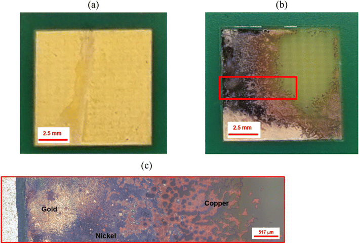
Fig. 12 shows the effect of ultrasound on the extraction of the metal deposit from a PCB block terminal. The sample was under sonication for an accumulative time of 90 s (three cycles of 30 s). Part of the metallic deposit was partially separated from the substrate during the etching process (the distance between the sonotrode and the sample was 4 mm). Metals were removed from the substrate at a calculated rate of ca. 7 μm min−1, which resulted approximately 20-times faster than the dissolution rate observed in silent condition. While no other studies have shown enhanced etching rates using ultrasound in DES, investigations into the electrodeposition of metals have shown that ultrasound can increase deposition rates by approximately 10 times.33,49,50 Thus, ultrasound enabled a significant enhancement in the transport of ionic species due to the combined effect of chemical oxidation and cavitation activity (Fig. 4) in the vicinity of the surface. During ultrasonic irradiation, the gold-coating layer becomes wrinkled (Fig. 12c), while cracks and pores defects were formed on the surface due to the action of pressure waves at the interface (Fig. 8). The formation of defects was enhanced mostly by the dissolution of the underneath copper layer in the presence of CuCl2.
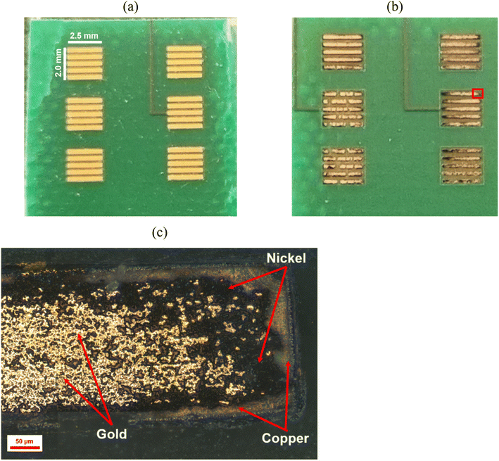 | ||
| Fig. 12 (a) Initial sample of a gold-coated printed circuit board (section located at the top right in Fig. 1). (b) The same sample after 90 s of ultrasonic (200 W cm−2) etching with 1 mol dm−3 CuCl2 in ChCl:2EG. (c) Reflected light image of the delimited area (red square) described in (b). | ||
Fig. 13 shows the effect of ultrasound on the etching of a single square-shape block terminal. A significant portion of the metallic deposit was removed from the upper-right side of the sample when the ultrasonic irradiation was focused in an area of ca. 0.375 cm2 (Fig. 13b). Part of the underlying copper layer remained visible when nickel and gold layers were removed. The metallic deposit was separated from the substrate in less than 8 min at a rate of ca. 0.35 g cm−2 min−1. Although a small fraction of nickel could also be solubilised, further investigation is still ongoing due to its complex nature.
4 Conclusions
In this study, it is shown that despite the high viscosity of DES, a fast separation of metals from a PCB sample can be achieved using high power ultrasound. It was demonstrated that copper and nickel tend to passivate in silent condition by which their kinetics are slow. Ultrasound optical profilometry was used to measure the dissolution rate of pure copper and nickel. Copper dissolution was significantly enhanced with increasing the intensity of the ultrasound exposure, whereas a small portion of nickel reacted.These findings were applied to the extraction of metals from a gold-coated PCB. In silent condition, metal separation from the substrate of a PCB was limited by the limited solubility of gold and nickel. However, etching with ultrasound took less time and was thus a more effective methodology to extract metals from PCBs. It was found that metals can be extracted very quickly (7 μm min−1) from the substrate due to the fast dissolution of the underlying copper layer. Future work will seek to identify the specific cavitation phenomena responsible for ultrasound-enhanced etching, at the high-speed imaging frame rates necessary to resolve the bubble activity.
Conflicts of interest
There are no conflicts of interest to declare.Acknowledgements
This project has received funding from the European Union's Horizon 2020 research and innovation programme under the Marie Sklodowska-Curie grant agreement number 101026159, and also from the Engineering and Physical Sciences Research Council (EPSRC) under the Sonocat project (EP/W018632/1).References
- K. Zhang, J. L. Schnoor and E. Y. Zeng, Environ. Sci. Technol., 2012, 46, 10861–10867 CrossRef CAS PubMed.
- V. Forti, C. P. Balde, R. Kuehr and G. Bel, The Global E-Waste Monitor 2020: Quantities, Flows and the Circular Economy Potential, Bonn/Geneva/Rotterdam, 2020 Search PubMed.
- C. P. Baldé, V. Forti, V. Gray, R. Kuehr and P. Stegmann, The Global E-Waste Monitor 2017: Quantities, Flows, and Resources, International Telecommunication Union, United Nations University and International Solid Waste Association, Bonn/Geneva/Vienna, 2017 Search PubMed.
- R. Jaggers, Decarbonisation: Materials and Circularity Challenges for Clean Technologies, Cambridge, 2021 Search PubMed.
- M. Sayers, C. Silva, O. Schaer, A. Stowell, D. Yumashev, S. Downes, L. Grantham, C. Laundon, H. McCoach and R. Peagam, Electrical Waste-Challenges and Opportunities: An Independent Study on Waste Electrical and Electronic Equipment (WEEE) Flows in the UK, Oxford, 2020 Search PubMed.
- M. Sethurajan, E. D. van Hullebusch, D. Fontana, A. Akcil, H. Deveci, B. Batinic, J. P. Leal, T. A. Gasche, M. Ali Kucuker, K. Kuchta, I. F. F. Neto, H. M. V. M. Soares and A. Chmielarz, Crit. Rev. Environ. Sci. Technol., 2019, 49, 212–275 CrossRef CAS.
- Y. Lu and Z. Xu, Resour., Conserv. Recycl., 2016, 113, 28–39 CrossRef.
- H. Inano, K. Tomita, T. Tada and N. Hiroyoshi, in Technologies and Eco-Innovation towards Sustainability II, Springer Singapore, 2019, pp. 185–197 Search PubMed.
- P. Sivakumar, D. Prabhakaran and M. Thirumarimurugan, Bioinorg. Chem. Appl., 2018, 1067512 CAS.
- J. Li, P. Shrivastava, Z. Gao and H. C. Zhang, IEEE Trans. Electron. Packag. Manuf., 2004, 27, 33–42 CrossRef CAS.
- F. Cucchiella, I. D'Adamo, S. C. Lenny Koh and P. Rosa, Renewable Sustainable Energy Rev., 2016, 64, 749–760 CrossRef.
- J. Cui and L. Zhang, J. Hazard. Mater., 2008, 158, 228–256 CrossRef CAS PubMed.
- G. Mishra, R. Jha, M. D. Rao, A. Meshram and K. K. Singh, Environ. Challenges, 2021, 4, 100073 CrossRef CAS.
- A. P. Abbott, G. Frisch, S. J. Gurman, A. R. Hillman, J. Hartley, F. Holyoak and K. S. Ryder, Chem. Commun., 2011, 47, 10031–10033 RSC.
- B. B. Hansen, S. Spittle, B. Chen, D. Poe, Y. Zhang, J. M. Klein, A. Horton, L. Adhikari, T. Zelovich, B. W. Doherty, B. Gurkan, E. J. Maginn, A. Ragauskas, M. Dadmun, T. A. Zawodzinski, G. A. Baker, M. E. Tuckerman, R. F. Savinell and J. R. Sangoro, Chem. Rev., 2021, 121, 1232–1285 CrossRef CAS PubMed.
- G. Zante and M. Boltoeva, Sustainable Chem., 2020, 1, 238–255 CrossRef.
- A. P. Abbott, G. Frisch, J. Hartley and K. S. Ryder, Green Chem., 2011, 13, 471–481 RSC.
- Q. Li, J. Jiang, G. Li, W. Zhao, X. Zhao and T. Mu, Sci. China: Chem., 2016, 59, 571–577 CrossRef CAS.
- H. A. Sabzkoohi and G. Kolliopoulos, Mater. Proc., 2021, 5, 39 Search PubMed.
- A. P. Abbott, R. C. Harris, F. Holyoak, G. Frisch, J. Hartley and G. R. T. Jenkin, Green Chem., 2015, 17, 2172–2179 RSC.
- J. M. Hartley, S. Scott, R. Marin Rivera, P. Hunt, A. J. Lucio, P. Bird, R. Harris, G. R. T. Jenkin and A. P. Abbott, RSC Sustainability, 2023, 1, 107–116 RSC.
- R. M. Rivera, G. Zante, J. M. Hartley, K. S. Ryder and A. P. Abbott, Green Chem., 2022, 24, 3023–3034 RSC.
- G. Zante, R. Marin Rivera, J. M. Hartley and A. P. Abbott, J. Cleaner Prod., 2022, 370, 133552 CrossRef CAS.
- J. M. Hartley, J. Allen, J. Meierl, A. Schmidt, I. Krossing and A. P. Abbott, Electrochim. Acta, 2022, 404, 139560 CrossRef.
- J. Jordens, B. Bamps, B. Gielen, L. Braeken and T. Van Gerven, Ultrason. Sonochem., 2016, 32, 68–78 CrossRef CAS PubMed.
- N. Masuda, A. Maruyama, T. Eguchi, T. Hirakawa and Y. Murakami, J. Phys. Chem. B, 2015, 119, 12887–12893 CrossRef CAS PubMed.
- P. Riesz, D. Berdahi and C. L. Christman, Free Radical Generation by Ultrasound in Aqueous and Nonaqueous Solutions, 1985, vol. 64 Search PubMed.
- R. M. Santos, D. François, G. Mertens, J. Elsen and T. Van Gerven, Appl. Therm. Eng., 2013, 57, 154–163 CrossRef CAS.
- K. S. Suslick, Sci. Am., 1989, 260, 80–86 CrossRef CAS.
- K. L. Narayana, K. M. Swamy, K. S. Rao and J. S. Murty, Miner. Process. Extr. Metall. Rev., 1997, 16, 239–259 CrossRef CAS.
- K. M. Swamy, K. S. Rao, K. L. Narayana, J. S. Murty and H. S. Ray, Miner. Process. Extr. Metall. Rev., 1995, 14, 179–192 CrossRef.
- M. L. Doche, A. Mandroyan, M. Mourad-Mahmoud, V. Moutarlier and J. Y. Hihn, Chem. Eng. Process., 2017, 121, 90–96 CrossRef CAS.
- A. Mandroyan, M. Mourad-Mahmoud, M. L. Doche and J. Y. Hihn, Ultrason. Sonochem., 2014, 21, 2010–2019 CrossRef CAS PubMed.
- C. Lei, I. M. Aldous, J. Hartley, D. Thompson, S. Scott, R. Hanson, P. A. Anderson, E. Kendrick, R. Sommerville, K. S. Ryder and A. P. Abbott, Green Chem., 2021, 23, 4710–4715 RSC.
- O. M. Gradov, I. V. Zinov’eva, Y. A. Zakhodyaeva and A. A. Voshkin, Metals, 2021, 11, 1964 CrossRef CAS.
- J. A. Morton, M. Khavari, L. Qin, B. M. Maciejewska, A. V. Tyurnina, N. Grobert, D. G. Eskin, J. Mi, K. Porfyrakis, P. Prentice and I. Tzanakis, Mater. Today, 2021, 49, 10–22 CrossRef CAS.
- G. Steinhauser, J. Cleaner Prod., 2008, 16, 833–841 CrossRef.
- A. P. Abbott, G. Frisch, J. Hartley, W. O. Karim and K. S. Ryder, Prog. Nat. Sci.: Mater. Int., 2015, 25, 595–602 CrossRef CAS.
- J. M. Hartley, C. M. Ip, G. C. H. Forrest, K. Singh, S. J. Gurman, K. S. Ryder, A. P. Abbott and G. Frisch, Inorg. Chem., 2014, 53, 6280–6288 CrossRef CAS PubMed.
- A. P. Abbott, G. Capper, K. J. McKenzie, A. Glidle and K. S. Ryder, Phys. Chem. Chem. Phys., 2006, 8, 4214–4221 RSC.
- J. Du and F. Chen, Int. J. Mech. Sci., 2021, 204, 106545 CrossRef.
- P. R. Birkin, D. G. Offin, C. J. B. Vian and T. G. Leighton, J. Acoust. Soc. Am., 2011, 130, 3379–3388 CrossRef PubMed.
- A. Moussatov, C. Granger and B. Dubus, Ultrason. Sonochem., 2003, 10, 191–195 CrossRef CAS PubMed.
- A. Žnidarčič, R. Mettin, C. Cairós and M. Dular, Phys. Fluids, 2014, 26 DOI:10.1063/1.4866270.
- M. S. N. Yusof, B. Babgi, M. Aksu, J. Madhavan and M. Ashokkumar, Ultrason. Sonochem., 2015, 29, 568–576 CrossRef PubMed.
- T. Yamashita and K. Ando, Ultrason. Sonochem., 2019, 52, 268–279 CrossRef CAS PubMed.
- I. Tzanakis, G. S. B. Lebon, D. G. Eskin and K. A. Pericleous, Ultrason. Sonochem., 2017, 34, 651–662 CrossRef CAS PubMed.
- L. Yusuf, M. D. Symes and P. Prentice, Ultrason. Sonochem., 2021, 70, 105273 CrossRef CAS PubMed.
- S. Coleman and S. Roy, Chem. Eng. Sci., 2014, 113, 35–44 CrossRef CAS.
- B. G. Pollet, J. Y. Hihn and T. J. Mason, Electrochim. Acta, 2008, 53, 4248–4256 CrossRef CAS.
Footnote |
| † Electronic supplementary information (ESI) available. See DOI: https://doi.org/10.1039/d3su00147d |
| This journal is © The Royal Society of Chemistry 2024 |

