
 Open Access Article
 This Open Access Article is licensed under a Creative Commons Attribution-Non Commercial 3.0 Unported Licence
Co-encapsulation of organic polymers and inorganic superparamagnetic iron oxide colloidal crystals requires matched diffusion time scales†
Brian K.
Wilson
and
Robert K.
Prud’homme
 *
*
Department of Chemical and Biological Engineering, ACE34 Engineering Quadrangle, Princeton University, 41 Olden Street, Princeton, NJ 08544, USA. E-mail: prudhomm@princeton.edu; Tel: +1-609-258-4577
First published on 8th October 2024
Abstract
Nanoparticles (NPs) that contain both organic molecules and inorganic metal or metal oxide colloids in the same NP core are “composite nanoparticles” which are of interest in many applications, particularly in biomedicine as “theranostics” for the combined delivery of colloidal diagnostic imaging agents with therapeutic drugs. The rapid precipitation technique Flash NanoPrecipitation (FNP) enables continuous and scalable production of composite nanoparticles with hydrodynamic diameters between 40–200 nanometers (nm) that contain hydrophobic superparamagnetic iron oxide primary colloids. Composite NPs co-encapsulate these primary colloids (diameters of 6 nm, 15 nm, or 29 nm), a fluorescent dye (600 Daltons), and poly(styrene) homopolymer (1800, 50![[thin space (1/6-em)]](https://www.rsc.org/images/entities/char_2009.gif) 000, or 200000 Daltons) with NPs stabilized by a poly(styrene)-block-poly(ethylene glycol) (1600 Da-b-5000 Da) block copolymer. Nanoparticle assembly in FNP occurs by diffusion limited aggregation of the hydrophobic core components followed by adsorption of the hydrophobic block of the stabilizing polymer. The hydrodynamic diameter mismatch between the collapsed organic species and the primary colloids (0.5–5 nm versus 6–29 nm) creates a diffusion-aggregation time scale mismatch between components that can lead to nonstoichiometric co-encapsulation in the final nanoparticles; some nanoparticles are composites with primary colloids co-encapsulated alongside organics while others are devoid of the primary colloids and contain only organic species. We use a magnetic capture process to separate magnetic composite nanoparticles from organic-only nanoparticles and quantify the amount of iron oxide colloids and hydrophobic fluorescent dye (as a proxy for total hydrophobic polymer content) in the magnetic and nonmagnetic fractions of each formulation. Analysis of the microstructure in over 1100 individual nanoparticles by TEM imaging and composition measurements identifies the conditions that produce nonstoichiometric composite NP populations without co-encapsulated magnetic iron oxide colloids. Stoichiometric magnetically responsive composite NPs are produced when the ratio of characteristic diffusion-aggregation time scales between the inorganic primary colloid and the organic core component is less than 30 and all NPs in a dispersion contain organic and inorganic species in approximately the same ratio. These rules for assembly of colloids and organic components into homogeneous composite nanoparticles are broadly applicable.
000, or 200000 Daltons) with NPs stabilized by a poly(styrene)-block-poly(ethylene glycol) (1600 Da-b-5000 Da) block copolymer. Nanoparticle assembly in FNP occurs by diffusion limited aggregation of the hydrophobic core components followed by adsorption of the hydrophobic block of the stabilizing polymer. The hydrodynamic diameter mismatch between the collapsed organic species and the primary colloids (0.5–5 nm versus 6–29 nm) creates a diffusion-aggregation time scale mismatch between components that can lead to nonstoichiometric co-encapsulation in the final nanoparticles; some nanoparticles are composites with primary colloids co-encapsulated alongside organics while others are devoid of the primary colloids and contain only organic species. We use a magnetic capture process to separate magnetic composite nanoparticles from organic-only nanoparticles and quantify the amount of iron oxide colloids and hydrophobic fluorescent dye (as a proxy for total hydrophobic polymer content) in the magnetic and nonmagnetic fractions of each formulation. Analysis of the microstructure in over 1100 individual nanoparticles by TEM imaging and composition measurements identifies the conditions that produce nonstoichiometric composite NP populations without co-encapsulated magnetic iron oxide colloids. Stoichiometric magnetically responsive composite NPs are produced when the ratio of characteristic diffusion-aggregation time scales between the inorganic primary colloid and the organic core component is less than 30 and all NPs in a dispersion contain organic and inorganic species in approximately the same ratio. These rules for assembly of colloids and organic components into homogeneous composite nanoparticles are broadly applicable.
1. Introduction
Polymer-stabilized nanoparticles (NPs) are promising vehicles for biomedical therapeutic and diagnostic applications. Optimally sized NPs between 20 and 150 nanometers (nm)1–4 in diameter with dense, neutral polymer surfaces5,6 are mucodiffusive7,8 vehicles with long circulation times.9 Inorganic metals or metal oxide colloids, with diameters between 5 and 30 nm, are often encapsulated in advanced NP imaging and therapeutic applications due to specific elemental properties that cannot be replicated with organic materials. Magnetically responsive superparamagnetic nanocrystals are used as both MRI10 or MPI11 contrast agents and as actuators to direct NP accumulation12 or to produce hyperthermia in an alternating magnetic field.13 Colloidal gold is used as an X-ray CT contrast agent14 or infrared absorber15,16 while metal-doped upconverting phosphors17,18 or semiconductor quantum dots have useful optical properties as both imaging agents19–22 and reactive oxygen species generating therapeutic agents.23–25 We refer to these inorganic metal, salt, or oxide nanocrystals as “primary colloids” to distinguish them from other, polymeric NPs.Co-encapsulating inorganic primary colloids with organic molecules such as active pharmaceutical ingredients (APIs), structural polymers, or fluorescent dyes produces “composite nanoparticles”. Primary colloid dispersion and precipitation behaviors are governed by the surface coating rather than the inorganic material composition, and hydrophobically modified primary colloids behave like other hydrophobic materials when preparing composite NPs.26 These composite NPs enable robust “theranostic” applications which are defined by simultaneous imaging-diagnostic and therapeutic agent delivery. Typical API, dye, or polymer components may span the range of molecular weights from hundreds of Daltons (∼102–103 Da) for small molecules to thousands of Daltons for peptides (∼103–104 Da) or hundreds of thousands of Daltons for proteins or nucleic acid biopolymers (∼104–106 Da). The hydrodynamic diameters of these largest biomacromolecules are comparable to the size of functional inorganic primary colloids (5–50 nm) while primary colloids have effective molecular weights between 105 to 109 Da.
There are multiple methods to produce composite NPs. Emulsification followed by solvent removal is a “top down” approach, i.e. comminuting an organic solvent emulsion down to NP size.22,27–29 Rapid precipitation with antisolvents is a “bottom up” approach that self-assembles individual molecules and colloids to build the final NP. Here we use the bottom-up approach implemented by the block copolymer stabilized, kinetically controlled precipitation process Flash NanoPrecipitation (FNP).30 FNP produces composite NPs with hydrophobic cores containing both hydrophobic organic and hydrophobically-modified inorganic species and surfaces stabilized by adsorbed amphiphilic block copolymers.26,31–35 The core process in FNP is rapid antisolvent micromixing in a confined geometry36 that changes the feed stream solvent quality wherein the hydrophobic core components and stabilizing polymer are uniformly distributed, become supersaturated, and undergo homogeneous nucleation and growth. Assembly occurs by a diffusion-limited aggregation process for the precipitating hydrophobic species.37 This fast antisolvent-driven precipitation process in FNP enables the production of NPs composed of mixed hydrophobic species with precise hydrodynamic diameter control between 40 and 200 nanometers (nm).
Inorganic colloids are hydrodynamically larger than organic molecules or collapsed polymers (5 to 30 nm versus 0.5 to 5 nm). This creates a diffusion-aggregation time scale mismatch between the larger colloids and smaller organic species when using FNP to produce composite NPs, which can lead to the formation of NP sub-populations devoid of inorganic colloids. Prior attempts to combine large 15–20 nm hydrophobic, oleate-coated iron oxides with low molecular weight fluorescent dye and polymer organic co-core species in Flash NanoPrecipitation produced NP populations where 30%33 to 50%34 (by weight) of the NPs were magnetically active. The effect of colloid size on the efficiency of co-encapsulation was not studied. These separable nonmagnetic NPs, devoid of magnetic iron oxide colloids and composed only of organic species, show that the stoichiometric ratio between encapsulated inorganic-to-organic species ratio can collapse to zero when attempting to encapsulate large primary colloids. Top-down production of composite NPs from comminuted then dried oil-in-water emulsions also show nonstoichiometric co-encapsulation of large primary colloids in transmission electron microscopy (TEM) imaging.28,38 Robust, flexible production of stoichiometric composite NPs requires a root understanding of how to control both the overall hydrodynamic diameter and the co-encapsulation of different hydrophobic components into the same composite NP.
In this paper we explore the requirements for producing stoichiometric composite NPs using magnetically separable iron oxide primary colloids. “Stoichiometric” co-encapsulation of organic and inorganic species produces a single population of composite NPs. The ratio of the organic to inorganic components may fluctuate between individual NPs of the same size (due to the small aggregation number of the primary colloids) but all NPs have both organic and inorganic species co-encapsulated at approximately the same stoichiometry. We employ a model system of poly(styrene) homopolymers (PS), a PS-soluble hydrophobic fluorescent dye, and oleate-coated iron oxide primary colloids with three different molecular weights of PS (1.8, 50, or 200 kDa) and three different diameter iron oxide primary colloids (6, 15, or 29 nm). A poly(styrene)-block-poly(ethylene glycol) (PS-b-PEG, 1.6 kDa-b- 5.0 kDa) block copolymer stabilizer is used in all formulations. Composite NPs dispersions are made using FNP for each combination of PS molecular weight and primary colloid size with the same PS-b-PEG stabilizer. Dispersions are analyzed for the presence of nonstoichiometric NPs by performing a magnetic “filtration” capture to split each dispersion into a magnetic and nonmagnetic fraction. The composition of each magnetic and nonmagnetic fraction is analyzed by absorbance for iron oxide primary colloid content, fluorescence for hydrophobic dye content (a proxy for total PS content), and TEM imaging to examine NP microstructure. This composition data allows us to determine design rules for producing stoichiometric composite NP formulations by FNP. A model of the diffusion-limited aggregation process explains the role that the diffusion coefficients and relative concentrations of organic and inorganic species play in producing nonstoichiometric dispersions containing organic-only NPs that exclude the primary colloids. These rules for assembly of colloids and organic components into stoichiometric composite NPs are broadly applicable for species assembling by diffusion limited aggregation.
2. Experimental section
Poly(styrene) (PS) homopolymer in molecular weights of 1.8 kDa (P4688-S), 50 kDa (P10450-S), and 200 kDa (P40083-S) and poly(styrene)-block-poly(ethylene glycol) block copolymer (PS-b-PEG, 1.6 kDa-b-5.0 kDa, P13141-SEO) were purchased from Polymer Source, Inc. (Montreal, Canada) and used as-is. Hostasol Yellow 3G dye (HY3G) was generously provided by the Clarion Corporation (Coventry, RI) as a gift. Iron(III) chloride hexahydrate (FeCl3–6H2O, 97% + purity), iron(acetylacetonate) (Fe(acac)3, 99% + purity), lithium chloride (ACS grade), oleic acid (90% + technical grade), diphenyl ether (99% + purity), hexanes (mixed isomers, ACS grade), tetrahydrofuran (THF, HPLC grade), ethanol (200 proof), and N,N-dimethylformamide (DMF, ACS grade) were purchased from Thermo Fisher Scientific (Waltham, MA). Oleylamine (90% + technical grade) sodium oleate (90% + technical grade), 1,2-hexadecanediol, and tri-N-octylamine (97% + purity) were purchased from TCI America, Inc. (Portland, OR).2.1. Iron oxide primary colloid synthesis & characterization
Hydrophobic, oleate-coated iron oxide (as Fe3O4 phase) superparamagnetic primary colloids are prepared by thermal decomposition of an iron-containing organic precursor using previously reported literature methods.39,40 During these synthesis steps, a red-brown transparent solution precursor is transformed into an opaque, dark black dispersion of oleate-stabilized iron oxide colloids.2.2. Small, ∼6 nm iron oxide colloids
Small iron oxides are prepared by dissolving Fe(acac)3 (2 mmol, 710 mg) in diphenyl ether (20 mL) in a 100 mL round bottom flask.39 1,2-Hexadecanediol (10 mmol, 2580 mg), oleic acid (6 mmol, 1690 mg), and oleylamine (6 mmol, 1600 mg) were also added to the diphenyl ether solution and dissolved by placing in a sonicating bath at 40 °C. The flask was fitted with a reflux condenser before being heated to 200 °C (at 5 °C minute−1) in a sand-packed heating mantle while purging the top of the condenser with argon gas during the heating step. The condenser has a thermocouple inserted down its bore into the diphenyl ether solution to monitor the solution temperature. After 30 minutes at 200 °C the solution was heated to 265 °C (for small sized primary colloids) at 5 °C minute−1 and held there for 30 minutes. Subsequently, the flask and condenser were removed from the heating mantle and the contents were cooled by blowing dry nitrogen over the iron oxide dispersion.2.3. Medium, ∼16 nm iron oxide colloids & large, ∼30 nm iron oxide colloids
Medium and large iron oxide colloids were prepared by first producing an Fe(oleate)3 salt and then heating this compound in tri-N-octylamine with additional oleic acid.40 The iron(oleate)3 precursor was prepared by combining FeCl3–6H2O (7.4 mmol, 2 g) and sodium oleate (22.4 mmol, 6.8 g) in a biphasic system containing water (40 mL), ethanol (30 mL), and hexanes (70 mL). This biphasic system was magnetically stirred in a closed flask at 60 °C for four hours. After cooling to room temperature, the aqueous phase was removed in a separatory funnel followed by washing the hexane phase with three equal volumes of deionized water to remove residual salts. The Fe(oleate)3 was stored as a hexane solution. During this salt preparation, the yellow-brown color of the iron ions in the aqueous phase is transferred to the hexane phase as a dark brown tris-oleate salt.Fe(oleate)3 dissolved in hexane was added to a tared 100 mL round bottom flask, followed by evaporating the hexanes under reduced pressure for 24 hours. The flask was reweighed to calculate the mass of Fe(oleate)3 dispensed (typically 1.1 mmol, 1 g). This solid wax was redissolved in tri-N-octylamine (20 mL) with additional oleic acid (0.5 mmol, 140 mg) added. As with the small iron oxide colloids, the tri-N-octylamine solution flask was fitted with a thermocouple-containing reflux condenser and heated to 200 °C (at 3.5 °C minute−1) and held there for 30 minutes while purging with argon. Next the solution was heated to either 316 °C (for medium sized primary colloids) or 328 °C (for large sized primary colloids) again at 3.5 °C minute−1 and held at that temperature for 60 minutes. Decomposing the Fe(oleate)3 at increasing temperatures produces larger iron oxide colloids. The hot dispersion was cooled by blowing dry nitrogen through the head space of the flask and condenser.
2.4. Iron oxide colloid purification & characterization
All iron oxide colloids were separated from the synthesis solvent by precipitation in room temperature ethanol (20 mL of solvent into 160 mL of ethanol). The precipitated product was isolated by centrifugation (50 mL centrifuge tubes spun for 10 minutes at 5000g) and decanting of the colorless supernatant followed by redispersing the black iron oxide colloids in tetrahydrofuran (20 mL). Residual oleates were removed by repeating a cycle of precipitating iron oxide colloidal dispersions in THF (20 mL) into ethanol (160 mL) 8 times. The final product dispersion was dried under reduced pressure in a tared glass vial to yield a total mass of iron oxide colloids at each size range.The iron oxide colloids were characterized for size by transmission electron microscopy (TEM) and for composition by thermogravimetric analysis (TGA). TEM samples were prepared by drop-casting a 5 μL drop of approximately 0.1 mg mL−1 dispersion in THF of each batch of colloids onto a 200 mesh copper-supported flat carbon grid (Ted Pella, Redding, CA). After air-drying the grid, images were collected using a 200 kV accelerating voltage on a Talos F/X200 TEM (FEI Instruments, Hillsboro, OR). Colloid sizes were determined using ImageJ software to determine particle diameters in the images, with at least 150 particles counted to generate a statistical distribution. TGA analysis was performed on a Q50 TGA (TA Instruments, New Castle, DE) in an inert nitrogen atmosphere by loading between 25 and 100 μL of a concentrated, approximately 30 mg mL−1 dispersion of each colloid batch. Samples were heated to 85 °C (20 °C min−1) and held at 85 °C for 15 minutes to drive off the THF solvent. This quantity is the total solids (iron oxide and coating oleate) loaded in the sample pan. After this, samples were heated to 650 °C (10 °C min−1) and held at 650 °C to drive off the oleate coating, beginning around 220 °C. The final, stable mass measured after evaporating all organic components is the inorganic solids (only iron oxide) in the dispersion. Colloid composition is determined from the ratio of the residual inorganic solids to the total solids as a % weight of inorganic iron oxide with the remainder the oleate coating mass.
2.5. Composite NP production & characterization
Composite NPs of the iron oxide primary colloids and organic polymers were preparing using the FNP technique in a confined impinging jet mixer (CIJ mixer) as previously described and schematically depicted in Fig. 1.30,36 NP polymer components: homopolymer poly(styrene) (PS, 1.8 kDa, 50 kDa, or 200 kDa molecular weight), block copolymer poly(styrene)-block-poly(ethylene glycol) (PS-b-PEG, 1.6 kDa-b-5.0 kDa in all cases), and dye Hostasol Yellow 3G (HY3G) were dissolved individually in THF as highly concentrated stock solutions. Iron oxide primary colloids (of small, medium, or large size, rendered hydrophobic and organic-dispersible by the oleate coating) were dispersed in THF as stock solutions at 50 mg mL−1 concentration followed by probe tip sonication (250 W Sonifier 200, Branson Ultrasonics Corporation; Brookfield, CT) for 300 s to disperse the iron oxide colloids. Stock solutions were combined to produce a mixed THF stream containing 1:1:2 PS:PS-b-PEG:iron oxide primary colloids by mass. HY3G is also added at 2 wt% of the PS homopolymer as HY3G is soluble in PS up to 2.5 wt% before excimer formation and fluorescence quenching begins.41 Including this amount of HY3G renders the composite NPs fluorescent and allows the HY3G to act as a hydrophobic stain or proxy indicator for the PS content. An example formulation is 2 mg mL−1 of 1.8 kDa PS homopolymer (with 0.04 mg mL−1 HY3G added), 2 mg mL−1 PS-b-PEG, and 4 mg mL−1 of small-sized iron oxide primary colloids. These stock solutions are mixed in a CIJ against an aqueous antisolvent containing 50 mM KCl, where the added ionic strength helps drive complete iron oxide colloid precipitation by suppressing the spontaneous electrostatic stabilization of a hydrophobic colloidal surface in water by hydroxide42,43 or bicarbonate adsorption.44
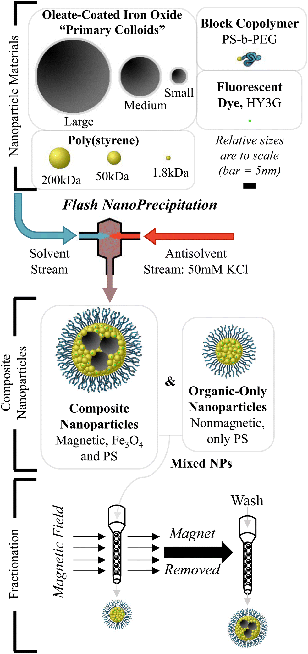 | ||
| Fig. 1 Production of composite nanoparticles. Flash NanoPrecipitation is used to produce composite organic–inorganic NPs composed of colloidal hydrophobic iron oxide, hydrophobic poly(styrene) (PS), hydrophobic Hostasol Yellow 3G (HY3G) dye, and amphiphilic block copolymer poly(styrene)-block-poly(ethylene glycol) (PS-b-PEG). “Empty” NPs with only polymer and organic dye can form under some conditions. These particles are separated by a magnetic fractionation step followed by composition analysis to determine what FNP operating parameters produce stoichiometric composite NPs or nonstoichiometric “empty” NPs. | ||
NPs are dialyzed against deionized MilliQ-grade water (17.9 to 18.2 MΩ cm) using 6–8 kDa MWCO regenerated cellulose dialysis tubing (Repligen; Waltham, MA) to remove residual THF and KCl. Typical dialysis conditions are 10 mL of NP dispersion dialyzed against 1000 mL of external water, with 8 changes of the external dialysis media over 24 hours. Dialyzed NPs are then measured by dynamic light scattering (DLS, Zetasizer ZS, Malvern Panalytical; Malvern, United Kingdom). All NPs are measured at 0.1 mg mL−1 concentration by dilution in deionized water for DLS measurements in triplicate using automatic software analysis parameters in general analysis mode with an NNLS-constrained particle size distribution algorithm.
2.6. Magnetic separation & compositional characterization
NPs were magnetically separated using a Miltenyi Biotec LS magnetic bead capture column using a MidiMACS external, permanent magnet (Miltenyi Biotec; Bergisch Gladbach, North Rhine-Westphalia, Germany). Magnetic fractionation is performed by loading a dry LS column into the magnet followed by addition of 2 mL of dialyzed NP dispersion as depicted schematically in Fig. 1. The magnetically captured NPs are washed with an additional 2 mL of deionized water twice to elute nonmagnetic NPs in the dispersion, with the eluted liquid from both the 2 mL loaded dispersion and the 4 mL of wash collected as the “nonmagnetic” fraction. The LS column is then removed from the magnetic field and the “magnetic” fraction is eluted by washing the column with 2 mL of deionized water. Each “magnetic” and “nonmagnetic” fraction was also analyzed by DLS for NP hydrodynamic size.Magnetic and nonmagnetic fraction composition was determined from optical measurements of iron oxide concentration by absorbance on the aqueous dispersions and HY3G concentration by fluorescence after extraction with DMF solvent. Concentration determination for iron oxide primary colloids is based on 400 nm absorbance measurements where there is some background particle scattering, however the iron oxide molar extinction is much larger and dominates the signal (see ESI,† Section S1 and Fig. S1, S2) of the absorbance measurement. HY3G concentration was determined by extracting 100 μL of dispersion in 900 μL of DMF and measuring HY3G fluorescence (excitation 458 nm, emission 510 nm). All polymer species are soluble in DMF while the oleate-coated iron oxide primary colloids are not dispersible in DMF; dilution in DMF dissolves the fluorescent dye and precipitates the strongly absorbing iron oxide which allows measurement of only the HY3G concentration. HY3G is a proxy for the hydrophobic polymer, due to the high solubility of the dye in the polymer.41 Fluorescence intensity is readily converted to concentration using a calibration curve of HY3G dissolved in 10:90 water:DMF solvent. All absorbance and fluorescence measurements were performed on a SpectraMax i3x plate reader (Molecular Devices, San Jose, CA) using a quartz, solvent-resistant plate. Selected NPs were prepared for TEM analysis by lyophilizing NP dispersions on flat carbon TEM grids as previously described for imaging with a Talos F/X 200 S/TEM microscope with NPs stained by ruthenium tetroxide vapors to make the PS domains visible alongside the iron oxide primary colloids.45
3. Results & discussion
We present the results in five sections: (1) characterization of the iron oxide primary colloids, (2) sizes of the composite NPs, magnetic fractions, and the nonmagnetic fractions as a function of feed compositions, (3) compositions of the magnetic and nonmagnetic NP fractions in terms of the ratio of organic to inorganic components, (4) TEM analysis of the inorganic colloids in the NP cores, and finally (5) the model of the assembly process that accounts for the diffusion limited aggregation of unequal sized species, based on a characteristic time scale for colloidal diffusion.3.1. Iron oxide primary colloids
Iron oxide colloids were produced in three different sizes as primary colloids for encapsulation into larger, composite NPs containing organic small molecules and polymers. Use of a high-temperature thermal decomposition method afforded high quality Fe3O4 particles with monodisperse average diameters adjustable from 5.5 nm to 28.7 nm, as shown in Fig. 2, with strongly adsorbed oleate coatings. The size distribution histograms in Fig. 2 show that each size classification of iron oxide primary colloid has negligible overlap with other distributions, allowing independent interrogation of iron oxide size effects on NP formation. Functional biomedical colloids are commonly encountered over this full size range due to the linkage between colloidal dimensions and electromagnetic properties. The dense oleate coating (quantified by thermogravimetric analysis, ESI,† Section S2 and Fig. S3–S5) renders these colloids dispersible in solvents such as hexane, ethyl acetate, toluene, and tetrahydrofuran (THF). Notably, acetone and N,N-dimethylformamide are not dispersants for these colloids but are solvents for the polymer and dye components. The increasing diameter of the primary iron oxide colloid affects the overall density of the colloid due to the increasing size of the nanocrystal core relative to the constant-thickness oleate coating shell. From TGA measurements the small colloids are 48.5 ± 0.7 wt% iron oxide, the medium colloids are 62.4 ± 1.6 wt%, and the large colloids are 81.0 ± 2.5 wt% iron oxide. This gives the small, medium, and large iron oxide colloids a density of 1.56, 1.98, and 3.11 g mL−1 respectively as listed in Table S1 (ESI†). | ||
| Fig. 2 Characterization of iron oxide (Fe3O4) oleate-coated primary colloids prepared by high temperature thermal decomposition methods. The three sizes used are referred to as “small”, “medium”, and “large” due to their relative sizes to each other. (A)–(C) Representative TEM micrographs of each size group (50 nm white scale bar in each image). Quantities are reported as ±standard deviation of repeated measurements. (D) Histogram of counted particle diameters for each size group (bin width is 1 nm to smooth the collected data) of small (blue solid bars), medium (green crosshatched bars), and large (orange stippled bars). | ||
3.2. Sizes of the composite NPs, magnetic fractions, and nonmagnetic fractions
Composite NP hydrodynamic diameters are shown in Fig. 3 for each material combination at increasing total solids concentration fed into the CIJ mixer. Each panel corresponds to a combination of PS molecular weight (1.8, 50, or 200 kDa) with iron oxide primary colloids (small, medium, or large). All NPs are prepared with a mass ratio of 1:1:2 stabilizing block copolymer:PS homopolymer (with dye):iron oxide colloid. This composition mimics ratios of stabilizer, drug, imaging agent that have been used for theranostic applications and maintains a high loading of the iron oxide primary colloids (50% by weight). Increasing the total solids concentration, at the same block copolymer to hydrophobic core ratio, produces larger NPs as has been demonstrated previously for NPs with homogeneous cores.37 Full NP size distributions are available in the (ESI,† Section S3 and Fig. S6–S8, Table S2) including tabulated full-width, half-maximum values for each distribution. The data in Fig. 3 is also presented in a compacted, stacked form in the ESI† (Fig. S9).
 | ||
| Fig. 3 Intensity-weighted average hydrodynamic diameters of NPs prepared by Flash NanoPrecipitation loaded with magnetic iron oxide colloids. Error bars on each symbol are ±standard deviation of triplicate replicates of the formulation. PS homopolymer and iron oxide primary colloid combinations are presented in a grid format with different total solids concentrations. Each individual plot contains the initial NP dispersion (solid triangles), the magnetically captured then released fraction (open squares) and the nonmagnetic fraction (open circles). | ||
Small and medium sized colloids combined with the 1.8 kDa and 50 kDa PS polymer produce monodisperse particles ranging from 40 to 130 nm. Large iron oxide colloids and 200 kDa PS homopolymer produce noticeably larger NPs in the size range of 150–280 nm, a size range where mononuclear phagocyte system recognition and clearance becomes a significant concern.1 The magnetic separation step classifies the initial NP dispersion into a similarly sized magnetic fraction and a smaller nonmagnetic fraction. For small iron oxide primary colloids, the nonmagnetic fraction is small (approximately 40 nm) and at low concentration, on average <3% of the organic polymers from HY3G fluorescence measurements. For medium and large iron oxide primary colloids, the nonmagnetic fraction is larger than 40 nm with a significant concentration of the organic species but smaller than the size of the magnetic fraction or the initial combined dispersion.
3.3. Stoichiometric nanoparticles: composition of magnetically separated NPs
Each NP formulation underwent magnetic fractionation to separate magnetically responsive composite NPs and nonmagnetic, organic-only NPs. Each magnetic or nonmagnetic fraction was then analyzed for the quantity of iron oxide primary colloids and HY3G hydrophobic dye it contained. Fig. 4 shows this data normalized as the percent of each quantity “captured” or detected in the magnetic fraction based on the volume and concentration in both fractions (eqn (1)). Iron oxide primary colloids are always highly retained in the magnetic fraction, over 90% in all cases. Our threshold criterion of “complete” capture of either the iron oxide colloids or HY3G dye in any fraction is 90%. Individual NPs may have different compositions or small quantities of nonmagnetic “nonstoichiometric” NPs may exist in formulations that are otherwise labelled stoichiometric by this 90% capture criterion. | (1) |
 | ||
| Fig. 4 Capture efficiency of iron oxide and fluorescent dye Hostasol Yellow 3G (HY3G) following magnetic separation. In all cases, the iron oxide is highly retained (dashed line on both figures indicates this 90% threshold for “complete” capture) in the magnetically captured fraction. HY3G capture efficiency varies significantly with the polymer molecular weight and the iron oxide primary colloid size combination. Small iron oxide primary colloids form homogeneous composite NPs with all molecular weights of core poly(styrene) while the medium iron oxide colloids require 50 kDa or 200 kDa poly(styrene) and large iron oxide colloids do not readily form homogeneous NP populations. Material that is not captured is in the nonmagnetic NP fraction. | ||
HY3G capture efficiency varies widely with the iron oxide primary colloid size and co-core PS molecular weight. Small primary colloids produce stoichiometric composite NPs that efficiently co-encapsulate the organic components and iron oxide colloids. HY3G capture is above the 90% threshold value for “complete” capture in all combinations of PS molecular weight and feed stream concentrations. Conversely, the large iron oxide primary colloids have no compositions that produce an HY3G capture efficiency above 90% because significant quantities of dye and polymer escape in the nonmagnetic fraction when attempting to make composite NPs with a large inorganic primary colloid. The medium sized primary colloids present an intermediate case, where using a low molecular weight PS (1.8 kDa) yields particles with poor HY3G capture, <60%, while using higher molecular weight PS (50 or 200 kDa) yields good HY3G capture, >90%. The strong DLS scattering intensity and large nonmagnetic fraction diameters for the large iron oxide primary colloids show that poorly matched core materials produce a large quantity of polymer-only, nonmagnetic NPs; between 50% and 80% of HY3G is lost to the nonmagnetic fraction in all cases with the large primary colloids. Large colloids suffer due to a pinch point in the FNP operating map that produces nonstoichiometric NP dispersions. Attempting to make composite NPs with large primary colloids requires high feed concentrations and high molecular weight homopolymer that increases NP size an undesirable amount, approaches the overlap concentration of the homopolymer above which FNP cannot be used,37 and ultimately cannot produce a stoichiometric composite NP dispersion with primary colloids co-encapsulated alongside organic species.
3.4. TEM analysis of composite NPs
Direct examination of the composite NPs by TEM enables quantification of the distribution of iron oxide primary colloids in the NP cores. PS can be readily stained with RuO4 vapor to provide a hierarchy of contrasts: the stained PS core will be visible against the carbon grid background while the strongly scattering (and magnetized, beam-deflecting) iron oxides will be visible against the stained PS. This presents as a light, circular PS “shadow” that defines the size of the hydrophobic NP core and darker, smaller primary iron oxide colloids within this boundary. The diameter of the hydrophobic core and the number of encapsulated iron oxide primary colloids per composite NP were determined for each different sized primary colloid and PS molecular weight combination. All TEM-examined samples are the 8 mg mL−1 feed concentration (2 mg mL−1 PS-b-PEG, 2 mg mL−1 PS, and 4 mg mL−1 iron oxide colloids) and are stained with ruthenium tetroxide. Representative TEM micrographs for each size iron oxide primary colloid and 1.8 kDa PS homopolymer are shown in Fig. 5, where every individual micrograph has a white 20 nm scale bar. Penetration of the electron beam through the NP specimens means that micrographs are 2D projections of the 3D distribution of colloids within the NP core. Similar images for the 50 kDa and 200 kDa PS homopolymer are available in the ESI† (Fig. S10 and S11) and are qualitatively similar. No distinct nonmagnetic NPs were observed for the small iron oxide primary colloid formulations, which is consistent with the weak DLS signal and low organic polymer concentration measured in the nonmagnetic fraction. Nonmagnetic nanoparticles are clearly visible for the medium and large iron oxide colloid formulations, including a small number of sub-stoichiometric composite NPs that contain only one or two medium-sized iron oxide primary colloids. Primary colloid aggregation number histograms are provided in the (ESI,† Section S4 and Fig. S12–S14) for each formulation. These histograms are coplotted with a Poisson distribution where the Poisson parameter, λ, is close to the average primary colloid aggregation number, but larger NP cores also exist which this distribution cannot accurately capture. | ||
| Fig. 5 Representative TEM micrographs and particle microstructures with 1.8 kDa PS homopolymer. All micrographs contain a white scale bar of 20 nm. The nonmagnetic fraction of the small iron oxide primary colloids produced TEM grids without observable NPs as indicated by the not detected (N.D.) annotation. The nonmagnetic fraction of the medium iron oxide primary colloids contained a small number of NPs with 1 or 2 primary colloids embedded, indicating some breakthrough during the magnetic separation. The large iron oxide primary colloids produced a nonmagnetic fraction without any observed iron oxide colloids with polymer-only NPs. TEM micrographs of composite NPs made with 50 kDa and 200 kDa PS homopolymer are available in the ESI† (S4 and Fig. S10 and S11). | ||
Quantitative analysis of NP sizes and aggregation number of the primary iron oxide colloids is shown in Fig. 6. NP hydrophobic core diameter is determined by measuring the circular area of the PS shadow, and primary colloid aggregation number is determined by manually counting the number of visible colloids. This NP diameter is smaller than the equivalent DLS hydrodynamic measurement due to the collapsed PEG corona in the high vacuum TEM environment.45 Small primary colloids produce composite NPs containing more than 10 magnetic colloids per NP. Medium and large primary iron oxide colloids have a much lower aggregation number than the small primary colloids, typically less than 10 magnetic colloids per NP. The decreased aggregation number with increasing primary colloid size is an expected geometric consequence of the fixed feed mass concentrations, where the number density will decrease with increasing primary colloid diameter and specific mass. Nonmagnetic NPs are observed for formulations using the medium and large sized iron oxide primary colloids, including breakthrough in the low-field magnetic separation of hydrodynamically large composite NPs loaded with only 1 or 2 medium sized primary colloids.
 | ||
| Fig. 6 NP composition after magnetic fractionation from inspected TEM images where the number of iron oxide primary colloids is counted in each observed NP. The ruthenium tetroxide stain renders the poly(styrene) visible, allowing for an NP diameter to be clearly defined for each analyzed NP. NPs from the magnetic fraction are represented by cross symbols while the nonmagnetic fraction NPs are represented by open circles on each plot. No nonmagnetic NPs were clearly observed with the small primary colloids. | ||
Fig. 6 shows signs of degeneracy in the aggregation number as similarly sized NPs have a different number of primary colloids co-encapsulated. This clearly shows some degree of microscale heterogeneity or fluctuation from a stoichiometric composition, also seen in Fig. 5, that becomes more evident as primary colloid size increases. Stoichiometric NP dispersion formulations (all small iron oxides and medium iron oxide with 50 kDa or 200 kDa PS) show a proportional trend between aggregation number and NP diameter (with clustered, overlapping symbols in a linear trend) while nonstoichiometric NP formulations show a collapsed or degenerate relationship between diameter and aggregation number. The stoichiometric dispersions show some degeneracy too with at most a 20 nm difference between the smallest and largest NP encapsulating the same number of primary colloids, and some of this may be due to the 2D projection of the TEM images and associated miscounting of the actual number of primary colloids. Nonstoichiometric dispersions have a much larger diameter span, 50 to 100 nm, between NPs encapsulating the same number of primary colloids showing that the composition of a single NP varies much more in these systems. Fig. 6 is also shown in the ESI† as a heat map to better convey the density of overlapping symbols (Fig. S15, ESI†). The magnetic separation step is a population-level screen of composite NPs based on magnetic susceptibility. Small variation in colloid aggregation number and relative primary colloid mass per composite NP does not adversely impact the magnetic capture properties of the stoichiometric NP dispersions.
3.5. Diffusion time scale model
Flash NanoPrecipitation is a bottom-up assembly of NPs from individual components driven by precipitation of hydrophobic species and adsorption of stabilizing amphiphiles. Aggregation is broadly characterized by two models describing how particle collisions lead to aggregate growth: diffusion-limited aggregation (DLA) or reaction-limited aggregation (RLA). DLA is a limiting case where all particle collisions are productive and yield aggregates, while RLA imposes a probabilistic constraint where only some fraction of collisions are productive and yield aggregates. There are several hydrophobic species here: PS polymer, HY3G dye, and oleate-coated iron oxide primary colloids which are expected to precipitate and form NP cores in a DLA manner because of the irreversible nature of hydrophobic surface contact in the aqueous antisolvent. HY3G is dilute, small, and soluble in the PS so it is neglected from subsequent component calculations as being part of the PS globules. The amphiphilic PS-b-PEG stabilizer is expected to adsorb onto these hydrophobic species, and their aggregates, in an RLA manner because only collisions against the collapsed PS globule of the PS-b-PEG will be productive and attach the block copolymer to the surface.37,46 The PS chains rapidly collapse as solvent quality changes, with typical polymer Zimm relaxation times (τZimm = ηRg3/kBT) or polymer collapse times on the order of 1 to 10 nanoseconds47 for the different poly(styrene) molecular weights used here. The transition from solvated polymer coils to collapsed polymer globules (Fig. 7A and B) is fast compared to both the Kolmogorov mixing time scale48 (∼3 ms) and the diffusion time scale for PS globules (10 to 1000 μs from eqn (4) below). Composite NPs form through aggregation of collapsed polymer globules (having HY3G dye dissolved in the PS) with each other and with the hydrophobic, oleate-coated iron oxide primary colloids. This composite hydrophobic core is stabilized by adsorption of block copolymer, with the collapsed PS block anchoring the PS-b-PEG. | ||
Fig. 7 Schematic 2-dimensional representations of spacing between colloidal species in dispersion. (A) Initial solution-dispersion of iron oxide primary colloids (black spheres), poly(styrene) homopolymer (yellow ribbons), and poly(styrene)-block-poly(ethylene glycol) block copolymers (blue-yellow ribbon) in tetrahydrofuran. All polymers are dissolved as coils in a good solvent in this state. (B) After mixing in Flash NanoPrecipitation, beyond the Kolmogorov time scale of about 3 ms for a CIJ mixer, the hydrophobic polymer species are collapsed as hydrophobic globules while the hydrophilic poly(ethylene glycol) remains a solvated coil. The arrow pointing to the dashed line indicates an average distance to a nearest neighbor between homopolymer, block copolymer, and iron oxide primary colloids. (C) and (D) Schematic representation considering distances between iron oxide (C) and poly(styrene) (D) species alone, which removes the consideration of collisions between particles of different types as shown in panel (B). The surface-to-surface separation, h, is then as defined for a single species  . . | ||
Composite NP assembly can be modeled by considering the diffusion time scale for each component that aggregates to form the hydrophobic core. The block copolymer occupies a large volume, compared to collapsed PS globules, due to the solvated coil of the PEG block as graphically depicted in Fig. 7B. Neglecting this RLA-adsorbing block copolymer allows a purely DLA-based approach to the core assembly model driven by diffusion time scales of the aggregating hydrophobic species. A characteristic time scale for individual species to diffuse and aggregate depends both on the species diffusivity and distance separating the species. Diffusivity,  , of species i is determined from Stokes–Einstein (eqn (2)) where kB is Boltzmann's constant, T is absolute temperature, η is the solvent viscosity, and Ri is the radius of species i. Surface-to-surface separation is considered on a per-component basis (the diagonal elements in a component matrix). In a mixed dispersion of PS and iron oxide colloids, there are pairwise interactions that can occur between PS globules and iron oxide primary colloids (the nondiagonal elements in a component matrix). The following analysis considers a simplified model where the DLA assembly of each hydrophobic core component, PS globules or iron oxide primary colloids, is considered with only homotypic interactions between each component. This is shown schematically in Fig. 7C and D where the mixture of species in Fig. 7B is reduced to considering only pairwise interactions between the same species, without the effect of the others. The two major factors motivating this decision are the desire both to produce an analytical, closed-form model for predicting relative diffusion-aggregation times which is computationally tractable (a 100 nm diameter NP contains over 90000 individual 1.8 kDa PS homopolymer chains which frustrates efforts to perform explicit population balances) and to enable simple analysis of the NP assembly time scale in the limiting case where only PS globules assemble to produce nonstoichiometric dispersions with NPs devoid of co-encapsulated primary colloids.
Particle surface-to-surface distance, hi, (eqn (3)) depends on ϕi the particle volume fraction where ϕi ≈ Ci/ρi (the ratio of species mass concentration to species density), and ϕmax the maximum close-sphere volume packing fraction (0.64 for homogeneous spheres). A characteristic time scale, τi, (eqn (4)) can then be calculated from the surface-to-surface spacing squared divided by the diffusivity for each species. Time scales for the materials used to prepare NPs are plotted in Fig. 8 on top of a general heatmap of values calculated from eqn (4) where the diffusion time scale is a function of the concentration and hydrodynamic radius. A full derivation of this model is presented in the (ESI,† Section S5 with graphical depictions in Fig. S15 and S16). This model determines only the diffusion-aggregation time scale for two components of the same type in the feed stream and it ignores the true multicomponent nature of the feed with heterotypic aggregation interactions between DLA-aggregating PS globules and iron oxide primary colloids with RLA-adsorbing block copolymer. A modified model for multicomponent interactions which calculates the average species-to-species separation (ESI,† Section S5 and eqn (S15)–(S20)) may produce a more realistic estimate of the diffusion-aggregation time scales but comes at the expense of yielding only an implicit solution. The characteristic diffusion-aggregation time scale for each species in this multicomponent model scales with the inverse diffusivity of the species because all surface-to-surface distances are reduced to one average value which obscures the effect of concentration on the characteristic diffusion aggregation time.
 | (2) |
 | (3) |
 | (4) |
 | ||
| Fig. 8 Diffusion time scale model for NP components. Heatmap is plotted from eqn (4) with lines of fixed characteristic diffusion time provided for clarity. The time scale is calculated using the hydrodynamic radius and interparticle spacing of PS globules and iron oxide primary colloids as NP growth begins in FNP. Over time, cores grow larger in size and become slower-diffusing, allowing PS-b-PEG block copolymer to stabilize the surface and arrest particle growth at small, NP-scale diameters. The concentration, time, and hydrodynamic diameter space is bounded at the upper limits by the PS overlap concentrations (c*), the Kolmogorov mixing time scale (τK), and the CIJ mixer residence time. The black arrow under the assembly schematic shows the point at which this model considers spacing between components. | ||
The characteristic time scales calculated from eqn (4) represent the initial assembly steps in FNP. As hydrophobic cores grow larger, the characteristic time for hydrophobic surfaces to aggregate increases as a larger aggregate radius leads to longer time between collision events in eqn (4). This time scale is analogous to the Smoluchowski kinetics time constant,26,33τs = 3η/4kBT[P]0 where [P]0 is the initial number density of a given species and η is the solvent viscosity, demonstrating that smaller, higher number density species have a smaller initial characteristic time scale for aggregation. TEM inspection and compositional measurements demonstrate that 1.8 kDa PS and small iron oxide primary colloids produce stoichiometric composite NPs. The characteristic time scales appear widely different from 0.005 ms for these PS globules to 0.1 ms for the iron oxide primary colloid, calculated from eqn (4), due to the different hydrodynamic sizes and surface-to-surface separation distances. However, these time scales only reflect monomer-to-monomer addition in the initial aggregation events. Aggregating PS globules increase in size (Raggregate = RinitialN1/3, where N is the number of PS globules in one aggregate) which lowers the diffusivity, slows the growth of PS aggregates, and provides a window of opportunity for the assimilation of small, growing PS aggregates and slower-diffusing iron oxide colloids into one growing NP core before PS-b-PEG stabilizes the NP growth and stops further addition of hydrophobic species.
The important metric when comparing the characteristic time scales is the ratio of time scales between the different NP core components in eqn (5). This time scale ratio and the % HY3G captured in the magnetic fraction are plotted against each other in Fig. 9. A clear dividing line between efficient stoichiometric NP production (% HY3G captured >90%) exists when the ratio of characteristic time scales is below a critical value of 30, τFeOx/τPS ≤ 30, showing that stoichiometric NP dispersions can be prepared without the need to exactly match the diffusion-aggregation time scales of the homopolymer and primary colloid components. Utilizing a higher molecular weight PS (50 kDa or 200 kDa) with medium size iron oxide primary colloids satisfies this design rule and produces stoichiometric composite NPs by increasing the characteristic time scale for aggregation of the PS globules. Large sized iron oxide primary colloids never satisfy this design rule and never produce stoichiometric composite NPs because of the formation of polymer-only NPs in the spaces between these large, slow-diffusing primary colloids. Block copolymer adsorption also occurs on a finite timescale and a sufficiently dense polymer layer will block the addition of additional hydrophobic species to the protected core. This suggests that individual components must diffuse faster than this hidden block copolymer adsorption time scale, which is at least 5 ms in this system based on the failure of even the most concentrated (shortest characteristic time scale) large iron oxide colloid condition to form stoichiometric dispersions when approaching the τFeOx/τPS ≤ 30 threshold. Increasing the block copolymer molecular weight, which is not studied here, is expected to delay this block copolymer adsorption time scale and likely would relax this assembly criteria. Dilute (2 mg mL−1) large primary colloids also show characteristic diffusion time scales longer than the average CIJ mixer residence time which shows fundamental restrictions on stoichiometric encapsulation of large primary colloids due to low diffusivity and low number density. Satisfying this critical time scale ratio requirement and the secondary maximum allowable diffusion time scale limit serves as general design rules for composite NP formulations prepared by Flash NanoPrecipitation, independent of any assumptions about the identity of the aggregating species.
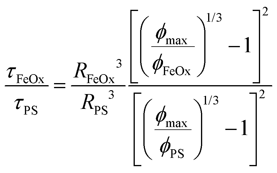 | (5) |
 | ||
| Fig. 9 Combined plot of characteristic time scale ratio and capture efficiency. The characteristic diffusion time scale ratio is τFeOx/τPS from eqn (5). Coordinates of these datapoints are a combination of the data calculated in Fig. 8 for characteristic diffusion time scales and measured HY3G capture efficiency in Fig. 4. The vertical dashed line is the 90% threshold for “complete” capture of all HY3G in the magnetic fraction. This corresponds to a time scale ratio at or below 30, suggesting that this is a critical value for stoichiometric NP formation. | ||
4. Conclusions
NP hydrodynamic diameter is a primary particle characteristic that must be within specified limits for most applications. Particulate sizes determine gross biodistribution in biomedical applications and NPs between 20 and 150 nm are desirable due to long circulation times and tunable accumulation in target tissues including tumors. The relatively new field of theranostic nanoparticles involves the co-encapsulation of an imaging agent to track the fate of NPs along with the therapeutic active agent. Inorganic colloidal nanocrystals have been used as stable, long-lasting imaging agents including superparamagnetic iron oxide particles for MRI or MPI imaging, quantum dots for fluorescence imaging, and gold particles for CT imaging. Composite nanoparticles combine these inorganic colloids with organic therapeutics and structural polymers to readily produce theranostic composite nanoparticles. A key question for composite NPs in this application is whether the colloid and therapeutic are stoichiometrically co-encapsulated in all NPs in the population. If a large fraction of the NPs excludes the inorganic colloids, then the colloid-generated imaging signal is not correlated with the therapeutic agent delivery.A major challenge in previous efforts to produce composite NPs is the separation of low molecular weight organics and large, inorganic colloids into different discrete NP populations with nonstoichiometric co-encapsulation.33 In this contribution we have used Flash NanoPrecipitation (FNP) to produce composite NPs and analyze the conditions that produce stoichiometric or nonstoichiometric NP dispersions. The use of superparamagnetic iron oxide primary colloids of three sizes (5.5 nm, 15.3 nm, and 27.8 nm average diameters) and different molecular weight poly(styrene) polymers (1.8 kDa, 50 kDa, and 200 kDa) has enabled quantification of the criteria that are required to obtain composite NPs that stoichiometrically co-encapsulate both species within desirable overall NP hydrodynamic size limits. NP formulations prepared with different sized primary colloids and hydrophobic PS molecular weights were fractionated by a magnetic capture column, sorting composite NPs by magnetic susceptibility. The composition of the magnetic and nonmagnetic fractions was quantified by measuring the organic and inorganic component concentrations and by direct TEM examination. The extensive, quantitative data obtained enables the testing of a mathematical model of the diffusion-aggregation time scales during the assembly of nanoparticle cores.
Stoichiometric composite NPs form when the ratio of characteristic diffusion-aggregation time scales between the primary colloids and the organic, hydrophobic species is under a critical ratio of 30, τcolloid/τorganic ≤ 30. When diffusion time scales are mismatched by more than this quantity, or when large colloids with exceptionally long diffusion time scales (>5 ms) are used, significant quantities (40% to 80%) of the organic species are lost into a NP population that excludes the inorganic colloids. Increasing the size and the hydrophilic block fraction of the stabilizing block copolymer will slow the rate of block copolymer addition, which may better facilitate the encapsulation of large primary colloids. This predictive design rule for creating stoichiometric composite NPs using Flash NanoPrecipitation is based on a simple diffusion time scale argument which can be readily calculated for any generic species. This model enables rational design of NPs with limited experimental exploration required for new material combinations in novel composite NPs with a large variety of potential colloidal cargoes including hydrodynamically large biopolymers like messenger RNA transcripts or coiled DNA plasmids.
Data availability
The data supporting this article have been included as part of the ESI.†Conflicts of interest
There are no conflicts of interest to declare.Acknowledgements
This work was supported by the National Science Foundation Graduate Research Fellowship under Grant No. DGA 1148900. The authors acknowledge the use of Princeton's Imaging and Analysis Center, which is partially supported through the Princeton Center for Complex Materials (PCCM), a National Science Foundation (NSF)-MRSEC program (DMR-2011750).References
- E. Blanco, H. Shen and M. Ferrari, Nat. Biotechnol., 2015, 33, 941–951 CrossRef CAS PubMed.
- M. Longmire, P. L. Choyke and H. Kobayashi, Nanomedicine, 2008, 3, 703–717 CrossRef CAS PubMed.
- A. C. Anselmo, V. Gupta, B. J. Zern, D. Pan, M. Zakrewsky, V. Muzykantov and S. Mitragotri, ACS Nano, 2013, 7, 11129–11137 CrossRef CAS PubMed.
- H. M. Patel and S. M. Moghimi, Adv. Drug Delivery Rev., 1998, 32, 45–60 CrossRef PubMed.
- A. E. Nel, L. Mädler, D. Velegol, T. Xia, E. M. V. Hoek, P. Somasundaran, F. Klaessig, V. Castranova and M. Thompson, Nat. Mater., 2009, 8, 543–557 CrossRef CAS PubMed.
- K. Xiao, Y. Li, J. Luo, J. S. Lee, W. Xiao, A. M. Gonik, R. G. Agarwal and K. S. Lam, Biomaterials, 2011, 32, 3435–3446 CrossRef CAS PubMed.
- S. K. Lai, Y.-Y. Wang and J. Hanes, Adv. Drug Delivery Rev., 2009, 61, 158–171 CrossRef CAS PubMed.
- K. Maisel, L. Ensign, M. Reddy, R. Cone and J. Hanes, J. Controlled Release, 2015, 197, 48–57 CrossRef CAS PubMed.
- S. M. D’Addio, W. Saad, S. M. Ansell, J. J. Squiers, D. H. Adamson, M. Herrera-Alonso, A. R. Wohl, T. R. Hoye, C. W. Macosko, L. D. Mayer, C. Vauthier and R. K. Prud’homme, J. Controlled Release, 2012, 162, 208–217 CrossRef PubMed.
- L. Babes, B. Denizot, G. Tanguy, J. J. Le Jeune and P. Jallet, J. Colloid Interface Sci., 1999, 212, 474–482 CrossRef CAS PubMed.
- Z. W. Tay, P. Chandrasekharan, A. Chiu-Lam, D. W. Hensley, R. Dhavalikar, X. Y. Zhou, E. Y. Yu, P. W. Goodwill, B. Zheng, C. Rinaldi and S. M. Conolly, ACS Nano, 2018, 12, 3699–3713 CrossRef CAS PubMed.
- H. Xu, T. Song, X. Bao and L. Hu, J. Magn. Magn. Mater., 2005, 293, 514–519 CrossRef CAS.
- A. E. Deatsch and B. A. Evans, J. Magn. Magn. Mater., 2014, 354, 163–172 CrossRef CAS.
- J. F. Hainfeld, D. N. Slatkin, T. M. Focella and H. M. Smilowitz, Br. J. Radiol., 2006, 79, 248–253 CrossRef CAS PubMed.
- D. A. Giljohann, D. S. Seferos, W. L. Daniel, M. D. Massich, P. C. Patel and C. A. Mirkin, Angew. Chem., Int. Ed., 2010, 49, 3280–3294 CrossRef CAS PubMed.
- L. L. Ma, M. D. Feldman, J. M. Tam, A. S. Paranjape, K. K. Cheruku, T. A. Larson, J. O. Tam, D. R. Ingram, V. Paramita, J. W. Villard, J. T. Jenkins, T. Wang, G. D. Clarke, R. Asmis, K. Sokolov, B. Chandrasekar, T. E. Milner and K. P. Johnston, ACS Nano, 2009, 3, 2686–2696 CrossRef CAS PubMed.
- L. Y. Ang, M. E. Lim, L. C. Ong and Y. Zhang, Nanomedicine, 2011, 6, 1273–1288 CrossRef PubMed.
- J. Hampl, M. Hall, N. A. Mufti, Y. M. Yao, D. B. MacQueen, W. H. Wright and D. E. Cooper, Anal. Biochem., 2001, 288, 176–187 CrossRef CAS PubMed.
- K. Welsher and H. Yang, Nat. Nanotechnol., 2014, 9, 198–203 CrossRef CAS PubMed.
- R. Bilan, I. Nabiev and A. Sukhanova, ChemBioChem, 2016, 17, 2103–2114 CrossRef CAS PubMed.
- B. R. Liu, Y. Huang, J. G. Winiarz, H.-J. Chiang and H.-J. Lee, Biomaterials, 2011, 32, 3520–3537 CrossRef CAS PubMed.
- G. Ruan and J. O. Winter, Nano Lett., 2011, 11, 941–945 CrossRef CAS PubMed.
- J. Ge, M. Lan, B. Zhou, W. Liu, L. Guo, H. Wang, Q. Jia, G. Niu, X. Huang, H. Zhou, X. Meng, P. Wang, C.-S. Lee, W. Zhang and X. Han, Nat. Commun., 2014, 5, 4596 CrossRef CAS PubMed.
- S. Jung and X. Chen, Adv. Healthcare Mater., 2018, 7, 1800252 CrossRef PubMed.
- B. Ungun, R. K. Prud’homme, S. J. Budijono, J. Shan, S. F. Lim, Y. Ju and R. Austin, Opt. Express, 2009, 17, 80–86 CrossRef CAS PubMed.
- M. E. Gindy, A. Z. Panagiotopoulos and R. K. Prud’homme, Langmuir, 2008, 24, 83–90 CrossRef CAS PubMed.
- J. Zhu and R. C. Hayward, J. Am. Chem. Soc., 2008, 130, 7496–7502 CrossRef CAS PubMed.
- J. Bae, J. Lawrence, C. Miesch, A. Ribbe, W. Li, T. Emrick, J. Zhu and R. C. Hayward, Adv. Mater., 2012, 24, 2735–2741 CrossRef CAS PubMed.
- K. D. Mahajan, Q. Fan, J. Dorcéna, G. Ruan and J. O. Winter, Biotechnol. J., 2013, 8, 1424–1434 CrossRef CAS PubMed.
- C. E. Markwalter, R. F. Pagels, B. K. Wilson, K. D. Ristroph and R. K. Prud’homme, JoVE, 2019, e58757 Search PubMed.
- H. M. Vishwasrao, A. M. Master, Y. G. Seo, X. M. Liu, N. Pothayee, Z. Zhou, D. Yuan, M. D. Boska, T. K. Bronich, R. M. Davis, J. S. Riffle, M. Sokolsky-Papkov and A. V. Kabanov, Chem. Mater., 2016, 28, 3024–3040 CrossRef CAS PubMed.
- H. D. Lu, S. S. Yang, B. K. Wilson, S. A. McManus, C. V. H.-H. Chen and R. K. Prud’homme, Appl. Nanosci., 2017, 7, 83–93 CrossRef CAS.
- N. M. Pinkerton, M. E. Gindy, V. L. Calero-DdelC, T. Wolfson, R. F. Pagels, D. Adler, D. Gao, S. Li, R. Wang, M. Zevon, N. Yao, C. Pacheco, M. J. Therien, C. Rinaldi, P. J. Sinko and R. K. Prud’homme, Adv. Healthcare Mater., 2015, 4, 1376–1385 CrossRef CAS PubMed.
- E. G. Fuller, H. Sun, R. D. Dhavalikar, M. Unni, G. M. Scheutz, B. S. Sumerlin and C. Rinaldi, ACS Appl. Polym. Mater., 2019, 1, 211–220 CrossRef CAS.
- E. G. Fuller, G. M. Scheutz, A. Jimenez, P. Lewis, S. Savliwala, S. Liu, B. S. Sumerlin and C. Rinaldi, Int. J. Pharm., 2019, 572, 118796 CrossRef CAS PubMed.
- J. Han, Z. Zhu, H. Qian, A. R. Wohl, C. J. Beaman, T. R. Hoye and C. W. Macosko, J. Pharm. Sci., 2012, 101, 4018–4023 CrossRef CAS PubMed.
- R. F. Pagels, J. Edelstein, C. Tang and R. K. Prud’homme, Nano Lett., 2018, 18, 1139–1144 CrossRef CAS PubMed.
- G. Ruan, D. Thakur, S. Deng, S. Hawkins and J. O. Winter, Proc. Inst. Mech. Eng., Part N, 2009, 223, 81–86 CrossRef.
- S. Sun, H. Zeng, D. B. Robinson, S. Raoux, P. M. Rice, S. X. Wang and G. Li, J. Am. Chem. Soc., 2004, 126, 273–279 CrossRef CAS PubMed.
- J. Park, K. An, Y. Hwang, J.-G. Park, H.-J. Noh, J.-Y. Kim, J.-H. Park, N.-M. Hwang and T. Hyeon, Nat. Mater., 2004, 3, 891–895 CrossRef CAS PubMed.
- V. Kumar, D. H. Adamson and R. K. Prud’homme, Small, 2010, 6, 2907–2914 CrossRef CAS PubMed.
- J. K. Beattie, A. M. Djerdjev and G. G. Warr, Faraday Discuss., 2009, 141, 31–39 RSC.
- J. K. Beattie, A. M. Djerdjev, A. Gray-Weale, N. Kallay, J. Lützenkirchen, T. Preočanin and A. Selmani, J. Colloid Interface Sci., 2014, 422, 54–57 CrossRef CAS PubMed.
- X. Yan, M. Delgado, J. Aubry, O. Gribelin, A. Stocco, F. Boisson-Da Cruz, J. Bernard and F. Ganachaud, J. Phys. Chem. Lett., 2018, 9, 96–103 CrossRef CAS PubMed.
- B. K. Wilson and R. K. Prud’homme, J. Colloid Interface Sci., 2021, 604, 208–220 CrossRef CAS PubMed.
- J. C. Cheng and R. O. Fox, Ind. Eng. Chem. Res., 2010, 49, 10651–10662 CrossRef CAS.
- T. I. Morozova and A. Nikoubashman, J. Phys. Chem. B, 2018, 122, 2130–2137 CrossRef CAS PubMed.
- B. K. Johnson and R. K. Prud’homme, AIChE J., 2003, 49, 2264–2282 CrossRef CAS.
Footnote |
| † Electronic supplementary information (ESI) available. See DOI: https://doi.org/10.1039/d4sm00935e |
| This journal is © The Royal Society of Chemistry 2024 |