
 Open Access Article
 This Open Access Article is licensed under a
 Creative Commons Attribution 3.0 Unported Licence
Transient intermediate in the formation of an amorphous metal–organic framework†
Adam F.
Sapnik
 a,
Michael F.
Thorne
a,
Celia
Castillo-Blas
a,
Luke
Keenan
b,
Timothy
Johnson
c and
Thomas D.
Bennett
*a
a,
Michael F.
Thorne
a,
Celia
Castillo-Blas
a,
Luke
Keenan
b,
Timothy
Johnson
c and
Thomas D.
Bennett
*a
aDepartment of Materials Science and Metallurgy, University of Cambridge, Cambridge, CB3 0FS, UK. E-mail: tdb35@cam.ac.uk
bDiamond Light Source Ltd, Diamond House, Harwell Campus, Didcot, Oxfordshire OX11 0DE, UK
cJohnson Matthey Technology Centre, Blount's Court, Sonning Common, RG4 9NH, UK
First published on 13th February 2024
Abstract
Amorphous metal–organic frameworks are rarely formed via direct synthesis. Our limited understanding of their atomic assembly in solution prevents full exploitation of their unique structural complexity. Here, we use in situ synchrotron X-ray absorption spectroscopy with sub-second time resolution to probe the formation of the amorphous Fe-BTC framework. Using a combination of spectral fingerprinting, linear combination analysis, and principal component analysis coupled with kinetic analyses, we reveal a multi-stage formation mechanism that, crucially, proceeds via the generation of a transient intermediate species.
Introduction
Structure–property relationships are fundamental to the study of metal–organic frameworks (MOFs). Understanding how a MOF forms enables us to take advantage of these relationships. This concept applies to both crystalline and amorphous MOFs; however, its implementation in the latter is stifled by a vastly increased degree of structural complexity. Amorphous MOFs are typically obtained from crystalline materials by applying heat or pressure. Far less commonly, they can be obtained through direct synthesis, avoiding transit of the crystalline state and the associated industrial cost of doing so.1,2 Despite the highly sought-after transport and catalytic properties of amorphous MOFs, their formation mechanisms remain an almost untouched area of research.3 This is particularly surprising given that, even in the crystalline-centric field of MOFs, research has noted numerous examples of amorphous intermediates observed during the formation of crystalline MOFs.1,2,4–6 Studies on the direct synthesis of amorphous MOFs have largely been avoided due to the challenges associated with characterising the structures of amorphous MOFs which are further amplified in solution studies where solvent is often present in a vast excess.The processes underpinning the formation of crystalline materials are very well-established. Crystallisation involves two key stages: nucleation and crystal growth.7 Nucleation marks the early stage of crystallisation, characterised by an increase in local density and the emergence of local ordering. Two primary types of crystal nucleation exist: classical and non-classical. Classical nucleation occurs when nuclei form through spontaneous fluctuations in a super-saturated solution, best explained by classical nucleation theory (CNT). A challenge for CNT is its inability to explain transient precursor phases observed before crystalline materials appear, including pre-nucleation clusters, structural building unit clusters, liquid-like phases, and amorphous phases. These processes can be described as non-classical nucleation.8 Transient amorphous intermediates may transform into crystalline material via internal restructuring, or they may act as a reservoir of monomers or as a potential site for heterogeneous nucleation to occur. However, experimental validation of non-classical routes can be challenging due to detection limits associated with pre-nucleation clusters in a solution.
Crystal growth is the latter stage of crystallisation, transforming these nucleated particles into stable crystalline products.7 Under supersaturation and equilibrium conditions, crystal growth is thermodynamically favoured, resulting in predictable morphologies that minimise the Gibbs surface free energy (Wulff construction). Energetics also drive the growth of larger particles at the expense of smaller ones in the process of Ostwald ripening. Many systems follow sequential pathways, nucleating at the lowest free energy phase and transforming to yield the thermodynamically stable product (Ostwald's rule of stages). These transformations may occur through dissolution–recrystallisation or solid-phase rearrangements. At present, it is not clear how our understanding of crystallisation may translate to the formation of amorphous phases. One key challenge is understanding how best to promote the nucleation of an amorphous phase and inhibit its subsequent crystallisation.
Fe-BTC, commercially available as Basolite® F300, is a widely studied amorphous MOF that has received significant industrial interest for its powerful catalytic ability and potential propane/propene separation behaviour.9,10 The local structure of Fe-BTC, studied using X-ray pair distribution function analysis and X-ray absorption spectroscopy, is formed from Fe3O trimer units wherein three Fe(III) ions are each octahedrally coordinated by four bridging carboxylate groups, one water or hydroxide molecule and one shared oxo-anion [Fig. 1a].11–14 These trimers assemble via the 1,3,5-benezentricarboxylate linker to form hybrid tetrahedra joined in a disordered fashion to form the Fe-BTC network [Fig. 1b]. We recently used scanning electron diffraction to reveal that these building units assemble to form a complex nanocomposite structure, comprising nanocrystallites embedded within a topologically disordered matrix that ultimately results in an amorphous scattering pattern.15
 | ||
| Fig. 1 (a) The Fe3O trimer unit and (b) hybrid tetrahedral building units of Fe-BTC. (c) Schematic of the formation of Fe-BTC; orange Fe(III) solution and trimesic acid solution are combined before observing an orange-to-green-to-yellow-to-orange colour change and an accompanying increase in viscosity. FeO6 octahedra (grey), O (red) and C (grey). H omitted for clarity. | ||
Fe-BTC can be obtained in the laboratory via a facile ambient condition synthesis within a matter of minutes.11,16,17 The resulting gel can be dried to obtain bulk, hierarchically porous, monolithic pieces known as aerogels. Fe-BTC aerogels have exhibited promising gas storage properties with both micro and macroporous textures, with BET surface areas over 1600 m2 g−1 and a total pore volume of 5.62 cm3 g−1.16 These monolithic materials are preferred over their powdered counterparts for industrial applications due to their robust mechanical properties; however, our fundamental understanding of them remains poor.18 The structure and morphology – and hence physical properties – of these materials are directly correlated to their syntheses and so a mechanistic understanding of the formation process is required to improve their properties.
Under harsh reaction conditions, such as high temperature or in the presence of HF acid, a crystalline MOF, MIL-100, can be obtained from similar synthesis solutions to Fe-BTC.19 MIL-100 has the same composition and local structure as Fe-BTC, but with a giant pore, crystalline, architecture, and has been widely studied for its applications in gas storage, biomedicine and environmental applications.20–22 Hence, Fe-BTC and MIL-100 represent different positions on the same energetic landscape. Given the chemical and structural similarity between Fe-BTC and MIL-100, there are likely to be parallels between their atomic-scale assembly. Indeed, the solid-state dry-gel transformation of Fe-BTC into MIL-100 has been reported by employing elevated temperatures, confirming their shared energetic landscape.23 The crystalline MIL-100 structure has been demonstrated to support a variety of other metal centres (such as Al, Cr, V, Sc, Ti, Mn, In and Ga) in addition to the Fe analogue.20,24–27 The formation of MIL-100 (Al) is reported to occur via successive formation of Al1BTC, Al2BTC and then Al2BTC2 intermediates, elucidated through in situ27Al NMR spectroscopy.28,29 However, it is known that the chemistry of Al and Fe in solution are quite different and so their mechanisms are likely to differ. In MIL-100 (Mn), it was found that in situ oxidation from Mn(II) to Mn(III) was a crucial step in the formation of the framework.25 Oxidation of Fe or Fe(II) reagents to Fe(III) has been noted as having an important “structure-directing effect” in several syntheses of MIL-100 (Fe).19,30–35 Another study, starting with an Fe(III) salt, noted the sensitivity of this system to solvent, with water leading to the formation of MIL-100 while an acetone/water mixture caused the formation of the MIL-45 polymorph.36 One of the most in-depth studies on the formation of MIL-100 (Fe) reported the isolation and characterisation of an Fe(II) intermediate, Fe3BTC2·xH2O, which we denote as Fe(II)-BTC, under an inert atmosphere.37 The Fe(II)-BTC intermediate was rapidly oxidised in air to form MIL-100 (Fe). They proposed the following overall chemical reaction:
| 3Fe2+ + 2BTC3− + xH2O → Fe3BTC2·xH2O Fe(II)-BTC formation | (1) |
| 4Fe3BTC2·xH2O + 3O2 → 4Fe3O(OH)(H2O)2BTC2 + (4x − 10)H2O Oxidation to MIL-100 | (2) |
Further characterisation of the intermediate was limited due to its highly air-sensitive nature. The average coordination environments around the Fe centres in Fe(II)-BTC and MIL-100 (Fe) are Fe(II)(H2O)4(φ1)1(φ2)1/2 and Fe(III)O(φ1)4(OH)1/3(H2O)2/3, respectively, where φ1 denotes the carboxylate group of the organic linker bonding in a bridging mode and φ2 represents a chelate mode [Fig. S1, ESI†].37 Amongst the known MIL-100 materials, it is Fe that has one of the lowest abundances of NMR-active nuclei (2.1%) and is, therefore, one of the most challenging members of this family to study.38 Despite this, it is surprising given the industrial significance and catalytic promise of Fe-BTC that its formation specifically has yet to be thoroughly investigated. More generally, there is a great scarcity of studies probing the formation of amorphous MOFs.
Here, we use in situ X-ray absorption spectroscopy to study the formation mechanism and kinetics of Fe-BTC for the first time. We employ a flow reactor to facilitate fast mixing of the reagents, in combination with rapid data acquisition times available at synchrotron facilities, enabling spectra to be collected with a time resolution of 0.5 s. We detect the presence of a transient intermediate in the formation of Fe-BTC and propose a simple mechanism based on our results. We conclude that Fe-BTC formation is characterised by slow, continuous nucleation and simultaneous, fast growth; the nucleation step itself is complex and is highly correlated with the formation of a transient intermediate.
Results and discussion
Fe-BTC was synthesised using an adapted method from ref. 11 where methanolic solutions of iron(III) nitrate and 1,3,5-benzenetricarboxylic acid were combined at room temperature to yield a viscous reaction mixture in a matter of minutes [Fig. 1c and Fig. S2, ESI†]. Upon addition of the metal source to the organic linker, an orange-to-green-to-yellow-to-orange colour change was observed within a few seconds. We hypothesised this was due to redox at the Fe centres; starting as Fe(III) in the reagent solution, forming a disordered Fe(II) complex analogous to Fe(II)-BTC, before being oxidised back to Fe(III) and forming Fe-BTC.30,37In situ reduction of Fe(III) during MIL-100 synthesis has previously been reported to occur via an acetone/water solvent pathway, while separate studies have shown Fe(III) to be reduced by ascorbic acid in an aqueous solution.36,39 Here, we speculate that reduction may occur via methanol or nitrate-based pathways, though further investigation is required to confirm this.35,36 The subsequent oxidation back to Fe(III) is expected to occur by reaction in air, as previously reported for MIL-100.30,37 No further colour changes were observed, though the solution increased in viscosity until it became non-flowing. Increasing the reactant concentration caused the rate of colour change and viscosity to increase. At the highest concentrations (employed in ref. 11), the Fe-BTC gel solidified instantly, and the colour change occurred almost immediately [Fig. S3, ESI†].Initially, the formation of Fe-BTC was probed using in situ UV-vis spectroscopy. To achieve measurable levels of absorption, the concentration of the reaction had to be significantly reduced, in turn decreasing the rate of the reaction [See Methods]. In situ data were collected for 45 min with a time resolution of 6 s [Fig. S4a, ESI†]. The first spectrum collected 12 s after mixing, had a maximum absorption at λmax = 350 nm. As the reaction progressed, the absorption at λ = 350 nm decreased in intensity, coupled with an increase in intensity at λ = 300 nm. Upon visual inspection of the data, changes in the spectra occurred more rapidly after mixing than later on. This was made clear by comparison of the first spectra collected from the in situ measurement (12 s after mixing) and a reference spectrum collected for iron(III) nitrate which indicated that appreciable changes occur even in the first 12 s of the reaction [Fig. S4b, ESI†]. The simultaneous decrease and increase in the absorbance can be attributed to an orange–colourless transition and the formation of Fe-BTC, respectively.30 Unfortunately, at this low concentration the colour change was not visibly apparent and hence it was challenging to determine when the reaction had gone to completion. Furthermore, at this low concentration, insufficient yield of Fe-BTC was obtained for further characterisation. Nonetheless, the results are consistent with Fe-BTC being formed, even at low concentration. Extracting the absorbance at both λ = 300 nm and λ = 400 nm confirmed that changes in the spectra occur more rapidly during the initial stages of the reaction. In later spectra, the absorbances begin to plateau suggesting the reaction is nearing completion [Fig. S4c, ESI†]. Determination of the derivative of the absorbance at λ = 300 nm and λ = 400 nm as a function of time, confirmed this decreasing rate of change [Fig. S4d, ESI†]. As a very coarse examination of Fe-BTC formation, these data suggest that structural transformations begin rapidly after mixing of the reagents.
In situ X-ray absorption spectroscopy data were collected at I20-EDE (Diamond Light Source, UK) to investigate the oxidation state and reaction kinetics of Fe-BTC formation.40 A peristaltic pump was used to circulate the methanolic iron(III) nitrate solution through a quartz capillary mounted in the path of the beam [Fig. S5, ESI†]. Data acquisition was started in transmission mode and a syringe pump was used to inject the linker solution after 20 s to initiate the reaction. The concentration and temperature of the solutions were necessarily reduced compared to those in ref. 11 to avoid blockages in the capillary and obtain an edge step close to unity [see Methods]. No noticeable radiation damage was observed between the starting solution and the final solution. Spectra were acquired with a time resolution of 0.5 s for 300 s at the Fe K-edge; the resulting 600 spectra were normalised in the DAWN software by fitting a linear polynomial to the pre-edge and a low-order polynomial to the post-edge region before flattening the spectra to obtain an edge-step of approximately one.41,42
A subset of the dataset is presented in Fig. 2a [see Fig. S6 for the full dataset, ESI†]. There was a negligible shift in the pre-edge, at 7116.0 eV, during the reaction [Fig. 2b]. The nature of the pre-edge, ascribed to the 1s → 3d transition, is indicative of an octahedral Fe coordination geometry throughout.12,43 The position of the rising edge varied throughout the reaction; initially, at 7126.7 eV, a shift of ΔE = −0.05 eV was observed 5 s after mixing, after which a gradual shift of ΔE = +0.5 eV was observed throughout subsequent measurements [Fig. 2c & Fig. S7, ESI†]. At the end of the reaction, the position of the rising edge was 7127.1 eV. Greater changes were seen in the higher energy region of the XANES, with a clear broadening of the peak initially centred around 7180 eV [Fig. 2d]. Finally, in the EXAFS region, a general shift to higher energy was observed in addition to noticeable changes in the structure of the absorbance [Fig. 2e].
 | ||
| Fig. 2 (a) In-situ X-ray absorption spectra, (b) pre-edge, (c) rising-edge (d) XANES and (e) EXAFS for the formation of Fe-BTC; addition of the linker occurs at t = 20 s. | ||
Comparison between the XANES data of the final Fe-BTC gel and the spectrum acquired for a solid pellet of Fe-BTC were almost identical, confirming the successful formation of Fe-BTC in situ, they are also in close agreement with previously reported data for Fe-BTC [Fig. S8, ESI†].12 Small differences observed in the peak intensities between Fe-BTC gel and powder can be attributed to the challenges of normalising data from inhomogeneous pellet samples compared to the reaction solution, in addition to the optimisation of the beamline for rapid in situ measurements and not high-resolution static measurements. Powder X-ray diffraction measurements comparing Fe-BTC obtained from the in-situ synthesis and the previously reported methods were almost identical [Fig. S9, ESI†].11
Comparison between the XANES region of the final Fe-BTC gel and several Fe standards confirmed the Fe(III) oxidation state, as expected for Fe-BTC [Fig. S10, ESI†].12 During the reaction, a shift in the position of the rising edge was observed, initially to lower energy (ΔE = −0.05 eV) and then towards higher energies (ΔE = +0.5 eV) [Fig. S11, ESI†]. The position of the rising edge for Fe(II) is lower than Fe(III) oxidation states, due to the reduced depth of the potential well towards the continuum at the lower oxidation state.41 Hence, the observed variation is consistent with the proposed rapid reduction of Fe(III) followed by subsequent oxidation to form Fe-BTC. Typically, the shift in edge position upon reduction is greater than we observed here. For example, a previous study on MIL-101 reported a decrease of 2–3 eV upon partial reduction of Fe(III) during Li+ intercalation.44 We ascribe the smaller change observed here to the competing effect of the simultaneous change in oxidation state and ligand environment at the Fe centres, which act to partially reduce the magnitude of the net shift in edge position. For a given Fe oxidation state, the position of the rising edge may lie within a 2–3 eV range when coordinated by different ligands [Fig. S12, ESI†]. It is pertinent to note that the measured methanolic iron(III) nitrate standard, existing predominantly as [Fe(OH)(H2O)5]2+ in solution, possessed one of the lowest energy edges of the six Fe(III) standards measured, with almost all other Fe(III) materials exhibiting rising edges at higher energies. In other words, while the reduction of Fe(III) to Fe(II) is expected to shift the edge to lower energies – which is indeed observed – the concurrent change in the ligand environment affects a comparable shift towards higher energies, resulting in a smaller than anticipated net shift towards lower energy. This will be further complicated by the presence of both Fe(II) and Fe(III) species, both of which will simultaneously contribute to the overall observed spectra.
The EXAFS region from a series of the spectra was transformed from energy to k-space up to 15 Å−1 and the Fourier transform was calculated to obtain a real-space map of the Fe scattering path lengths using the Athena software [Fig. 3a and b].45 The Fourier transform of χ(k) revealed a prominent peak from the first coordination shell Fe at 1.99 Å, from the Fe–O path length, which shifted towards 1.78 Å as the reaction progressed. Such variation is generally consistent with the transition from both Fe(II) and (III) being present earlier on to solely Fe(III) as the reaction proceeds and Fe-BTC is formed.46 Marked changes were observed beyond the first coordination sphere due to the transition from aqua-hydroxy species to the carboxylate-based Fe3O trimer motif in Fe-BTC. The outer coordination shells appear to remain very similar until t = 50 s (i.e., 30 s after mixing). Between 50 and 150 s, the outer shells exhibit considerable changes in both shape and position, after which they appear to remain constant. Due to the combined superposition of both the Fe species present in the solution and the large overlap of individual contributions to the second coordination shell of these Fe atoms, the exact speciation was unable to be determined.
 | ||
| Fig. 3 (a) k-space and (b) Fourier transform of EXAFS data from the in situ formation of Fe-BTC. | ||
Before studying the kinetics, we propose a simple model for Fe-BTC formation based on our observations thus far and the existing literature regarding MIL-100 formation. In this model, we speculate that a disordered analogue of Fe(II)-BTC forms as an intermediate that is subsequently oxidised into Fe-BTC. Of course, the exact speciation in solution will be complex, including a whole range of coordination species connected by intimately related equilibria. However, this simplification provides a framework in which we can interrogate our data to help understand the formation of Fe-BTC. With this model in mind, and in anticipation of our kinetic analysis, it is worthwhile considering the expected variation in concentration of the reagents, intermediate, and product as a function of time for our proposed reaction scheme. It may be reasonable to conjecture that (i) the concentration of the reactants decreases with time as they are consumed, (ii) the concentration of the product increases with time as it is formed, and (iii) the concentration of the intermediate initially increases as it is formed and subsequently decreases as it is consumed to form the product [Fig. S13, ESI†]. Depending on the rates and equilibrium constants of these processes, the kinetics may well be simplified by the pre-equilibrium or steady-state approximations.
For intimate mixtures, such as in the solution phase, the total absorption in the XAS spectrum will be the sum of the absorption due to the different constituent phases.41 Linear combination analysis (LCA) was performed in the XANES region by taking the methanolic iron(III) nitrate standard and the Fe-BTC product as two constituent components of the spectra [Fig. 4a]. At t = 0 s, the weightings of iron(III) nitrate and Fe-BTC were 1 and 0, respectively. The organic linker was introduced at t = 20 s, after which a latent period of approximately 2 s was observed. Beyond this, the weighting of iron(III) nitrate decreased and Fe-BTC increased with Fe-BTC becoming the dominant species at t > 50 s. Around t = 100 s the weightings of both components began to plateau, with both remaining essentially constant beyond t = 200 s. This variation is consistent with the consumption of the reagents and the generation of the products. The results from LCA in the XANES region were corroborated by identical analysis performed in the EXAFS region, where similar weightings were observed [Fig. 4a].
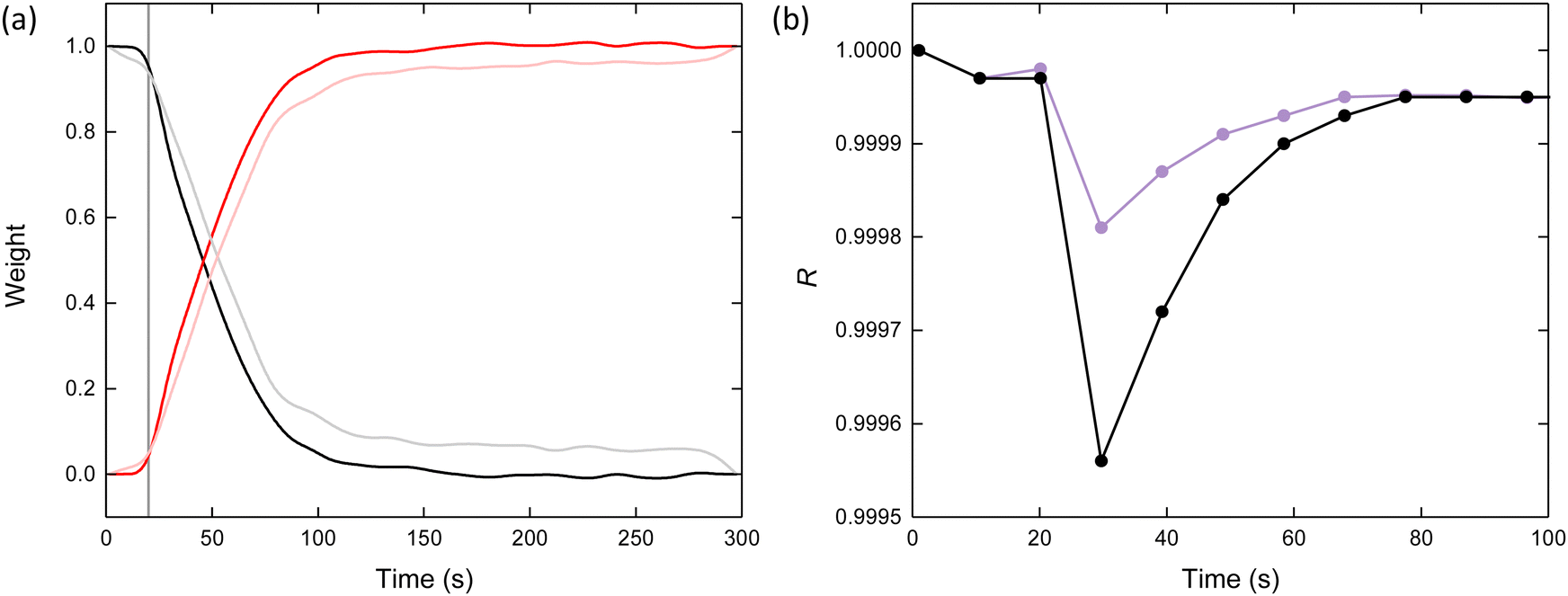 | ||
| Fig. 4 (a) Comparison between the weightings obtained for iron(III) nitrate and Fe-BTC obtained through linear combination analysis in the XANES (black and red) and EXAFS (grey and pink), respectively. The vertical line marks when the reagents were combined at t = 20 s. (b) Comparison of the R-values obtained for the LCA using two (reagent and product – black) and three (reagent, product and intermediate – purple) spectra in the XANES region. | ||
In this analysis we have only accounted for two of the three anticipated Fe species (reactant and product) described in our mechanism, neglecting the intermediate. Hence, it was anticipated that this analysis would exhibit a reduced quality of fit in the intermediary regime of the series. Indeed, the R-value (a measure of the goodness-of-fit) displayed a clear decrease between t = 20 and 30 s, with the R-value at t = 30 s possessing the lowest of those observed (i.e., 10 s after linker addition) [Fig. 4b]. Together, this points towards the importance of an intermediate in understanding the mechanism of Fe-BTC formation.
Due to the air-sensitive nature of the intermediate, which is rapidly oxidised in air, it was not possible to measure an experimental spectrum for Fe(II)-BTC.37 Instead, the XANES region for Fe(II)-BTC was calculated from the structure reported in Ref. 37 using a DFT approach.47 LCA performed using iron(III) nitrate, Fe(II)-BTC and Fe-BTC produced an appreciably better fit according to the obtained R-values, though still not in perfect agreement with the experimental data [Fig. S14, ESI†]. From this analysis, the weighting of Fe(II)-BTC was maximal at t = 30 s, with a value of 0.05. Synthesising and measuring experimental standards for all of the potential intermediates is no practical task and hence conventional analysis aimed at uncovering the exact speciation was not a feasible challenge. Furthermore, it is important to note that the additional parametrisation in using a third component is almost guaranteed to result in an improved fit. Given this ambiguity, we turned to multivariate analysis as an unbiased method to study the kinetics of Fe-BTC formation.
Principal component analysis (PCA), a dimensionality reduction technique, was used to investigate the role of the intermediate on the reaction kinetics. PCA decomposes a dataset into linear combinations of orthogonal components that best capture the variance in the data.41 Given the magnitude of the variations within the spectra is significantly smaller than the magnitude of the spectra themselves, the first principal component (PC1) can be thought of as an average of the data and hence resembles the shape of a typical spectrum [Fig. S15, ESI†]. Subsequent components (PC2, PC3, etc.) represent, in effect, distortions in the average spectrum and do not themselves look like spectra [Fig. S16, ESI†]. Beyond PC1, principal components 2 to 5 account for 84.9, 3.5, 1.8, and 0.3% of the remaining variance, respectively. Through visual inspection of the components, their Fourier transforms and their corresponding eigenvalues, it was clear that PC5 was dominated by noise and could therefore be disregarded from subsequent analysis. Hence, we obtain three statistically significant components (PC2 to 4), which describe the variability of the data. As noted, these principal components describe distortions in the average spectrum and hence are not easily interpreted in terms of measured XAS spectra. Their weightings, on the other hand, provide insight into how the distortions vary as a function of time [Fig. S16, ESI†]. In general, the weightings of the three components exhibit negligible change at t < 20 s. Upon mixing of the reagents at t = 20 s, all three components show immediate variation with time: PC2 decreases, PC3 increases to a maximum at t = 73 s before decreasing, and PC4 increases. Based on the variation of these weightings, we may tentatively ascribe PC2, PC3 and PC4 to the reactant, intermediate and product, respectively, given their variation is in line with that anticipated from our simple model.
The weightings of the three components (PC2, PC3 and PC4) can be transformed into three separate reaction coordinates, α, analogous to the extent of crystallisation parameter used in crystalline systems [Fig. 5].48 These represent the consumption of the reagent (PC2 becomes αreagent), transient formation of the intermediate (PC3 becomes αintermediate), and formation of the product (PC4 becomes αproduct). Upon inspection of these reaction coordinates, it becomes apparent how their variation correlates to the concentration profiles hypothesised earlier. To understand the kinetics at play, these reaction coordinates were analysed using the Avrami–Erofeev,49,50 Gualtieri51 and Sharp–Hancock models [see Methods in ESI†].52
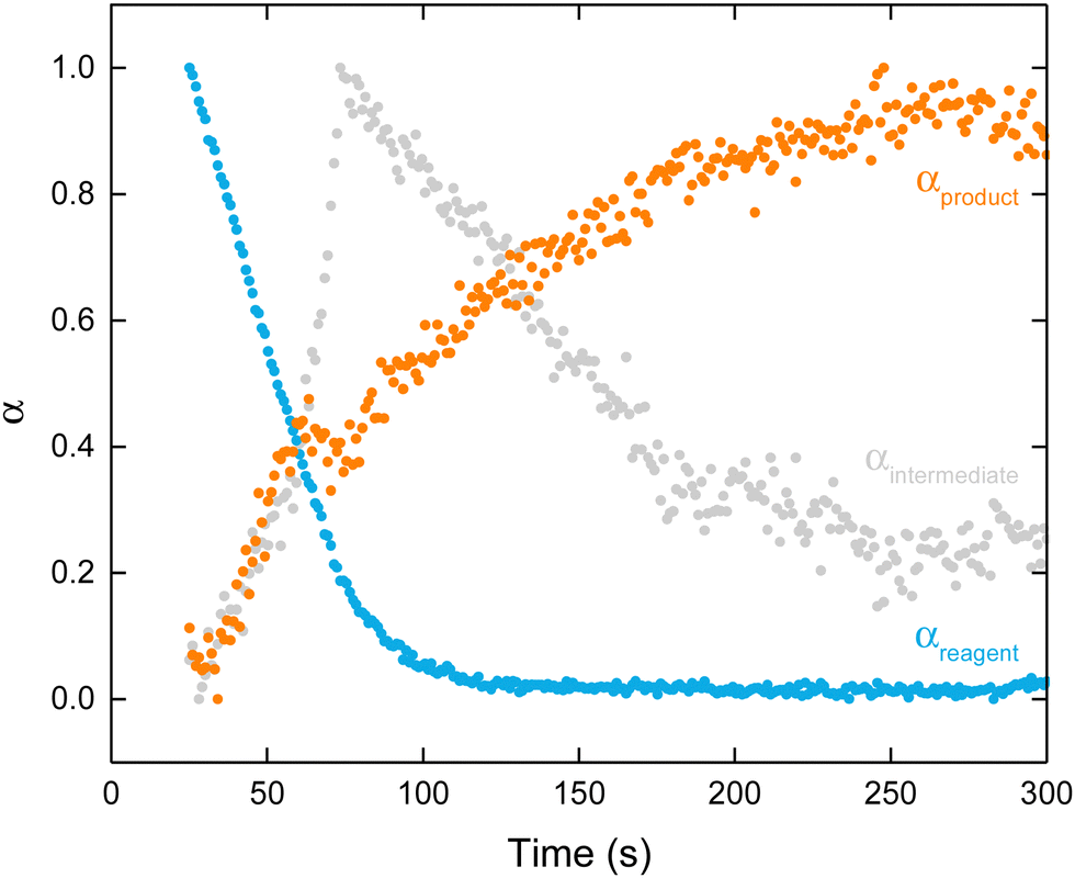 | ||
| Fig. 5 Variation in α as a function of time for the reagent (blue), intermediate (grey), and product (orange) obtained via transformation of their respective weightings. | ||
The Avrami–Erofeev relation, where k is the rate constant of growth and n is the Avrami constant, was originally derived for solid-state reactions but has since been applied to many solution-based reactions.49 The Avrami constant contains information regarding the mechanism of growth. From a non-linear least-square global fit to αproduct, = 0.010(2) s−1 and n = 1.00k(3) suggesting the overall mechanism is phase-boundary mediated and not diffusion-mediated [Fig. 6a]. This may be reflective of the nanocomposite nature of Fe-BTC, wherein nanocrystalline domains are embedded within an amorphous matrix, though further investigations would be required to confirm this. While the Avrami model provides a good foundation, its simplicity fails to account for the inflection point around t = 63 s in αproduct.
 | ||
| Fig. 6 Kinetic analysis of αproduct using the (a) Avrami–Erofeev and (b) Gualtieri model. (c) Sharp–Hancock plots of αproduct fitted using two linear regression models. (d) Comparison between (left axis) αintermediate (grey) and (right axis) the probability distribution function for nucleation, PN, determined from the Gualtieri model (purple). | ||
The Gualtieri model, where nucleation and growth are treated independently, was derived for solution-based reactions.51 Not only does this additional parameterisation provide a noticeably better fit to the feature around t = 63 s, but it also begins to uncover the relationship between Fe-BTC and the intermediate [Fig. 6b]. The rate constants for nucleation (kN) and growth (kG) were 0.016(3) and 0.055(2) s−1, respectively, with growth occurring over three times faster than nucleation. The exponent nG was 2.3(3) which indicates multidimensional growth is occurring. The rate constant obtained from the Avrami model and kN are very similar, suggesting that the overall rate of Fe-BTC formation is likely limited by nucleation. It is important to consider what nucleation entails for the formation of an amorphous system. We can describe nucleation of Fe-BTC as an umbrella term for the reduction, Fe(II)-BTC formation and oxidation steps that precede Fe-BTC formation.
Due to the presence of an intermediate, the formation of Fe-BTC is unlikely to occur via a simple linear mechanism. To assess the temporal nature of the mechanism, Sharp–Hancock modelling followed by linear regression analysis was performed to identify mechanistic changes. The Sharp–Hancock plot, fitted using a single straight line, resulted in k (0.011(3) s−1) and n (0.97(1)) values consistent with the non-linear least-square global Avrami–Erofeev analysis itself [Fig. S17, ESI†]. However, it was clear that two distinct linear regions were present in the Sharp–Hancock plot, indicating a mechanistic change was occurring. Piecewise linear regression of the two regions indicated that one mechanism dominates at t < 63 s, while another operates at t > 73 s, with a short cross-over period occurring in between [Fig. 6c]. The associated rate constant changed from 0.020(4) s−1 to 0.010(2) s−1 and the Avrami exponent from 1.6(1) to 1.03(2), in the first and second stages, respectively. Kinetically, this indicates the rate of Fe-BTC formation decreases with time, with the rate in the second regime approaching that obtained from the global Avrami fit. This will, in part, be due to the consumption of the reagents within the system. Mechanistically, this suggests that the formation of Fe-BTC first takes place somewhere in between the phase-boundary and nucleation-limited regimes – as suggested by kN in the Gualtieri analysis – and then switches to a phase-boundary limited process later on. Together, this points toward a complex mechanism of formation.
To understand this change in the rate-limiting step, we examined the Gaussian probability distribution function of nucleation (PN) [Fig. 6d]. As described by aN and bN obtained from the Gualtieri model, PN was very broad with a non-zero probability of nucleation occurring directly after mixing. Coupled with the value of kN, this suggests that slow and continuous nucleation occurs throughout Fe-BTC formation. The distribution of PN was centred around t = 88 s, where the probability of nucleation is maximal.
The formation of the intermediate and nucleation of Fe-BTC are intimately connected and this is reflected in the concurrent rise and fall of Fe(II)-BTC formation (αintermediate) and PN [Fig. 6d]. From the position of their maxima (t = 73 s for αintermediate and t = 88 s for PN), we can infer there may be a delay between Fe(II)-BTC formation and nucleation of Fe-BTC – this is likely associated with oxidation that occurs. The positions of these maxima are also concurrent with the consumption of iron(III) nitrate, with αreactant reaching 0.1 at 83 s. Hence, we deduce that in the first half of the mechanism, the low probability of Fe-BTC nucleation occurs due to the limited formation of Fe(II)-BTC that has occurred leading to a partially nucleation-mediated rate-limiting step.
In summary, our analysis suggests [Table S1, ESI†]:
• The overall formation of Fe-BTC is characterised by a phase boundary-mediated mechanism.
• The rate of Fe-BTC growth is over three times faster than nucleation.
• The role of nucleation decreases as the reaction progresses, with the mechanistic change towards a predominantly phase-boundary mediated between t = 63 and 73 s.
• The overall rate of Fe-BTC formation halves when this mechanistic change occurs.
• The probability distribution for nucleation of Fe-BTC is very broad and is maximal at t = 88 s.
• The relationship between the formation of Fe(II)-BTC and the nucleation of Fe-BTC emerges when αintermediate and PN are compared.
We now turn to a possible mechanistic interpretation of our quantitative results. The dynamic nature of Fe-BTC formation, in particular the abrupt mechanistic change, can be rationalised by considering the dominant Fe species in solution as the reaction progresses; a similar framework has been proposed for the formation of ZIF-8.53 At the start of the reaction, the hydroxy-aqua Fe ion will be present in the solution and, as the reaction progresses, the Fe speciation becomes increasingly dominated by carboxylate-coordinated species due to electrostatic attraction between the metal cations and anionic deprotonated linker [Fig. 7a and b]. To nucleate Fe-BTC, the Fe(II)-BTC intermediate must be generated, requiring a specific Fe coordination environment to be obtained. Therefore, the temporal speciation of Fe in the solution is a key governing factor in the kinetics of Fe-BTC formation.
 | ||
| Fig. 7 Proposed schematic mechanism for Fe-BTC formation. (a) Shows the direction in which the equilibria shift with time, (b) simplified pre-equilibrium that is established in solution where x + y + 2z = 6 from the octahedral coordination geometry (φ1 denotes the carboxylate group of the 1,3,5-benzentricarboxylate ion bonding in bridging mode between two Fe centres and φ2 denotes a chelate mode about a single Fe centre) (c) transformation to the average local structure of Fe(II)-BTC, (d) average local structure of the Fe(II)-BTC intermediate, (e) oxidation of the intermediate, (f) average local structure of Fe-BTC, and (g) continued growth to form Fe-BTC. Insets show the Fe environments in Fe(II)-BTC (left) and Fe-BTC (right). FeO6 octahedra (grey), O (red) and C (grey). | ||
At the start of the reaction, the Fe coordination sphere is dominated by water (x > 4, i.e., undercoordinated by carboxylate groups with respect to Fe(II)-BTC). Formation of Fe(II)-BTC occurs by rapid coordination of carboxylate groups before oxidation and Fe-BTC nucleation can occur [Fig. 7c]. As the reaction progresses, an increasing proportion of the Fe speciation becomes dominated by the x = 4 cluster required to generate Fe(II)-BTC. Hence, nucleation of Fe-BTC can occur rapidly. Towards the end of the reaction, the speciation of Fe becomes increasingly dominated by carboxylate groups (x < 4, i.e., over-coordinated by carboxylate groups with respect to Fe(II)-BTC). Formation of Fe(II)-BTC occurs by slow de-coordination of carboxylate groups before Fe-BTC nucleation can occur [Fig. 7c]. This is coupled with the depletion of the reagents which further slows the overall rate of reaction. Between t = 63 and 73 s, the switchover from the dominant Fe species being undercoordinated to being over-coordinated, with respect to the Fe(II)-BTC coordination sphere, occurs. Once the Fe(II)-BTC intermediate has formed, oxidation occurs and Fe-BTC can be nucleated [Fig. 7d to f]. Towards the end of the reaction, it is the largely continued growth of Fe-BTC that will occur causing structural changes on larger length scales (i.e., aggregation and macroscopic assembly) [Fig. 7g].
Conclusion
In summary, we have performed an in situ study on the formation of the amorphous Fe-BTC framework using synchrotron X-ray absorption spectroscopy. We detected the presence of a transient intermediate and showed that the rate and mechanism of Fe-BTC formation exhibit an abrupt change partway through the reaction. Finally, we proposed a simple model, based on the temporal speciation of Fe, that helps rationalise the observed mechanistic changes. Overall, our analysis indicates that Fe-BTC formation is characterised by slow, continuous nucleation and simultaneous, fast growth. The nucleation step is complex and is highly correlated with the formation of the transient intermediate.This study contributes to a growing body of work on the formation of MOFs. However, our focus on the formation of an amorphous MOF is a particularly unique contribution to this area of research. To fully understand the atomic assembly of these systems, a combination of spectroscopy, scattering and microscopy techniques will be required. Using this knowledge, we can directly and systematically influence the framework's structure to target improved functionality. Fe-BTC is a particularly interesting system to study in this regard, as it exhibits structural transformations across several orders of magnitude. Three key areas for future work are (i) the assembly of the hierarchical local structure on a longer length scale, (ii) the mechanism of redox and (iii) the macroscale aggregation of the gel. We anticipate that each of these domains will afford further interesting results.
This emerging area of study is primed for the development of new theories governing the foundational principles behind amorphous MOF synthesis, rather than simply adapting those devised for crystalline systems. Routes towards these new theories may perhaps be achieved by drawing on concepts from other fields, such as metal–organic polyhedra,54 polyoxometalates55 and organic polymers,56 but first require us to overcome the scarcity of experimental data by performing studies such as the work presented here. These studies will reveal the potential generality of the mechanism we have presented towards other systems. A fundamental understanding of the formation of amorphous MOFs is key to developing these materials for use in catalysis, biomedicine and gas sorption. These studies also have clear implications for our understanding of crystalline MOFs, of which many have been found to form via the generation of amorphous intermediates phases. Ultimately, in situ studies probing atomic structure, mechanism and kinetics will enable us to wield disorder as a powerful means to design next-generation functional materials.
Author contributions
AFS conceptualised the project and designed the experiments. AFS and MFT collected UV-vis data. AFS, MFT, CCB, and LK collected synchrotron X-ray absorption spectroscopy data. AFS processed and analysed the data with the help of MFT and LK. AFS wrote the manuscript and all authors contributed to the final draft. TDB and TJ acquired funding.Conflicts of interest
TJ works for a company with interests in the commercialisation of MOF materials (Johnson Matthey PLC) and the remaining authors declare no competing interests.Acknowledgements
AFS acknowledges the EPSRC for a PhD studentship award under the industrial CASE scheme, along with Johnson Matthew PLC (JM11106). MFT acknowledges Corning Incorporated for a PhD studentship. TDB thanks the Royal Society for both a University Research Fellowship (URF\R\211013) and a research grant (RGS\R2\212221). TDB and CCB acknowledge funding from a Leverhulme Trust Research Project Grant (RPG-2020-005). We would thank Diamond Light Source for the provision of beam time at the I20-EDE beamline (Experiment Number SP28536-1). AFS would also like to thank Dr Hamish Yeung (University of Birmingham) for useful discussions regarding nucleation and MOF formation.References
- T. D. Bennett and A. K. Cheetham, Acc. Chem. Res., 2014, 47, 1555–1562 CrossRef CAS PubMed.
- T. D. Bennett and S. Horike, Nat. Rev. Mater., 2018, 3, 431–440 CrossRef.
- A. Sapnik, I. Bechis, A. Bumstead, T. Johnson, P. Chater, D. Keen, K. Jelfs and T. Bennett, Nat. Commun., 2022, 13, 2173 CrossRef CAS PubMed.
- M. J. Van Vleet, T. Weng, X. Li and J. R. Schmidt, Chem. Rev., 2018, 118, 3681–3721 CrossRef CAS PubMed.
- M. Filez, C. Caratelli, M. Rivera-Torrente, F. Muniz-Miranda, M. Hoek, M. Altelaar, A. J. R. Heck, V. Van Speybroeck and B. M. Weckhuysen, Cell Rep. Phys. Sci., 2021, 2, 100680 CrossRef CAS.
- S. Surblé, F. Millange, C. Serre, G. Férey and R. I. Walton, Chem. Commun., 2006, 1518–1520 RSC.
- J. Li and F. L. Deepak, Chem. Rev., 2022, 122, 16911–16982 CrossRef CAS PubMed.
- B. Jin, Z. Liu and R. Tang, CrystEngComm, 2020, 22, 4057–4073 RSC.
- A. Dhakshinamoorthy, M. Alvaro, P. Horcajada, E. Gibson, M. Vishnuvarthan, A. Vimont, J.-M. Grenèche, C. Serre, M. Daturi and H. Garcia, ACS Catal., 2012, 2, 2060–2065 CrossRef CAS.
- A. F. Sapnik, C. W. Ashling, L. K. Macreadie, S. J. Lee, T. Johnson, S. G. Telfer and T. D. Bennett, J. Mater. Chem. A, 2021, 9, 27019–27027 RSC.
- A. F. Sapnik, I. Bechis, S. M. Collins, D. N. Johnstone, G. Divitini, A. J. Smith, P. A. Chater, M. A. Addicoat, T. Johnson, D. A. Keen, K. E. Jelfs and T. D. Bennett, Nat. Commun., 2021, 12, 2062 CrossRef CAS PubMed.
- L. Sciortino, A. Alessi, F. Messina, G. Buscarino and F. M. Gelardi, J. Phys. Chem. C, 2015, 119, 7826–7830 CrossRef CAS.
- M. Rivera-Torrente, M. Filez, R. Hardian, E. Reynolds, B. Seoane, M.-V. Coulet, F. E. Oropeza Palacio, J. P. Hofmann, R. A. Fischer, A. L. Goodwin, P. L. Llewellyn and B. M. Weckhuysen, Chem. – Eur. J., 2018, 24, 7498–7506 CrossRef CAS PubMed.
- I. Bechis, A. F. Sapnik, A. Tarzia, E. H. Wolpert, M. A. Addicoat, D. A. Keen, T. D. Bennett and K. E. Jelfs, Chem. Mater., 2022, 34, 9042–9054 CrossRef CAS PubMed.
- A. Sapnik, C. Sun, J. Laulainen, D. Johnstone, R. Brydson, T. Johnson, P. Midgley, T. Bennett and S. Collins, Commun. Chem., 2023, 6, 92 CrossRef CAS PubMed.
- M. R. Lohe, M. Rose and S. Kaskel, Chem. Commun., 2009, 6056–6058 RSC.
- M. Sanchez-Sanchez, I. de Asua, D. Ruano and K. Diaz, Cryst. Growth Des., 2015, 15, 4498–4506 CrossRef CAS.
- J. Hou, A. F. Sapnik and T. D. Bennett, Chem. Sci., 2020, 11, 310–323 RSC.
- P. Horcajada, S. Surblé, C. Serre, D.-Y. Hong, Y.-K. Seo, J.-S. Chang, J.-M. Grenèche, I. Margiolaki and G. Férey, Chem. Commun., 2007, 2820–2822 RSC.
- G. Zhong, D. Liu and J. Zhang, Cryst. Growth Des., 2018, 18, 7730–7744 CrossRef CAS.
- C. R. Quijia, C. Lima, C. Silva, R. C. Alves, R. Frem and M. Chorilli, J. Drug Delivery Sci. Technol., 2021, 61, 102217 CrossRef CAS.
- Y. Fang, Z. Yang, H. Li and X. Liu, Environ. Sci. Pollut. Res., 2020, 27, 4703–4724 CrossRef CAS PubMed.
- Y. Luo, B. Tan, X. Liang, S. Wang, X. Gao, Z. Zhang and Y. Fang, Ind. Eng. Chem. Res., 2019, 58, 7801–7807 CrossRef CAS.
- J. Castells-Gil, N. M. Padial, N. Almora-Barrios, I. da Silva, D. Mateo, J. Albero, H. García and C. Martí-Gastaldo, Chem. Sci., 2019, 10, 4313–4321 RSC.
- H. Reinsch and N. Stock, CrystEngComm, 2012, 15, 544–550 RSC.
- F. Zhang, X. Zou, W. Feng, X. Zhao, X. Jing, F. Sun, H. Ren and G. Zhu, J. Mater. Chem., 2012, 22, 25019–25026 RSC.
- X. Meng, R. Luo, G. Guo, Y. Li, H. Fang, P. Bai, J. Lyu and X. Guo, Desalination, 2022, 541, 116038 CrossRef CAS.
- M. Haouas, C. Volkringer, T. Loiseau, G. Férey and F. Taulelle, Chem. Mater., 2012, 24, 2462–2471 CrossRef CAS.
- T. Steenhaut, Y. Filinchuk and S. Hermans, J. Mater. Chem. A, 2021, 9, 21483–21509 RSC.
- K. Guesh, C. A. D. Caiuby, Á. Mayoral, M. Díaz-García, I. Díaz and M. Sanchez-Sanchez, Cryst. Growth Des., 2017, 17, 1806–1813 CrossRef CAS.
- L. Han, H. Qi, D. Zhang, G. Ye, W. Zhou, C. Hou, W. Xu and Y. Sun, New J. Chem., 2017, 41, 13504–13509 RSC.
- F. Zhang, J. Shi, Y. Jin, Y. Fu, Y. Zhong and W. Zhu, Chem. Eng. J., 2015, 259, 183–190 CrossRef CAS.
- Y.-K. Seo, J. W. Yoon, J. S. Lee, U.-H. Lee, Y. K. Hwang, C.-H. Jun, P. Horcajada, C. Serre and J.-S. Chang, Microporous Mesoporous Mater., 2012, 157, 137–145 CrossRef CAS.
- J. Shi, S. Hei, H. Liu, Y. Fu, F. Zhang, Y. Zhong and W. Zhu, J. Chem., 2013, e792827 Search PubMed.
- F. Jeremias, S. K. Henninger and C. Janiak, Dalton Trans., 2016, 45, 8637–8644 RSC.
- T. Birsa Čelič, M. Rangus, K. Lázár, V. Kaučič and N. Zabukovec Logar, Angew. Chem., 2012, 51, 12490–12494 CrossRef PubMed.
- T. Steenhaut, S. Hermans and Y. Filinchuk, New J. Chem., 2020, 44, 3847–3855 RSC.
- T. J. Bastow and A. Trinchi, Solid State Nucl. Magn. Reson., 2009, 35, 25–31 CrossRef CAS PubMed.
- Y.-H. P. Hsieh and Y. P. Hsieh, J. Agric. Food Chem., 2000, 48, 1569–1573 CrossRef CAS PubMed.
- S. Diaz-Moreno, M. Amboage, M. Basham, R. Boada, N. E. Bricknell, G. Cibin, T. M. Cobb, J. Filik, A. Freeman, K. Geraki, D. Gianolio, S. Hayama, K. Ignatyev, L. Keenan, I. Mikulska, J. F. W. Mosselmans, J. J. Mudd and S. A. Parry, J. Synchrotron Radiat., 2018, 25, 998–1009 CrossRef PubMed.
- S. Calvin, XAFS for Everyone, CRC Press, Boca Raton, 2013 Search PubMed.
- M. Basham, J. Filik, M. T. Wharmby, P. C. Y. Chang, B. El Kassaby, M. Gerring, J. Aishima, K. Levik, B. C. A. Pulford, I. Sikharulidze, D. Sneddon, M. Webber, S. S. Dhesi, F. Maccherozzi, O. Svensson, S. Brockhauser, G. Náray and A. W. Ashton, J. Synchrotron Radiat., 2015, 22, 853–858 CrossRef PubMed.
- S. DeBeer George, T. Petrenko and F. Neese, J. Phys. Chem. A, 2008, 112, 12936–12943 CrossRef CAS PubMed.
- J. Shin, M. Kim, J. Cirera, S. Chen, G. J. Halder, T. A. Yersak, F. Paesani, S. M. Cohen and Y. S. Meng, J. Mater. Chem. A, 2015, 3, 4738–4744 RSC.
- B. Ravel and M. Newville, J. Synchrotron Radiat., 2005, 12, 537–541 CrossRef CAS PubMed.
- C. Castillo-Blas, I. Romero-Muñiz, A. Mavrandonakis, L. Simonelli and A. E. Platero-Prats, Chem. Commun., 2020, 56, 15615–15618 RSC.
- O. Bunău and Y. Joly, J. Phys.: Condens. Matter, 2009, 21, 345501 CrossRef PubMed.
- P. Guccione, L. Palin, B. D. Belviso, M. Milanesio and R. Caliandro, Phys. Chem. Chem. Phys., 2018, 20, 19560–19571 RSC.
- M. Avrami, J. Chem. Phys., 1939, 7, 1103–1112 CrossRef CAS.
- Y. P. Khanna and T. J. Taylor, Polym. Eng. Sci., 1988, 28, 1042–1045 CrossRef CAS.
- A. F. Gualtieri, Phys. Chem. Min., 2001, 28, 719–728 CrossRef CAS.
- J. D. Hancock and J. H. Sharp, J. Am. Ceram. Soc., 1972, 55, 74–77 CrossRef CAS.
- H. H.-M. Yeung, A. F. Sapnik, F. Massingberd-Mundy, M. W. Gaultois, Y. Wu, D. A. X. Fraser, S. Henke, R. Pallach, N. Heidenreich, O. V. Magdysyuk, N. T. Vo and A. L. Goodwin, Angew. Chem., 2019, 58, 566–571 CrossRef CAS PubMed.
- A. Legrand, G. A. Craig, M. Bonneau, S. Minami, K. Urayama and S. Furukawa, Chem. Sci., 2019, 10, 10833–10842 RSC.
- A. S. Anker, T. L. Christiansen, M. Weber, M. Schmiele, E. Brok, E. T. S. Kjær, P. Juhás, R. Thomas, M. Mehring and K. M. Ø. Jensen, Angew. Chem., 2021, 60, 20407–20416 CrossRef CAS PubMed.
- R. Dawson, A. I. Cooper and D. J. Adams, Prog. Polym. Sci., 2012, 37, 530–563 CrossRef CAS.
Footnote |
| † Electronic supplementary information (ESI) available. See DOI: https://doi.org/10.1039/d3sm01658g |
| This journal is © The Royal Society of Chemistry 2024 |