 Open Access Article
Creative Commons Attribution 3.0 Unported Licence
Controlled mechanical properties of poly(ionic liquid)-based hydrophobic ion gels by the introduction of alumina nanoparticles with different shapes†
Yuna
Mizutani
 a,
Takaichi
Watanabe
 *a,
Carlos G.
Lopez
 b and
Tsutomu
Ono
 a
a
aDepartment of Applied Chemistry, Graduate School of Natural Science, Okayama University, 3-1-1, Tsushima-naka, Kita-ku, Okayama, 700-8530, Japan. E-mail: wata-t@okayama-u.ac.jp; Tel: +81-86-251-8072
bDepartment of Materials Science and Engineering, The Pennsylvania State University, University Park, Pennsylvania 16802, USA
First published on 18th January 2024
Abstract
Ionic–liquid gels, also known as ion gels, have gained considerable attention due to their high ionic conductivity and CO2 absorption capacity. However, their low mechanical strength has hindered their practical applications. A potential solution to this challenge is the incorporation of particles, such as silica nanoparticles, TiO2 nanoparticles, and metal–organic frameworks (MOFs) into ion gels. Comparative studies on the effect of particles with different shapes are still in progress. This study investigated the effect of the shape of particles introduced into ion gels on their mechanical properties. Consequently, alumina/poly(ionic liquid) (PIL) double-network (DN) ion gels consisting of clustered alumina nanoparticles with various shapes (either spherical or rod-shaped) and a chemically crosslinked poly[1-ethyl-3-vinylimidazolium bis(trifluoromethanesulfonyl)imide] (PC2im-TFSI, PIL) network were prepared. The results revealed that the mechanical strengths of the alumina/PIL DN ion gels were superior to those of PIL single-network ion gels without particles. Notably, the fracture energies of the rod-shaped alumina/PIL DN ion gels were approximately 2.6 times higher than those of the spherical alumina/PIL DN ion gels. Cyclic tensile tests were performed, and the results indicate that the loading energy on the ion gel was dissipated through the fracture of the alumina network. TEM observation suggests that the variation in the mechanical strength depending on the shape can be attributed to differences in the aggregation structure of the alumina particles, thus indicating the possibility of tuning the mechanical strength of ion gels by altering not only particle kinds but its shape.
Introduction
Ion gels are soft materials consisting of crosslinked polymer networks and a large amount of ionic liquid (IL). The IL imparts the ion gels with its intrinsic advantages (i.e. negligible vapour pressure, high thermal stability,1 flame resistance,2 high ionic conductivity,3,4 and selective CO2 absorption capacity5–7), while the polymer matrix enables their processability. Furthermore, the physicochemical properties of ion gels can be tailored by selecting appropriate combinations of cations and anions in the ILs.8,9 Ion gels can be thus used in various applications, including strain sensors,10 actuators,11,12 supercapacitors,13–15 energy storage devices, and CO2 separation membranes.7 Moreover, employing hydrophobic polymer networks and hydrophobic ILs in ion gels has provided these gels with excellent durability under high humidity and underwater conditions,16,17 and thus expanded their applications as separation membranes and soft electronic devices in high humidity or aquatic environments.Like other polymer gel systems, ion gels suffer from limited mechanical stability, which limits their practical applications.18 Significant efforts have therefore been made to develop strategies to improve the mechanical properties of ion gels. Several strategies have been proposed to enhance the mechanical strength of ion gels, such as the introduction of homogeneous crosslinked polymer networks,19–21 self-assembled ABA-type triblock copolymers,11,22 physical gelation systems using the entanglement of ultra-high molecular weight polymers,9,23 crystallisable polymer networks,24,25 and double network (DN) concepts between the polymers26 or between nanomaterials (fillers) and the polymer.27 In particular, nanomaterial/polymer composite DN ion gels have been gaining considerable attention because toughening of the ion gels is achieved by simply adding the nanomaterials to their precursor solution. Consequently, this approach can be applied to various monomer systems.
DN ion gels comprise two interpenetrating networks: a brittle, rigid partially clustered nanomaterial network and a soft and stretchable crosslinked polymer network. The toughening mechanism is based on energy dissipation.27 The nanomaterial network is preferentially destroyed upon applying a large strain to the gels, which dissipates the loading energy, during which the stretchable polymer network maintains the integrity of the gel. Several studies have reported the preparation of hydrophobic DN ion gels by the introduction of various nanomaterial networks, including silica nanoparticles (NPs)28–30 and TEMPO-oxidised cellulose nanofibres.31 The results of these studies revealed that the presence of hydroxyl groups on the surface of the nanomaterials is essential for the formation of nanoparticle networks in ILs and realising the toughening of ion gels. However, the relationship between the shape of nanoparticles of the brittle network and the macroscopic mechanical properties of the gels has not yet been investigated.
This paper reports the development of alumina/poly(ionic liquid) (PIL) DN ion gels composed of clustered alumina NPs with different shapes (spherical or rod-shaped) and chemically crosslinked poly[1-ethyl-3-vinylimidazolium bis(trifluoromethanesulfonyl)imide] (PC2im-TFSI, PIL) networks (Scheme 1). The effects of the shape of the alumina NPs and their secondary network structure on the mechanical properties of the gels were also investigated. Since alumina is a well-known filler that imparts polymer composites with high heat resistance32 and strength33 and is expected to physically interact with IL owing to its hydroxyl groups on the surface, the rheological behaviour of the alumina (spherical or rod-shaped)/IL/ethyl acetate (EA) dispersion was investigated to confirm the formation of a physically crosslinked alumina network in the IL. Subsequently, alumina/PIL DN ion gels with varying amounts/shapes of alumina in addition to PIL single-network (SN) ion gels were prepared, and their physicochemical properties (mechanical properties, glass transition temperatures (Tg), and ionic conductivities) were compared. The ion gels were also subjected to cyclic tensile tests to evaluate their degrees of energy dissipation. The brittle network structures formed by the alumina NPs with different shapes in the IL were assessed using transmission electron microscopy (TEM). Finally, the effects of the filler shape on the mechanical properties of ion gels were evaluated.
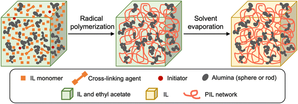 | ||
| Scheme 1 Schematic illustration of the alumina/PIL DN ion gels prepared via a photo-induced radical polymerisation and subsequent solvent evaporation. | ||
Results and discussion
To evaluate the interparticle interactions of alumina NPs in 1-butyl-3-methylimidazolium bis(trifluoromethanesulfonyl)imide ([C4mim][TFSI]), the shear-rate dependencies on the viscosities of the [C4mim][TFSI] solutions containing alumina of varying concentrations and shapes (spherical or rod-shaped) was investigated using a rheometer. Fig. 1 illustrates the variation in viscosity as a function of the shear rate for dispersions of spherical- and rod-shaped alumina/[C4mim][TFSI]/EA at different alumina concentrations, compared with an IL/EA mixture without alumina. The results revealed that the viscosity of the IL/EA mixture was independent of the shear rate. This Newtonian behaviour is characteristic of non-structured fluids. Conversely, the alumina/[C4mim][TFSI]/EA dispersions demonstrated shear thinning irrespective of the alumina shape, where the viscosity decreased with an increase in shear rate. This can be attributed to the disruption of physical bonds between the alumina NPs under shear, which is analogous to the previously reported behaviour of silica nanoparticle dispersions in IL.34,35 For well-dispersed particles, the Einstein viscosity equation expects the zero-shear rate viscosity to increase by only ≈2% for the 0.85 vol% sample. The large apparent viscosities of the solutions with alumina NPs at low shear rates and their strong non-Newtonian character contrast with those of well-dispersed colloids,36 and give evidence of the formation of large scale structures. This presumably occurs because the particles aggregate into clusters rather than being individually dispersed in the solution. The spherical alumina dispersions exhibited higher low-shear viscosities than those of the rod-shaped dispersions, which is assigned to the larger specific surface area of the spheres, enabling the formation of a three-dimensional dendritic structure. The viscosity curves of the spherical alumina dispersions were steeper than those of the rod-shaped dispersions, thus implying that shear forces disrupted the spherical alumina aggregates more readily. Shear thickening was also observed in the alumina/[C4mim][TFSI]/EA dispersions regardless of the shape of alumina. The threshold shear rate at which the viscosity started to increase was in the range of 100–101 s−1 for spherical shapes and between 10−1–100 s−1 for rod shapes, thus indicating that shear forces induced a pseudo-cluster formation in rod-shaped alumina because of its higher aspect ratio which is more likely to form these clusters. As the alumina concentration increased, the threshold shear rate decreased, thus implying a reduced possibility of shear-induced structural breakdown of alumina with increased alumina concentrations. Then, oscillatory shear viscoelasticity measurements were conducted to determine whether alumina could induce gelation in [C4mim][TFSI], as shown in Fig. 2. At an alumina volume fraction of 2.1 vol% in [C4mim][TFSI]/EA dispersions, the elastic modulus (G′) was found to be approximately independent of frequency and larger than the viscous modulus (G′′) for both spherical alumina and rod-shaped alumina throughout the measured frequency range. These findings suggest that both types of alumina dispersions are capable of forming physical gels in [C4mim][TFSI], thereby acting as the network in DN ion gels (Scheme S2, ESI†). Additionally, the interparticle interaction potentials of the alumina/[C4mim][TFSI]/EA dispersions were quantified by analysing the variations in the plateau storage modulus, , as a function of the NPs volume fraction.36,37 Fig. S3 illustrates that the slope of
  with respect to the volume fraction of alumina was consistent for both spherical and rod-shaped alumina. This result suggests that the shape of alumina NPs could not influence the magnitude of interparticle interactions (ESI†).
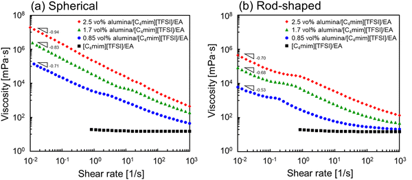 | ||
| Fig. 1 Shear rate dependencies on the viscosities of (a) spherical and (b) rod-shaped alumina/[C4mim][TFSI]/EA dispersions with different alumina concentrations. | ||
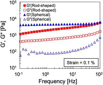 | ||
| Fig. 2 Oscillatory shear frequency-sweep viscoelasticity of spherical and rod-shaped alumina/[C4mim][TFSI]/EA dispersions at a 2.1 vol% alumina concentration. | ||
Alumina/PIL DN ion gels with varying alumina concentration/shapes, in addition to PIL SN ion gels were prepared. The PIL DN ion gels, consisting of alumina NPs and cross-linked PC2im-TFSI, were prepared via the photo-induced radical polymerization of 1-ethyl-3-vinylimidazolium bis(trifluoromethanesulfonyl)imide ([C2vim][TFSI]) in a mixture containing alumina, [C4mim][TFSI] (as IL), 1,4-bis(3-vinylimidazolium-1-yl) butane bis(trifluoromethanesulfonyl)imide ([(Vim)2C4][TFSI]2, as IL cross-linker), IRGACURE® 2959 (as the photoinitiator), and EA (as the solvent). EA was then removed by solvent evaporation. PIL SN ion gels were prepared using a similar method but without the addition of alumina.
Fig. 3 displays the photographs of the prepared ion gels. The PIL SN ion gel was found to be highly transparent with a light orange colour (Fig. 3a), while the alumina/PIL DN ion gels were translucent white (Fig. 3b and c). The incorporation of alumina resulted in a cloudy appearance of the ion gel, thus indicating that alumina NPs tended to form microscale aggregates within the ion gels. The rod-shaped alumina tended to be less transparent than the spherical alumina NPs, thus indicating that larger aggregates were formed in the ion gels containing rod-shaped alumina NPs.
 | ||
| Fig. 3 Photos of (a) PIL SN, (b) spherical alumina/PIL DN, and (c) rod-shaped alumina/PIL DN ion gels. | ||
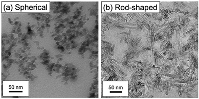
TEM observations of thin sections of the gels were conducted to assess the structure of the alumina aggregates within the ion gel. Fig. 4 presents the TEM images of cross-sections of the alumina/PIL DN ion gels, where the dark-coloured particles represent the alumina NPs. The TEM images of the ion gels with spherical alumina revealed that the primary particles of alumina formed clusters (Fig. 4a), while those of the rod-shaped alumina were aligned in parallel to form primary and secondary aggregates (Fig. 4b). The aggregate structures formed by the spherical and rod-shaped particles within the ion gels were thus significantly different.
Fig. 5 shows the stress–strain curves for the spherical alumina/PIL DN ion gels and rod-shaped alumina/PIL DN ion gels with different alumina concentrations. The stress–strain curves of the PIL ion gel comprising 47 wt% PC2im-TFSI and 53 wt% [C4mim][TFSI] (i.e. an alumina concentration of 0 wt%) are also provided. The results revealed that the mechanical strengths of the alumina/PIL DN ion gels were higher than those of the PIL SN ion gel, regardless of the shape of alumina particle. The mechanical properties of the spherical alumina/PIL DN ion gels and rod-shaped alumina/PIL DN ion gels are shown in Fig. 6. The results revealed that the fracture parameters, including strains, stresses, and energies, as well as Young's moduli, tended to increase with an increase in the spherical alumina concentration (Fig. 6a). The increase in the fracture stress and Young's modulus can be attributed to the increase in network density of the dendritic structure formed by alumina with an increase in alumina concentration. Moreover, it was hypothesised that there is a maximum effective alumina network amount for strength enhancement due to the negligible difference between the fracture energies at 12 and 14 wt%. Fig. S4 and S5 illustrate that the fracture strain decreased with increasing crosslinker concentration of the PIL network, regardless of the presence or the shape of alumina (ESI†). This suggests that the fracture strain can be influenced by the crosslinking density of the PIL network, which serves as a hidden length.38
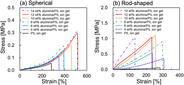 | ||
| Fig. 5 Stress–strain curves of (a) spherical and (b) rod-shaped alumina/PIL DN ion gels with different alumina concentrations. | ||
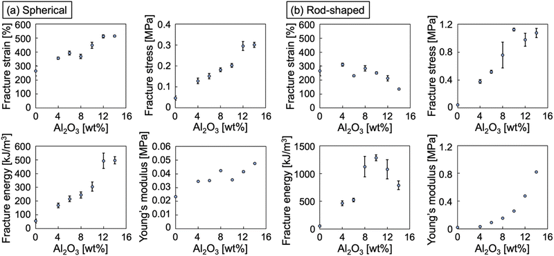 | ||
| Fig. 6 Mechanical properties of (a) spherical and (b) rod-shaped alumina/PIL DN ion gels with different alumina concentrations. | ||
Fig. 5b and 6b also revealed that the Young's moduli of the rod-shaped alumina/PIL DN ion gels increased with an increase in alumina concentration, thus indicating that the rod-shaped alumina stiffened the ion gels. Although the fracture strain remained almost constant, the fracture stress increased with an increase in alumina concentration up to 10 wt%. At alumina concentrations exceeding 10 wt%, the fracture strain decreased, and the fracture stress remained almost constant. This behaviour can be attributed to the formation of large aggregates due to the excess of alumina in the IL, which introduced critical cracks thus resulting in the breakage of ion gels during stretching. The fracture energy increased with an increase in alumina concentration up to 10 wt% but then tended to decrease at higher concentrations, thus indicating a toughness threshold, even in the case of rod-shaped alumina.
The oscillatory shear temperature-sweep viscoelasticity measurements were performed to determine Tg of ion gels. Tg was identified by the temperature corresponding to the peak top of tan![[thin space (1/6-em)]](https://www.rsc.org/images/entities/char_2009.gif) δ.39 The data from these measurements suggest that incorporating alumina into ion gels has a marginal impact on their Tg, which were determined as −24.8 °C for SN, −22.6 °C for spherical alumina DN, and −27.3 °C for rod-shaped alumina DN, as illustrated in Fig. S6 (ESI†). The ionic conductivities of the ion gels were also assessed using an impedance analyser. The results revealed that the introduction of alumina into the ion gels did not alter the ionic conductivities, which remained at approximately 10−3 S cm−1 at 30 °C, as illustrated in Fig. S7 (ESI†). Consequently, we assumed that the enhanced mechanical strength of the ion gels containing alumina NPs was attributed to the changes in their network structure rather than their chemical properties.
δ.39 The data from these measurements suggest that incorporating alumina into ion gels has a marginal impact on their Tg, which were determined as −24.8 °C for SN, −22.6 °C for spherical alumina DN, and −27.3 °C for rod-shaped alumina DN, as illustrated in Fig. S6 (ESI†). The ionic conductivities of the ion gels were also assessed using an impedance analyser. The results revealed that the introduction of alumina into the ion gels did not alter the ionic conductivities, which remained at approximately 10−3 S cm−1 at 30 °C, as illustrated in Fig. S7 (ESI†). Consequently, we assumed that the enhanced mechanical strength of the ion gels containing alumina NPs was attributed to the changes in their network structure rather than their chemical properties.
To elucidate the toughening mechanism of the ion gel upon the addition of alumina, cyclic tensile stress loading–unloading experiments were conducted for the PIL SN ion gel, spherical alumina/PIL DN ion gels, and rod-shaped alumina/PIL DN ion gels, as shown in Fig. 7. Regardless of the alumina shape, the alumina/PIL DN ion gels exhibited distinct hysteresis loops in the cyclic stress–strain curves, showing a softening behaviour of the ion gel when loading was applied (Fig. 7b and c), whereas the PIL SN ion gel did not exhibit such behaviour (Fig. 7a). The hysteresis loop observed in the stress–strain curve of the alumina/PIL DN ion gel can be attributed to the partial destruction of the alumina aggregates when subjected to loading, which is in accordance with the previously reported behaviour of silica NPs/PIL DN ion gels.30 These observations strongly suggested that the toughening mechanism in the alumina/PIL DN ion gel is attributed to energy dissipation stemming from the fracture of the alumina aggregate under a large strain.
 | ||
| Fig. 7 Cyclic tensile tests of (a) PIL SN, (b) spherical alumina/PIL DN, and (c) rod-shaped alumina/PIL DN ion gels. | ||
To compare the difference in the degree of energy dissipation by spherical and rod-shaped alumina, we calculated the energy dissipation per strain cycle during the cyclic tensile stress loading–unloading experiments, as shown in Fig. 8. The dissipated energy tended to increase with an increase in the number of cycles, irrespective of the alumina shape, thus indicating that the alumina network contributed to sustaining the loaded stress until the high elongation state.28 For the spherical alumina/PIL DN ion gel, the variation in the dissipated energy per cycle as a function of the concentration was minimal, while they were positively correlated in the case of the rod-shaped alumina/PIL DN ion gel. These results indicated that in the case of spherical alumina, the dendritic structure could develop with an increase in alumina concentration, whereas in the case of rod-shaped alumina, the size and the number of alumina aggregates could increase with an increase in alumina concentration.
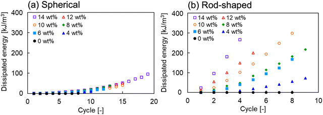 | ||
| Fig. 8 Dissipated energy of (a) spherical and (b) rod-shaped alumina/PIL DN ion gels, as a function of cycle. | ||
Ion gels with rod-shaped alumina exhibited higher fracture stresses and Young's moduli, but lower fracture strains than those with spherical alumina. In the case of spherical alumina, the dendritic alumina network spread throughout the gel contributes to an increase in fracture stresses and Young's moduli without hindering the elongation of the PIL when the ion gels are stretched. Conversely, rod-shaped alumina could form large aggregates, significantly increasing fracture stresses and Young's moduli. However, the breakage of these aggregates tends to facilitate crack propagation within the gel, resulting in reduced fracture strains. Overall, the difference in mechanical strength appeared to be governed by the distinctive network structures formed within the ion gel based on the alumina shape.
Conclusions
This study investigated the effect of the alumina shape on the mechanical properties of synthesized alumina/PIL DN ion gels. The results revealed that both spherical and rod-shaped alumina NPs significantly improved the mechanical strength of ion gels, although noticeable differences were attributed to the shapes of the nanoparticles, which influenced the structure of the alumina network. Spherical alumina led to a more consistent increase in the mechanical properties across different concentrations, similar to the previously reported results for silica NPs, while the rod-shaped alumina led to a stiffer ion gel and demonstrated a threshold for toughness improvement with diminishing returns beyond a specific concentration owing to the formation of large aggregates. The critical influence of the shape of the alumina on the macroscopic mechanical properties of the ion gels was evident, thus underscoring the necessity of optimising the nanoparticle shape and secondary aggregation structure for specific applications. The cyclic tensile tests and rheological behaviour analysis provided insights into the toughening mechanism of the ion gels and highlighted the role of energy dissipation through the partial destruction of alumina aggregates under strain. This behaviour is consistent with the DN principle, thus validating the effectiveness of the nanomaterial/polymer composite approach for enhancing the mechanical resilience of ion gels. In summary, we found that the complex interplay between the shape of the nanomaterials and macroscopic properties of ion gels, thus providing a pathway for the rational design of ion gels with tailored mechanical properties. Future work should delve deeper into optimising the nanoparticle characteristics and explore additional nanomaterials to expand the application range and performance of ion gels.Experimental section
Materials
Spherical alumina NPs (13 nm in diameter) were purchased from Tokyo Chemical Industry Co., Ltd (Tokyo, Japan). Rod-shaped alumina dispersion (10 wt%) in EA was kindly provided by Kawaken Fine Chemical Co., Ltd. The minor and major axes were 10 and 50 nm, respectively. The ionic liquid, [C4mim][TFSI], ionic liquid monomer [C2vim][TFSI], 1-vinylimidazole, 1,4-dibromobutane, ethanol, diethyl ether, and lithium bis(trifluoromethanesulfonyl)imide (LiTFSI) were purchased from FUJIFILM Wako Pure Chemical Corp. (Osaka, Japan) and used as received. Furthermore, 2-hydroxy-4′-(2-hydroxyethoxy)-2-methylpropiophenone (Ciba® IRGACURE® 2959), purchased from Ciba Specialty Chemicals (Switzerland), was used as a photoinitiator to synthesize the PC2im-TFSI network in an IL. Dimethyl sulfoxide-d6 was purchased from Sigma-Aldrich (Germany) and used as received. The deionised water used in all experiments was produced using an Elix UV purification system (Millipore, Japan). The chemical structures of [C4mim][TFSI], [C2vim][TFSI], Ciba® IRGACURE® 2959, [(Vim)2C4]Br2, and [(Vim)2C4][TFSI]2 are shown in Fig. S1 (ESI†).Synthesis of [(Vim)2C4][TFSI]2 as a cross-linking reagent containing ionic liquid groups
The cross-linking reagent, [(Vim)2C4][TFSI]2, containing ionic liquid groups, was synthesised by reacting 1-vinylimidazole with 1,4-dibromobutane, followed by an anion exchange reaction with LiTFSI (Scheme S1, ESI†). In a round-bottom flask (300 mL) that had been dried and purged with argon, 1-vinylimidazole (0.20 mol, 18.1 mL) was dissolved in ethanol (15.0 mL). Subsequently, 1,4-dibromobutane (0.11 mol, 13.6 mL) was added dropwise to the flask and the mixture was stirred at 70 °C under an argon atmosphere for 24 h. The reaction mixture was precipitated thrice in ethyl acetate (300 mL) to remove any unreacted reagents. The purified product was dried at 50 °C under reduced pressure over night, to obtain [(Vim)2C4]Br2 (30.2 g, yield: 75% according to the proton nuclear magnetic resonance (1H NMR) spectrum in Fig. S2a (ESI†). The anion exchange reaction of [(Vim)2C4]Br2 with LiTFSI was then performed by mixing an aqueous solution (60 mL) containing [(Vim)2C4]Br2 (7.4 mmol, 3.00 g) with another aqueous solution (60 mL) containing LiTFSI (16.5 mmol, 4.73 g). The resulting mixture was stirred at room temperature for 24 h under an argon atmosphere to exchange the Br2 counter anion with the [TFSI]2 anions. The resulting [(Vim)2C4][TFSI]2 was washed thrice with pure water (100 mL) and freeze-dried for 24 h to remove any residual salt and obtain [(Vim)2C4][TFSI]2 (4.7 g, yield: 78.5% according to the 1H NMR spectrum in Fig. S2b (ESI†)). The successful anion exchange from Br to TFSI was confirmed by the shift in peak from a (9.46 ppm, 2H in Fig. S2a, ESI†) to a' (9.40 ppm, 2H in Fig. S2b, ESI†).Rheological measurements of the alumina/[C4mim][TFSI] dispersion
The alumina/[C4mim][TFSI]/EA dispersions were prepared according to the following procedure which uses as an example an alumina concentration of 0.85 vol%. The spherical alumina NPs (0.12 g), [C4mim][TFSI] (3.5 g), and EA (1.2 mL) were mixed using a vortex mixer to obtain a homogeneous spherical alumina/[C4mim][TFSI]/EA dispersion. Ten wt% rod-shaped alumina dispersion in EA (1.2 g) was mixed with [C4mim][TFSI] (3.5 g) using a vortex mixer, and then dried under reduced pressure with stirring to evaporate the excess EA. The appropriate amount of EA was added to bring the total EA volume to 1.2 mL, and uniform rod-shaped alumina/[C4mim][TFSI]/EA dispersions were prepared. The amounts of reagent for other alumina concentrations are listed in Tables S1 and S2 (ESI†). Viscosities and viscoelasticities of the alumina/[C4mim][TFSI]/EA dispersions were measured using a controlled stress rheometer (MCR302, Anton Paar, Japan). The viscosity dependence of the shear of the alumina/[C4mim][TFSI]/EA dispersion as a sample was evaluated using a rheometer with a parallel-plate geometry (PP50; diameter = 50 mm, gap = 0.3 mm) at 20 °C. Similar measurements were conducted by employing [C4mim][TFSI]/EA mixture as the control. After pre-shearing at 1000 s−1 for 60 s, the change in viscosity of the solution was measured as a function of shear rate from 1000 to 0.01 s−1 and then from 0.01 to 1000 s−1. Frequency-sweep viscoelasticity (G′ and G′′) measurements of the alumina/[C4mim][TFSI]/EA dispersion were also performed as a function of frequency from 0.01 to 100 Hz at a strain of 0.1% using the same rheometer geometry. The limiting torque on the MCR302 rheometer is approximately 0.5 μN m; data corresponding to torque values below this limit was trimmed.Preparation of the alumina/PIL DN ion gels
Alumina/PIL DN ion gels were prepared via the photopolymerization of an ionic liquid monomer ([C2vim][TFSI]) in the presence of the ionic liquid ([C4mim][TFSI]), EA, and alumina. The alumina/PIL DN ion gels were prepared according to the following procedure which uses as an example an alumina concentration of 10 wt%. To prepare spherical alumina/PIL DN ion gels, alumina NPs (0.30 g) and [C4mim][TFSI] (3.5 g) were mixed in a vortex mixer. In the case of using rod-shaped alumina, 10 wt% rod-shaped alumina dispersion in EA (3.0 g) was mixed with [C4mim][TFSI] (3.5 g) using a vortex mixer, and then dried under reduced pressure with stirring to remove the excessive EA. [C2vim][TFSI] (3.0 g) as a monomer, [(Vim)2C4][TFSI]2 (0.021 g) as a cross-linking agent, IRGACURE® 2959 (0.0016 g) as a photoinitiator, and EA (total volume 1.2 mL) were then added, mixed using a vortex mixer, and stirred to prepare the precursor solution. The amounts of reagent for other crosslinker concentrations or alumina concentrations are listed in Tables S3–S5 (ESI†). The precursor solution was injected into a mould composed of two glass plates with an FEP film and a PTFE spacer with 1-mm thickness and was irradiated with 365 nm UV light for 13 h (1820 μW cm−2). The product was dried in vacuum at 40 °C for more than 3 h to remove EA. The IL concentration after drying was fixed at 53 wt%.Measurement of the mechanical properties
The mechanical properties of the ion gels were evaluated using an automatic recording universal testing instrument (EZ Test EZ-SX 500 N, Shimadzu Co., Japan) at 25 °C. Dumbbell-shaped specimens with lengths, widths, and thicknesses of 35, 2, and 1 mm, respectively, were used for the tensile tests. The fabricated sample was attached to the instrument at 15 mm between the jigs. The uniaxial stretching test was conducted by stretching the sample at a constant strain rate of 50 mm min−1. The stress–strain curves were recorded automatically until the specimens broke. The fracture stresses, strains, and energies in addition to the Young's moduli of the ion gels were obtained as mean values of triplicate measurements for each sample. In the cyclic tensile test, loading and unloading operations were performed, and the stress–strain curves were recorded until the sample broke while gradually increasing the stretching strain at intervals of 0.3.Oscillatory shear temperature sweep viscoelasticity measurement of alumina/PIL DN ion gels
Temperature-sweep viscoelasticity measurements of the ion gels were performed with a parallel-plate geometry (PP25; diameter = 25 mm, gap = 1 mm) using a controlled stress rheometer (MCR302, Anton Paar, Japan). The measurements were performed in the temperature range of −80 to 160 °C, a frequency of 1 Hz, and a strain of 0.1%. Tg was determined as the temperature at the peak top of tan![[thin space (1/6-em)]](https://www.rsc.org/images/entities/char_2009.gif) δ.
δ.
TEM observations of alumina/PIL DN ion gel
To confirm the morphology of alumina in the PIL ion gel, the samples were observed by a TEM (JEM-2100F, JEOL). A cubic sample of the ion gel (1 mm in size) was immersed in a sufficient amount of EA for 24 h to exchange the [C4mim][TFSI] in the sample by EA. The sample was then immersed in a mixture of a precursor solution of UV-curable resin and EA (1/1, w/w) for 24 h, followed by immersion in a precursor solution of UV-curable resin for 12 h to completely exchange the EA for the precursor solution. The sample in the precursor solution was poured into a silicon mould and cured under a UV light (λ = 365 nm) for 1 h. The resin block embedded in the gel was then thin-sectioned using an ultramicrotome (UC7, Leica Microsystems GmbH, Germany), and 100 nm-thick sections were collected on a copper mesh TEM grid. The sample was observed using TEM at an electron gun acceleration voltage of 100 kV.Ionic conductivity measurement of gel films
The ionic conductivity of the gel films was measured by means of the complex impedance measurements with stainless steel electrodes, using a computer-controlled impedance analyser (LCR meter IM3536, HIOKI) over the frequency range from 4 Hz to 10 MHz at an AC amplitude of 1 V. A film (1 cm2 area and 1 mm thickness) was sandwiched between stainless steel electrodes and subjected to the impedance measurements. The measurements were conducted at controlled temperatures while heating from −20 to 120 °C in a temperature chamber. The ionic conductivity (σ [mS cm−1]) was then calculated as σ = l/(Ra), where l is the sample thickness [cm], a is the surface area of the sample [cm2], and R is the bulk resistance determined from the real part of the impedance, Z′, in the high-frequency plateau [Ω].Author contributions
Y. M., T. W., C. G. L., and T. O. designed the experiments. Y. M. and T. W. performed the experiments and analysed the data. Y. M., T. W., C. G. L., and T. O. interpreted the results and wrote the manuscript. T. W. and T. O designed the research.Conflicts of interest
There are no conflicts to declare.Acknowledgements
This work was partly supported by the JSPS KAKENHI (grant numbers: JP20KK0325 and JP21H04629), the New Energy and Industrial Technology Development Organization (NEDO) (grant number: JPNP20004), the Young Faculty Promotion Program (2023) at Okayama University, and the TOKUYAMA SCIENCE FOUNDATION. We also thank Kawaken Fine Chemicals Co., Ltd, Japan, for supplying the rod-shaped alumina dispersion in ethyl acetate.References
- Y. Wang, Y. Chen, J. Gao, H. G. Yoon, L. Jin, M. Forsyth, T. J. Dingemans and L. A. Madsen, Adv. Mater., 2016, 28, 2571–2578 CrossRef CAS PubMed
.
- D. M. Fox, J. W. Gilman, A. B. Morgan, J. R. Shields, P. H. Maupin, R. E. Lyon, H. C. De Long and P. C. Trulove, Ind. Eng. Chem. Res., 2008, 47, 6327–6332 CrossRef CAS
.
- J. Zhang, E. Kamio and A. Matsuoka, Ind. Eng. Chem. Res., 2022, 61, 4648–4658 CrossRef CAS
.
- M. G. Cowan, D. L. Gin and R. D. Noble, Acc. Chem. Res., 2016, 49, 724–732 CrossRef CAS PubMed
.
- B. E. Gurkan, J. C. de la Fuente, E. M. Mindrup, L. E. Ficke, B. F. Goodrich, E. A. Price, W. F. Schneider and J. F. Brennecke, J. Am. Chem. Soc., 2010, 132, 2116–2117 CrossRef CAS PubMed
.
- W. He, F. Zhang, Z. Wang, W. Sun, Z. Zhou and Z. Ren, Ind. Eng. Chem. Res., 2016, 55, 12616–12631 CrossRef CAS
.
- J. E. Bara, E. S. Hatakeyama, D. L. Gin and R. D. Noble, Polym. Adv. Technol., 2008, 19, 1415–1420 CrossRef CAS
.
- S. P. M. Ventura, A. M. M. Gonçalves, T. Sintra, J. L. Pereira, F. Gonçalves and J. A. P. Coutinho, Ecotoxicology, 2013, 22, 1–12 CrossRef CAS PubMed
.
- Y. Kamiyama, R. Tamate, K. Fujii and T. Ueki, Soft Matter, 2022, 18, 8582–8590 RSC
.
- H. Wang, Z. Wang, J. Yang, C. Xu, Q. Zhang and Z. Peng, Macromol. Rapid Commun., 2018, e1800246 CrossRef PubMed
.
- S. Imaizumi, H. Kokubo and M. Watanabe, Macromolecules, 2012, 45, 401–409 CrossRef CAS
.
- X. Liu, B. He, Z. Wang, H. Tang, T. Su and Q. Wang, Sci. Rep., 2014, 4, 6673 CrossRef PubMed
.
- X. Yang, F. Zhang, L. Zhang, T. Zhang, Y. Huang and Y. Chen, Adv. Funct. Mater., 2013, 23, 3353–3360 CrossRef CAS
.
- T. Y. Kim, H. W. Lee, M. Stoller, D. R. Dreyer, C. W. Bielawski, R. S. Ruoff and K. S. Suh, ACS Nano, 2011, 5, 436–442 CrossRef CAS PubMed
.
- S. Hong, Y. Yuan, C. Liu, W. Chen, L. Chen, H. Lian and H. Liimatainen, J. Mater. Chem., 2020, 8, 550–560 CAS
.
- Y. J. Son, J. W. Bae, H. J. Lee, S. Bae, S. Baik, K.-Y. Chun and C.-S. Han, J. Mater. Chem. A, 2020, 8, 6013–6021 RSC
.
- L. Rong, X. Xie, W. Yuan and Y. Fu, ACS Appl. Mater. Interfaces, 2022, 14, 29273–29283 CrossRef CAS PubMed
.
- C. S. Patrickios and K. Matyjaszewski, Polym. Int., 2021, 70, 10–13 CrossRef CAS
.
- S. Ishii, H. Kokubo, K. Hashimoto, S. Imaizumi and M. Watanabe, Macromolecules, 2017, 50, 2906–2915 CrossRef CAS
.
- H. Asai, K. Fujii, T. Ueki, T. Sakai, U.-I. Chung, M. Watanabe, Y.-S. Han, T.-H. Kim and M. Shibayama, Macromolecules, 2012, 45, 3902–3909 CrossRef CAS
.
- K. Fujii, H. Asai, T. Ueki, T. Sakai, S. Imaizumi, U.-I. Chung, M. Watanabe and M. Shibayama, Soft Matter, 2012, 8, 1756–1759 RSC
.
- R. Tamate, K. Hashimoto, T. Horii, M. Hirasawa, X. Li, M. Shibayama and M. Watanabe, Adv. Mater., 2018, 30, 1–7 CrossRef PubMed
.
- Y. Kamiyama, R. Tamate, T. Hiroi, S. Samitsu, K. Fujii and T. Ueki, Sci. Adv., 2022, 8, eadd0226 CrossRef CAS PubMed
.
- W. Li, L. Li, Z. Liu, S. Zheng, Q. Li and F. Yan, Adv. Mater., 2023, 35, e2301383 CrossRef PubMed
.
- M. Wang, P. Zhang, M. Shamsi, J. L. Thelen, W. Qian, V. K. Truong, J. Ma, J. Hu and M. D. Dickey, Nat. Mater., 2022, 21, 359–365 CrossRef CAS PubMed
.
- H. Arafune, S. Honma, T. Morinaga, T. Kamijo, M. Miura, H. Furukawa and T. Sato, Adv. Mater. Interfaces, 2017, 4, 1700074 CrossRef
.
- E. Kamio, T. Yasui, Y. Iida, J. P. Gong and H. Matsuyama, Adv. Mater., 2017, 29, 1704118 CrossRef PubMed
.
- T. Yasui, E. Kamio and H. Matsuyama, Langmuir, 2018, 34, 10622–10633 CrossRef CAS PubMed
.
- T. Yasui, S. Fujinami, T. Hoshino, E. Kamio and H. Matsuyama, Soft Matter, 2020, 16, 2363–2370 RSC
.
- T. Watanabe, R. Takahashi and T. Ono, Soft Matter, 2020, 16, 1572–1581 RSC
.
- T. Watanabe, E. Oe, Y. Mizutani and T. Ono, Soft Matter, 2023, 19, 2745–2754 RSC
.
- C. Zeng, S. Lu, L. Song, X. Xiao, J. Gao, L. Pan, Z. He and J. Yu, RSC Adv., 2015, 5, 35773–35782 RSC
.
- Z. Guo, T. Pereira, O. Choi, Y. Wang and H. Thomas Hahn, J. Mater. Chem., 2006, 16, 2800–2808 RSC
.
- K. Ueno, K. Hata, T. Katakabe, M. Kondoh and M. Watanabe, J. Phys. Chem. B, 2008, 112, 9013–9019 CrossRef CAS PubMed
.
- K. Ueno, Polym. J., 2018, 50, 951–958 CrossRef CAS
.
- A. Scotti, M. Brugnoni, C. G. Lopez, S. Bochenek, J. J. Crassous and W. Richtering, Soft Matter, 2020, 16, 668–678 RSC
.
- H. Senff and W. Richtering, Colloid Polym. Sci., 2000, 278, 830–840 CrossRef CAS
.
- J. P. Gong, Soft Matter, 2010, 6, 2583–2590 RSC
.
- K. Sakurai, T. Maegawa and T. Takahashi, Polymer, 2000, 41, 7051–7056 CrossRef CAS
.
Footnote |
| † Electronic supplementary information (ESI) available. See DOI: https://doi.org/10.1039/d3sm01626a |
| This journal is © The Royal Society of Chemistry 2024 |

