
 Open Access Article
 This Open Access Article is licensed under a Creative Commons Attribution-Non Commercial 3.0 Unported Licence
The association of structural chirality and liquid crystal anchoring in polymer stabilized cholesteric liquid crystals†
Brian P.
Radka
a,
Taewoo
Lee
c,
Ivan I.
Smalyukh
 bcd and
Timothy J.
White
*ab
bcd and
Timothy J.
White
*ab
aDepartment of Chemical and Biological Engineering, University of Colorado, Boulder, CO 80309, USA. E-mail: timothy.j.white@colorado.edu
bMaterials Science and Engineering Program, University of Colorado, Boulder, CO 80309, USA
cDepartment of Physics, University of Colorado, Boulder, CO 80309, USA
dRenewable and Sustainable Energy Institute, National Renewable Energy Laboratory and University of Colorado, Colorado, Boulder, CO 80309, USA
First published on 23rd January 2024
Abstract
Polymer stabilized cholesteric liquid crystals (PSCLCs) are electrically reconfigurable reflective elements. Prior studies have hypothesized and indirectly confirmed that the electro-optic response of these composites is associated with the electrically mediated distortion of the stabilizing polymer network. The proposed mechanism is based on the retention of structural chirality in the polymer stabilizing network, which upon deformation is spatially distorted, which accordingly affects the pitch of the surrounding low molar-mass liquid crystal host. Here, we utilize fluorescent confocal polarized microscopy to directly assess the electro-optic response of PSCLCs. By utilizing dual fluorescent probes, sequential imaging experiments confirm that the periodicity of the polymer stabilizing network matches that of the low molar-mass liquid crystal host. Further, we isolate distinct ion-polymer interactions that manifest in certain photopolymerization conditions.
Introduction
Liquid crystals (LCs) are widely studied optical materials. The positional ordering of LC molecules manifests anisotropic properties (electrical, optical, etc.) that are dependent on the relative orientation of the molecules and stimuli.1–12 Amongst calamitic-type LCs (rod-shaped molecules), we are concerned here with the nematic and cholesteric phases. Nematic LCs (NLCs) self-align with the long axis pointed towards a general direction known as the director. It is well-established that the addition of chiral dopants to nematic LCs is a straightforward route to prepare the cholesteric phase. Here, the chirality of the dopant molecules is transferred to the nematic LC which forms a helical twist of the director. The twisted orientation can be either right or left-handed depending on the choice of chiral dopants.13–21The periodic variation in the director in the cholesteric LC (CLC) phase nascently forms a one-dimensional photonic crystal with a continuous, sinusoidal change in the refractive index along the direction of the helical axis.22,23 This periodicity results in a wavelength and polarization selective reflection dependent on the refractive properties of the media, pitch length (P), and handedness of the director rotation of the CLC.24–31Eqn (1) and (2) below define the association of reflection wavelength (where λc is the central wavelength of reflection) and bandwidth (Δλ) at normal incidence, where navg is the average refractive index and Δn is the birefringence.
| λc = navgP | (1) |
| Δλ = ΔnP | (2) |
Prior examination of stimuli-induced tuning of the selective reflection of CLCs have a number of drawbacks including slow and inefficient stimuli response (i.e. thermal tuning,32–37 optically active dopants38–52) or a loss of reflectivity that is not easily recoverable (i.e. electrical switching).53 The use of polymer stabilized cholesteric liquid crystals (PSCLCs) made with liquid crystals exhibiting negative dielectric anisotropy (Δε < 0) are appealing to realize dynamic optical elements due to the coupling to electric stimulus, retention of optical properties, and passive reversibility in the off state.
The mechanism for tuning PSCLCs relies on three key attributes. First, the CLC host anchors to the polymer stabilizing network (PSN).54,55 Second, electric field interaction between ions tethered on or within the polymer stabilizing network.56,57 Third, the mechanical properties of the polymer network.58–60 This manuscript is focused on directly elucidating the coupling between the structurally chiral polymer stabilized network and the CLC host.
Expanding further, nearly all prior studies observe electro-optic response in PSCLCs formulated with Δε < 0 NLC.61–66 Upon application of an electric field, the dipole moments of the LC molecules in the media are already aligned to the field direction and do not reorient. Prior experiments confirm the PSN retains structural chirality.67,68 By structural chirality, we refer to the templated chirality observed in the PSN's fibril architecture, often prepared from achiral LC monomers.69,70 In this way, the interaction of the PSN and the CLC host can be thought of as through-thickness surface anchoring. Finally, the directionality of the electro-optic response has been shown to be sensitive to the direction of the applied DC bias. Further, the tuning is not observed when the PSCLCs are subject to AC field.
Accordingly, the working hypothesis is that the electro-optic response is attributed to ions trapped on or within the PSN that couple with the applied electric field to impart a mechanical force on the polymer network. Due to the elastic nature of the polymer network, when the PSN is bound between two rigid substrates, this force causes a deformation of the polymer network parallel to the electric field, with certain regions showing expansion of the polymer network pitch while other regions showing compression or no change. As seen in eqn (1) and (2), an observable change in P will vary the reflective properties. Upon removal of the electric field, the elastic properties of the PSN restore the pitch of the PSCLCs and allow the reflection to return to the original spectral wavelength.
The various optical responses observed in PSCLCs (i.e. bandwidth broadening, red or blue-shift tuning) can then be thought of as manifestations of this mechanism with variation in the nature and distribution of the deformation of the PSN. Prior studies have investigated the pitch deformation of PSCLCs under an electric field with fluorescent confocal polarized microscopy (FCPM). FCPM is an adaption of confocal microscopy utilizing a fluorescent probe in conjunction with a linearly polarized excitation capable of imaging three-dimensional patterns dependent on orientational order.71 FCPM's advantage over traditional microscopy techniques is through a specific optical setup that reduces the signal above and below the intended focal point, increasing the depth dependent resolution.72 If the fluorescent probe is capable of aligning with the host LC and exhibits dichroic absorbance, FCPM can reveal the LC director orientation in space.71–76
Previous experiments imaged the pitch in PSCLCs with multi-photon excitation fluorescence polarizing microscopy either used a dichroic dye in the host LC or a monoacrylate fluorescent dye, producing high intensity signals at depths where the excitation beam and director are parallel, and minima when they are orthogonal.64,67,77,78 However, these studies did not allow for correlating the director of the LC host and the stabilizing network in unison, in addition to only focusing on one aspect of the optical response.
Accordingly, this report details an examination utilizing FCPM based on two individual fluorescent probes, one bound to the PSN and the other in the CLC host. The two signals were read out in the optical setup shown in Fig. 1(a). The first dichroic mirror (DM1) reflects the excitation beam to the sample while allowing the emission signals to pass through, the second dichroic mirror (DM2) separates the two emission signals produced by the different dye molecules, sending them to individual detectors. The molecular structures, absorption, and emission for the fluorescent molecules in a polymer stabilized nematic liquid crystal are detailed in Fig. 1(b and c).
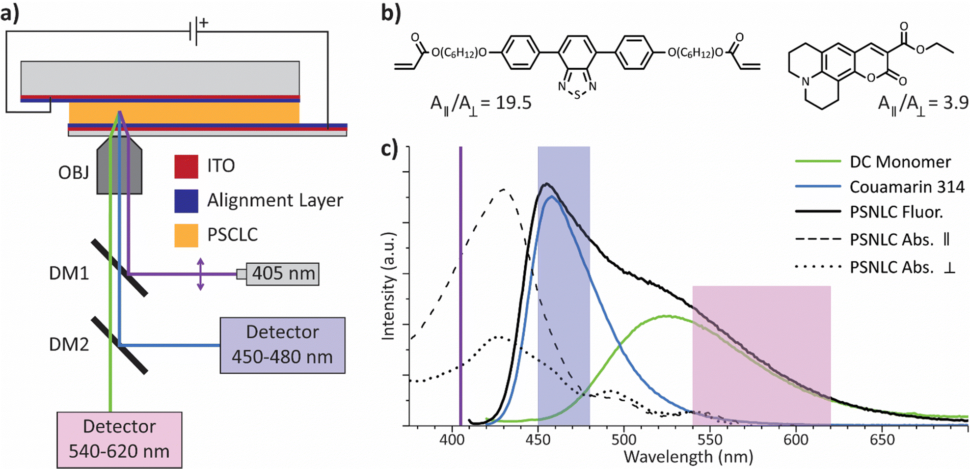 | ||
| Fig. 1 (a) An illustration of the optical imaging setup utilized here. Voltage is applied by electrical contact (DC field) with the PSCLC sample prepared in glass substrates with ITO layers on each side. The positive electrode was always located on the side of the objective. Abbreviations in the illustration are objective lens (OBJ), dichroic mirror (DM), and indium tin oxide (ITO). (b) The chemical structures of the fluorescent probes. (Inset) The dichroic ratios (A||/A⊥) of the dyes measured at 405 nm in a polymer stabilized nematic liquid crystal (PSNLC), the scans used for this calculation are shown in Fig. S3 (ESI†). (left) Dichroic (DC) monomer and (right) coumarin-314. (c) Absorption and fluorescent spectra of the PSNLC. The purple line emphasizes the excitation wavelength (405 nm) used in the confocal imaging and fluorescence emission measurements. The highlighted regions correspond to the detection wavelengths used to separate the signals in the FCPM. The green and blue lines represent the deconvolution of the fluorescent signal of the dichroic dyes. | ||
Results and discussion
Here we are concerned with associating the electrically mediated deformation of the PSN with the change in the pitch of the host LC through surface anchoring against the PSN, and its correlation with electro-optic behavior. Accordingly, we have studied a series of different PSCLC formulations analogous to formulations that produce distinct optical changes in the electromagnetic range of visible light (bandwidth broadening, red-shift tuning, blue-shift tuning). These formulations differ only by the relative initial pitch length (Po), which have been shown to respond in a similar manner to their shorter pitch length analogs, with the relative response dependent only on the polymerization conditions.79,80In Fig. 2 the separated signal for a PSCLC under differing voltages can be seen with the signals for the host CLC (Fig. 2(a and b)), measured in the spectral range of 450–480 nm according to the fluorescence of coumarin-314, and the PSN (Fig. 2(c and d)), measured between 540–620 nm to capture the signal produced by the dichroic (DC) monomer. The samples are oriented with the positive electrode positioned at the top of the images in Fig. 2(a and c) and on the left for Fig. 2(b and d). In this PSCLC sample it can be easily observed that the polymer network has translated towards the negative electrode. This is highlighted by the higher signal intensity of the PSN near the negative electrode in Fig. 2(d) as voltage increases indicating a higher concentration of PSN in this region. Unlike the DC monomer the coumarin dye is able to flow freely in the system, such that the concentration is highly decoupled from the localized concentration of the PSN, especially given the relative low overall concentration of the polymer network compared to the host LC. These measurements confirm our experimental setup and conditions as it should be noted that there is minimal bleed through between the two signals, the increase in the PSN signal is not observed in the host CLC signal.
 | ||
| Fig. 2 FCPM of a PSCLC under various voltages with the signal separated between the (a) and (b) host CLC and (c) and (d) PSN. (a) and (c) Images from a vertical slice of the 3D FCPM image with different voltages applied (i) 0 V μm−1, (ii) 0.5 V μm−1, (iii) 1.0 V μm−1, (iv) 1.5 V μm−1, the positive electrode is located at the top of the images. (b) and (d) Normalized averaged fluorescent intensity across the 3D space versus depth for different applied voltages with the positive electrode located at the left side of the graph. The legend in (b) applies to both (b) and (d) accordingly. (a) and (b) The fluorescent signal for the host CLC is measured at 450–480 nm while (c) and (d) the fluorescent signal of the PSN is measured at 540–620 nm. | ||
It can also be observed in the intensity curves in the regions near the negative electrode, corresponding to the region with the highest compression of the polymer network and therefore shortest pitch, that both signals no longer exhibit local minima and maxima. This is not a result of the PSN rotating and aligning in a single orientation relative to the excitation beam but rather a compression of the pitch to a length close to the depth resolution of the FCPM imaging system. It should be noted that while nearing the region below the system depth resolution the PSN and host CLC still exhibit oscillation in their signals observed as inflection points. Noting the peak-to-peak distance for both the host CLC and the PSN we can see the pitch length increasing near the positive electrode as the voltage increases. This would all indicate that a net positive charge is acting on the polymer network, which matches prior published works.64,67
In order to inspect the correlation between the host CLC and PSN it is necessary to compare the intensity spectra in a more quantitative manner. To this end we can find the roots of the first and second derivative of the intensity signal to determine the local maxima/minima and points of inflection respectively. These calculated values will be used as points of interest in order to determine the degree of correlation between the host CLC and PSN. Prior assumptions into the mechanism for the electro-optic response of PSCLCs predicted the chirality of the polymer network will anchor and change the pitch of the host CLC. To confirm this the corresponding minima, maxima, and inflection points are plotted between the host CLC and PSN (Fig. 3). If the anchoring between the two is sufficiently strong there should be a linear dependence and, in fact, those points would be exactly equal for both signals. This relationship is confirmed in Fig. 3, for each voltage applied the location of the corresponding points of interest are almost exactly equal. When compared to the ideal relationship (where all the values for the CLC host and the PSN are equal), the coefficient of determination (R2) is almost exactly 1 for all voltages applied. It is notable that even in the regions where minima and maxima are no longer observable that the points of inflection of the PSN still correspond almost exactly to the points of inflection of the host CLC.
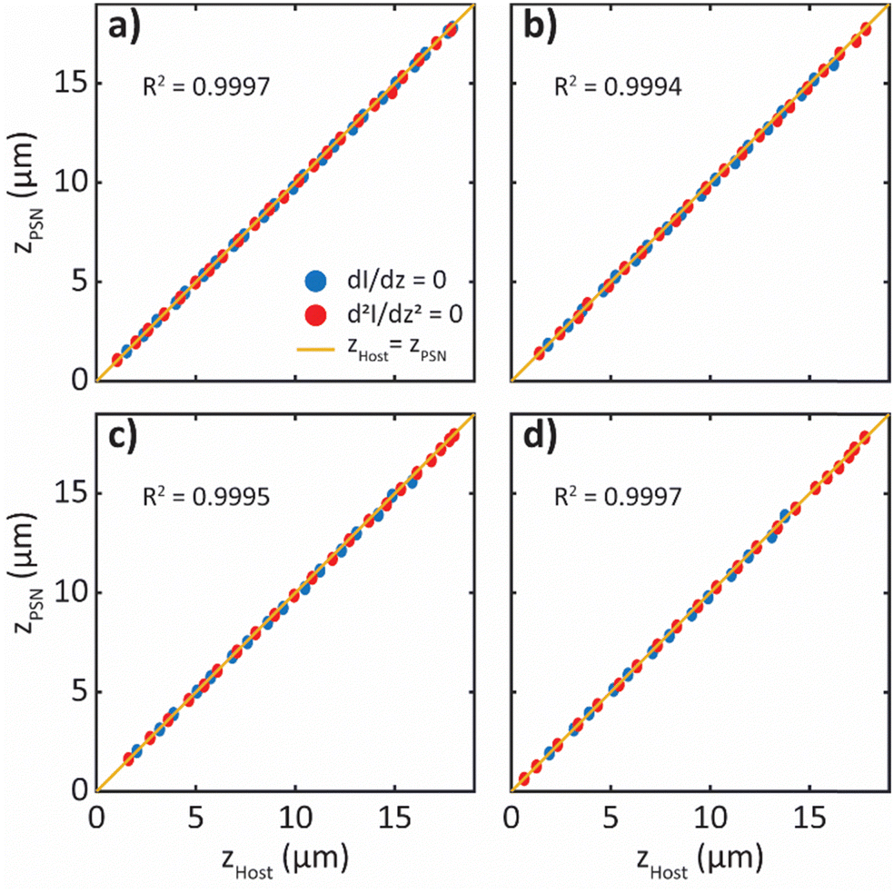 | ||
| Fig. 3 Comparison of the points of interest of the host CLC and PSN fluorescent intensity signal. (a)–(d) The x axis is the depth location of points of interest in the CLC host (ZHost), the y-axis is the depth location of points of interest in the PSN (ZPSN). The location of the minima and maxima (blue) were calculated with the roots of the first derivative (dI/dz = 0), the points of inflection (red) were calculated with the roots of the second derivative (d2I/dz2 = 0). The R2 value inset corresponds to the coefficient of determination for the data points compared to the idealized correlation (yellow), ZHost = ZPSN. This data is from the same sample as shown in Fig. 2, with applied voltages being (a) 0 V μm−1, (b) 0.5 V μm−1, (c) 1.0 V μm−1, (d) 1.5 V μm−1. | ||
This relationship also holds for samples that are polymerized at higher temperatures that lock in a different initial pitch lengths (Po) from what is observed at room temperature (Fig. 4). It is known that heating a CLC can alter the pitch length and is dependent on the mesophase properties of the LC host and the selection of chiral dopant.32–34,53 Due to the anchoring properties of the PSN after a thermally tuned sample is polymerized and returned to room temperature the pitch length during polymerization is retained.55,81–83 This results in the pitch length in the PSCLC beginning farther away from the intrinsic chirality of the mixture at room temperature even before voltage is applied. In the samples prepared in Fig. 4 the sample polymerized at room temperature (Fig. 4(a–c)) has an initial half pitch length of 2.3 μm while the second sample polymerized at 60 °C (Fig. 4(d–f)) has an initial pitch length of 2.7 μm, approximately a 17% increase in pitch length. Both samples exhibited very similar pitch deformations vs. depth (Fig. S4, ESI†) with both samples reaching a max pitch length roughly 55% larger than Po and a maximum compression of roughly 45% for each, both samples were only taken to 2.0 V μm−1 due to degradation at 2.5 V μm−1. The 55% increase in pitch length of the sample polymerized at 60 °C is equivalent to an 82% increase in the pitch compared to the intrinsic pitch length observed at room temperature. Therefore, the tuning range of the PSCLCs in our studies appear to be limited by the mechanical properties of the PSN not by the strength of the surface anchoring.
 | ||
| Fig. 4 PSCLCs formulated with 3 wt% of left-handed chiral dopant S811, 6 wt% LC monomer, and 0.5 wt% radical photoinitiator I-369, polymerized at (a)–(c) 22 °C and (d)–(f) 60 °C. FCPM signal intensity vs. depth at various voltages are shown for the (a) and (d) host CLC and (b) and (e) PSN. (c) and (f) Correlation between the points of interest ((blue) roots of the first derivate, (red) roots of the second derivative) for both samples comparing the CLC host (ZHost) and the PSN (ZPSN) at various voltages (i) 0 V μm−1, (ii) 0.5 V μm−1, (iii) 1.0 V μm−1, (iv) 1.5 V μm−1, (v) 2.0 V μm−1. The R2 value inset corresponds to the coefficient of determination for the data points compared to the idealized correlation (ZHost = ZPSN). | ||
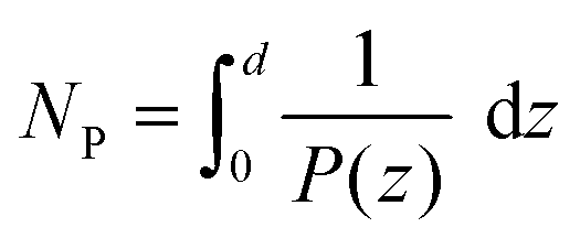
Now that the relationship between the director rotation of the host CLC and PSN has been shown it is suitable to use the minima, maxima, and inflection points to determine the pitch as a function of depth for differing PSCLC formulations that would exhibit different electro-optic responses. To this end we compare three samples in Fig. 5 that are representative of PSCLCS that would produce bandwidth broadening, red-shift tuning, and blue-shift tuning respectively. The pitch length was calculated using the distance between nearest neighbor points of interest from each signal individually, then the combined calculated data set was spline fit to see the depth dependent pitch variation. To validate the fitting eqn (3) was used to calculate the total number of pitches (NP) in the sample, where P(z) is the calculated pitch as a function of depth and d is the total cell gap distance:
 | (3) |
 | ||
| Fig. 5 Half pitch length (P/2) vs. depth under different electric field strengths (noted in inset legends), for all samples the positive electrode is located on the left side of the graph. Each sample has unique polymerization conditions to produce the specific response, all samples contain 6 wt% LC monomer in a custom eutectic CLC mixture polymerized with exposure to a 365 nm floodlight. (a) Bandwidth broadening sample produced with the inclusion of 0.5 wt% of the radical photoinitiator I-651 polymerized at 50 mW cm−2 for 10 min. (b) Red-shift tuning samples produced with the inclusion of 0.5 wt% of the radical photoinitiator I-369 polymerized at 50 mW cm−2 for 10 min. (c) Blue-shift tuning samples produced with the inclusion of 1.5 wt% of I-369 at 250 mW cm−2 for 30 min. | ||
In the absence of rotation of the PSN the value would be a constant, this was confirmed for all the samples shown in Fig. 5.
The three separate electro-optic responses shown in Fig. 5 are bandwidth broadening (a), red-shift tuning (b), and blue-shift tuning (c). For all three responses the positive electrode is located on the left of the graph (depth equals 0). Other than the pitch length (Po ≈ 3 μm) and inclusion of the dichroic dyes these formulations are identical to typical samples that would be formulated for their reflection to appear in the visible or near IR region (Po ≈ 0.300–1.5 μm). Despite very similar compositions, photoinitiator choice and polymerization conditions create unique pitch deformations, and therefore distinct electro-optic responses under voltage, where the specific conditions are noted in the caption for Fig. 5.
Bandwidth broadening results in an increase in the bandwidth of reflection that cannot be accounted for through a uniform pitch increase (eqn (1) and (2)). It would be expected that in order for the response to occur there needs to be a balance of regions with pitch expansion and compression. Previous attempts at modelling this response had predicted a linear deformation.64 However, that is not the case, as seen in Fig. 5(a) the pitch deformation in a broadening sample is due to a significant change in the pitch length from the regions near both the electrodes, with limited change in the pitch length in the center.
In Fig. 5(b) a red-shifting sample is examined, at low voltages the deformation looks very similar to the broadening sample in Fig. 5(a), which is expected from previous electro-optic experiments where red-shifting samples begin with slight broadening before the reflection begins to tune. In addition, we observe an expansion of pitch near the positive electrode, and compression near the negative electrode, indicating red-shifting along with bandwidth broadening are cation mediated. However, at higher voltages the similarity in deformation begins to diverge. The red-shifting samples see pitch expansion over a much larger depth, with more of a plateau in the expanded region. This is sensible due to the retention of a narrower bandwidth reflection seen in these samples, from optical calculations it has been shown that to maintain an efficient and narrow bandwidth reflection it is necessary to have a certain number of pitches in a row, for high birefringence CLCs that number is accepted as approximately 10.24,25,28,84 To balance the larger expanded region the pitch compression occurs over a shorter region with a larger slope (dP/dz) compared to the compressed region in the broadening sample.
Curiously, the blue-shifting sample (Fig. 5(c)) has a significantly different response, the compressed region is near the positive electrode. This tells us that the specific formulation and polymerization conditions necessary for creating an blue-shifting electro-optic response produce an overall negative charge within the polymer network. From an optical perspective the plateau of the compressed pitch explains the strong blue shifted reflection, the linear like pitch gradient between the compressed and expanded plateaus is also expected due to the typical “tail” seen at higher wavelengths adjacent to the main reflection notch in blue-shifting samples.85,86
Blue shifting samples are an interesting category of electro-optically active PSCLCs in that they can only be created with specific radical photoinitiators at high concentrations with significantly higher UV exposure during polymerization.85 In Fig. 6 the role of initiator concentration as well polymerization conditions are studied for their effect on conductivity. Conductivity is a function of both charge concentration as well as charge mobility, an increase in the ion density will increase the conductivity while trapping ions will decrease the mobility of ions therefore decreasing conductivity. In Fig. 6 conductivity is shown for samples with varying concentrations of the radical photoinitiator I-369 prior to polymerization (CLC) and as PSCLCs. Group 1 of the PSCLCs has consistently lower conductivities compared to group 2, with the difference between the two groups being the UV exposure conditions. Group 1 is polymerized with an intensity of 50 mW cm−2 for 10 min, while group two is exposed at 250 mW cm−2 for 30 min. UV exposure is known to be a common source of ion generation in liquid crystals, in addition to a number of other sources that make up the components of a liquid crystalline cell.87–91 It should be noted that for group 1 polymerizations with 0.5 and 1.0 wt% of I-369 are lower than the beginning CLC mixture, this indicates ion generation is likely lesser than or at least on par with ion trapping during polymerization, this is similar to earlier findings that has shown the inclusion of small concentrations of LC monomer reduces ionic density upon polymerization.56,57 As the concentration of initiator gets higher so does the final conductivity, since the monomer concentration is the same for all mixtures it seems possible that with a quick polymerization (typically less than 10 s) there may be excess photoinitiator that can assist in the photodegradation that occurs with exposing organic molecules to UV light. Specifically, with I-369 that process appears to produce excess anionic species, at least within the polymer network.
 | ||
| Fig. 6 Conductivity measurements as a function of the radical photoinitiator (I-369) concentration and polymerization conditions, (black) CLC prior to UV exposure, (yellow) after exposure to UV light at 50 mW cm−2 for 10 min, (red) after exposure to UV light at 250 mW cm−2 for 30 min. | ||
Conclusions
The pitch deformation of the polymer stabilizing network and the CLC host were monitored when subject to an electrical field using a dual fluorescent probe system in a polarized confocal microscope. These experiments confirmed that the electro-optic response of PSCLCs is directly associated with the anchoring of the host CLC to the structurally chiral PSN. While this has been hypothesized previously, this study is a direct confirmation that the structural chirality of the polymer stabilizing network and the associated distortion of it by an electric field overrides the formulated chemical chirality of the CLC host. Interestingly, it was also shown that with sufficient concentrations of the photoinitiator I-369 and higher UV exposure during polymerization, the mechanism for the deformation of the polymer network transitions from cation mediated to anion mediated. The specific generation of ionic species and their location requires further study as well as the limit of the PSN's ability to anchor the host CLC away from the intrinsic chirality.Methods
Structures for various chemicals used in this study can be found either in Fig. 1 and Fig. S1 or Fig. S2 (ESI†).Synthetic materials
All chemicals and solvents were used as received. 4-Methoxyphenylboronic acid, 4,7-dibromo-2,1,3-benzothiadiazole, 6-bromo-1-hexanol, tetrabutylammonium bromide were received from AmBeed. Tetrakis(triphenylphosphine)palladium(0), 1,4-dioxane, K2CO3, acrylic acid, p-toluenesulfonic acid, toluene, DMF from Sigma, and hydrogen bromide (33% w/v) in acetic acid from Alfa Aesar.NMR measurements
NMR spectra were collected on a Bruker Avance-III 400 MHz NMR at room temperature in either CDCl3 or DMSO-D6 (Sigma).Sample preparation
Mixtures were prepared with a eutectic mixture consisting of 40 wt% 1-ethoxy-2,3-difluoro-4-(trans-4-pentylcyclohexyl)benzene, 30 wt% 2,3-difluoro-1-methyl-4-[(trans,trans)-4′-propyl[1,1′-bicyclohexyl]-4-yl]benzene and 20 wt% (trans,trans)-4-(4-ethoxy-2,3-difluorophenyl)-4′-propyl-1,1′-bi(cyclohexane) serving as the base mixture, all three weicomponents were used as received from AmBeed. The liquid crystalline monomer RM82 (Willshire Technologies), left-handed chiral dopants S811 and S1011 (Merck) were added to the base mixture and melt mixed to form the CLC. The two dichroic dyes, Coumarin-314 (Sigma) and DC Monomer (synthesis shown in Fig. S1, ESI†)92 were dissolved in acetonitrile (Sigma) and added to the CLC mixture, the acetonitrile was pulled off under a vacuum for 24 h in the dark. Either photoinitiator 2,2-dimethoxy-2-phenylacetophenone (I-651, iGM Resins) or 2-benzyl-2-dimethylamino-1-(4-morpholinophenyl)-butanone-1(I-369, iGM Resins) was added and the complete solution was melt-mixed after removal of the acetonitrile. The mixtures were capillary filled into glass cells on a hot plate at 50 °C and held at that temperature for 5 minutes before cooling to room temperature. After cooling the samples were polymerized at room temperature under a UV Flood Lamp (365 nm, 50 mW cm−2, 10 min) (Dymax-RediCure).FCPM measurements
Electro-optic cells were prepared using ITO coated glass (Colorado Concepts Coatings) and ITO coated coverslips (SPI Supplies). Both pieces of glass were spin coated with Elvamide (DuPont) dissolved in methanol (0.125 wt%). The glass was then rubbed with a cloth to produce an alignment layer. The glass was glued together with an optical adhesive (Norland 68) mixed with glass spacers (Nippon) in antiparallel alignment. FCPM imaging was done using an Olympus FV 3000 IX-81 microscope system with a 100× objective (NA = 1.4) and with the coverslip side of the cell on the objective side. Voltage was applied so that the positive electrode was always on the coverslip. The excitation wavelength was 405 nm, DM1 was set to reflect 405/488 nm light, DM2 was set to reflect 400–495 nm, the detector wavelength ranges are displayed in Fig. 1.Absorbance and fluorescence
Absorbance was measured with an Agilent Cary 7000 UV-VIS utilizing an auto-polarizer to measure parallel and perpendicular to the director. The polymer stabilized nematic liquid crystal (PSNLC) samples were prepared the same as above except without the chiral dopants. Fluorescent measurements were taken on the same samples with a Horiba FL3-2 with 405 nm excitation. The measurements were taken on a sample contained in a glass cell prepared with uncoated glass (Colorado Concepts Coatings) and a 10 μm cell gap.Electrochemical impedance
The CLC mixtures were filled into glass cells obtained from Instec Inc. (S type, 1 cm2 active ITO area (100 Ω sq−1), 20 μm cell gap, planar alignment layer with anti-parallel rubbing angles). The cell was placed in the Instec LCH-S11 cell holder and connected to a Gamry 600+ potentiostat. Impedance was measured between 0.1–106 Hz with an AC VRMS of 100 mV and 0 V DC bias. Conductivity (σ) was calculated based on established methodology using the following equation:63| σ = 2πf*ε′′ | (4) |
Conflicts of interest
The authors have no conflicts to declare.Acknowledgements
This work was enabled by support from the Air Force Office of Scientific Research (AFOSR, B. P. R., T. J. W.). B. P. R. also acknowledges partial fellowship support via the Graduate Assistance in Areas of National Need (GAANN) fellowship through the Department of Education (DOE). I. I. S. acknowledges the hospitality of the International Institute for Sustainability with Knotted Chiral Meta Matter (WPI-SKCM2) at Hiroshima University in Japan during his sabbatical stay.References
- M. F. Schiekel and K. Fahrenschon, Appl. Phys. Lett., 1971, 19, 391–393 CrossRef CAS.
- J. F. Nye, Physical Properties of Crystals, Oxford University Press, Oxford, 1985 Search PubMed.
- D. Dunmur, in Handbook of Liquid Crystals, ed. J. Goodby, P. Collings, T. Kato, C. Tschierske, H. Gleeson and P. Raynes, Wiley-VCH, Weinheim, 2nd edn, 2014, vol. 2 Search PubMed.
- M. Schadt and W. Helfrich, Appl. Phys. Lett., 1971, 18, 127–128 CrossRef CAS.
- G. H. Heilmer, L. A. Zanoni and L. A. Barton, Proc. IEEE, 1968, 56, 1162 Search PubMed.
- G. H. Brown and W. G. Shaw, Chem. Rev., 1957, 57, 1049–1157 CrossRef.
- T. Geelhaar, K. Griesar and B. Reckmann, Angew. Chem., Int. Ed., 2013, 52, 8789–8809 CrossRef.
- P. J. Collings and M. Hird, Introduction to Liquid Crystals, Taylor & Francis, London, 1997 Search PubMed.
- J. W. Goodby, E. J. Davis, R. J. Mandle and S. J. Cowling, in Handbook of Liquid Crystals, ed. J. H. Goodby, P. J. Collings, T. Kato, C. Tschierske, H. F. Gleeson and P. Raynes, Wiley-VCH, Weinheim, 2nd edn, 2014, vol. 1 Search PubMed.
- P. G. De Gennes and J. Prost, The Physics of Liquid Crystals, Oxford University Press, Oxford, 2nd edn, 1993 Search PubMed.
- H. K. Bisoyi and Q. Li, Chem. Rev., 2022, 122, 4887–4926 CrossRef CAS.
- L. L. Ma, C. Y. Li, J. T. Pan, Y. E. Ji, C. Jiang, R. Zheng, Z. Y. Wang, Y. Wang, B. X. Li and Y. Q. Lu, Light: Sci. Appl., 2022, 11, 270 CrossRef CAS.
- J. W. Goodby, J. Mater. Chem., 1991, 1, 307–318 RSC.
- Chirality in Liquid Crystals, ed. H.-S. Kitzerow and C. Bahr, Springer-Verlag, New York, 2001 Search PubMed.
- I. Dierking, Symmetry, 2014, vol. 6, pp. 444–472 Search PubMed.
- A. Taugerbeck and C. J. Booth, in Handbook of Liquid Crystals, eds. J. W. Goodby, P. J. Collings, T. Kato, C. Tschierske, H. F. Gleeson and P. Raynes, Wiley-VCH, Weinheim, 2nd edn, 2014, vol. 3 Search PubMed.
- H.-G. Kuball and H. Brüning, Chirality, 1997, 9, 407–423 CrossRef CAS.
- H.-G. Kuball, Liq. Cryst. Today, 1999, 9, 1–7 Search PubMed.
- G. W. Gray and D. G. McDonnell, Mol. Cryst. Liq. Cryst., 1977, 34, 211–217 CrossRef CAS.
- G. Gottarelli and G. P. Spada, Mol. Cryst. Liq. Cryst., 1985, 123, 377–388 CrossRef CAS.
- G. Solladié and R. G. Zimmermann, Angew. Chem., Int. Ed., 1984, 23, 348–362 CrossRef.
- D. J. Mulder, A. P. H. J. Schenning and C. W. M. Bastiaansen, J. Mater. Chem. C, 2014, 2, 6695–6705 RSC.
- G. Jianping and Y. Yadong, Angew. Chem., Int. Ed., 2011, 50, 1492–1522 CrossRef.
- D. W. Berreman and T. J. Scheffer, Mol. Cryst. Liq. Cryst., 1970, 11, 395–405 CrossRef CAS.
- D. W. Berreman, J. Opt. Soc. Am., 1972, 62, 502–510 CrossRef CAS.
- D.-K. Yang and X.-D. Mi, J. Phys. D: Appl. Phys., 2000, 33, 672–676 CrossRef CAS.
- E. B. Priestley, in Introduction to Liquid Crystals, ed. E. B. Priestley, P. J. Wojtowicz and P. Sheng, Springer US, Boston, MA, 1975, pp. 203–218 Search PubMed.
- D. W. Berreman and T. J. Scheffer, Phys. Rev. Lett., 1970, 25, 581 CrossRef.
- R. Dreher, G. Meier and A. Saupe, Mol. Cryst. Liq. Cryst., 1971, 13, 17–26 CrossRef CAS.
- R. Nityanada, Mol. Cryst. Liq. Cryst., 1973, 21, 315–331 CrossRef.
- S. Chandrasekhar and K. N. Srinivasa Rao, Acta Crystallogr., 1968, 24, 445–451 CrossRef CAS.
- R. S. Pindak, C. C. Huang and J. T. Ho, Phys. Rev. Lett., 1974, 32, 43–46 CrossRef CAS.
- F. Ania and H. Stegemeyer, Mol. Cryst. Liq. Cryst., Lett. Sect., 1985, 2, 67–76 CAS.
- L. V. Natarajan, J. M. Wofford, V. P. Tondiglia, R. L. Sutherland, H. Koerner, R. A. Vaia and T. J. Bunning, J. Appl. Phys., 2008, 103, 093107 CrossRef.
- G. Heppke, D. Lötzsch and F. Oestreicher, Z. Naturforsch., 1987, 42, 279–283 CrossRef CAS.
- I. Dierking, F. Gießelmann, P. Zugenmaier, K. Mohr, H. Zaschke and W. Kuczynski, Z. Naturforsch., 1994, 49, 1081–1086 CrossRef CAS.
- Y. Huang, Y. Zhou, C. Doyle and S.-T. Wu, Opt. Express, 2006, 14, 1236 CrossRef CAS PubMed.
- E. Sackmann, J. Am. Chem. Soc., 1971, 93, 7088–7090 CrossRef CAS.
- S. Kurihara, S. Nomiyama and T. Nonaka, Chem. Mater., 2000, 12, 9–12 CrossRef CAS.
- C. Ruslim and K. Ichimura, J. Phys. Chem. B, 2000, 104, 6529–6535 CrossRef CAS.
- S. Pieraccini, S. Masiero, G. P. Spada and G. Gottarelli, Chem. Commun., 2003, 598–599 RSC.
- A. Chanishvili, G. Chilaya, G. Petriashvili and D. Sikharulidze, Mol. Cryst. Liq. Cryst., 2004, 409, 209–218 CrossRef CAS.
- R. A. van Delden, T. Mecca, C. Rosini and B. L. Feringa, Chem. – Eur. J., 2004, 10, 61–70 CrossRef CAS PubMed.
- Q. Li, L. Green, N. Venkataraman, I. Shiyanovskaya, A. Khan, A. Urbas and J. W. Doane, J. Am. Chem. Soc., 2007, 129, 12908–12909 CrossRef CAS PubMed.
- T. White, R. L. Bricker, L. V. Natarajan, N. V. Tabiryan, L. Green, Q. Li and T. J. Bunning, Adv. Funct. Mater., 2009, 19, 3484–3488 CrossRef CAS.
- V. Vinvogradov, A. Khizhnyak, L. Kutulya, Y. Reznikov and V. Reshetnyak, Mol. Cryst. Liq. Cryst. Incorporating Nonlinear Opt., 1990, 192, 273–278 CrossRef.
- S. N. Yarmolenko, L. A. Kutulya, V. V. Vashchenko and L. V. Chepeleva, Liq. Cryst., 1994, 16, 877–882 CrossRef CAS.
- P. Van de witte, J. C. Galan and J. Lub, Liq. Cryst., 1998, 24, 819–827 CrossRef CAS.
- N. Koumura, R. W. J. Zijlstra, R. A. van Delden, N. Harada and B. L. Feringa, Nature, 1999, 401, 152–155 CrossRef CAS PubMed.
- R. Eelkema and B. L. Feringa, Chem. – Asian J., 2006, 1, 367–369 CrossRef CAS PubMed.
- T. J. White, S. A. Cazzell, A. S. Freer, D. K. Yang, L. Sukhomlinova, L. Su, T. Kosa, B. Taheri and T. J. Bunning, Adv. Mater., 2011, 23, 1389–1392 CrossRef CAS PubMed.
- Y. Yokoyama and T. Sagisaka, Chem. Lett., 1997, 687–688 CrossRef CAS.
- T. J. White, M. E. McConney and T. J. Bunning, J. Mater. Chem., 2010, 20, 9832–9847 RSC.
- M. E. McConney, V. P. Tondiglia, J. M. Hurtubise, T. J. White and T. J. Bunning, Chem. Commun., 2011, 47, 505–507 RSC.
- M. E. McConney, V. P. Tondiglia, J. M. Hurtubise, L. V. Natarajan, T. J. White and T. J. Bunning, Adv. Mater., 2011, 23, 1453–1457 CrossRef CAS PubMed.
- M. Yu, L. Wang, H. Nemati, H. Yang, T. Bunning and D.-K. Yang, J. Polym. Sci., Part B: Polym. Phys., 2017, 55, 835–846 CrossRef CAS.
- J.-H. Son, S. B. Park, W.-C. Zin and J.-K. Song, Liq. Cryst., 2013, 40, 458–467 CrossRef CAS.
- B. P. Radka, G. K. Pande and T. J. White, Soft Matter, 2023, 19, 4634–4641 RSC.
- K. M. Lee, V. P. Tondiglia, M. E. McConney, L. V. Natarajan, T. J. Bunning and T. J. White, ACS Photonics, 2014, 1, 1033–1041 CrossRef CAS.
- K. M. Lee, V. P. Tondiglia, M. Rumi and T. J. White, J. Polym. Sci., Part B: Polym. Phys., 2018, 56, 1087–1093 CrossRef CAS.
- V. T. Tondiglia, L. V. Natarajan, C. A. Bailey, M. M. Duning, R. L. Sutherland, D. Ke-Yang, A. Voevodin, T. J. White and T. J. Bunning, J. Appl. Phys., 2011, 110, 053109 CrossRef.
- M. E. Mcconney, V. P. Tondiglia, L. V. Natarajan, K. M. Lee, T. J. White and T. J. Bunning, Adv. Opt. Mater., 2013, 1, 417–421 CrossRef.
- V. P. Tondiglia, L. V. Natarajan, C. A. Bailey, M. E. McConney, K. M. Lee, T. J. Bunning, R. Zola, H. Nemati, D.-K. Yang and T. J. White, Opt. Mater. Express, 2014, 4, 1465 CrossRef CAS.
- H. Nemati, S. Liu, R. S. Zola, V. P. Tondiglia, K. M. Lee, T. White, T. Bunning and D. K. Yang, Soft Matter, 2015, 11, 1208–1213 RSC.
- B. P. Radka, K. M. Lee, N. P. Godman and T. J. White, Soft Matter, 2022, 18, 3013 RSC.
- B. P. Radka, B. E. King, M. E. McConney and T. J. White, Adv. Opt. Mater., 2020, 8, 2000914 CrossRef CAS.
- K. M. Lee, V. P. Tondiglia, T. Lee, I. I. Smalyukh and T. J. White, J. Mater. Chem. C, 2015, 3, 8788–8793 RSC.
- M. E. McConney, T. J. White, V. P. Tondiglia, L. V. Natarajan, D. K. Yang and T. J. Bunning, Soft Matter, 2011, 8, 318–323 RSC.
- I. Dierking, L. L. Kosbar, A. Afzali-Ardakani, A. C. Lowe and G. A. Held, J. Appl. Phys., 1997, 81, 3007–3014 CrossRef CAS.
- I. Dierking, Adv. Mater., 2000, 12, 167–181 CrossRef CAS.
- I. I. Smalyukh, S. V. Shiyanovskii and O. D. Lavrentovich, Chem. Phys. Lett., 2001, 336, 88–96 CrossRef CAS.
- S. V. Shiyanovskii, I. I. Smalyukh and O. D. Lavrentovich, in Defects in Liquid Crystals: Computer Simulations, Theory and Experiments, ed. O. D. Lavrentovich, P. Pasini, C. Zannoni and S. Zumer, Springer, Netherlands, Dordrecht, 2001, pp. 229–270 Search PubMed.
- J. B. Pawley, Handbook of Biological Confocal Microscopy, 3rd edn, 2006, pp. 1–985 Search PubMed.
- G. H. Lai, J. C. Butler, O. V. Zribi, I. I. Smalyukh, T. E. Angelini, K. R. Purdy, R. Golestanian and G. C. L. Wong, Phys. Rev. Lett., 2008, 101, 218303 CrossRef PubMed.
- I. I. Smalyukh, O. V. Zribi, J. C. Butler, O. D. Lavrentovich and G. C. L. Wong, Phys. Rev. Lett., 2006, 96, 177801 CrossRef PubMed.
- I. I. Smalyukh, Y. Lansac, N. A. Clark and R. P. Trivedi, Nat. Mater., 2010, 9, 139–145 CrossRef CAS PubMed.
- R. P. Trivedi, T. Lee, K. A. Bertness and I. I. Smalyukh, Opt. Express, 2010, 18, 27658–27669 CrossRef CAS PubMed.
- T. Lee, R. P. Trivedi and I. I. Smalyukh, Opt. Lett., 2010, 35, 3447 CrossRef CAS PubMed.
- B. Worth, K. M. Lee, V. P. Tondiglia, J. Myers, S. Mou and T. J. White, Appl. Opt., 2016, 55, 7134 CrossRef CAS PubMed.
- K. M. Lee, Z. M. Marsh, E. P. Crenshaw, U. N. Tohgha, C. P. Ambulo, S. M. Wolf, K. J. Carothers, H. N. Limburg, M. E. Mcconney and N. P. Godman, Materials, 2023, 16, 2248 CrossRef CAS PubMed.
- I. Dierking, L. L. Kosbar, A. C. Lowe and G. A. Held, Liq. Cryst., 1998, 24, 387–395 CrossRef CAS.
- I. Dierking, L. L. Kosbar, A. C. Lowe and G. A. Held, Liq. Cryst., 1998, 24, 397–406 CrossRef CAS.
- I. Dierking, Polym. Chem., 2010, 1, 1153–1159 RSC.
- A. Mendoza-Galván, K. Järrendahl and H. Arwin, J. Opt., 2019, 21, 125401 CrossRef.
- K. M. Lee, V. P. Tondiglia, N. P. Godman, C. M. Middleton and T. J. White, Soft Matter, 2017, 13, 5842–5848 RSC.
- K. M. Lee, V. P. Tondiglia and T. J. White, ACS Omega, 2018, 3, 4453–4457 CrossRef CAS PubMed.
- Y. Garbovskiy, Liq. Cryst., 2018, 45, 1540–1548 CrossRef CAS.
- H. Naito, Y. Yasuda and A. Sugimura, Mol. Cryst. Liq. Cryst., 2006, 301, 85–90 CrossRef.
- S. L. Srivastava and R. Dhar, Radiat. Phys. Chem., 1996, 47, 287–293 CrossRef CAS.
- R. Kravchuk, O. Koval’chuk and O. Yaroshchuk, Mol. Cryst. Liq. Cryst., 2010, 384, 111–119 CrossRef.
- H. Naito, K. Yoshida, M. Okuda and A. Sugimura, Jpn. J. Appl. Phys., 1994, 33, 589 CrossRef.
- H. Lu, Q. Zhang, J. Sha, M. Xu, J. Zhu, G. Zhang, Y. Ding and L. Qiu, Liq. Cryst., 2019, 46, 1574–1583 CrossRef CAS.
Footnote |
| † Electronic supplementary information (ESI) available. See DOI: https://doi.org/10.1039/d3sm01558k |
| This journal is © The Royal Society of Chemistry 2024 |