
 Open Access Article
 This Open Access Article is licensed under a
 Creative Commons Attribution 3.0 Unported Licence
Modularization approach for large-scale electrolysis systems: a review
Hannes
Lange
 *ab,
Anselm
Klose
bd,
Lucien
Beisswenger
c,
Daniel
Erdmann
c and
Leon
Urbas
ad
*ab,
Anselm
Klose
bd,
Lucien
Beisswenger
c,
Daniel
Erdmann
c and
Leon
Urbas
ad
aTUD Dresden University of Technology, Process Systems Engineering Group, Helmholtzstraße 10, 01069 Dresden, Germany. E-mail: hannes.lange1@tu-dresden.de
bTUD Dresden University of Technology, Process-to-Order Lab, Helmholtzstraße 10, 01069 Dresden, Germany
cVDMA e.V.-Power-to-X for Applications, 60528 Frankfurt am Main, Germany
dTUD Dresden University of Technology, Chair of Process Control Systems, 01069 Dresden, Germany
First published on 22nd February 2024
Abstract
According to the current state of research and development, it is not possible to build a gigawatt electrolysis system with one single electrolysis stack. To achieve larger capacities, a numbering-up of the stacks and corresponding adjacent systems must take place. This is where modularization can contribute. To identify a functional decomposition into modules for each system, the literature was searched for PFDs (Process Flow Diagram) and P&IDs (Piping and Instrumentation Diagram). The PFDs and P&IDs found were compared per electrolysis technology to create a generic PFD in each case. This was submitted to experts within the VDMA Power-to-X for Applications (P2X4A) platform for verification and revised according to the information provided by the experts. The results is a generic module decomposition for each technology, Alcaline Electrolysis–AEL, Proton Exchange Membrane Electrolysis–PEMEL and High Temperature Electrolysis–HTEL.
1 Introduction
The scale-up of hydrogen production capacity is a challenge, as described in various sources.1–5 The German government has set itself the target of achieving a production capacity of 10 GW by 2023.6 Increasing the capacity by simply enlargement of the individual units is not possible for economic and technological reasons. The main limiting factor here is the pressure fluctuation between the anode and cathode, which become more difficult to control with increasing cell size.7 Furthermore, the proton exchange membrane electrolysis (PEMEL), for example, can run into material bottlenecks as its size increases, since the catalysts are studded with the precious metals iridium and platinum.8–10 With the help of modularization, the limits of individual units are considered and used for the scaling of electrolysis systems into the gigawatt range.11 An overarching theme here is the trade-off between centralization or distribution of functional units in the system. For modularized distribution, the electrolysis system is decomposed into various individual repeatable modules.8 Modularization then allows scaling by simple numbering-up of the single modules.12,13 However, in order for the increased capacity resulting from numbering-up to be used sensibly, process control concepts and integration concepts adapted to modularization are required.8,11 The question arises as to how modularization can be used in a supportive manner to realize large-scale systems. In the literature, examples can be found for the definition of recurring process units and a corresponding numbering-up to increase capacity. For example, a PEMEL electrolysis stack and an associated inverter (referred to as stackunit in the following) were raised from 1.24 MW units to a power class of 5 MW by numbering up.14 A theoretical 100 MW power-class PEMEL was planned by interconnecting ten 10.3 MW stackunits in one study.14 In this study on a 100 MW plant, two PEM stack units were always connected to form a string, each with its own oxygen–water separation on the anode side and a smaller hydrogen–water separator on the cathode side, as the hydrogen produced in the PEMEL is purer and contains less water.8 A system layout for a 100 kW PEMEL with one inverter per stack can be found in.15 The direct realization of a 100 MW PEM stack is not available today. In addition, other references with corresponding interconnections of functional units are available. A system layout for a 100 MW alkaline electrolysis (AEL) and PEMEL is presented in.5 The literature shows that modularization is already being applied today to realize systems, but its potential on process control and modular design are not yet maxed out.The respective modularization of current electrolysis systems ends, however, with the planning of the plants which are then mostly built up as monolithic systems. Through a systematic application of modularization according to VDI 2776![[thin space (1/6-em)]](https://www.rsc.org/images/entities/char_2009.gif) 16 and VDI VDE NAMUR 2658,17 process control and integration concepts can be supported by modularization.8,11 Furthermore, a consistent application of modularization favors scaling or adaptation of the system over the entire lifetime of a plant. The current development of modularization described in the technical guidelines VDI 2776 and VDI VDE NAMUR 2658 combines approaches from process engineering and automation.16,17 This symbiosis creates a coordinated concept for design, integration and operation via a standardized automation interface. Capabilities of modules are provided as so called services, which enable easy usage in a larger context.18,19Via an orchestration layer the modular system is coordinated.20–22 Modular systems build up on pre-tested and pre-automated modules in such a way, that to set up a complete system, only a configuration is needed, but no programming of control code. This reduces complexity and allows for standardized interaction with the individual modules in the whole setup.
16 and VDI VDE NAMUR 2658,17 process control and integration concepts can be supported by modularization.8,11 Furthermore, a consistent application of modularization favors scaling or adaptation of the system over the entire lifetime of a plant. The current development of modularization described in the technical guidelines VDI 2776 and VDI VDE NAMUR 2658 combines approaches from process engineering and automation.16,17 This symbiosis creates a coordinated concept for design, integration and operation via a standardized automation interface. Capabilities of modules are provided as so called services, which enable easy usage in a larger context.18,19Via an orchestration layer the modular system is coordinated.20–22 Modular systems build up on pre-tested and pre-automated modules in such a way, that to set up a complete system, only a configuration is needed, but no programming of control code. This reduces complexity and allows for standardized interaction with the individual modules in the whole setup.
In this work we therefore intend to form a basis for identifying recurring process units, called modules, for the various technologies of electrolysis. Furthermore, based on these modules, we will discuss to what extent the process control can be supported and systematized by this modularization. In order to identify modules within a plant, a generic PFD of the electrolysis system is required as a first step. Various approaches for the design of electrolysis systems of different scales can be found in the literature. By means of literature research, these approaches are identified and generalized so that a generic PFD is created. This work is structured as follows: After a brief introduction to electrolysis and modularization, the approach to identify module decompositions for the different electrolysis technologies is presented. The analyzed literature is discussed and a comparison of the systems currently available is made. This is followed by a description of the resulting module decompositions for AEL, PEMEL and HTEL in each case. In addition, an attempt will be made to identify manufacturers in Europe and North America in order to compare and contextualize their individual stacks or systems. For this purpose, the data sheets for the individual stacks or systems were searched for information on specific stack and system values and compared depending on the electrolysis technology.
2 Fundamentals of modularization and water electrolysis
2.1 Introduction to water electrolysis
The electrochemical reaction of water splitting takes place in the electrolytic cell. The exact reaction equations for the entire process and the reactions at the anode and cathode can be taken from ref. 2 and 8. Each cells consist of an interface and two electrodes, the anode and the cathode. Fig. 1 shows an overview of the three commercially used types of electrolysis with their charge carriers and the temperature range of the electrochemical process.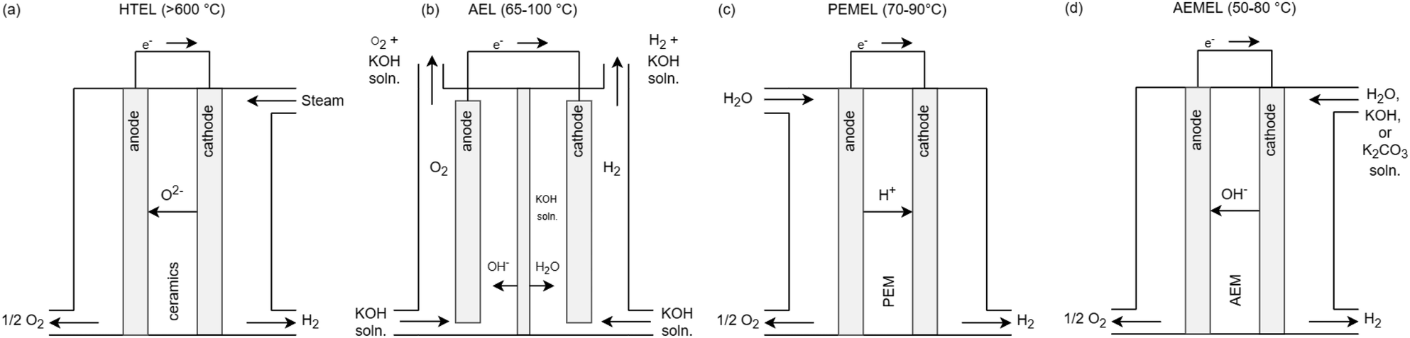 | ||
| Fig. 1 Schematic visualization of (a) HTEL, (b) AEL, (c) PEMEL and (d) AEMEL electrolysis cells with input and output streams as well as corresponding ion exchange adapted from ref. 8. | ||
If water is now added to the cell and electrical voltage is applied, the electrochemical splitting of water into hydrogen and oxygen begins.23 For this reaction, water (vaporous or liquid, or as a potassium hydroxide solution) flows continuously through the cells on the anode or cathode side. The gases produced are discharged on the respective side of the cell by the flow of the liquid or separately as a pure gas stream. The cells are stacked as repeating units to form a stack. Since the standard electrode potential between hydrogen and oxygen is +1.23 V and that of iron and hydrogen is just 0.361 V, the water must be free of metal ions, otherwise metals would accumulate at the anode from the water at an applied theoretical voltage of +1.23 V.23,24 Therefor the cells can only work with non-conductive water, this must be deionized in a process step beforehand. PEM cells are flushed with deionized water, as the solid polymer electrolyte can pick up foreign cationic species by simple contact with the solution.7 The product gas, which is led out of the stack, is either dissolved in KOH solution or is essentially a mixture of water vapor and hydrogen. In the AEL, the hydrogen is transported out of the cell with the KOH solution and then expelled in the gas/lye separator, depending on the applied technology. In the product gas of the PEMEL, water is also present in the hydrogen due to the electroosmotic drag, which draws water from the anode to the cathode side.7 In HTEL, part of the water vapor is present in the hydrogen product gas, since the water steam is never converted completely to hydrogen in the cell.25 In the next process step, the water is separated from the hydrogen and returned to the process.7 The same process step is carried out on the oxygen side. Since heat is generated during the electrochemical reaction, this heat is removed from the process by means of heat exchangers. This is done in the water recirculation to the stack. From this, a generic block flow diagram (BFD) to describe the generic process and required utilities can be created which is shown in Fig. 2. The BFD shows the necessary process blocks to operate the electrolysis.
 | ||
| Fig. 2 Generic block flow diagram (BFD) of an electrolysis system. | ||
Functional modularization can accelerate scale-up during the planning phase. Functional modularization is usually dissolved during the construction phase for cost reasons.26–30 For a scale-up the functional decomposition of the system into modules can be taken up again with a numbering-up of the functional modules according to ref. 12.
2.2 Introduction to modularization and module decomposition
Modular plants are described in VDI 277616 and are characterized by their defined sub-units, which can also be arranged hierarchically. By adding Process Equipment Assemblies (PEAs), modular plants can be easily adapted to changing boundary conditions. A PEA is a modular process unit that is mostly self-sufficient in terms of automation and safety and provides a process engineering step.16 Additionally, Functional Equipment Assemblies (FEAs) can be used for further adaption, which are designed as defined functional units of a PEA for different process or substance classes. Modularization can be applied in the planning and construction of process plants, which accelerates the planning process and ultimately the construction.31 This requires coordinated interfaces which should be easy and flexible to arrange.16 For adaptation, capacity is particularly relevant for the electrolysis plant context. As a result of the modular structure, three different approaches to scaling the capacity of a system emerge. These are sizing-up, equalizing-up and numbering-up.12 Sizing-up is a conventional enlargement to scale of characteristic dimensions of an equipment element (component of a PEA). Equaling-up represents the increase in the number of certain apparatus elements (component or PEA). Numbering-up is the increase of the number of whole functional apparatus environments or processes including periphery (PEA or module plant (MP)).8,12 Scaling can therefore be taken into account in the planning and construction of modular plants, particularly via the numbering-up of PEAs. A defined process is necessary for the planning and construction of a modular plant. This process is divided into the following steps:16
(1) Motivation analysis and determination of the degree of modularization.
(2) Identification of the essential process engineering process steps.
(3) Selection of Process Equipment Assemblies (PEAs), possible new development of PEAs.
(4) Configuration of PEAs by selection of Functional Equipment Assemblies (FEAs).
(5) Consideration and evaluation of the overall plant.
In the first step, the motivation for the functional modularization should be clarified. Likewise, a basic BFD of the system layouts should be created. Once this is done, the next step is to define all basic essential process steps or functions. In addition, material parameters are defined for the process engineering steps. Then the PEAs are selected by module manufacturers. If the PEAs for the required process engineering steps do not yet exist, they must be newly developed. Subsequently, the PEAs are configured with necessary functional adaptions via FEAs. If these are not available, they must also be developed. In the final step, the configured modular plant is viewed and evaluated according to selected evaluation criteria. If the evaluation criteria are not met, the planning process of the PEAs and FEAs must be repeated.16,32 The procedure presented here for planning a modular system is applied methodically in a modified form in the following: By creating a generic PFD, the system layout of the electrolysis system is given. Based on the system layout, it is identified which modules would be needed. The focus of the work shall be on the design or new development of modules for electrolysis systems. This procedure is applied once for each electrolysis technology: AEL, PEMEL and HTEL. Steps 1–4 according to VDI 2776 are shown as examples in sections 3.1 to 3.4. In order to initiate the process described, the following section starts with a motivation analysis.
3 Creation and evaluation of the generic module decomposition
3.1 Motivation analysis modularization
In the first step of module-based planning of electrolysis systems, the motivation analysis is carried out according to the mentioned steps of ref. 16. As mentioned in section 1, modularization shall support the scalability of electrolysis systems up to the gigawatt range. By creating repeatable PEAs, the modular electrolysis system is to be scaled by means of numbering-up. First approaches as well as requirements for modular electrolysis systems can be found in literature.8,283.2 Identification of essential process engineering steps
The first step of the motivation analysis is followed by the identification of essential process steps. The generic process for water electrolysis was described in Section 1. To create a generic process flow diagram (PFD) for AEL, PEMEL and HTEL, the literature was systematically searched for PFDs of these systems. In doing so, relevant PFDs were found in the 17 sources listed in Table 1.| AEL | PEMEL | HTEL |
|---|---|---|
| PFD33 | PFD33 | PFD33 |
| PFD2 | PFD34 | PFD2 |
| Model flowsheet35 | BFD36 | Schematic flow diagram of the considered HTEL based PtM system without explicit heat exchanger network37 |
| PFD38 | PFD38 | PFD38 |
| PFD39 | PFD: 5 MW and 100 MW schematic system layout14 | PFD: HTEL driven by solar tower energy40 |
| Schematic flow diagram41 | PFD: 5 MW and 100 MW schematic system layout39 | PFD42 |
| P&ID43 | PFD44 | PFD: HTEL in power to SNG process45 |
| PFD44 | PFD7 | PFD: rSOC system in a metanation process46 |
The PFDs found in literature were used to create generic PFDs of each electrolysis systems. For this purpose, the PFDs were evaluated and compared according to the included process engineering components and their interconnection. Commonalities were thereby included in the generic PFD considering the functionality of the resulting system. Subsequently, the generic PFDs were submitted to various electrolysis system manufacturers for evaluation and verification. As a result, generic flow diagrams of the respective electrolysis systems have now been agreed with the industry. In the second part of the industry survey, the generic flowsheets were divided into individual modules and again submitted to the electrolysis system manufacturers for evaluation and verification. BFDs for electrolysis systems can be found in the literature.47,48 From generic BFDs (see Fig. 2), the following essential process steps can be derived.
• Water treatment (deionization).
• Lye/water circulation (circulation).
• Electrochemical reaction (electrolysis).
• Current conversion (rectification).
• Temperature control (thermal regulation).
• Gas treatment (separation, drying and pressure boosting).
These essential process engineering steps are to be configured with PEAs in the next step. These PEAs can also be assigned to the categories according to ref. 11. Thus, water treatment is in pre-processing, circulation and electrochemical reaction in core electrolysis assemblies, power conversion and temperature control in utilities, and gas treatment in post-processing.
3.3 Selection of PEAs
After the identification of the essential process engineering steps follows the identification of PEAs. For this, first the description of the process-engineering boundary conditions as well as the design range is necessary. Care must be taken that the PEA has a high probability of repeatability in order to support the scaling of the performance of the overall system via numbering-up (parallel or series connection of PEAs). Another condition for a PEA is its integrated automation, implemented on a programmable logic controller or a microcontroller.32 In the analysis of the electrolysis systems from the literature, it will be reviewed which PEAs can be identified in conventional electrolysis systems AEL, PEMEL and HTEL. In the following points the generic PFDs of the different electrolysis technologies including the selection of PEAs are presented. Furthermore, a collection of electrolysis system data from different manufacturers is given, sorted by the respective electrolysis technology. This overview is important in order to gain an understanding of the existing electrolysis stackunit and system parameters, starting with the most technically mature technology with the highest TRL AEL, through the PEMEL to the HTEL.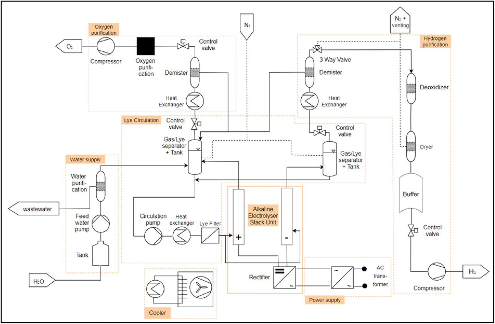 | ||
| Fig. 3 Module decomposition AEL, mixed lye circuit. | ||
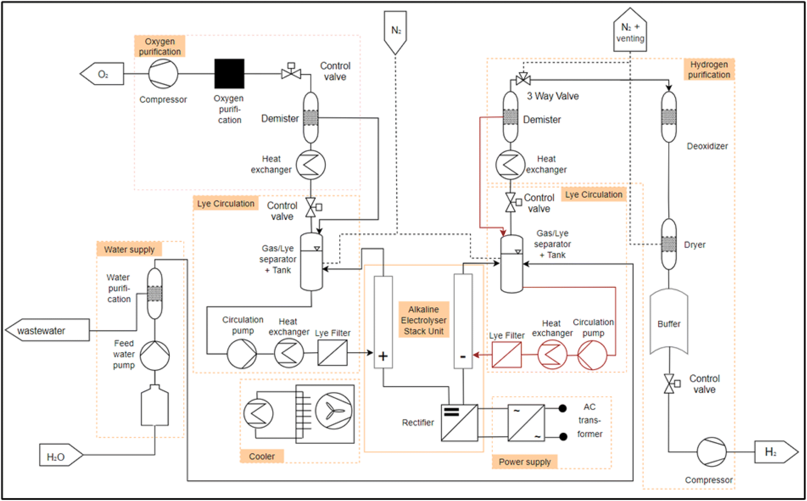 | ||
| Fig. 4 Module decomposition AEL, separated lye circuit. | ||
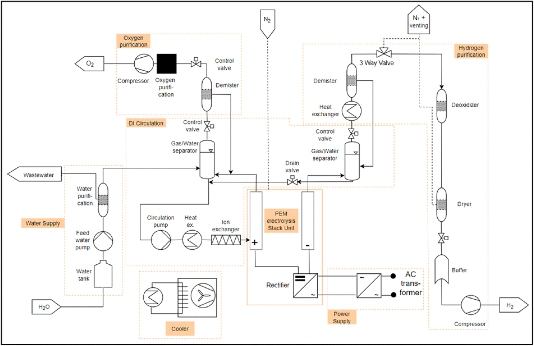
As described in the section 2.1, water is required for electrolysis. The water is temporarily stored in a storage tank and fed through a deionization system (e.g. a reverse osmosis or a mixed resin bed cartridge) via a pump. This is what we call “water supply” module. The deionized water is fed into the separator tank via pipes and mixed with the potassium hydroxide. From here, the aqueous alkaline solution is pumped through a heat exchanger to set the operating temperature and a fluid filter into the anode and cathode of the electrolysis “stack unit”. In the “stack unit”, the water is split into hydrogen and oxygen. The gases pass out of the “stack unit” with the lye solution. For the AEL, two separate module decompositions could be identified, for which the flow diagrams from Table 1 were analyzed. These differ with respect to the lye circuit. Fig. 3 shows a plant layout of the AEL with a mixed lye circuit. Here, the lye streams from the water and oxygen separator are combined and reintroduced into the electrolysis stack. Fig. 4 shows an AEL with separated lye circuits. The newly added components compared to 3 are shown in dark red in 4. The lye from the hydrogen separator and from the oxygen separator are treated separately and fed back to the cathode and the anode, respectively. The gases are now separated from the lye solution in the separator described above. After the hydrogen has been separated from the lye solution, it is cooled and passed through a dehumidifier. The subsequent three-way valve is used to inert the electrolysis system and to set the correct pressure in the separator tank, as the gas can be accumulated. The dried hydrogen is then passed through a residual oxygen destroyer to remove any remaining oxygen from the hydrogen, as the membrane of the stack unit is not completely impermeable to oxygen. The hydrogen is dried again and temporarily stored in a tank. The hydrogen can then be fed into a compressor via a control valve in order to set the correct pressure level for subsequent processes. The oxygen undergoes the same process steps on the anode side.
Considering the described general PFD for the AEL, the following PEAs are assumed for the operation of an electrolysis system:
• Water supply (water treatment).
• Water/lye circulation.
• Electrolysis stack with rectifier (stack unit).
• H2 purification.
• O2 purification.
• Power supply (transformator).
• Cooler (heat exchanger).
The individual modules (PEAs) in the module decomposition are indicated by an orange frame in Fig. 3 and 4. What is striking here is that in the existing systems, all modules can be operated autonomously, but there is a strong coupling between the electrolyte circuit and the gas–liquid separation. In all systems, the liquid tank for gas–liquid separation is also used as a buffer for the electrolyte. In theory, a separation of a “lye circulation” and a “hydrogen purification” module is exactly on the lye surface. This is due to the fact that a “lye circulation” module only works with a liquid and a “hydrogen purification” module works with a gas. The module boundary could therefore located on the fluid surface in the separator tank. This makes no sense for the definition of a PEA, as otherwise there would be two modules with an “open system border” and there would be a strong dependency between the two. This dependency must be resolved during the engineering of the plant. In order to have two completely independent modules, a gas/lye separator tank is assigned to a “lye circulation” module. This is equipped with a control valve at the gas outlet. This allows the interface between a “lye circulation” and “gas purification” modules to be clearly defined. The pressure on the anode or cathode side can be set within a “lye circulation” module via the control valve. If a “lye circulation” and “gas purification” modules were not designed separately, only one control valve would be required after the demister in the “gas purification”. This would result in a “lye circulation” module being dependent on a “gas conditioning” module. This is eliminated by a control valve in both modules. In this way, scaling is possible by numbering up the modules.
At this point, an interim conclusion can be made regarding the module decomposition of the AEL. The first step, a motivation analysis for the modularization of an electrolysis system, was shown in 3.1. The second step, a generic PFD based on the literature, was shown here and coordinated with industry partners by VDMA P2X4A. Furthermore, in the third step, the most important PEAs were identified and drawn into the generic PFDs 3 and 4. In step four of the general design procedure follows the configuration of a PEA with FEAs. As summary, for the AEL technology a minimum of 7 or 8 PEAs are identified. Out of these PEAs the multiple occurance of "gas separation", the "purification" and the "lye circulation" can potentially be fulfilled by identical PEAs. This can reduce the design efforts for the overall system, resulting in 6 different PEA-Types that would be needed.
In order to gain a better understanding of the performance of today's AEL stacks, various manufacturers of these stacks were examined and compared with each other. This is important to understand why scaling an electrolysis system into the gigawatt range is unlikely to succeed without a numbering-up, as the most powerful individual electrolysis stack in 2023 will have a capacity of 5 MW. To achieve a system output of one gigawatt, 200 of these stacks would be required. Numbering up without a modular system layout leads to high complexity and individual solutions with high efforts. Table 2 lists the manufacturers with the largest single stack, including the manufacturer data for the stacks that can be found in the data sheet. Individual stacks vary in their power classes. This ranges from 0.08 MWel to 5 MWel electrical connected load, which results in a hydrogen volume flow range of 15–4000 Nm3 h−1. However, there are differences regarding the purity of the hydrogen. The range of purity is given as 98–99.9998%.
| Unit | Sunfire | nel ASA | Thyssen-krupp nucera | Green hydrogen systems | McPhy | Cummins | John Cockerill | Stargate hydrogen | |
|---|---|---|---|---|---|---|---|---|---|
| Name of system | [—] | Hylink alkaline | A485 | 20 MW Module | HyProvide A90 | McLyzer 100–30 | HySTAT 15–10 | DQ1000 | Stellar series |
| Stackpower | [MW] | 5 | 5 (single stack) | 0.390–0.450 (BOL-EOL) | 0.5 | 0.08 | 5 | 0.460–0.535 (BOL-EOL) | |
| Stack rated voltage | [V] | 227–264 (BOL-EOL) | |||||||
| Stack rated current | [A] | 2027 | |||||||
| Mass flow | [kg h−1] | 8.1 | 89 | 8.96 | |||||
| Volume flow | [Nm3 h−1] | 1115 | 485 | 1000 | 90 | 100 | 15 | 1000 | 100 |
| H2 production range | [Nm3 h−1] | 300–485 | |||||||
| Turn down ratio | [%] | 20–100 | 15–100 | 10–100 | 40–100 | 40–100 | 55–100 | ||
| H2 pressure range | [bar g] | 30 | <200 (after compression) | 0,3 | 30 | 27 | 30 | 32 | |
| Operating temperature | [°C] | Up to 85 | 90 | 80–90 | |||||
| Energy consumption | [kW h NmH2−3] | 4.7 | 3.8–4.4 | 4.3 | 4.33 | 4.5 | 5.0–5.4 | 4.0–4.3 | 4.59 |
| [kW h kgH2−1] | 53.6 | 51.07 | |||||||
| System efficiency | [%] | 64 (LHV) | 84 (HHV) | 81.5 (HHV) | 77.2 (HHV)/65.2 (LHV) | ||||
| Purity | [%] | 99.6 | 99.99–99.998 | 99.95 | >99.998 | 99.998 | 99.8 | >98 | |
| System dimension | [m] | 2.1 × 1.3 × 2.416 | 6.9 × 2.2 × 2.2 | 20′ container | |||||
| System weight | [t] | <3.5 | 58 | ||||||
| Source | 49 | 50 | 51 | 52 | 53 and 54 | 55 | 56 | Values for “maximum efficiency”57 |
 | ||
| Fig. 5 Module decomposition for the PEMEL technology summarized from literature. | ||
The basic design of a PEMEL system is analogous to the system of the AEL from section 3.3.1. However, differences arise due to the different cell technologies. For example, the cell of the PEMEL is equipped with a solid polymer electrolyte, which substitutes a liquid electrolyte such as KOH or NaOH.41 Thus, the electrolyte circuit of the AEL is omitted and a DI water circuit is installed, whereas the main difference between the two circuits are the media properties, the general function stays the same. Another difference to the AEL is that the water feed only takes place on the anode side, as shown in Fig. 5. Like the AEL, the water supply and the gas purification line remain on the anode side in order to separate oxygen from the DI water in the PEMEL and the electrolyte in the AEL, including the demister and pressure control valve. The separator on the cathode side is different because there is no water circuit on the cathode side. Water is only brought to the cathode via an electro-osmotic drag, which is why the separator is much smaller than in the AEL. The cooler for condensing water and the pressure control valve on the cathode side remain unchanged.7
For the PEMEL, there were also 7 PEAs identified. Again, the purification can potentially be build identically. Furthermore, water supply and DI circulation for the PEMEL can be designed identically for the AEL.
Table 3 summarizes the data from PEM system manufacturers from the data sheets. PEM electrolysis systems range from connected electrical power of 0.707 MWel to 2.5 MWel. This power range results in a hydrogen output range of 264–1062 kg d−1. They are thus smaller than AEL electrolysis systems (AEL: 0.08–5 MWel). The actual data of the found manufacturers are summarized in Table 3.
| Unit | Siemens energy | H-TEC systems/MAN ES | Nel ASA | Cummins | ITM power | Plug power | Hoeller electrolyzer GmbH | Hystar | |
|---|---|---|---|---|---|---|---|---|---|
| Name of system | [—] | Silyzer 300 (single stack) | ME450/1400 | MC500 | HyLYZER 500-30 | HGAS1SP | EX-425D | Prometheus L | Mira 300 |
| Stack power | [MW] | 0.73 | 1 | 2.5 | 2.5 | 0.707 | 1.4 | 1.4 | |
| Mass flow | [kg d−1] | 100–2000 kg h−1 (system) | 450 | 1062 | 11 kg h−1/(264 kg d−1) | 425 | 635 | 28.2 kg h−1 | |
| Volume flow | [Nm3 h−1] | 210 | 492 | 500 | 200 | 295 | 314 | ||
| H2 production range | [Nm3 h−1] | 42–210 | |||||||
| Turn down ratio | [%] | 5–100 | 20–100 | 10–100 | 5–100 | 15–100 | |||
| Ramp rate | [%/s] | 10 | −100 to 100 | ||||||
| Rampup (min.-Nom.) | [s] | 10 | 30 | 15 | <30 | <10 | |||
| Startup (off-nom.) | [min] | 8 | 5 | <5 | |||||
| H2 pressure range | [bar g] | 15–30 | 30 | 20 | <40 | 4 | |||
| Energy consumption | [kW h NmH2−3] | 4.8 | 4.5 | 5.1 | 4.9 | ||||
| [kW h kgH2−1] | 50.4 | 49.9 | 54.2 | ||||||
| System efficiency | [%] | >75.5 | 74 | ||||||
| Purity | [%] | 99.999 | 99.999 | 99.998 | 99.999 | 99.97 | |||
| System dimension | [m] | 13.4 × 4.0 × 5.7 | 12.2 × 2.5 × 3 | 40′ container | 29.3 m2 | 0.60 × 0.48 | 40′ container | ||
| System weight | [t] | 36 | 24 (with power supply) | ||||||
| Source | 39, 58 and 59 | 60 | 61 | 55 | 62 | 63 | 64 | 65 |
 | ||
| Fig. 6 Module decomposition HTEL. | ||
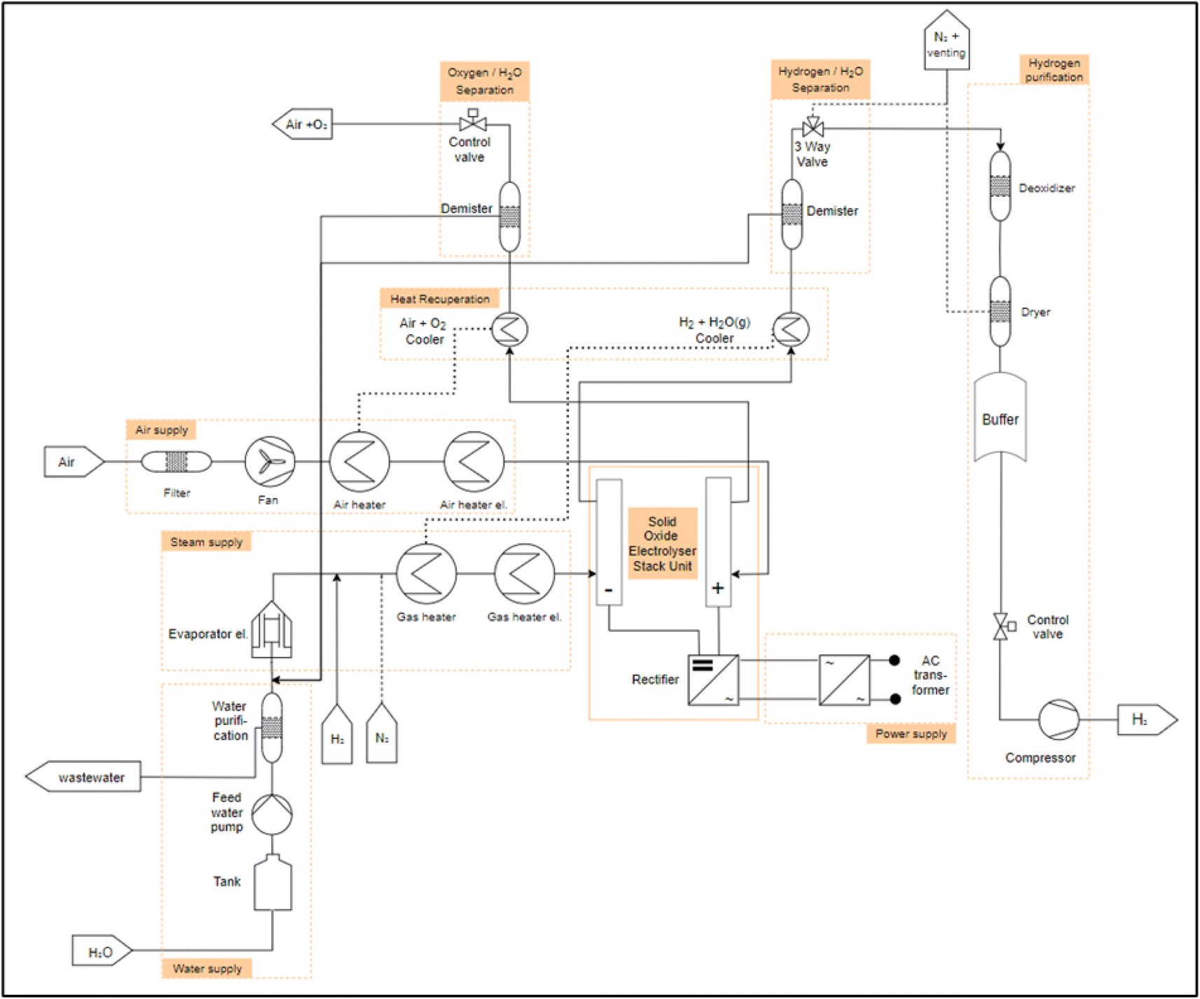
The HTEL can be separated into 9 PEAs. The separation can probably be designed identically for both gas streams. In contrast to AEL and PEMEL, there is no need for circulation since the educts are gaseous. Instead, a steam generation unit is needed. The water supply unit can be build identically to PEMEL and AEL (Fig. 6).
High temperature electrolysis systems is currently offered commercially by five manufacturers and is in a power range from 2.86 MW to 100 MW (Table 4). There are still some manufacturers in the field of SOFC (solid oxide fuel cell) that could produce a HTEL, since the fuel cell as well as the electrolysis process can be operated with the same cell, which was already demonstrated by Sunfire in 2017 in a rSOC (reversible solid oxide cell).66,67 Fuel cell energy also cites the reversibility of the SOC (solid oxide cell) as an advantage of the technology over other.68 For example, HEXIS has already announced that it will develop an HTEL system.69 The stacks are manufactured by mPower. Ceres power is also an SOFC system supplier in collaboration with Robert Bosch GmbH.70 Robert Bosch GmbH manufactures a 10 kWel fuel cell system.71 Furthermore, Ceres power has already announced that it will manufacture an HTEL system with a production capacity of 600 kg of hydrogen per day.72 Elcogen and E&KOA are stack manufacturers that sell only an electrolysis stack, without a system. Already in August 2020, the two companies decided to collaborate to produce a commercial SOFC system. In this case, the SOFC was manufactured by elcogen and assembled into a stack by E&KOA. P&P Energytech integrates this stack into a 10 kW fuel cell system.73
| Unit | Sunfire | Haldor Topsoe | Bloom energy | Fuel cell energy | Elcogen | |
|---|---|---|---|---|---|---|
| Name of system | [—] | Hylink SOEC | ElcoStack E3000 | |||
| Type | [—] | System | System | System | System | Single stack |
| Power | [MW] | 2.86 | 100 | 3 kW | ||
| Actice cell area | [cm2] | 14399 |
||||
| Mass flow | [kg d−1] | 226.8 kg h−1 | 600 | |||
| Volume flow | [Nm3 h−1] | 750 | 32000 |
|||
| Turn down ratio | [%] | 5–100 | 10–100 | 5–100 | 0–100 | |
| Rampup (min.-Nom.) | [min] | 10 | 10 | |||
| Ramprate | [%/min] | 10 | ||||
| Steam Covertion ratio | [%] | |||||
| H2 pressure range | [bar g] | 2 | 1 | |||
| Energy consumption | [kW h NmH2−3] | 3.6 | 3.1 | |||
| [kW h kgH2−1] | 46 | 39.4–43.8 | ||||
| System efficiency | [%] | 84 (LHV) | 90–100 (HHV) | |||
| Purity | [%] | 99.99 | 99.999 | 99.99 | 99 | |
| Source | 74 | 75 | 76 | 77 | 78 |
3.4 System manufacturers and global distribution
For this work, performance data from different electrolysis system manufacturers was researched and compared. The location of the headquarters of the manufacturers was also determined. Fig. 7 shows the manufacturers of commercially available electrolysis systems according to the location of their headquarters in the world and the electrolysis process they use.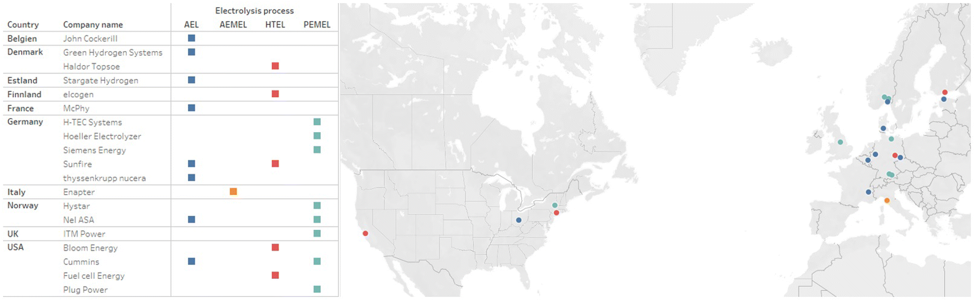 | ||
| Fig. 7 Comparison of the manufacturers to the electrolysis process with the Country of Headquarter. | ||
To localize the found literature and data sheets, the manufacturers are concentrated in the European region and the USA. Most manufacturers have their expertise in one of the electrolysis processes described in this paper. Only Sunfire, Nel ASA and Cummins have two technologies each available in their portfolio. In addition to the three technologies presented, Anion Exchange Membrane electrolysis (AEMEL) should be mentioned here. This is currently being manufactured by Enapter in a 2.4 kW units79 and also as system with a capacity of 1 MW.80 A system called “AEM Flex 120” is also offered, in which 10 stack units are connected in one line. 5 of these strings are interconnected to form a complete system.81 Additionally to Enapter, Sunfire is also planning to enter the research and development of the AEMEL, as published in a press release,82 which would make Sunfire a manufacturer providing three technologies. Other companies were found during the research in Europe and North America, but they have not published a proper data sheet as of December 2023. One such company is Battolyser from the Netherlands, which couples a battery with an AEL System.83 Hydrogen pro ASA from Norway also provide a 5 MW stack, as can also be seen in a press report from 7 November 2023.84 Verdagy in California, USA, also produces an AEL system which was demonstrated at a pilot plant.85 Even though only manufacturers from Europe and North America were compared, Asian companies found during the research should also be mentioned for the purpose of completeness. SUNGROW,86 LONGi87 and AUYAN88 should be mentioned here for the production of AEL stacks. SUNGROW89 also offers a PEMEL stack.
4 Generic balancing of an alkaline electrolysis system
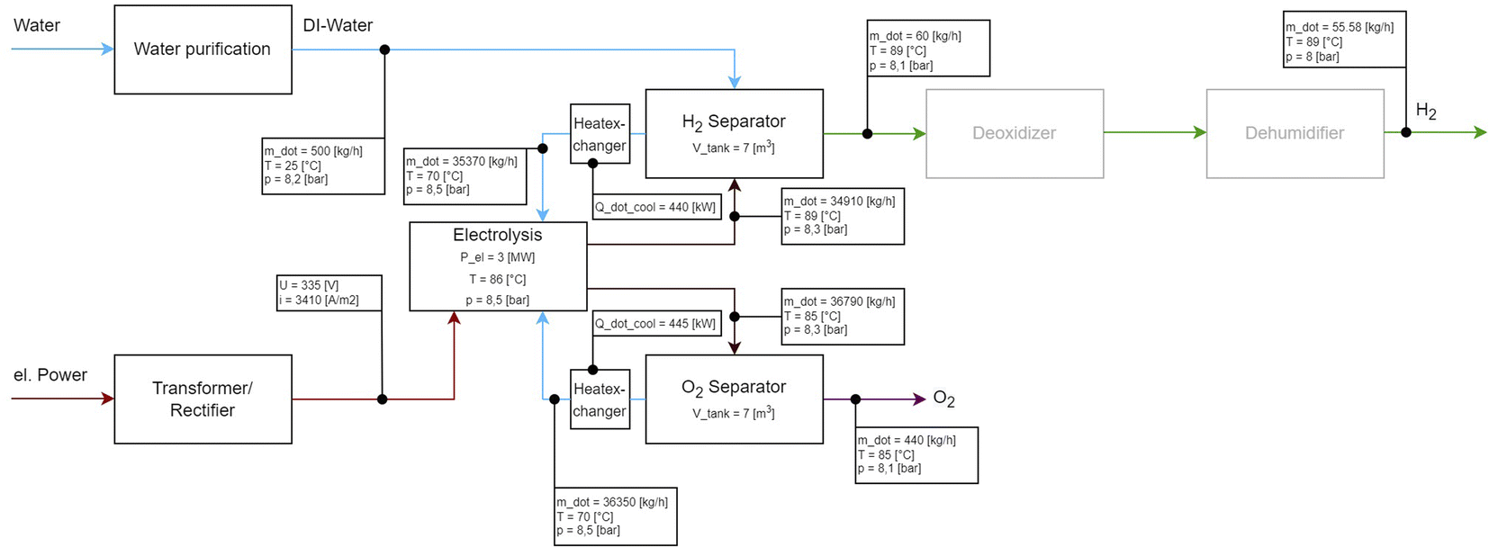
In the following, an alkaline electrolysis stack will be generically designed, to show how the identified modules could be balanced. The largest available alkaline electrolysis stack was used for this purpose. The power was set to a stationary 3 MW and the incoming and outgoing volume flows were calculated. The polarization curve was taken from the literature.90 Mass, chemical component and energy balances were developed using literature.91,92 Thermophysical properties for lye are from ref. 93 thermophysical properties of pure components (H2O, H2, O2) calculated from available information in ref. 94. The basic correlations between the current applied to the cell and the resulting hydrogen volume flow can be found in ref. 2 and 8. The underlying general system layout is shown in Fig. 2 and is shown as a general BFD with the respective applied volume flows for the deionized water, hydrogen, oxygen and the individual lye circuits. The system layout with two separate lye circuits was selected, as described in sec. 3.3.1 (Fig. 4). The incoming voltage and current are also shown. A 3 MW stack with 163 cells is assumed,90 which is operated at an efficiency of 60.87% (LHV)/73.01% (HHV) at a temperature of 86 °C and a pressure of 8.5 bar. The energy consumption is 4.93 kW h NmH2−3. The input voltage and current can be determined from the polarisation curve. These are 335 V DC with a current density of 3410 A m−2. With this configuration, 60 kg h−1 of hydrogen can be produced. This requires 500 kg h−1 of deionised water. From the selected stack unit, a volume flow of 34910 kg h−1 of lye mixture with dissolved H2 enters the H2 separator at a temperature of 89 °C and a pressure of 8.3 bar. The gas separation efficiency in the H2 separator is assumed to be 1, which means that all gas is separated from the lye solution.90 At an operating pressure of up to 20 bar, the gas–lye separator is designed with a length-to-diameter ratio of 3:1.95 Assuming a volume of 7 m3, this corresponds to a length of approx. 4.31 m and a diameter of 1.43 m. A lye mixture of 35370 kg h−1 is pumped out of the separator and fed into a heat exchanger. This cools the volume flow down to 70 °C. The pressure downstream of the heat exchanger is 8.5 bar. This transfers 0.44 MW of heat, which is available for another process. After the lye mixture has been cooled, it is fed back into the stack. 60 kg h−1 of hydrogen is separated from the separator at a temperature of 89 °C and a pressure of 8.1 bar. The oxygen is separated from the lye circulation in the same way as the hydrogen. This operation produces 440 kg h−1 of oxygen at a temperature of 85 °C at a pressure of 8.1 bar. If this generic model is compared with the values of the stack manufacturers from Table 2, it can be seen that the values for the energy consumption and efficiency match those of the manufacturers. There are now many approaches to optimising this generic approach to alkaline electrolysis. One approach would be to increase the conductivity of the alkaline mixture by increasing the temperature. Approaches can be found here.96,97 Another is to increase efficiency by using suitable control strategies and adapting the system design of the heat exchangers.98 In addition, there is the optimisation of the cell and stack design as well as the optimisation of the materials used in both, which can be found here.99–102
5 Summery and conclusions
In the first part of the publication, a detailed process for the creation of the module decomposition was presented. The workload here focuses primarily in the detailed literature research on the P&IDs and PFDs. After the correlations were worked out, they were coordinated with the industry network of the VDMA e.V. Power-to-X for Applications. Furthermore, the resulting generic PFDs were divided into individual PEAs. Subsequently, manufacturers offering a commercially available electrolysis system were selected and compared with regard to their performance data. Since there is currently no uniform standardization for performance data for electrolysis systems, the manufacturers provide performance data in different units. An attempt was made to put these into context and to contrast or compare them. For the AEL, with its very mature technology level, there are now a large number of manufacturers in Europe and North America. Eight different manufacturers were compared. The sizes range from 0.08–5 MW single stacks, which is a large range of different outputs. It is noticeable that the energy consumption of the individual stacks of the different manufacturers does not differ much with 3.8–5.4 kW h kgH2−1. This may be a sign of the maturity of the technology in all performance classes. It should be noted that some manufacturers provide information on the beginning of life (BOL) and some on the end of life (EOL). Likewise, some manufacturers base their stated efficiency on the lower or higher heating value. A uniform specification of the values seems to make sense here. In PEMEL technology, the eight different manufacturers compared also give different values. Often the specific energy consumption is given with reference to the produced volume of hydrogen, often with reference to the produced mass. In the power classes, the individual manufacturers do not differ as much as with the AEL. The specified stack power ranges from 0.707–2.5 MW. Also the energy consumption is with 4.5–5.1 kW h mH2−3 closer to each other than with the AEL technology. A uniform specification would also be useful here. The fewest commercial manufacturers in Europe and North America were found in HTEL technology. Information on individual stacks was only found at elogen, all other manufacturers only state the performance of their corresponding complete systems. It can be assumed that several stacks are used in a system to achieve the system power. The power ranges from 3 kW of a single stack up to 100 MW of a complete system. The AEMEL stack from Enapter with 2.4 kW stack power is in the power range of the HTEL stack from elogen. In addition, a system design for a 5 MW alkaline electrolysis system was carried out using static simulation and some values from the simulation were compared with the information provided by the stack manufacturers.Another result of this work are the generic process flow diagram of a modular electrolysis system. It can be seen that modules such as “water supply” occur in all systems and can be used for the combination of different technologies in one electrolysis systems. The modules “Lye/DI circulation” can be found for the AEL and PEMEL. Here a practical approach for modularization can be found, since the "Lye/DI circulation" is closely coupled with the electrolysis stacks from a process engineering perspective, since this module sets all process parameters for the electrolysis stack, such as the lye/DI pressure, temperature and the correct lye/DI volume flow. In addition, the product gas pressure is set via this module. The circulation modules of the AEL and PEMEL do not have the same dimensions due to the size of the stacks, but the process itself is identical. This can be a requirement for the same automation of the modules. A subsequent compression of the hydrogen is also provided in all processes. This is mostly due to the process operation of the electrolysis process at near-atmospheric pressures. Increasing the pressure of the hydrogen is essential for most downstream processes. For this purpose, further investigations on the module decomposition have to be performed.
6 Outlook
In further work, the module decomposition should be applied to a real use case and should be examined. For this chosen use case, a modularized electrolysis system could be configured once and the process control strategies for a stack unit could be implemented as well. A first approach to this can be found in ref. 103. As mentioned, the next step should be to evaluate the configured overall system for the specific usecase. To perform this evaluation, it would be useful to identify evaluation criteria specifically for electrolysis plants. One approach for evaluation criteria in the field of modular systems comes from the process industry.104 Here, evaluation criteria were defined for the four different categories “costs”, “flexibility”, “process engineering” and “time-to-process”, which were weighted by experts from the process industry. Furthermore, the application of modularization to the operation of the electrolysis system should be investigated. A first approach can be found in ref. 105. Another approach to this can be the different process control strategies from ref. 8 which were further developed and applied in a first model in ref. 106. The use of different electrolysis technologies in one electrolysis system is also conceivable with modularization to leverage further potential in flexibility and efficiency. In addition, approaches to modularization are being investigated in a learning factory called P2O-Lab.107Author contributions
Hannes Lange: conceptualization, methodology, validation, investigation, writing–original draft, writing–review & editing, visualization. Anselm Klose: conceptualization, writing–review & editing, supervision, project administration. Daniel Erdmann: conceptualization, resources, investigation. Lucien Beisswenger: conceptualization, resources, investigation. Leon Urbas: writing–review & editing, supervision, project administration, funding acquisition.Conflicts of interest
There are no conflicts to declare.Acknowledgements
We would like to thank the German Federal Ministry of Education and Research and the project management organization Jülich for their financial support within the framework of the eModule research project (FKZ 03HY116A) of the H2Giga lead platform. Furthermore, the P2O-Lab of TUD Dresden University of Technology is thanked for its support.References
- C. Hebling, M. Ragwitz, T. Fleiter, U. Groos, D. Härle, A. Held and et al., Eine Wasserstoff-Roadmap für Deutschland, 2019, p. 51 Search PubMed.
- A. Buttler and H. Spliethoff, Current status of water electrolysis for energy storage, grid balancing and sector coupling via power-to-gas and power-to-liquids: A review, Renewable and Sustainable Energy Reviews, 2018, 82, 2440–2454 CrossRef CAS . Available from: https://linkinghub.elsevier.com/retrieve/pii/S136403211731242X.
- Die Nationale Wasserstoffstrategie. 2020;Available from: https://www.bmbf.de/bmbf/shareddocs/downloads/files/die-nationale-wasserstoffstrategie.pdf?__blob=publicationFile%26v=1 Search PubMed.
- K. Purr, J. Günther, H. Lehmann and P. Nuss. Climate change 36/2019: Wege in eine ressourcenschonende Treibhausgasneutralität - Rescue Studie. Umweltbundesamt, 2019, p. 444 Search PubMed.
- D. R. D. BfGuR. B. DERA, Mineralische Rohstoffe für die Wasserelektrolyse. Update ed , Deutsche Rohstoffagentur, Berlin, 2022. OCLC: 1350848290. Available from: https://www.deutsche-rohstoffagentur.de/DERA/DE/Downloads/DERA/heft-01-22.pdf;jsessionid=CEF4AF826D5E40112BEA2B4A96D3ED40.1_cid331?__blob=publicationFile%26v=2 Search PubMed.
- Bundesministerium für Wirtschaft und Energie, Die fortschreibung der nationalen Wasserstoffstrategie, 2023, Available from: https://www.bmbf.de/SharedDocs/Downloads/de/2023/230726-fortschreibung-nws.pdf?__blob=publicationFile%26v=1 Search PubMed.
- D. Bessarabov, H. Wang, H. Li and N. Zhao. PEM Electrolysis for Hydrogen Production, 2016 Search PubMed.
- H. Lange, A. Klose, W. Lippmann and L. Urbas, Technical evaluation of the flexibility of water electrolysis systems to increase energy flexibility: A review, Int. J. Hydrogen Energy, 2023, 48(42), 15771–15783 CrossRef CAS . Available from: https://linkinghub.elsevier.com/retrieve/pii/S0360319923000459.
- T. Terlouw, C. Bauer, R. McKenna and M. Mazzotti, Large-scale hydrogen production via water electrolysis: a techno-economic and environmental assessment, Energy Environ. Sci., 2022, 15(9), 3583–3602 RSC . Available from: http://xlink.rsc.org/?DOI=D2EE01023B.
- Y. Wang, Y. Pang, H. Xu, A. Martinez and K. S. Chen, PEM Fuel cell and electrolysis cell technologies and hydrogen infrastructure development – a review, Energy Environ. Sci., 2022, 15(6), 2288–2328 RSC . Available from: http://xlink.rsc.org/?DOI=D2EE00790H.
- L. Bittorf, L. Beisswenger, D. Erdmann, J. Lorenz, A. Klose, H. Lange and et al., Upcoming domains for the MTP and an evaluation of its usability for electrolysis. In: 2022 IEEE 27th International Conference on Emerging Technologies and Factory Automation (ETFA), 2022, pp. 1–4 Search PubMed.
- S. Lier, S. Paul, D. Ferdinand and M. Grünewald, Modulare Verfahrenstechnik: Apparateentwicklung für wandlungsfähige Produktionssysteme, Chem. Ing. Tech., 2016, 88(10), 1444–1454 CrossRef CAS . Available from: https://onlinelibrary.wiley.com/doi/10.1002/cite.201600015.
- A. Reitze, N. Jürgensmeyer, S. Lier, M. Kohnke, J. Riese and M. Grünewald, Roadmap for a Smart Factory: A Modular, Intelligent Concept for the Production of Specialty Chemicals, Angew. Chem., Int. Ed., 2018, 57(16), 4242–4247 CrossRef CAS PubMed . Available from: https://onlinelibrary.wiley.com/doi/abs/10.1002/anie.201711571.
- DLR. DZfLuReV, LBST LBSG ISE FIfSE KBBUTG, Studie über die Planung einer Demonstrationsanlage zur Wasserstoff-Kraftstoffgewinnung durch Elektrolyse mit Zwischenspeicherung in Salzkavernen unter Druck. 2014, Available from: https://elib.dlr.de/94979/1/2014_DLR_ISE_KBB_LBST_PlanDelyKaD.pdf Search PubMed.
- B. Flamm, C. Peter, F. N. Büchi and J. Lygeros, Electrolyzer modeling and real-time control for optimized production of hydrogen gas, Appl. Energy, 2021, 281, 116031 CrossRef CAS . Available from: https://linkinghub.elsevier.com/retrieve/pii/S0306261920314690.
- VDI, Process engineering plants - Modular plants - Fundamentals and planning modular plants - Part 1 (VDI 2776-1:2020), Beuth Verlag, 2020 Search PubMed.
- VDI/VDE/NAMUR, Automation Engineering of modular systems in the process industry - General concept and interfaces - Part 1 (VDI/VDE/NAMUR 2658-1:2022-01), Beuth Verlag, 2022 Search PubMed.
- H. Bloch, A. Fay and M. Hoernicke, Analysis of service-oriented architecture approaches suitable for modular process automation, In 2016 IEEE 21st International Conference on Emerging Technologies and Factory Automation (ETFA), IEEE, Berlin, Germany, 2016. pp. 1–8. Available from: http://ieeexplore.ieee.org/document/7733651/ Search PubMed.
- H. Bloch, A. Fay, T. Knohl, M. Hoernicke, J. Bernshausen, S. Hensel and et al., A microservice-based architecture approach for the automation of modular process plants, In 2017 22nd IEEE International Conference on Emerging Technologies and Factory Automation (ETFA). Limassol, IEEE, 2017. pp. 1–8. Available from: http://ieeexplore.ieee.org/document/8247573/ Search PubMed.
- A. Klose, S. Merkelbach, A. Menschner, S. Hensel, S. Heinze and L. Bittorf, et al., Orchestration Requirements for Modular Process Plants in Chemical and Pharmaceutical Industries, Chem. Eng. Technol., 2019, 42(11), 2282–2291 CrossRef CAS . Available from: https://doi.org/10.1002/ceat.201900298.
- A. Stutz, A. Fay, M. Barth and M. Maurmaier, Orchestration vs. Choreography Functional Association for Future Automation Systems, IFAC-PapersOnLine., 2020, 53(2), 8268–8275 CrossRef . Available from: https://www.sciencedirect.com/science/article/pii/S2405896320325891.
- A. Klose, J. Lorenz, L. Bittorf, K. Stark, M. Hoernicke and A. Stutz, et al., Orchestration of modular plants: Procedure and application for orchestration engineering, atp magazin, 2022, 63(9), 68–77 CrossRef . Available from: https://ojs.di-verlag.de/index.php/atp_edition/article/view/2599.
- J. Dohmann, Experimentelle Einführung in die Elektrochemie: Grundlagen - Konzepte - Theorie, Springer Berlin Heidelberg, Berlin, Heidelberg, 2020. Available from: http://link.springer.com/10.1007/978-3-662-59763-7 Search PubMed.
- CRC Handbook of Chemistry and Physics: a Ready-Reference Book of Chemical and Physical Data, CRC Press, Boca Raton, 2014. OCLC: 1082348969 Search PubMed.
- J. Schefold, A. Brisse, A. Surrey and C. Walter, 80,000 current on/off cycles in a one year long steam electrolysis test with a solid oxide cell, Int. J. Hydrogen Energy, 2020, 45(8), 5143–5154 CrossRef CAS . Available from: https://linkinghub.elsevier.com/retrieve/pii/S0360319919319809.
- J. Rottke, F. Grote, H. Fröhlich, D. Köster and J. Strube, Efficient Engineering by Modularization into Package Units, Chem. Ing. Tech., 2012, 885–889 CrossRef CAS . Available from: http://doi.wiley.com/10.1002/cite.201200029.
- N. Krasberg, L. Hohmann, T. Bieringer, C. Bramsiepe and N. Kockmann, Selection of Technical Reactor Equipment for Modular, Continuous Small-Scale Plants, Processes, 2014, 2(1), 265–292 CrossRef CAS . Available from: http://www.mdpi.com/2227-9717/2/1/265.
- T. Seifert, H. Schreider, S. Sievers, G. Schembecker and C. Bramsiepe, Real option framework for equipment wise expansion of modular plants applied to the design of a continuous multiproduct plant, Chem. Eng. Res. Des., 2015, 93, 511–521 CrossRef CAS . Available from: https://linkinghub.elsevier.com/retrieve/pii/S0263876214003384.
- H. Radatz, J. M. Elischewski, M. Heitmann, G. Schembecker and C. Bramsiepe, Design of equipment modules for flexibility, Chem. Eng. Sci., 2017, 168, 271–288 CrossRef CAS . Available from: https://linkinghub.elsevier.com/retrieve/pii/S0009250917302683.
- H. Radatz, M. Schröder, C. Becker, C. Bramsiepe and G. Schembecker, Selection of equipment modules for a flexible modular production plant by a multi-objective evolutionary algorithm, Comput. Chem. Eng., 2019, 123, 196–221 CrossRef CAS . Available from: https://linkinghub.elsevier.com/retrieve/pii/S0098135418307166.
- S. Sievers, T. Seifert, M. Franzen, G. Schembecker and C. Bramsiepe, Lead time estimation for modular production plants, Chem. Eng. Res. Des., 2017, 128, 96–106 CrossRef CAS . Available from: https://linkinghub.elsevier.com/retrieve/pii/S0263876217305579.
- 2776-2:2022 V, Verfahrenstechnische Anlagen - Modulare Anlagen - Design Modularer Anlagen, VDI, 2022 Search PubMed.
- T. Smolinka, E. T. Ojong and J. Garche, Hydrogen Production from Renewable Energies—Electrolyzer Technologies, in Electrochemical Energy Storage for Renewable Sources and Grid Balancing, Elsevier, 2015, pp. 103–128, Available from: https://linkinghub.elsevier.com/retrieve/pii/B9780444626165000085 Search PubMed.
- S. A. Grigoriev, V. N. Fateev, D. G. Bessarabov and P. Millet, Current status, research trends, and challenges in water electrolysis science and technology, Int. J. Hydrogen Energy, 2020, 45(49), 26036–26058 CrossRef CAS . Available from: https://linkinghub.elsevier.com/retrieve/pii/S0360319920310715.
- P. Haug, B. Kreitz, M. Koj and T. Turek, Process modelling of an alkaline water electrolyzer, Int. J. Hydrogen Energy, 2017, 42(24), 15689–15707 CrossRef CAS . Available from: https://linkinghub.elsevier.com/retrieve/pii/S0360319917318633.
- B. Yodwong, D. Guilbert, M. Phattanasak, W. Kaewmanee, M. Hinaje and G. Vitale, Proton Exchange Membrane Electrolyzer Modeling for Power Electronics Control: A Short Review, Journal of Carbon Research, 2020, 6(2), 29 CrossRef CAS . Available from: https://www.mdpi.com/2311-5629/6/2/29.
- L. Wang, M. Pérez-Fortes, H. Madi, S. Diethelm, J. V. herle and F. Maréchal, Optimal design of solid-oxide electrolyzer based power-to-methane systems: A comprehensive comparison between steam electrolysis and co-electrolysis, Appl. Energy, 2018, 211, 1060–1079 CrossRef CAS . Available from: https://linkinghub.elsevier.com/retrieve/pii/S0306261917316367.
- Green hydrogen cost reduction: Scaling up electrolysers to meet the 1.5C climate goal, ed. I. IRENA, International Renewable Energy Agency, Abu Dhabi, 2020 Search PubMed.
- M. Holst, S. Aschbrenner, T. Smolinka, C. Voglstätter and G. Grimm, Cost Forecast for Low-Temperature Electrolysis - Technology Driven Bottom-Up Prognosis for PEM and Alkaline Water Electrolysis Systems, Fraunhofer Institute for Solar Energy Systems ISE, 2021,p. 79 Search PubMed.
- A. Mohammadi and M. Mehrpooya, A comprehensive review on coupling different types of electrolyzer to renewable energy sources, Energy, 2018, 158, 632–655 CrossRef CAS . Available from: https://linkinghub.elsevier.com/retrieve/pii/S0360544218311381.
- J. Brauns and T. Turek, Alkaline Water Electrolysis Powered by Renewable Energy: A Review, Processes, 2020, 8(2), 248 CrossRef CAS . Available from: https://www.mdpi.com/2227-9717/8/2/248.
- J. Aicart, Z. Wuillemin, B. Gervasoni, D. Reynaud, F. Waeber and C. Beetschen, et al., Performance evaluation of a 4-stack solid oxide module in electrolysis mode, Int. J. Hydrogen Energy, 2022, 47(6), 3568–3579 CrossRef CAS . Available from: https://linkinghub.elsevier.com/retrieve/pii/S0360319921044360.
- J. Brauns, J. Schönebeck, M. R. Kraglund, D. Aili, J. Hnát and J. Žitka, et al., Evaluation of Diaphragms and Membranes as Separators for Alkaline Water Electrolysis, J. Electrochem. Soc., 2021, 168(1), 014510 CrossRef CAS . Available from: https://iopscience.iop.org/article/10.1149/1945-7111/abda57.
- Y. Guo, G. Li, J. Zhou and Y. Liu, Comparison between hydrogen production by alkaline water electrolysis and hydrogen production by PEM electrolysis, IOP Conf. Ser. Earth Environ. Sci., 2019, 371(4), 042022 CrossRef . Available from: https://iopscience.iop.org/article/10.1088/1755-1315/371/4/042022.
- M. De Saint Jean, P. Baurens, C. Bouallou and K. Couturier, Economic assessment of a power-to-substitute-natural-gas process including high-temperature steam electrolysis, Int. J. Hydrogen Energy, 2015, 40(20), 6487–6500 CrossRef CAS . Available from: https://linkinghub.elsevier.com/retrieve/pii/S0360319915006655.
- P. Mottaghizadeh, S. Santhanam, M. P. Heddrich, K. A. Friedrich and F. Rinaldi, Process modeling of a reversible solid oxide cell (r-SOC) energy storage system utilizing commercially available SOC reactor, Energy Convers. Manage., 2017, 142, 477–493 CrossRef CAS . Available from: https://linkinghub.elsevier.com/retrieve/pii/S0196890417302121.
- G. Harp, Technologien zur Produktion von Wasserstoff für die Herstellung synthetischer Kraftstoffe. In Zukünftige Kraftstoffe, ed. W. Maus, Springer Berlin Heidelberg, Berlin, 2019. pp. 305–370, Available from: http://link.springer.com/10.1007/978-3-662-58006-6_15 Search PubMed.
- A. K. Sarker, A. K. Azad, M. G. Rasul and A. T. Doppalapudi, Prospect of Green Hydrogen Generation from Hybrid Renewable Energy Sources: A Review, Energies, 2023, 16(3), 1556 CrossRef CAS . Available from: https://www.mdpi.com/1996-1073/16/3/1556.
- Sunfire-Hylink Alkaline, 2021, Available from: https://www.sunfire.de/files/sunfire/images/content/Sunfire.de-Sunfire-Factsheet-HyLink-Alkaline.pdf Search PubMed.
- nel ASA. Nel Hydrogen Electrolyseres PD-0600-0125 Rev D, 2021, Available from: https://nelhydrogen.com/wp-content/uploads/2020/03/Electrolysers-Brochure-Rev-D.pdf Search PubMed.
- thyssenkrupp Nucera, Large-scale water electrolysis for green hydrogen production, 2023, Available from: https://thyssenkrupp-nucera.com/wp-content/uploads/2022/11/thyssenkrupp-nucera-green-hydrogen-solutions-brochure.pdf.
- HyProvide A-Series v1.5, 2021, Available from: https://greenhydrogen.dk/wp-content/uploads/2021/02/A-Series-brochure-1-20421.pdf Search PubMed.
- McLyzer, 2020, Available from: https://cellar-c2.services.clever-cloud.com/com-mcphy/uploads/2020/08/2-0.05.McPhy_Portfolio_ELY_McLyzer_EN.pdf Search PubMed.
- C. Braatz, Elektrolyseanlagen für Multi-MW Anwendungen, 2019. Available from: https://windenergietage.de/2019/wp-content/uploads/sites/4/2019/11/28WT05_F23_1805_McPhy_20191104.pdf Search PubMed.
- D. Thomas, Power to Hydrogen to Power Solution - Cummins, 2020. Available from: https://etn.global/wp-content/uploads/2020/11/Webinar-FLEXnCONFU_Cummins_D_Thomas.pdf Search PubMed.
- J. Cockerill, DQ1000 Alkaline Electrolyser, 2023, Available from: https://hydrogen.johncockerill.com/wp-content/uploads/sites/3/2023/04/dq-1000-def-2-hd-en.pdf Search PubMed.
- Sepc Sheet - Stellar Series, 2023, Available from: https://stargatehydrogen.com/alkaline-electrolyser-stacks/#contact-us Search PubMed.
- Silyzer 300 the Next Paradigm of PEM Electrolysis, 2020, Available from: https://assets.siemens-energy.com/siemens/assets/api/uuid:a193b68f-7ab4-4536-abe2-c23e01d0b526/datasheet-silyzer300.pdf Search PubMed.
- E. Wolf and R. Saliger. Herausforderungen für Windparkbetreiber und Chancen durch Power to Gas. Forum 16, 28 Windenergietage, 2019 Nov;Available from: https://windenergietage.de/2019/wp-content/uploads/sites/4/2020/01/28WT06_F16_1450_Wind_Wasserstoff_Siemens.pdf Search PubMed.
- Systems HT. H-TEC SYSTEMS PEM Electrolyser ME450/1400, 2022, Available from: https://www.h-tec.com/produkte/detail/h-tec-pem-elektrolyseur-me450/me450/ Search PubMed.
- nel ASA. M Series Containerized - Proton Exchange Membrane (PEM) hydrogen generation system, 2021, Available from: https://nelhydrogen.com/wp-content/uploads/2022/06/M-Series-Containerized-Spec-Sheet-Rev-E.pdf Search PubMed.
- ITM Power - HGAS1SP, 2023, Available from: https://itm-power.com/products/hgas1sp Search PubMed.
- Plug EX-425D, 2023, Available from: https://www.plugpower.com/wp-content/uploads/2022/04/EX-<?pdb_no 425D?>425D<?pdb END?>_042522.pdf.
- GmbH HE, Hoeller Prometeus, 2023, Available from: https://www.hoeller-electrolyzer.com/entwicklungsziele.html Search PubMed.
- ASH, Hystar's technical specifications, 2023, Available from: https://hystar.com/wp-content/uploads/2022/09/TechnicalSpecification_for_website.pdf Search PubMed.
- K. Schwarze, O. Posdziech, S. Kroop, N. Lapeña-Rey and J. Mermelstein, Green Industrial Hydrogen via Reversible High-Temperature Electrolysis, ECS Trans., 2017, 78(1), 2943–2952 CrossRef CAS . Available from: https://iopscience.iop.org/article/10.1149/07801.2943ecst.
- K. Schwarze, O. Posdziech, J. Mermelstein and S. Kroop, Operational Results of an 150/30 kW RSOC System in an Industrial Environment, Fuel Cells, 2019, 19(4), 374–380 CrossRef CAS .Available from: https://onlinelibrary.wiley.com/doi/abs/10.1002/fuce.201800194.
- T. Leo, S. Jolly, J. Nevius, J. Gombas and J. Juopperi, White Paper: Reducing the Cost of Hydrogen Production - Fundamentals of High-Temperature, High-Efficiency Solid Oxide Electrolysis, 2022, Available from: https://go.fuelcellenergy.com/hubfs/Solided1-472c-a772-b4ff5ccd218e Search PubMed.
- Products in Pipeline, 2023, Available from: http://www.hexis.ch/applications.html Search PubMed.
- Collaborating for impact: Bosch - Hydrogen-ready technology for a net zero future, 2021, Available from: https://wp-ceres-2022.s3.eu-west-2.amazonaws.com/media/2022/08/CPL003_Hydrogen-ready-technology-for-a-net-zero-future.pdf Search PubMed.
- GmbH RB, BOSCH Energy-efficient. Decentralized. H2-ready. With fuel cell systems by Bosch, 2022, Available from: https://www.bosch-sofc.com/media/en/ueber_uns/faq/sofc-product-brochure .pdf Search PubMed.
- SOEC Technology Programme, 2023, Available from: https://www.ceres.tech/technology/ceres-hydrogen/soec-technology-programme/ Search PubMed.
- elcogen Elcogen, E&KOA and P&P Energytech Sign Collaboration Agreement to Commercialize SOFC System, 2020, Available from: https://elcogen.com/elcogen-ekoa-and-pp-energytech-sign-collaboration-agreement-to-commercialize-sofc-system/ Search PubMed.
- SUNFIRE-HYLINK SOEC, 2021, Available from: https://www.sunfire.de/files/sunfire/images/content/Sunfire.de-Sunfire-Factsheet-HyLink-SOEC-20210303.pdf Search PubMed.
- SOEC High-Temperature Electrolysis 0341.2021/Rev.2, 2021, Available from: https://www.topsoe.com/hubfs/DOWNLOADS/DOWNLOADS-Brochures/SOEC-high-temperature-electrolysis-factsheet.pdf?hsCtaTracking=dc9b7bfd-4709-4e7e-acb5-39e76e956078%7C20d976e0-d884-4c00-9fcf-3af3d0850476 Search PubMed.
- Bloom Energy - Bloom Electrolyzer, 2022, Available from: https://www.bloomenergy.com/wp-content/uploads/Data-Sheet_Bloom-Electrolyzer-10-MW_UPDATED-6.24.22.pdf Search PubMed.
- Solid Oxide Electrolyzer - Soec, 2022, Available from: https://go.fuelcellenergy.com/hubfs/Solid-Oxide-Electrolyzer-Spec-Sheet.pdf Search PubMed.
- Elcogen. elcoStack E3000, 2022, Available from: https://elcogen.com/wp-content/uploads/2022/12/Elcogen_tooteleht_A4bleed_72dpi_2022.pdf Search PubMed.
- AEM Electrolyser EL 4.0, 2022, Available from: https://handbook.enapter.com/electrolyser/el40/downloads/Enapter_Datasheet_EL40_EN.pdf Search PubMed.
- Enapter Enapter AEM Multicore, 2022, Available from: https://www.enapter.com/app/uploads/2022/10/Enapter-AEM-Multicore%E2%84%A2-Datasheet-EN.pdf Search PubMed.
- AEM Flex 120, 2023, Available from: https://handbook.enapter.com/electrolyser/aem-flex120/downloads/Enapter_Datasheet_AEM-Flex-120_EN.pdf Search PubMed.
- GmbHS, Press Release - Hydrogen Innovation: Sunfire And Fraunhofer Ifam Launch Project To Scale Aem Technology For Industrial Applications, 2023, Available from: https://www.sunfire.de/en/news/detail/hydrogen-innovation-sunfire-und-fraunhofer-ifam-launch-project-to-scale-aem-technology-for-industrial-applications Search PubMed.
- Systems B, Product Sheet Battolyser® 500, 2023, Available from: https://static1.squarespace.com/static/64fef941e025ce1df5184285/t/652961a01d7b10502aadfbc9/1697210792173/Battolyser+500+product+sheet.pdf Search PubMed.
- pro H. HydrogenPro ASA – Third quarter 2023 results, 2023, Available from: https://hydrogen-pro.com/2023/11/07/confirming-100mw-order-andritz/ Search PubMed.
- Verdagy, eDynamic Electrolyser Hydrogen Power Plant, 2023, Available from: https://static1.squarespace.com/static/64fef941e025ce1df5184285/t/652961a01d7b10502aadfbc9/1697210792173/Battolyser+500+product+sheet.pdf Search PubMed.
- SUNGROW, ALK Water Electrolysis Equipment, 2023, Available from: https://info-support.sungrowpower.com/application/pdf/2023/05/18/ALK-water-electrolyser.pdf Search PubMed.
- LONGi. LHy-A1000, 2023, Available from: https://www.longi.com/en/products/hydrogen/lhy-a1000/ Search PubMed.
- AUYAN. Alkaline Electrolysis Water Hydrogen Production Electrolyzer; 2023. Available from: https://www.auyangloble.com/hydrogen-production/Hydrogen-Production-Electrolyzer.html Search PubMed.
- SUNGROW. PEM water electrolysis equipment; 2023, Available from: https://info-support.sungrowpower.com/application/pdf/2023/05/18/PEM-water-electrolyser.pdf Search PubMed.
- G. Sakas, A. Ibáñez-Rioja, V. Ruuskanen, A. Kosonen, J. Ahola and O. Bergmann, Dynamic energy and mass balance model for an industrial alkaline water electrolyzer plant process, Int. J. Hydrogen Energy, 2022, 47(7), 4328–4345 CrossRef CAS . Available from: https://linkinghub.elsevier.com/retrieve/pii/S0360319921045110.
- R. Tesser and V. Russo, Advanced Reactor Modeling with MATLAB: Case Studies with Solved Examples, De Gruyter, 2020, Available from: https://www.degruyter.com/document/doi/10.1515/9783110632927/html Search PubMed.
- P. Haug, M. Koj and T. Turek, Influence of process conditions on gas purity in alkaline water electrolysis, Int. J. Hydrogen Energy, 2017, 42(15), 9406–9418 CrossRef CAS . Available from: https://linkinghub.elsevier.com/retrieve/pii/S0360319916336588.
- D. Le Bideau, P. Mandin, M. Benbouzid, M. Kim and M. Sellier, Review of necessary thermophysical properties and their sensivities with temperature and electrolyte mass fractions for alkaline water electrolysis multiphysics modelling, Int. J. Hydrogen Energy, 2019, 44(10), 4553–4569 CrossRef CAS . Available from: https://linkinghub.elsevier.com/retrieve/pii/S0360319919300175.
- VDI eV, VDI-wärmeatlas, Springer Vieweg Berlin, Heidelberg, 11th edn, 2013, pp. 2512–5281 Search PubMed.
- G. P. Towler and R. K. Sinnott, Chemical Engineering Design: Principles, Practice, and Economics of Plant and Process Design, Butterworth-Heinemann, Boston, MA, 2nd edn, 2013 Search PubMed.
- K. Stewart, L. Lair, B. De La Torre,N. L. Phan, R. Das,D. Gonzalez and et al., Modeling and Optimization of an Alkaline Water Electrolysis for Hydrogen Production, In: 2021 IEEE Green Energy and Smart Systems Conference (IGESSC), IEEE, Long Beach, CA, USA, 2021. pp. 1–6. Available from: https://ieeexplore.ieee.org/document/9618679/ Search PubMed.
- D. Jang, H. S. Cho, S. Lee, M. Park, S. Kim and H. Park, et al., Investigation of the operation characteristics and optimization of an alkaline water electrolysis system at high temperature and a high current density, J. Cleaner Prod., 2023, 424, 138862 CrossRef CAS . Available from: https://linkinghub.elsevier.com/retrieve/pii/S0959652623030202.
- X. Shen, X. Zhang, H. Lv, G. Li and T. T. Lie, Structure design and control strategy of a new alkaline water electrolyzer based on heat exchange, Int. J. Energy Res., 2019, 43(9), 4729–4742 CrossRef CAS . Available from: https://onlinelibrary.wiley.com/doi/abs/10.1002/er.4612.
- D. Le Bideau, O. Chocron, P. Mandin, P. Kiener, M. Benbouzid and M. Sellier, et al., Evolutionary Design Optimization of an Alkaline Water Electrolysis Cell for Hydrogen Production, Appl. Sci., 2020, 10(23), 8425 CrossRef CAS . Available from: https://www.mdpi.com/2076-3417/10/23/8425.
- K. Zouhri and S. Lee, Evaluation and optimization of the alkaline water electrolysis ohmic polarization: Exergy study, Int. J. Hydrogen Energy, 2016, 41(18), 7253–7263 CrossRef CAS . Available from: https://linkinghub.elsevier.com/retrieve/pii/S0360319916305638.
- R. Qi, M. Becker, J. Brauns, T. Turek, J. Lin and Y. Song, Channel design optimization of alkaline electrolysis stacks considering the trade-off between current efficiency and pressure drop, J. Power Sources, 2023, 579, 233222 CrossRef CAS . Available from: https://linkinghub.elsevier.com/retrieve/pii/S0378775323005980.
- H. Lv, J. Chen, W. Zhou, X. Shen and C. Zhang, Mechanism analyses and optimization strategies for performance improvement in low-temperature water electrolysis systems via the perspective of mass transfer: A review, Renewable Sustainable Energy Rev., 2023, 183, 113394 CrossRef CAS . Available from: https://linkinghub.elsevier.com/retrieve/pii/S1364032123002514.
- M. Mock, H. Lange, I. Viedt, K. R. Gopa, J. Mädler and L. Urbas, Dynamic operation for the effective use of green hydrogen in Power-to-X value chains, In 33rd European Symposium on Computer Aided Process Engineering, ed. A. C. Kokossis, M. C. Georgiadis and E. Pistikopoulos. Elsevier; 2023, vol. 52, pp. 1267–1272. ISSN: 1570-7946. Available from: https://www.sciencedirect.com/science/article/pii/B978044315274050202X Search PubMed.
- P. Schindel, W. Harding and G. Stenger, et al., General approach for technology and Process Equipment Assembly (PEA) selection in process design, Chem. Eng. Process., 2021, 159, 108223 CrossRef . Available from: https://linkinghub.elsevier.com/retrieve/pii/S0255270120306851.
- C. Schirmer, Bewertung von Modularisierungsansätzen für Elektrolyseanlagen. 2022 Search PubMed.
- J. Lorenz, A. Klose, H. Lange, T. Kock and L. Urbas, Flexible Process Control for Scalable Electrolysis Systems, in III. International Conference on Electrical, Computer and Energy Technologies (ICECET 2023), IEEE, Cape Town-South Africa, 2023, pp. 1–6, doi: DOI:10.1109/ICECET58911.2023.10389401.
- L. Vogt, F. Pelzer, A. Klose, V. Khaydarov, H. Lange, I. Viedt and et al., P2O-Lab: A Learning Factory for Digitalization and Modularization, In: Proceedings of the Conference on Learning Factories (CLF) 2023, Reutlingen: SSRN, 2023. Available from: https://ssrn.com/abstract=4456423 Search PubMed.
| This journal is © The Royal Society of Chemistry 2024 |