
 Open Access Article
 This Open Access Article is licensed under a Creative Commons Attribution-Non Commercial 3.0 Unported Licence
A covalent organic framework as a dual-active-center cathode for a high-performance aqueous zinc-ion battery†
Hongbao
Li‡
,
Mengge
Cao‡
,
Zhenli
Fu‡
,
Quanwei
Ma
,
Longhai
Zhang
,
Rui
Wang
,
Fei
Liang
,
Tengfei
Zhou
 and
Chaofeng
Zhang
*
and
Chaofeng
Zhang
*
Institutes of Physical Science and Information Technology, Leibniz International Joint Research Center of Materials Sciences of Anhui Province, Anhui Province Key Laboratory of Environment-Friendly Polymer Materials, Key Laboratory of Structure and Functional Regulation of Hybrid Material (Ministry of Education), Anhui University, Hefei 230601, China. E-mail: cfz@ahu.edu.cn
First published on 27th January 2024
Abstract
Organic electrode materials have shown significant potential for aqueous Zn ion batteries (AZIBs) due to their flexible structure designability and cost advantage. However, sluggish ionic diffusion, high solubility, and low capacities limit their practical application. Here, we designed a covalent organic framework (TA-PTO-COF) generated by covalently bonding tris(4-formylbiphenyl)amine (TA) and 2,7-diaminopyrene-4,5,9,10-tetraone (PTO-NH2). The highly conjugated skeleton inside enhances its electron delocalization and intermolecular interaction, leading to high electronic conductivity and limited solubility. The open channel within the TA-PTO-COF provides ionic diffusion pathways for fast reaction kinetics. In addition, the abundant active sites (C![[double bond, length as m-dash]](https://www.rsc.org/images/entities/char_e001.gif) N and CO) endow the TA-PTO-COF with a large reversible capacity. As a result, the well-designed TA-PTO-COF cathode delivers exceptional capacity (255 mA h g−1 at 0.1 A g−1), excellent cycling stability, and a superior rate capacity of 186 mA h g−1 at 10 A g−1. Additionally, the co-insertion mechanism of Zn2+/H+ within the TA-PTO-COF cathode is revealed in depth by ex situ spectroscopy. This study presents an effective strategy for developing high-performance organic cathodes for advanced AZIBs.
N and CO) endow the TA-PTO-COF with a large reversible capacity. As a result, the well-designed TA-PTO-COF cathode delivers exceptional capacity (255 mA h g−1 at 0.1 A g−1), excellent cycling stability, and a superior rate capacity of 186 mA h g−1 at 10 A g−1. Additionally, the co-insertion mechanism of Zn2+/H+ within the TA-PTO-COF cathode is revealed in depth by ex situ spectroscopy. This study presents an effective strategy for developing high-performance organic cathodes for advanced AZIBs.
Introduction
The exploration of advanced and eco-friendly electrochemical energy storage systems was prompted by the energy crisis and environmental pollution.1–5 One of the most promising candidates for next-generation large-scale energy storage is rechargeable aqueous metal-ion batteries, which feature high safety, low cost, and environmental friendliness.6–10 Different from organic solvent-based electrolytes, aqueous electrolytes possess high ionic conductivity, low toxicity, and non-flammability.11,12 Among them, AZIBs are desirable energy storage devices due to the inherent merits of affordable and non-toxic zinc, which is found in high abundance in nature (300 times higher than lithium), possesses a low redox potential of −0.76 V and has a large theoretical capacity of 820 mA h g−1.13–17 Up to now, various inorganic cathode materials have been explored to achieve high energy densities and good stability, such as manganese-based and vanadium-based materials, and Prussian blue analogues.18–20 However, they suffer from poor cycling performance owing to their dissolution in acidic electrolyte, and their structure variation during repeating charge/discharge processes. Furthermore, the scarcity of transition metal elements will result in high cost and impede the large-scale application of AZIBs.21Organic compounds are composed primarily of naturally occurring elements, including C, H, N, O, and S elements. These compounds possess many advantages in terms of low cost, structural diversity, design flexibility, and meeting the requirements for sustainable development.1,8,22,23 Importantly, the structural diversity of organic compounds contributes to easy tailoring of their electrochemical performance on the molecular level, leading to a large number of new types of organic cathodes.24–29 In addition, the unique reaction mechanism and flexible structure of organic compounds can avoid large structural changes and enhance the mobility of large-sized Zn ions, which is vital for the operation of high-performance AZIBs.30 To date, many organic electrodes have been discovered, such as conductive polymers, organosulfur compounds, and nitroxide radical and carbonyl group-containing compounds.27,31,32 In particular, carbonyl compounds have achieved significant success as cathodes for rechargeable metal-ion batteries.33 However, the high solubility and low conductivity of small organic molecules greatly restrict their cyclability and rate performance. To solve these problems, salification, hybridization, and polymerization have been adopted. However, the introduced inactive composition and dense structure of the polymer will inevitably lead to reduced capacity and low ionic conductivity.25 Therefore, it is essential and challenging to design carbonyl compounds with high ionic/electronic conductivity, multiple electroactive centers, and excellent chemical/physical stability.34
Covalent organic frameworks (COFs) are a class of porous crystalline organic materials constructed from covalently linked and periodically arranged organic molecules.35–37 Benefitting from their highly cross-linked frameworks, robust covalent bond, and strong π–π stacking interactions, COFs exhibit stable chemical and physical characteristics and are resistant to solubility problems in organic electrolytes.38,39 Notably, unlike the dense structure of polymers, the open pore channels in the COFs provide sufficient diffusion pathways for metal ions to access the active sites inside, thereby resulting in high active site utilization.40 Additionally, the redox-active units within the COFs can be precisely manipulated at the molecular level, resulting in a large capacity.41 COFs are promising electrode materials for rechargeable AZIBs due to their unique properties. However, most of the COF electrodes contain only a single active redox group, which inevitably leads to a low theoretical and practical capacity.42,43
Herein, we designed and synthesized a covalent organic framework (TA-PTO-COF) with the dual redox-active sites of CO and CN via bonding tris(4-formylbiphenyl)amine (TA) and 2,7-diaminopyrene-4,5,9,10-tetraone (PTO-NH2). The conjugated structure, multiple active sites (CN and CO groups) and regular channels endowed TA-PTO-COF with high conductivity, plentiful exposed active sites, and fast ion diffusion pathways, resulting in rapid reaction kinetics and large capacity. In addition, the large molecular structure, robust covalent framework, and conjugated structure-induced π–π stacking inhibit solubility in the electrolyte and improve the structural stability. TA-PTO-COF as a cathode material showed a high discharge capacity of 255 mA h g−1 at 0.1 A g−1, exceptional rate performance (186 mA h g−1 at 10 A g−1) and long-term cyclability (1000 cycles at 1 A g−1). Importantly, the Zn2+/H+ co-insertion behavior within TA-PTO-COF was confirmed in detail through ex situ measurements. This study presents an organic cathode material for AZIBs and offers new insights into the development of COFs for the next generation of batteries.44
Experimental section
Synthesis of monomeric pyrene-4,5,9,10-tetrone (PTO)
First, a solution of pyrene (4.0 g) was prepared by dissolving it in a mixture of dichloromethane (140 mL) and acetonitrile (140 mL) in a round-bottom flask. After the pyrene was completely dissolved, the mixture of 70.0 g of sodium periodate and 200 mL of deionized water was stirred at 35 °C for 10 h after adding 1.0 g of ruthenium(III) chloride hydrate. After the reaction, the black-green precipitate was removed by filtration and washed repeatedly with a large amount of dichloromethane to remove any remaining impurities. The yellow filtrate was extracted with dichloromethane to eliminate any residual small amount of black-green suspension, and finally, the resulting yellow organic solution was purified using column chromatography to remove by-products and obtain an orange product. The yield of PTO was 23.2%. 1H NMR (400 MHz, DMSO-d6, 298 K), δ 8.33 (d, J = 7.7 Hz, 4H), 7.74 (t, J = 7.7 Hz, 2H).Synthesis of 2,7-dinitropyrene-4,5,9,10-tetrone (PTO-NO2)
PTO (4.73 mmol, 1.24 g) was added to a mixture of sulfuric acid and nitric acid (4![[thin space (1/6-em)]](https://www.rsc.org/images/entities/char_2009.gif) :1 by volume) and the solution was then refluxed at 90 °C for 4 h. Following the reaction, the mixture was poured into 200 mL of deionized water. The mixture was then filtered multiple times with saturated sodium bicarbonate and water. The resulting yellow precipitate was collected and dried under vacuum at 65 °C for 24 h, yielding 1.32 g of yellow PTO-NO2 in 75% yield. 1H NMR (400 MHz, DMSO-d6, 298 K), δ 8.89 (d, J = 7.7 Hz, 4H).
:1 by volume) and the solution was then refluxed at 90 °C for 4 h. Following the reaction, the mixture was poured into 200 mL of deionized water. The mixture was then filtered multiple times with saturated sodium bicarbonate and water. The resulting yellow precipitate was collected and dried under vacuum at 65 °C for 24 h, yielding 1.32 g of yellow PTO-NO2 in 75% yield. 1H NMR (400 MHz, DMSO-d6, 298 K), δ 8.89 (d, J = 7.7 Hz, 4H).
Synthesis of 2,7-diaminopyrene-4,5,9,10-tetraone (PTO-NH2)
PTO-NO2 (2 mmol, 704 mg) and Na2S 9H2O (24 mmol, 5.76 g) were first added to 60 mL DMF, and the mixture was reacted at 80 °C for 10 h under an argon atmosphere. Then, the product was poured into 100 mL of ethyl acetate, and the sample was filtered and washed with methanol and water, and then dried under vacuum at 65 °C for 24 h, resulting in a purple-black powder. The crude product was further purified by dispersing it in 20 mL of carbon disulfide and then heating it in an oven to yield black PTO-NH2 weighing 314 mg (70% yield). 1H NMR (400 MHz, DMSO-d6, 298 K), δ 7.37 (d, J = 7.7 Hz, 2H), 5.96 (t, J = 7.7 Hz, 2H).Synthesis of TA-PTO-COF
PTO-NH2 (21.9 mg, 0.075 mmol) and tris(4-formylbiphenyl)amine (TA) (10.5 mg, 0.05 mmol) were added to a Schlenk tube, followed by the addition of 0.9 mL of homo-trimethylbenzene, 0.3 mL 1,4-dioxane and 0.1 mL acetic acid. The tube was subsequently subjected to frozen degassing 3 times under an argon atmosphere, and at 120 °C for 3 days. Finally, the black powder of TA-PTO-COF (29 mg, 87%) was obtained by filtering, washing to separate, and drying.Material characterization
The chemical composition and structure of TA-PTO-COF were identified by Fourier transform infrared spectroscopy (FT-IR, Vertex80+-Hyperion 2000), X-ray photoelectron spectroscopy (XPS, Axis Ultra DLD Kratos AXIS SUPRA), and powder X-ray diffractometry (PXRD, Bruker D8 Advance, Germany). The morphology was observed by scanning electron microscopy (SEM, Regulus 8230). Thermal stability was studied by thermogravimetric analysis (TGA, TG 209 F3 Tarsus) under nitrogen atmosphere.Electrochemical measurements
The working electrodes were composed of active materials, Ketjen black, and PVDF in a mass ratio of 6:3:1. The mass loading of the corresponding active components of the electrode was about 1.0–1.1 mg cm−2. TA-PTO-COF, zinc foil, and 2 M ZnSO4 were used as the cathode, anode, and electrolyte, respectively. The amount of electrolyte (2 M ZnSO4) is 50 μL. The electrochemical performance of the assembled batteries was evaluated on NEWARE equipment and a CHI 760E electrochemical workstation.
Theoretical calculations
The structure of TA-PTO-COF was constructed and optimized at the B3LYP/6-31+G (p) level. Then the repeated unit was selected and reoptimized at the same level. The corresponding highest occupied molecular orbitals (HOMO), the lowest unoccupied molecular orbitals (LUMO), and the electron density distribution were determined using the Multiwfn 3.8 program. The Gaussian 16 software package was used for all theoretical calculations.45Results and discussion
The synthesis of the PTO-NH2 precursor is displayed in Scheme S1,† and the product of each step was confirmed by 1H NMR (Fig. S1–S3†). TA-PTO-COF was synthesized through a Schiff-based reaction between TA and PTO-NH2. The electrolyte soaked with TA-PTO-COF is almost colorless, indicating the low solubility of TA-PTO-COF in the electrolyte (Fig. 1a). Additionally, further analysis of the UV-vis spectrum was conducted to confirm the solubility of TA-PTO-COF in electrolytes (Fig. S4†). It is evident that the presence of TA-PTO-COF in the electrolyte produces a spectrum similar to that of the bare electrolyte, providing further confirmation of its insolubility. Density functional theory (DFT) calculations were applied to understand the electrochemical properties of TA-PTO-COF. As shown in Fig. 1b, the frontier molecular orbital calculations included the highest occupied molecular orbital (HOMO) and the lowest unoccupied molecular orbital (LUMO). TA-PTO-COF shows a low LUMO energy, which contributes to enhancing the charge delocalization. The narrow energy gap (ΔE) of 1.85 eV between the HOMO and LUMO of TA-PTO-COF indicates efficient electron conduction with low energy barriers, which facilitates better charge transfer and redox reaction.40 The molecular electrostatic potential (MESP) was used to study the electronic structure and further elucidate the active sites of TA-PTO-COF. As shown in Fig. 1c, the positive MESP region is represented by the red region, which is the nucleophilic center, while the electrophilic center is represented by the blue region (negative MESP region).46 The electronegativity of the TA-PTO-COF molecules is concentrated in the blue region surrounding the CN and CO groups, revealing the electrochemically active sites for storing the cations (such as Zn2+ and H+). The PXRD pattern of TA-PTO-COF exhibits high crystallinity and typical peaks located at 6.50° and 28.62°, which correspond to the (110) and (001) planes, respectively, indicating the presence of a crystalline framework structure (Fig. 1d). Among them, the (001) plane is mainly attributed to the π–π stacking between the layers of TA-PTO-COF,47 indicating a multilayered COF structure. The crystal structure of TA-PTO-COF was confirmed by transmission electron microscopy (TEM) and revealed that the lattice strip spacing of TA-PTO-COF is 0.348 nm, corresponding to the (001) facets (Fig. 1e).38Fig. 1f demonstrates that TA-PTO-COF possesses a pore structure (the area outlined in white), while Fig. 1g illustrates its typical mesoporous nature with a pore diameter of about 45 Å.
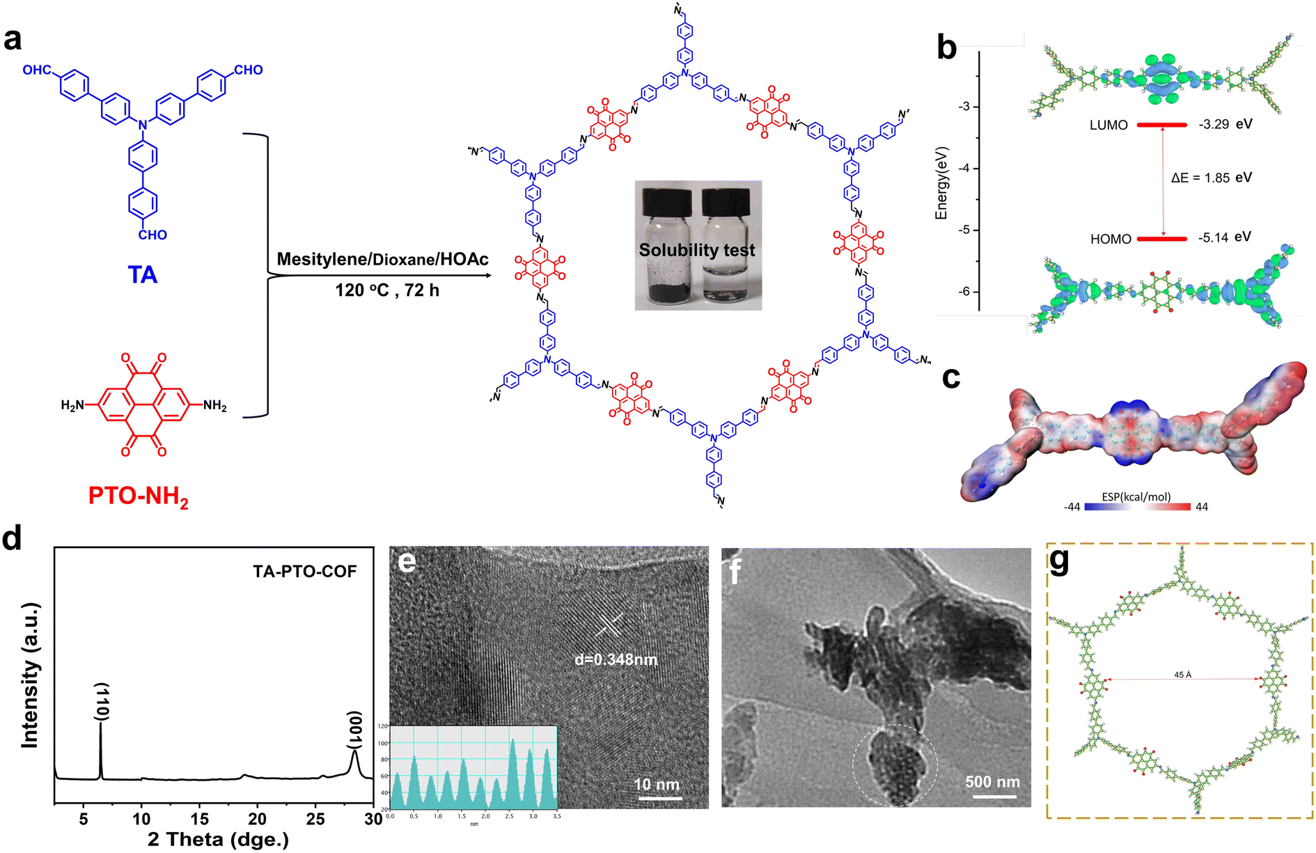 | ||
| Fig. 1 (a) Illustration of the synthetic route for TA-PTO-COF. (b) Calculated frontier molecular orbital energy. (c) Calculated MESP distribution of TA-PTO-COF. (d) PXRD pattern of the TA-PTO-COF. (e and f) TEM images of TA-PTO-COF. (g) Calculated aperture size of TA-PTO-COF. | ||
The chemical structure features of TA-PTO-COF were also investigated. Fig. 2a shows the Fourier transform infrared spectra (FT-IR) of PTO-NH2, TA, and TA-PTO-COF. Compared with the PTO-NH2 monomer, TA-PTO-COF shows a weaker –NH2 stretching vibration peak around 3500–3000 cm−1, indicating the presence of residual –NH2 groups at the edge of TA-PTO-COF. The peak at 3078 cm−1 corresponds to the C–H stretching vibration peak, and the peaks at 1673 and 1275 cm−1 are assigned to the CO and C–N bonds, respectively.48 Specifically, a peak at 1452 cm−1 emerges in the COF, which is primarily attributed to the vibration of CN. These results prove the successful preparation of TA-PTO-COF. Additionally, the chemical composition of TA-PTO-COF was demonstrated by X-ray photoelectron spectroscopy (XPS). The survey spectra confirmed the presence of C, N, and O elements in TA-PTO-COF (Fig. 2b). As shown in Fig. 2c, the C 1s spectra at 287.5 eV, 284.8 eV, 286.41 eV, and 285.5 eV correspond to CO, C–C/CC, CN, and C–N bonds, respectively. It should be noted that the π–π* peak at 291.3 eV can be observed which is mainly attributed to the π–π stacking between the TA-PTO-COF layers. The N 1s spectra exhibit two distinct peaks at 399.6 and 400.5 eV, which correspond to the CN and C–N bonds from the imine group and TA unit, respectively (Fig. 2d). This result is consistent with the findings of the C 1s spectra. Fig. 2e displays the energy-dispersive spectroscopy (EDS) elemental mapping images, which confirm the uniform distribution of C, N, and O elements. Fig. 2f shows the thermal stability of TA-PTO-COF quantified by thermogravimetric analysis (TGA), demonstrating thermal stability up to 311 °C in nitrogen.
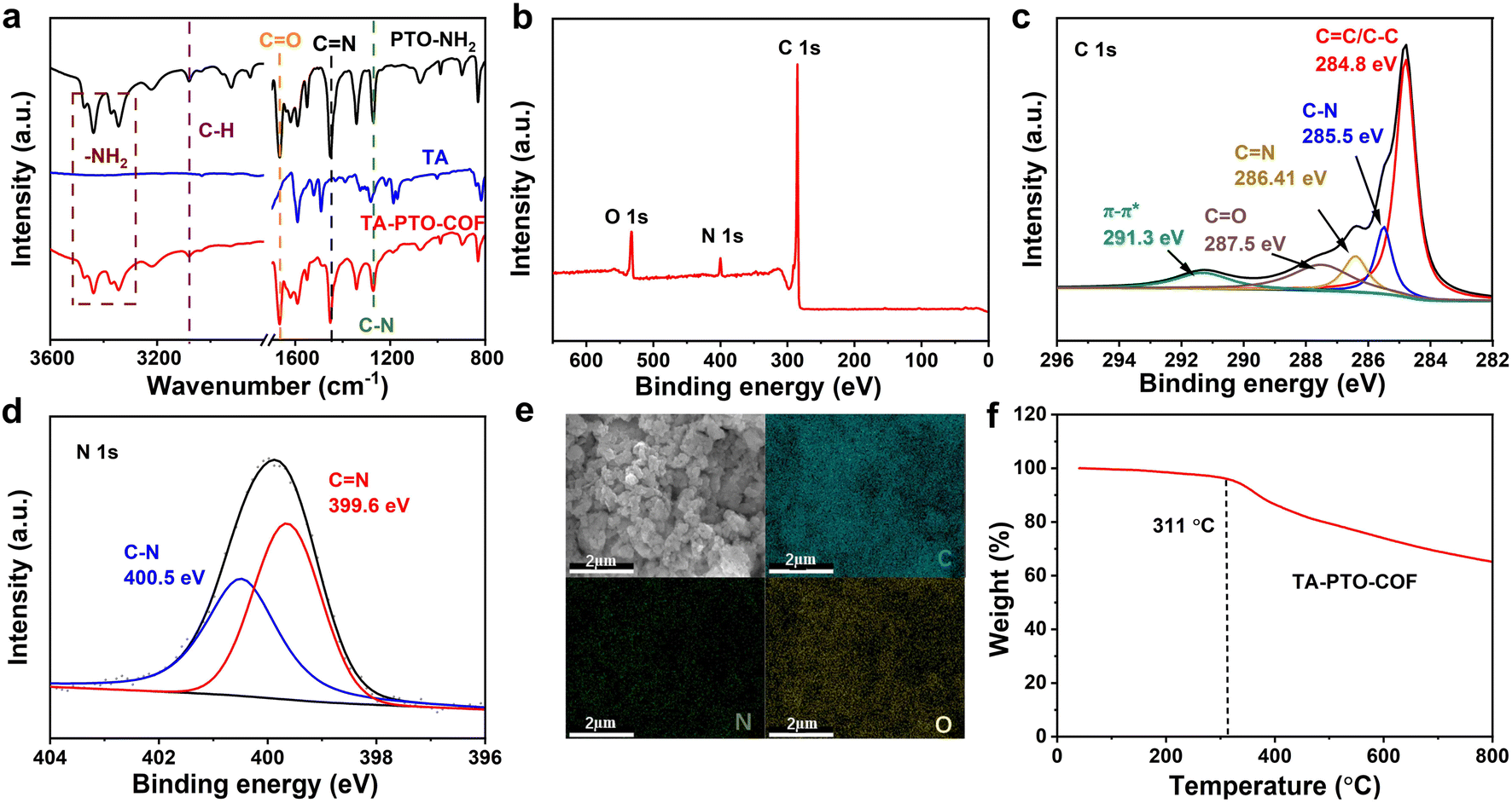 | ||
| Fig. 2 (a) FT-IR spectra of PTO-NH2, TA, and TA-PTO-COF. (b) XPS survey spectrum of TA-PTO-COF. (c) High-resolution C 1s spectrum of TA-PTO-COF. (d) High-resolution N 1s spectrum of TA-PTO-COF. (e) SEM and corresponding elemental C, N, and O mapping. (f) Thermogravimetric analysis of TA-PTO-COF. | ||
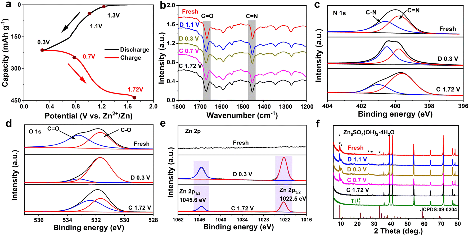
To optimize the electrochemical performance of the TA-PTO-COF cathode, various types of electrolytes were used for comparison (Fig. S5†). Significantly, the TA-PTO-COF cathode using 2 M ZnSO4 electrolyte exhibits more competitive capacity and cycling stability compared to the same cathode with other electrolytes (3 M Zn (CF3SO3)2, 3 M Zn (ClO4)2 electrolytes). When 2 M ZnSO4 was chosen as the electrolyte, the electrochemical performance of TA-PTO-COF was evaluated with the help of cyclic voltammetry (CV) curves at a scan rate of 0.1 mV s−1 to analyze the redox mechanism of TA-PTO-COF, as presented in Fig. 3a. TA-PTO-COF clearly shows two pairs of redox peaks at 0.71/0.78 V and 0.94/1.05 V, respectively, which can be assigned to the coordination of Zn2+/H+ with CO and CN groups in the COF. Importantly, during repeated cycling, the CV curves show a good overlapping characteristic, indicating the outstanding reversibility and chemical stability of the TA-PTO-COF cathode.49 Furthermore, the galvanostatic charge/discharge profiles display a stable voltage plateau (Fig. 3b), which is consistent with the CV curves. The electrochemical stability of the TA-PTO-COF cathode is significantly improved compared to that of the PTO-NH2 monomer (Fig. S6†). The corresponding capacity of TA-PTO-COF is 255 mA h g−1 at 0.1 A g−1 (Fig. 3c), along with a high initial coulombic efficiency (ICE) of 84%. Even after 100 cycles, a reversible capacity of 176 mA h g−1 can be maintained. By contrast, when using the PTO-NH2 monomer as a cathode, only 131 mA h g−1 was retained. The long-term cycling performance of TA-PTO-COF was evaluated at a current density of 1 A g−1 (Fig. 3d). After 1000 cycles, a high capacity of 142 mA h g−1 and a coulombic efficiency of around 100% can be observed. In addition, Fig. 3e shows that the rate capability of TA-PTO-COF and the PTO-NH2 monomer at different current densities ranges from 0.1 to 10 A g−1. Clearly, TA-PTO-COF exhibits high capabilities of 269, 262, 245, 232, 219, 201, 195, and 186 mA h g−1 at 0.1, 0.2, 0.5, 1.0, 2.0, 5.0, 7.0, and 10 A g−1, respectively. More importantly, when the current density returns to 0.1 A g−1, the capacity of TA-PTO-COF returns to its original value, indicating the ideal reversibility and stability. The above results demonstrate that reasonable structural design is conducive to enhancing the electrochemical performance of the organic electrode. The voltage of the pouch cell is shown to be 1.193 V. In addition, the pouch cell operates well (lights LED lamps) without deformation or explosion in a folded condition, indicating a high level of safety of the pouch cell (Fig. 3f–h).
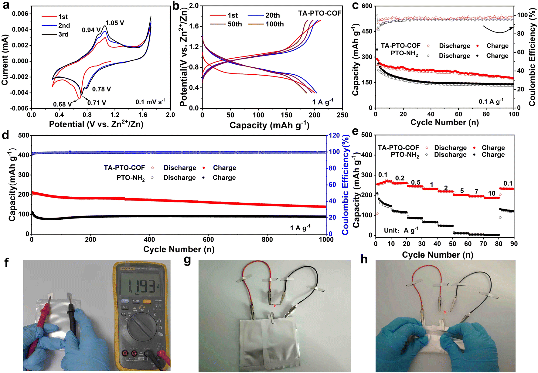 | ||
| Fig. 3 (a) CV curves of TA-PTO-COF at 0.1 mV s−1. (b) Discharge/charge profiles of TA-PTO-COF in 2 M ZnSO4 electrolyte at 1 A g−1. (c) Cycling stability of TA-PTO-COF and PTO-NH2 in 2 M ZnSO4 electrolyte at 0.1 A g−1. (d) Long-duration cycling stability of TA-PTO-COF and PTO-NH2 in 2 M ZnSO4 at 1 A g−1. (e) Rate performances of TA-PTO-COF and PTO-NH2. (f) Open circuit voltage of a pouch cell. (g and h) Photographs of two pouch cells powering red LEDs under different bending angles. | ||
To study the reaction kinetics of TA-PTO-COF, electrochemical impedance spectroscopy (EIS), cyclic voltammetry (CV), and the galvanostatic intermittent titration technique (GITT) were carried out. In the EIS plots of PTO-NH2 and TA-PTO-COF, the charge transfer resistance (Rct) is a concave semicircle in the high-to-middle frequency region. It can be observed that TA-PTO-COF exhibits a smaller charge transfer resistance than PTO-NH2, indicating higher electrical conductivity and improved reaction kinetics (Fig. 4a, b). The CV curves of TA-PTO-COF and PTO-NH2 under 0.1–1.5 mV s−1 are shown in Fig. 4c and Fig. S7a.† The two pairs of redox peaks and same shape of TA-PTO-COF can be clearly observed in the CV curves at different scan rates, indicating its excellent electrochemical reversibility and reaction kinetics.50 Based on the redox peaks and relationship between the peak current (i) and scan rate (v), the b-value can be calculated to evaluate the electrochemical behavior of TA-PTO-COF and PTO-NH2, indicating capacitive behavior (b = 0.5) or diffusion controlled behavior (b = 1.0). The relationship between i and v can be described by eqn (1) and (2):51
| i = avb | (1) |
| log(i) = log(a) + blog(v) | (2) |
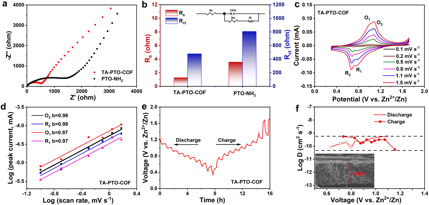 | ||
| Fig. 4 (a) EIS plots of PTO-NH2 and TA-PTO-COF. (b) Impedance fitting diagram of PTO-NH2 and TA-PTO-COF. (c) CV curves of the TA-PTO-COF cathode at various sweep rates. (d) b values of TA-PTO-COF. (e) GITT curves of the TA-PTO-COF electrode (first charge/discharge state). (f) Corresponding quantified DZn2+ at different potential stages and the SEM image of a TA-PTO-COF electrode section. | ||
The b-values of TA-PTO-COF were 0.97, 0.98, 0.97, and 0.98, all close to 1, indicating the dominance of capacitive control, which is beneficial to fast redox kinetics (Fig. 4d). In contrast, the b-values of PTO-NH2 are 0.89 and 0.86 (Fig. S7b†). Moreover, the ion diffusion coefficients of the TA-PTO-COF cathode during the charge/discharge processes were calculated using GITT profiles (Fig. 4e) and the following equation:
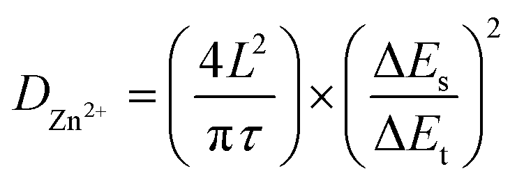 | (3) |
To deeply reveal the electrochemical storage mechanism of the TA-PTO-COF cathode, ex situ FT-IR spectra were recorded. As shown in Fig. 5a and b, in the discharge process, the intensity of the peaks of CO (1660 cm−1) and CN (1452 cm−1) continuously decreases, indicating that both CO and CN are active functional groups in TA-PTO-COF and serve as active sites for Zn2+/H+ storage. In the subsequent charge process, these peaks can recover, revealing the excellent reversibility of the TA-PTO-COF cathode material. Meanwhile, ex situ XPS spectroscopy was conducted to further analyze the reversible electrochemical process. Fig. 5c shows the high-resolution N 1s spectrum of TA-PTO-COF, which exhibits the C–N (400.5 eV) and CN (399.6 eV) bonds. When the electrode was discharged to 0.3 V, the peak of CN bonds shifts slightly toward high binding energy (399.8 eV), accompanied by a reduction in intensity. In contrast, the intensity of the C–N bond gradually increases, primarily due to the consumption of CN and the formation of C–N. When TA-PTO-COF is charged to 1.72 V, the intensity of the CN and C–N bonds can be restored. Importantly, a similar process can be observed in the high-resolution O 1s spectrum, where during the discharge process, the intensity of the CO bond decreases while that of the C–O bond increases (Fig. 5d).43 Additionally, new peaks at 1022.5 and 1045.6 eV appear, which are attributed to Zn species (Fig. 5e). Afterward, the intensity of these peaks returns to the initial state, suggesting the excellent reversibility of TA-PTO-COF. These evolutions of N 1s, O 1s, and Zn 2p spectra confirm the redox activity of CN/CO groups in TA-PTO-COF.
 | ||
| Fig. 5 (a) Charge and discharge profiles of TA-PTO-COF at a current density of 0.1 A g−1. (b) Ex situ FT-IR spectra of the TA-PTO-COF cathode at different potentials. Ex situ XPS analysis of (c) N 1s, (d) O 1s, and (e) Zn 2p. (f) Ex situ XRD patterns of the TA-PTO-COF cathode at different potentials. | ||
Subsequently, ex situ XRD patterns were collected to analyze the storage of Zn2+/H+ during the charge/discharge processes, and the results are presented in Fig. 5f. After discharging to 0.3 V, new diffraction peaks appeared around 8.7°, 10.15°, and 32.57°, which can be ascribed to the Zn5SO4(OH)2·4H2O. During the reaction process, the H+ was embedded in the TA-PTO-COF cathode, resulting in the generation of an equal quantity of OH−. Then, the OH− ions further reacted with ZnSO4 and H2O, leading to the formation of Zn5SO4(OH)2·4H2O. The above results synergistically demonstrate the co-intercalation of Zn2+ and H+ in the TA-PTO-COF. In addition, a three-electrode system test was carried out using different electrolytes (2 M ZnSO4 and 1 M H2SO4) to further confirm the involvement of H+ in the charge/discharge processes (Fig. S8†). The working electrode, counter electrode, and reference electrode used were the TA-PTO-COF cathode, platinum sheet, and Ag/AgCl (in saturated potassium chloride), respectively. The obtained CV curve in the 2 M ZnSO4 electrolyte exhibits two pairs of redox peaks at −0.07/−0.14 V and 0.09/0.19 V.53 Regarding the 1 M H2SO4 electrolyte, the corresponding CV curve displays a reduction peak at 0.40 V and two oxidation peaks at 0.39/0.57 V. Notably, the CV curves in the 1 M H2SO4 electrolyte overlapped with that in the 2 M ZnSO4 electrolyte after shifting, confirming the joint participation of H+ and Zn2+ in the redox process.7
Conclusions
In summary, a new covalent organic framework with dual redox-active sites was synthesized through a simple condensation reaction of TA and PTO-NH2 in a Schiff base reaction. The inherent ordered open channel structure, multiple active sites, π–π stacking structure, and high ion/electron conductivity of TA-PTO-COF facilitate fast reaction kinetics and enhance electrochemical performance. When used as the cathode for AZIBs, TA-PTO-COF shows a high capacity of 255 mA h g−1 at 0.1 A g−1. At the same time, the TA-PTO-COF cathode material also shows great rate performance and cycling stability (1000 cycles at 1 A g−1). The CN and CO bonds in the TA-PTO-COF cathode can reversibly accept/release cations from the electrolyte as determined by ex situ FT-IR and XPS tests. This work demonstrates the potential for commercializing organic cathode materials with dual redox active sites in energy storage devices.
Data availability
The data that support the findings of this study are openly available online.Author contributions
H. B. L. and C. F. Z. designed and guided this study. H. B. L., M. G. C., and Z. L. F. carried out the experiments and materials characterization. Q. W. M., L. H. Z., R. W., F. L., and T. F. Z. contributed to the data analysis and co-wrote the paper. C. F. Z. proposed and supervised the project.Conflicts of interest
There are no conflicts to declare.Acknowledgements
We are thankful for the financial support from the National Natural Science Foundation of China (52172173, 52302205), the Natural Science Foundation of Anhui Province for Distinguished Young Scholars (2108085J25), Excellent Research and Innovation Team Project of Anhui Province (2022AH010001), the Anhui Provincial Natural Science Foundation for Outstanding Young Scholars (2208085Y05), Natural Science Foundation of Anhui Province (2208085QE130), and Distinguished Youth Research Project of Anhui Province (2022AH020013). We also acknowledge the High-performance Computing Platform of Anhui University for providing computing resources.Notes and references
- Y. Chen, H. Dai, K. Fan, G. Zhang, M. Tang, Y. Gao, C. Zhang, L. Guan, M. Mao, H. Liu, T. Zhai and C. Wang, Angew. Chem., Int. Ed., 2023, 62, e202302539 CrossRef CAS PubMed.
- M. R. Biradar, A. V. Salkar, P. P. Morajkar, S. V. Bhosale and S. V. Bhosale, J. Energy Storage, 2022, 48, 103953 CrossRef.
- J. Pan, Z. Xia, N. Deng, L. Chen, H. Zhang, Y. Lu, Y. Liu and H. Gao, Chem. Eng. J., 2023, 452, 138607 CrossRef CAS.
- J. Zhou, S. Zhang, Y.-N. Zhou, W. Tang, J. Yang, C. Peng and Z. Guo, Electrochem. Energy Rev., 2021, 4, 219–248 CrossRef CAS.
- C. Zhang, R. Yu, T. Zhou, Z. Chen, H. Liu and Z. Guo, Carbon, 2014, 72, 169–175 CrossRef CAS.
- T. Sun, Z. Yi, W. Zhang, Q. Nian, H. J. Fan and Z. Tao, Adv. Funct. Mater., 2023, 33, 2306675 CrossRef CAS.
- W. Wang, Y. Tang, J. Liu, H. Li, R. Wang, L. Zhang, F. Liang, W. Bai, L. Zhang and C. Zhang, Chem. Sci., 2023, 14, 9033–9040 RSC.
- F. Zhang, M. Wu, X. Wang, Q. Xiang, Y. Wu, J. Ding and Y. Sun, Chem. Eng. J., 2023, 457, 141335 CrossRef CAS.
- Q. Zhang, Z. Wang, S. Zhang, T. Zhou, J. Mao and Z. Guo, Electrochem. Energy Rev., 2018, 1, 625–658 CrossRef CAS.
- J. Wang, Y. Lyu, R. Zeng, S. Zhang, K. Davey, J. Mao and Z. Guo, Energy Environ. Sci., 2024 10.1039/D3EE02978F.
- Z. Liu, R. Wang, Y. Gao, S. Zhang, J. Wan, J. Mao, L. Zhang, H. Li, J. Hao, G. Li, L. Zhang and C. Zhang, Adv. Funct. Mater., 2023, 33, 2308463 CrossRef CAS.
- N. Dong, F. Zhang and H. Pan, Chem. Sci., 2022, 13, 8243–8252 RSC.
- Y. Chen, J. Li, Q. Zhu, K. Fan, Y. Cao, G. Zhang, C. Zhang, Y. Gao, J. Zou, T. Zhai and C. Wang, Angew. Chem., Int. Ed., 2022, 61, e202116289 CrossRef CAS PubMed.
- Z. Liu, R. Wang, Q. Ma, H. Kang, L. Zhang, T. Zhou and C. Zhang, Carbon Neutralization, 2022, 1, 126–139 CrossRef.
- K. Zhu, C. Guo, W. Gong, Q. Xiao, Y. Yao, K. Davey, Q. Wang, J. Mao, P. Xue and Z. Guo, Energy Environ. Sci., 2023, 16, 3612–3622 RSC.
- T. Kakeya, A. Nakata, H. Arai and Z. Ogumi, J. Power Sources, 2018, 407, 180–184 CrossRef CAS.
- S. Ying, J. Zhou, L. Jin, M. Yemin and H. Xuejie, Energy Mater., 2022, 2, 200004 Search PubMed.
- N. T. H. Luu, A. S. Ivanov, T.-H. Chen, I. Popovs, J.-C. Lee and W. Kaveevivitchai, J. Mater. Chem. A, 2022, 10, 12371–12377 RSC.
- R. Zhang, H. Xu, D. Luo, J. Chi, Z. Fan, H. Dou and X. Zhang, Chem. Eng. J., 2023, 458, 141336 CrossRef CAS.
- G. Li, L. Sun, S. Zhang, C. Zhang, H. Jin, K. Davey, G. Liang, S. Liu, J. Mao and Z. Guo, Adv. Funct. Mater., 2023, 34, 2301291 CrossRef.
- Z. Sun, Y. Liu, W. Ye, J. Zhang, Y. Wang, Y. Lin, L. Hou, M.-S. Wang and C. Yuan, Angew. Chem., Int. Ed., 2021, 60, 7180–7187 CrossRef CAS PubMed.
- Z. Chen, H. Su, P. Sun, P. Bai, J. Yang, M. Li, Y. Deng, Y. Liu, Y. Geng and Y. Xu, Proc. Natl. Acad. Sci. U. S. A., 2022, 119, e2116775119 CrossRef CAS PubMed.
- H. Li, J. Wu, H. Li, Y. Xu, J. Zheng, Q. Shi, H. Kang, S. Zhao, L. Zhang, R. Wang, S. Xin, T. Zhou and C. Zhang, Chem. Eng. J., 2022, 430, 132704 CrossRef CAS.
- H. Xun, Z. Chen, Y. Liu, H. Su, J. Yang, Y. Liu and Y. Xu, ACS Appl. Mater. Interfaces, 2023, 15, 29064–29071 CrossRef CAS PubMed.
- S. Xu, C. Wang, T. Song, H. Yao, J. Yang, X. Wang, J. Zhu, C.-S. Lee and Q. Zhang, Adv. Sci., 2023, 10, 2304497 CrossRef CAS PubMed.
- P. Xiong, S. Zhang, R. Wang, L. Zhang, Q. Ma, X. Ren, Y. Gao, Z. Wang, Z. Guo and C. Zhang, Energy Environ. Sci., 2023, 16, 3181–3213 RSC.
- J. J. Shea and C. Luo, ACS Appl. Mater. Interfaces, 2020, 12, 5361–5380 CrossRef CAS PubMed.
- D. Yao, Y. Zhang, S. Zhang, J. Wan, H. Yu and H. Jin, J. Mater. Chem. A, 2023, 11, 16433–16457 RSC.
- C. N. Gannett, J. Kim, D. Tirtariyadi, P. J. Milner and H. D. Abruña, Chem. Sci., 2022, 13, 9191–9201 RSC.
- F. Baskoro, P.-C. Chiang, Y.-C. Lu, J. N. Patricio, S. D. Arco, H.-C. Chen, W.-S. Kuo, L.-L. Lai and H.-J. Yen, Electrochim. Acta, 2022, 434, 141306 CrossRef CAS.
- Y. Zhai, H. Li, Q. Ma, R. Wang, L. Zhang and C. Zhang, Ionics, 2023, 29, 1301–1310 CrossRef CAS.
- Q. Ma, J. Zheng, H. Kang, L. Zhang, Q. Zhang, H. Li, R. Wang, T. Zhou, Q. Chen, A. Liu, H. Li and C. Zhang, ACS Appl. Mater. Interfaces, 2021, 13, 43002–43010 CrossRef CAS PubMed.
- J. Xiong, X. Yan, H. Yu, C. Wu, G. Zhao, J. Zhang, Y. Dai, X. Wang, J. Gao, X. Pu, M. Hu, J. Liu and J. Yang, J. Mater. Chem. A, 2023, 11, 8048–8056 RSC.
- K. Jia, H. Liu, G. Huang, J. Zhang, X. Liu, L. Li, L. Zhu and F. Wu, J. Mater. Chem. A, 2022, 10, 14917–14922 RSC.
- W. Wang, V. S. Kale, Z. Cao, Y. Lei, S. Kandambeth, G. Zou, Y. Zhu, E. Abouhamad, O. Shekhah, L. Cavallo, M. Eddaoudi and H. N. Alshareef, Adv. Mater., 2021, 33, 2103617 CrossRef CAS PubMed.
- X. Yang, L. Gong, K. Wang, S. Ma, W. Liu, B. Li, N. Li, H. Pan, X. Chen, H. Wang, J. Liu and J. Jiang, Adv. Mater., 2022, 34, 2207245 CrossRef CAS PubMed.
- D. Ma, H. Zhao, F. Cao, H. Zhao, J. Li, L. Wang and K. Liu, Chem. Sci., 2022, 13, 2385–2390 RSC.
- S. Li, Y. Liu, L. Dai, S. Li, B. Wang, J. Xie and P. Li, Energy Storage Mater., 2022, 48, 439–446 CrossRef.
- H. Zhao, D. Luo, H. Xu, W. He, B. Ding, H. Dou and X. Zhang, J. Mater. Sci., 2022, 57, 9980–9991 CrossRef CAS.
- X. Liu, Y. Jin, H. Wang, X. Yang, P. Zhang, K. Wang and J. Jiang, Adv. Mater., 2022, 34, 2203605 CrossRef CAS PubMed.
- H. Gao, A. R. Neale, Q. Zhu, M. Bahri, X. Wang, H. Yang, Y. Xu, R. Clowes, N. D. Browning, M. A. Little, L. J. Hardwick and A. I. Cooper, J. Am. Chem. Soc., 2022, 144, 9434–9442 CrossRef CAS PubMed.
- Y. Lin, H. Cui, C. Liu, R. Li, S. Wang, G. Qu, Z. Wei, Y. Yang, Y. Wang, Z. Tang, H. Li, H. Zhang, C. Zhi and H. Lv, Angew. Chem., Int. Ed., 2023, 62, e202218745 CrossRef CAS PubMed.
- X.-X. Luo, W.-H. Li, H.-J. Liang, H.-X. Zhang, K.-D. Du, X.-T. Wang, X.-F. Liu, J.-P. Zhang and X.-L. Wu, Angew. Chem., Int. Ed., 2022, 61, e202117661 CrossRef CAS PubMed.
- L. Liang, X. Sun, J. Zhang, L. Hou, J. Sun, Y. Liu, S. Wang and C. Yuan, Adv. Energy Mater., 2019, 9, 1802847 CrossRef.
- M. J. Frisch, G. E. Scuseria, M. A. Robb, J. R. Cheeseman, G. Scalmani, V. Barone, B. Mennucci, G. A. Petersson, H. Nakatsuji, M. Caricato, X. Li, H. P. Hratchian, A. F. Izmaylov, J. Bloino, G. Zheng, J. L. Sonnenberg, M. Hada, M. Ehara, K. Toyota, R. Fukuda, J. Hasegawa, M. Ishida, T. Nakajima, Y. Honda, O. Kitao, H. Nakai,T. Vreven, J. A. Montgomery Jr, J. E. Peralta, F. Ogliaro, M. Bearpark, J. J. Heyd, E. Brothers, K. N. Kudin, V. N. Staroverov, R. Kobayashi, J. Normand, K. Raghavachari, A. Rendell, J. C. Burant, S. S. Iyengar, J. Tomasi, M. Cossi, N. Rega, J. M. Millam, M. Klene, J. E. Knox, J. B. Cross, V. Bakken, C. Adamo, J. Jaramillo, R. Gomperts, R. E. Stratmann, O. Yazyev, A. J. Austin, R. Cammi, C. Pomelli, J. W. Ochterski, R. L. Martin, K. Morokuma, V. G. Zakrzewski, G. A. Voth, P. Salvador, J. J. Dannenberg, S. Dapprich, A. D. Daniels, O. Farkas, J. B. Foresman, J. V. Ortiz, J. Cioslowski and D. J. Fox, Gaussian 16 revision A.03, Gaussian, Inc., Wallingford CT, 2016 Search PubMed.
- Y. Ma, Y. Wei, W. Han, Y. Tong, A. Song, J. Zhang, H. Li, X. Li and J. Yang, Angew. Chem., Int. Ed., 2023, 62, e202314259 CrossRef CAS PubMed.
- S. Zheng, D. Shi, D. Yan, Q. Wang, T. Sun, T. Ma, L. Li, D. He, Z. Tao and J. Chen, Angew. Chem., Int. Ed., 2022, 61, e202117511 CrossRef CAS PubMed.
- L. Lin, Z. Lin, J. Zhu, K. Wang, W. Wu, T. Qiu and X. Sun, Energy Environ. Sci., 2023, 16, 89–96 RSC.
- Y. Liu, Z. Sun, X. Sun, Y. Lin, K. Tan, J. Sun, L. Liang, L. Hou and C. Yuan, Angew. Chem., Int. Ed., 2020, 59, 2473–2482 CrossRef CAS PubMed.
- L. Zhang, R. Wang, Z. Liu, J. Wan, S. Zhang, S. Wang, K. Hua, X. Liu, X. Zhou, X. Luo, X. Zhang, M. Cao, H. Kang, C. Zhang and Z. Guo, Adv. Mater., 2023, 35, 2210082 CrossRef CAS PubMed.
- Y. Zhang, C. Zhao, Z. Li, Y. Wang, L. Yan, J. Ma and Y. Wang, Energy Storage Mater., 2022, 52, 386–394 CrossRef.
- S. Wang, Q. Guo, H. Liu, L. Zhang, C. Zhang, T. Zhou, Q. Ma, H. Li, R. Wang and Y. Zheng, Chem. Sci., 2024, 15, 1051–1060 RSC.
- X. Wang, Y. Liu, Z. Wei, J. Hong, H. Liang, M. Song, Y. Zhou and X. Huang, Adv. Mater., 2022, 34, 2206812 CrossRef CAS PubMed.
Footnotes |
| † Electronic supplementary information (ESI) available. See DOI: https://doi.org/10.1039/d3sc07013a |
| ‡ These authors contributed equally to this work. |
| This journal is © The Royal Society of Chemistry 2024 |