 Open Access Article
Improving the efficiency of quantum dot-sensitized solar cells by increasing the QD loading amount
Zhengyan
Zhang†
,
Wenran
Wang†
,
Huashang
Rao
 ,
Zhenxiao
Pan
 * and
Xinhua
Zhong
 *
*
Key Laboratory for Biobased Materials and Energy of Ministry of Education, Guangdong Laboratory for Lingnan Modern Agriculture, College of Materials and Energy, South China Agricultural University, Guangzhou 510642, China. E-mail: zxpan@scau.edu.cn; zhongxh@scau.edu.cn
First published on 8th March 2024
Abstract
In quantum dot-sensitized solar cells (QDSCs), optimized quantum dot (QD) loading mode and high QD loading amount are prerequisites for great device performance. Capping ligand-induced self-assembly (CLIS) mode represents the mainstream QD loading strategy in the fabrication of high-efficiency QDSCs. However, there remain limitations in CLIS that constrain further enhancement of QD loading levels. This review illustrates the development of various QD loading methods in QDSCs, with an emphasis on the outstanding merits and bottlenecks of CLIS. Subsequently, thermodynamic and kinetic factors dominating QD loading behaviors in CLIS are analyzed theoretically. Upon understanding driving forces, resistances, and energy effects in a QD assembly process, various novel strategies for improving the QD loading amount in CLIS are summarized, and the related functional mechanism is established. Finally, the article concludes and outlooks some remaining academic issues to be solved, so that higher QD loading amount and efficiencies of QDSCs can be anticipated in the future.
Introduction
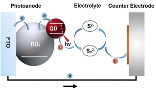
The massive consumption of fossil energy has led to a global energy crisis and environmental pollution, urging people to explore high-performance, cost-effective, and renewable energy. Solar cells based on colloidal quantum dots (QDs) have been regarded as a promising candidate among the new generation of photovoltaic devices due to the superior optoelectronic properties of the light-harvesting materials, facile solution-processable fabrication, superior stability, and low cost.1–5 They can be mainly classified into heterojunction QD solar cells and QD-sensitized solar cells. Heterojunction QD solar cells resemble conventional p–n junction solar cells, in which the electron hole is separated by a heterojunction.6 In this type of solar cell, lead chalcogenide QDs (PbS and PbSe) were mainly used as promising photovoltaic materials before 2015.7–10 Immediately, perovskite-based QDs (PQDs) became the dominant absorber material accompanied by the emergence of PQDs synthesized by hot-injection.11 Although PQDs combine many of the lead chalcogenide characteristics of traditional QDs with the optoelectronic properties of perovskite semiconductors, allowing researchers to manipulate QD properties by changing their composition, size, and shape, they are incompatible with solvent (water).7,12 Hence, PQDs are rarely used in QD-sensitized solar cells (QDSCs). Compared to heterojunction solar cells that are mostly composed of environmentally hazardous cadmium (Cd) and lead (Pb), the light-harvesting materials in QDSCs are mostly green without Cd or Pb, which is one of the key factors for guaranteeing competitiveness. In addition, in QDSCs, the electrons are rapidly injected into the TiO2 substrate, and the rate of electron injection is mainly related to the properties of TiO2 rather than the properties of the QD light absorber. Consequently, it relaxes the high-quality requirement of QDs, permitting some of the transport restrictions to be bypassed in heterojunction solar cells.13QDSCs are derived from the prototype of dye-sensitized solar cells (DSCs), consisting of a photoanode, electrolyte, and counter electrode. The photoanode is composed of a metal oxide (typically TiO2) substrate loaded with QD sensitizers. The metal oxide substrate collects and transports the photogenerated electrons to the external circuit. The electrolyte redox couples (typically sulfur/polysulfide) reduce the leftover photogenerated holes and regenerate QDs. The counter electrode, which is usually composed of a catalytic material (typically carbon and metal sulfides) and conductive substrate, is used to catalyze and reduce the electrolyte. A schematic device structure is shown in Fig. 1.
Loading the amount of QD sensitizers on a photoanode plays a vital role in harvesting incident sunlight and determining the efficiency of solar cells. High coverage of QD sensitizers on the TiO2 photoanode not only ensures increased light absorption capacity that benefits high Jsc levels but also blocks TiO2/electrolyte interfaces that suppress undesired interfacial charge recombination, which is beneficial for the improvement of Voc and FF. Besides, the high QD loading amount can reduce the necessary thickness of the photoanode, indicating that the probability of charge recombination decreases due to the shorter electron transport distance.14,15 Therefore, the fabrication of photoanodes with high QD loading amounts is a viable and economical way to further improve device efficiency. In the early years, the application and development of mesoscopic TiO2 with large specific areas and moderate porous structures is a milestone, because it provides abundant channels and sites for the penetration and deposition of QDs.14,16–18 Correspondingly, suitable QD loading strategies adapting to the feature of mesoscopic substrates are developed in order to realize high QD loading levels. In 2012, Zhong's group developed a capping ligand-induced self-assembly (CLIS) QD deposition strategy.19 In this method, QDs with high quality are synthesized first by the organometallic high-temperature synthesis method. The undesired inert long carbon chain ligands are then replaced by short and bifunctional ones, such as 3-mercaptopropionic acid (MPA). The strong interactions of the terminal carboxyl group in MPA with TiO2 act as strong loading driving forces. As a result, high QD loading amount can be realized within a dramatically decreased deposition time. Since then, CLIS has become the mainstream method for the construction of photoanodes in QDSCs. Accompanied by the development of various other strategies, such as the design and tailoring of QD light-harvesting materials,20–26 control of charge recombination kinetics,27 additive engineering of electrolyte,28–30 catalytic ability enhancement of the counter electrode, etc.,31–34 the efficiencies of QDSCs have rapidly increased from less than 5% in 2012 to over 16% in 2023.20,21,35–40
However, the current efficiencies of QDSCs are still far below the theoretical level of 44%. It is recognized that there remains room to enhance efficiencies by further increasing the QD loading amount. Unfortunately, QD loading seems to be restricted by conventional CLIS methods. In a QD loading process, QDs leave the solution phase and adsorb on specific sites of TiO2 substrates. Effective loading should be facilitated by strong enough driving forces, while the presence of resistance hinders QD loading. In CLIS, the attractive interactions between QDs and the substrate, such as electrostatic forces and covalent bonds, serve as effective driving forces. The related action mode and strength dictate QD loading behavior. Meanwhile, a series of undesired factors prevent QDs from approaching loading sites to form a dense QD adsorption layer. For example, strong interactions between QDs and solvent molecules (solvation) prevent QDs from leaving the solution phase. In addition, regarding surface physicochemistry, there are repulsive interactions between QDs and substrates that weaken QD loading driving forces. Furthermore, the comparable size of QDs to the micropores in the TiO2 substrate prevents the penetration of QDs deeply into the substrates, and the interdot repulsions hinder the formation of compact QD deposition layers. These are conceived as QD loading resistances. As a consequence, to further promote QD loading, there remains room for increasing loading driving forces and, particularly, reducing loading resistance. Understanding the origin of driving forces and resistances both in thermodynamic and kinetic behaviors is the requirement for the design and development of novel modification strategies.
In the past years, a series of effective modification methods have been reported to promote QD loading, and the related investigations are systematic. There have been excellent comprehensive reviews in the field of QDSCs and thematic reviews in the aspects of device construction, the design of QD materials, control of charge recombination, exploration of new counter electrodes, etc.4,6,13,27,41 Since high QD loading amount is essential for the enhancement of QDSC performances, a specific review to summarize these studies and related loading mechanisms is necessary. This review begins with an analysis of the QD loading process, unraveling the QD loading mechanism with an emphasis on loading driving forces and energy effects. Subsequently, the reported diverse strategies to improve the QD loading amount, including solvent engineering, QD ligand design, TiO2 photoanode surface modification, secondary QD deposition, etc., are summarized. The relations among boosted QD loading amount, device performance, and the related optimized QD loading mechanism are elaborately established. Finally, upon summarizing the review, some limitations and issues that have been less understood in QD deposition are addressed. This review is helpful for the understanding, design, and optimization of photoanodes with high QD loading amounts so that QDSCs with higher efficiencies can be realized in the near future. Additionally, the knowledge related to efficient QD deposition is also illuminative in many other fields, such as nanocrystal assembly, nanodevice fabrication, etc.
Development of QD loading strategies
QD loading amount is determined by QD synthesis and assembly processes. The development and features of various QD deposition methods are discussed in this section.In situ QD synthesis
QD deposition modes can be divided into in situ and ex situ approaches (Fig. 2a). In in situ methods, QDs are directly synthesized on TiO2 surfaces. The TiO2 substrate facilitates the heterogeneous nucleation of QDs, and subsequent QD growth is viable. Conventional solution-processable strategies based on ionic precursors, such as chemical bath deposition (CBD) and successive ionic layer adsorption and reaction (SILAR), represented the popular in situ methods.23,42,43 In the CBD method, the TiO2 film is immersed in the mixed solution simultaneously containing cationic and anionic precursors. The size of QDs can be controlled by adjusting the immersion time and the physicochemical properties of the precursor solution.44,45 Considering the fact that the cationic and anionic precursors cannot coexist in a solution in some cases, the developed SILAR deposition is also a widely used method of in situ approach, in which the TiO2 mesoporous films are alternately immersed into the precursor solutions containing cations or anions, to grow QDs. The size and loading amount of QDs can be effectively regulated by controlling the number of SILAR cycles. Both CBD and SILAR methods permit QDs to grow directly on the surface of TiO2 mesoporous films, thereby achieving a high QD loading amount and bearing the advantages of facile processability and reproducibility.13 Besides, the direct growth of QDs on TiO2 mesoporous films can enhance the interfacial electronic communication between QDs and TiO2. This is conducive to facilitating charge separation and transport. However, some unavoidable problems are hindering the development of in situ approaches. In in situ methods, the related QD nucleation and growth kinetics are unoptimized due to the uncontrollability of ionic reaction processes. As a result, the low crystalline quality, high defect concentrations, and uncontrollable morphology of QDs account for severe charge recombination.46,47 Therefore, the performance of QDSCs based on CBD or SILAR is fundamentally low, with power conversion efficiency (PCE) generally below 7%.23,46,48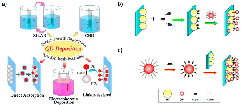 | ||
| Fig. 2 (a) Schematic diagram of different QD deposition approaches of in situ (SILAR and CBD) and ex situ QD loading (DA, EPD, and LAA) approaches. Scheme of the (b) in situ ligand exchange linker-assisted and (c) the CLIS for QD deposition. This figure has been adapted/reproduced from ref. 41 with permission from American Chemical Society, copyright 2015. | ||
Ex situ QD loading
It is recognized that if QDs can be pre-synthesized through high-temperature synthetic methods with low defect concentrations, followed by being assembled into mesoporous TiO2 film electrodes from colloidal QD solutions, the limitations of undesired charge dynamics can be overcome, and the efficiencies of QDSCs can be enhanced fundamentally.20–22 The related QD deposition methods are referred to as ex situ methods, including direct adsorption (DA), electrochemical deposition (EPD), and linker-assisted assembly (LAA) (Fig. 2a). However, the feature of pre-synthesized QDs brought in challenges in terms of efficient QD loading. In DA, QD deposition is realized by immersing TiO2 in purified QD solutions.14,49 Unfortunately, lacking efficient loading driving forces, the DA of QD is faced with great steric and kinetic resistance, and the high QD loading amount is still obstructed. The size of QDs is comparable to the micro pores and channels within the TiO2 mesoporous film, leading to a troublesome QD penetration. In addition, the bulky and insulating ligands from synthesis (oleylamine, oleic acid, phosphine, etc.) make them highly soluble in nonpolar solvents, and it is difficult for the QDs to establish strong enough affinity with the TiO2 substrate. Besides, the DA approach results in QD agglomeration that deteriorates the PCE of the resulting cells.50 EPD is also a viable method to load the pre-synthesized QDs on the metal oxide substrates. In EPD, the charged particles in the liquid are deposited on the electrode driven by an electric field.51 The mass of the deposited particles or the thickness of the films can be controlled by the concentration of the suspension, applied potential, and deposition time.52–54 Besides, the high dielectric constant helps the movement of nanoparticles and the relatively smaller particles. The lower potential benefits the uniform and rigid film deposition of nanoparticles during the deposition in EPD. Compared with the method of DA, the EPD notably decreases the loading period and increases the loading amount of QDs.55 Correspondingly, the QDSCs fabricated by the EPD method exhibit higher PCE and Jsc values. However, in the EPD process, the applied voltage cannot be very large, or else undesired side electrolytic reactions can occur at the electrodes. Unfortunately, the pre-synthesized QDs in nonpolar solvents are almost neutral. As a result, the permitted small voltages provide limited QD loading driving forces in practice. Correspondingly, the efficiencies based on EPD are typically lower than 5%.56–58Linker-assisted assembly (LAA) is another method to deposit pre-synthesized QDs on the TiO2 substrate. Linkers are molecules containing bifunctional groups with two terminals, represented by MPA,19,59–61 thioglycolic acid (TGA),62,63 4-mercaptobenzoic acid (MBA), etc,62,64,65 which indicates that they can simultaneously bind with QDs and TiO2 surfaces. As a result, linkers can induce QD loading by providing chemical bonds as loading driving forces. The LAA methods can be divided into in situ and ex situ modes. As shown in Fig. 2b, in in situ mode, the surface of mesoporous TiO2 is first functionalized by soaking TiO2 films in a solution containing linker molecules, and then the functionalized TiO2 films are immersed in the QD solution to realize QD loading. In this process, the linker molecules on the TiO2 substrate display the role of loading sites and directly coordinate with cationic ions on the surface of QDs. Relative to the DA method, the interactions between TiO2 electrodes and QDs are enhanced by the bifunctional linkers, which effectively enhance the QD loading amount. However, the characteristic disadvantages of DA, such as steric hindrance, long deposition period, irreproducibility of experiments, etc., remain unsolved. The ex situ LAA approach, also termed CLIS, has been developed to avoid the above shortcomings. Different from the in situ LAA approach, the linker molecules are functionalized on the QD surface before loading, rather than on the TiO2 surface (Fig. 2c). In detail, the original ligands on the surface of QDs are first replaced by the bifunctional linker molecules (such as MPA) via ligand exchange strategies.41,66 Solution phase ligand exchange in CLIS results in robust ligand exchange with almost no residue of original ligands.67 The thiol groups at the end of the linker molecule can strongly bind with the QD surface during the process of ligand exchange, while the carboxyl group terminal is exposed as the cohesive ends.68 Besides, the QDs are eventually dispersed in polar solvents such as water, and the charged QD surface can effectively prevent QD agglomeration. Subsequently, the QDs capped with linkers are loaded on the TiO2 substrate via a self-assembly process. The surface bifunctional ligands not only relieve steric hindrance for QD loading but also serve as linker molecules that strongly bind with the TiO2 substrate by forming chemical bonds, which provides efficient loading driving forces.69 As a consequence, CLIS significantly enhances the surface coverage of QDs on TiO2 to as high as 34%; meanwhile, the time required for efficient QD loading is significantly reduced.19 Since then, the CLIS deposition method has been successfully applied to a series of QDs (CdSe0.45Te0.55, CuInS2, Zn–Cu–In–Se, Zn–Cu–In–S–Se, etc.) with narrower bandgaps to increase the efficiency of QDSCs, which greatly promoted the development of QDSCs with a record PCE of 16.2% currently.20–22 Despite the great potential for the CLIS deposition method in improving the QD loading, the underlying limited QD coverage (34%) on the TiO2 surface remains a problem. This indicates that QD loading driving force and resistance demand further optimization in the CLIS process to further promote QD loading. In the following sections, the QD deposition mechanism is analyzed to illustrate the remaining limitations in CLIS.
QD loading mechanism: driving forces, resistances, and energy effects
QD loading is accompanied by the state change of QDs from the colloidal dispersed state to an adsorbed immobile state. Understanding thermodynamic and kinetic factors in the QD loading process is important for the design and development of pertinent modification strategies. In this section, the related QD loading driving forces, resistances, and energy effects are illustrated.Evaluation of QD loading amount and an ideal QD deposition model
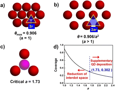
The ideal deposition of QDs on the substrate film aims to achieve full coverage on the film surface with monolayer adsorption. For a fixed thickness of the photoanode, the QD loading amount can be semi-quantified by the absorbance from adsorption spectra. To further analyze QD loading behavior, the QD loading amount is evaluated by the coverage of the substrate, and an ideal QD deposition model is proposed. As shown in Fig. 3, the following conditions are presumed in this model. (1) The substrate for QD deposition is flat; (2) QDs are equally spheres with identical circular projections (the radius is denoted as r); (3) deposited QDs form a monolayer; (4) deposited QDs are uniformly distributed and closely packed, and the distance between two adjacent sphere centers (interdot distance) is described by a nondimensional coefficient a (a ≥ 1) with the interdot distance of 2ar. As shown in Fig. 3a, for close-packed QDs, the maximum coverage at a = 1 (θmax) is calculated to be 0.906 according to geometry. As the interdot distances increase with increased value (Fig. 3b), QD coverage (θ) can be further estimated according to the following equation:| θ = Spro/Stot = 0.906/a2 |
It should be noted that a real QD deposition circumstance usually violates the above ideal assumptions, e.g. size distribution of QDs, mesoscopic substrates, even the formation of QD multilayers, etc. Therefore, evaluating a real QD loading amount based on QD coverage can lead to error. However, the ideal QD loading model still guides the design and construction of photoanodes with high loading amount. Meanwhile, a critical a value of 1.732 and the corresponding critical value θ of 0.302 indicate that the QD layer is sparse enough to accommodate foreign QDs (Fig. 3c). Note that the reported highest θ value is about 0.37,35 which is rather close to the critical θ value but lags far behind the geometrical maximum coverage (0.906). Based on the model, two methodologies to improve the QD loading amount can be applied. (1) The increase in QD loading amount can be translated to the construction of a QD deposition layer with enhanced compactness. To increase the QD compactness, the reduction of the value of a can contribute to the significant increase of θ values, especially at a small a region, as indicated by the steep slope of the inverse square curve (Fig. 3d). (2) If QD distribution is sparse enough with a relatively large a value, an additional QD loading step to supplement QD loading is beneficial.
Influence of driving forces, resistances, and energy effects on the QD deposition process
QD deposition is, in essence, a solid–liquid adsorption process, where QDs dissolve out from the solution and deposit at specific adsorption sites. In this process, QDs should overcome solvation energy (Esol) to leave the solution phase, and eventually deposit on the TiO2 substrate by releasing the potential energy (U). In principle, the interactions of QD-solvent, QD–TiO2, and QD–QD synthetically account for QD loading driving forces and energy effects, which need to be considered comprehensively. High QD loading levels rely on the following factors: (1) the destruction of interaction between QDs and solvent molecules, (2) the excavation of the driving forces between QDs and TiO2 substrates, and (3) the appropriate interactions among QDs. In the following subsections, the major types of microscopic interactions and their influence on QD loading are discussed.Solvation effect
The solvation effect plays two roles. The first one is the establishment of strong interactions between the QD solute and solvent molecules so that QDs can be dispersed in solvent. In addition, after solute dissolution, the attractive intermolecular forces among dispersed solute particles trigger solute precipitation. Therefore, the second role of the solvation effect is to provide sufficient repulsive forces among QD particles to maintain the dispersity of a solution. The solvation effect of colloidal QDs is dependent on surface ligands and solvent molecule properties. In a nonpolar solvent, QDs are capped with a layer of surface-tethered hydrocarbon chains (oleylamine, oleic acid, trioctylphosphine, etc.). In this situation, the free energy of hydrocarbon chain-solvent mixing is negative, so the ligands adopt a stretched configuration to increase the contact with the liquid environment (Fig. 4a). As a consequence, the hydrocarbon chains provide elastic repulsion forces, penalizing the overlap of ligand coronas and stabilizing QD dispersions. In a polar solvent, the surface of the solute must be charged to accommodate polar solvent molecules, and MPA-capped QDs dispersed in water are a typical example. The high polarity of solvent with a large dielectric constant can effectively screen interparticle electrostatic attractions. In addition, the charged surface must provide sufficient interparticle repulsions to maintain colloidal stability. The interaction potential between a pair of charge-stabilized QDs, including both the double layer repulsion and van der Waals attraction, can be treated using Derjaguin, Landau, Verwey and Overbeek (DLVO) theory. Well-solvated solutes exhibit large enough solvation energies. The destruction of the solvation effect can be applied by disturbing the interactions of solute with solvent molecules, accompanied by the reduction of solvation energy. For QDs, desolvation can be realized by changing the polarity of solvent and altering the properties of capping ligands. In nonpolar solvents, the introduction of polar orthogonal solvents will reduce the affinity of hydrocarbon chains with solvent, and partial detachment of ligands can also promote the reduction of solvation energy. In polar solvents, the introduction of a nonpolar orthogonal solvent will significantly reduce the screening effect from solvent (Fig. 4b). Besides, the introduction of ionic electrolytes will destroy the surface charged layer of QDs. As a result, the interdot repulsions are weakened, and van der Waals attractions predominate the dissolution of QDs. To conclude, although solvation is important for the synthesis of colloidal QD solutions, it acts as the resistance for QD loading. To improve QD loading, it is highly desired to overcome solvation but prevent excessive QD–QD attractions.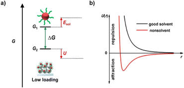 | ||
| Fig. 4 (a) Gibbs free energy (G) diagram of QDs in the QD deposition process. (b) Interaction potential U with interparticle distance r for NCs in the good solvent and nonsolvent that are also termed as polar and non-polar solvent. This figure has been adapted from ref. 70 with permission from American Chemical Society, copyright 2019. | ||
Electrostatic forces
Electrostatic forces are based on the coulombic interactions of charged species, which is universal in a charged system. Due to the coexistence of cations and anions, both attractive and repulsive electrostatics exist. Therefore, electrostatic forces can serve as driving forces and resistances under different circumstances, while the predominant one depends on the electrostatic properties of the system. For example, QDs capped with charged ligands contain surface charge when dissolving in solutions due to the ionization effect. Generally, cations (Na+, K+, NH4+, etc.) are mobile and serve as counterions, while the remaining negatively charged molecule shows strong affinity with the QD surface, contributing to the negative charge in the electric double layer.70 The charged QD surface maintains QD dispersity in solution, as discussed above. Attractive electrostatic forces can serve as effective QD loading driving forces by reducing the potential energy. For example, in the EPD method, applying an appropriate electric field facilitates QD loading.46,51,71 In CLIS mode, when QDs are surrounded by negatively charged, electrostatic forces can serve as nonnegligible resistances that enhance the potential energy. For example, it is found that both the QDs and the acidic TiO2 substrate immersed in QD solution are negatively charged, which limits the QD loading amount. In addition, the charged QD surface will induce interdot repulsions, which serve as the resistance that spoils the construction of a compact QD layer.69,72,73 Therefore, the modulation of charge both on the QD surface and TiO2 substrate represents a major way to improve QD loading.Covalent bond
The covalent bond is formed based on the oriented overlap of the electron cloud from bonding atoms.74 The formation of covalent bonds results in a significant release of potential energy, representing a strong bonding mode. The strength of the covalent bond is determined by the choice of bonding atoms, which is further dictated by the established hard-soft acid-base (HSAB) principle.75 In addition, the electron cloud density and bonding angle also influence bond energy. For example, the inductive and conjugated effects from adjacent functional groups show great influence on the electron cloud density, and the steric effect of bonding molecules influences bonding energies by altering the overlap of the electron cloud.76 Although both possess an electromagnetic origin, covalent bonds are different from electrostatic forces. On one hand, covalent interactions are attractive, so they basically act as QD loading driving forces. On the other hand, the formation of covalent bonds requires saturability and directionality, which is different from electrostatic forces.In CLIS mode, the surface of QDs is functionalized with bifunctional linker molecules, such as MPA. The formation of covalent bonds between the terminal carboxyl group from MPA and Ti sites of substrates has been conceived as the major QD loading driving force in CLIS mode, which is directly responsible for the high QD loading levels. Besides, the saturability and directionality indicate that the covalent bond has great potential to recognize certain loading sites on TiO2 substrates, which in principle is advantageous for the inhibition of QD multi-layer formation.19 As will be discussed later, some strategies can introduce modifiers exhibiting stronger covalent bonds with QDs, and the related loading driving forces are enhanced.
Intermolecular interactions
Intermolecular interactions are divided into van der Waals interactions and other weak interactions.77 The van der Waals interactions can be further classified into induction, orientation, and dispersion forces, which are based on the molecular dipole contributed by the intrinsic polar molecular structure and thermal motion. In addition, some special interactions, represented by secondary bonds (hydrogen bonds, etc.), are also classified into intermolecular interactions. The strength of intermolecular forces is basically weak. For example, van der Waals attractions are inversely proportional to the seventh power of intermolecular distance, and are fundamentally weaker than electrostatic forces and covalent bonds.78 Therefore, although intermolecular interactions are present in all QD loading systems, they become predominant mainly in nonpolar systems. It should be noted that although intermolecular interactions are attractive, in CLIS mode, they can also be regarded as drawbacks if not manipulated properly. For example, excessive intermolecular attractions lead to agglomeration of QDs. As a consequence, the enlarged size of agglomerates hinders QDs from penetrating the micropores of TiO2 substrates, leading to inefficient QD loading. Futhermore, QD agglomerates bring forward new charge recombination centers, which reduce photovoltaic performance of the resulting cells.Complicated cases
It should be noted that various QD loading driving forces can coexist in a real QD loading system. In some cases, synergistic effects from various driving forces are regarded as beneficial factors in promoting QD loading, despite the fact that the different forces are hard to distinguish. For example, the engineering of the photoanode surface using Mg(OH)2 represents a facile way to improve both primary and secondary QD loading.39,79 In primary QD loading, the high isoelectric point and highly basic nature of Mg(OH)2 indicate that electrostatic forces can serve as effective QD loading driving forces.79 In comparison, Mg(OH)2 can serve as a site for the loading of foreign QDs in the secondary QD loading strategy, which indicates that covalent interactions are also possible.39 In some cases, different loading driving forces can be rival, and this is adverse for QD loading. For example, in CLIS mode, ligand deprotonation of the terminal carboxyl group in basic solution has been proven to be beneficial for the formation of covalent bonds that facilitate QD loading,80 while the negatively charged QD surface is regarded as a disadvantageous factor in inducing electrostatic repulsions of QD–TiO2 and QD–QD.73,81 As a result, the construction of a photoanode with dense and compact QD loading is hindered.It is widely observed that after primary QD loading, an additional QD loading step and the introduction of foreign QDs are viable, yet the properties of QDs and/or the photoanode surface properties should be altered.36,52,82–84 This observation indicates that traditional QD loading strategies within one step are usually less efficient, and abundant unoccupied sites remain on TiO2 surfaces. It is inspiring that the utilization and introduction of new sites for QD loading can be regarded as another concept of improving QD loading driving forces. In co-sensitization and secondary QD loading strategies, it appears that different QDs can respond to different loading sites, although the classification and nature of loading driving forces can be unchanged.36,38 The detailed reasons demand further investigation at the molecular level.
Strategies for improving the QD loading amount
High QD loading usually requires large loading driving forces and relieved resistances. Meanwhile, from the viewpoint of molecular assembly, the interactions among QDs should be controlled, so that sufficiently dense QD layers can be formed without undesired agglomeration. In this section, various effective strategies for the enhancement of QD loading amount are summarized in CLIS.Solvent engineering
In CLIS, the formation of chemical bonds between QD surface ligands and cationic Ti sites of the substrate has been generally recognized as the major contributor to high QD loading amount. The ligands are usually terminated by the carboxyl group, and the pH of the solvent determines deprotonation. This can not only determine the dispersion of QDs but also influence the strength of chemical bonds, thus affecting the adsorption of QDs. Lower pH (typically <7) of aqueous QD solution has been demonstrated against the efficient loading of QDs on the TiO2 film due to the formation of undesirable QD agglomeration.59,73 This accounts for a weak interaction between QDs and TiO2 and blocks the channels for further diffusion of QDs. In comparison, higher pH values (pH > 10.5) have been demonstrated to support the loading of QDs on the TiO2 film.69,81,85 Although the coulombic repulsion between QDs and TiO2 (TiO2 is an acidic oxide, whose isoelectric point is around 6.6–7.0) would prevent the binding of QDs to the oxide surface,86 the negatively charged QDs can persistently diffuse into the meso-TiO2 films. At the same time, high pH values also benefit the formation of coordination bonds between QDs and Ti, which contributes to the formation of sub-monolayer surface coverage of QDs on the TiO2 substrate as well as a high QD loading amount. Zhong's group has systematically investigated and optimized the basicity of aqueous QD solution.80 As shown in Fig. 5a and b, the higher pH value of the QD solution benefits the QD loading on the TiO2 substrate and QD dispersion in solution. At high pH, the deprotonation of ligands is effective which facilitates the formation of chemical bonds, and the undesired QD agglomeration can be effectively prevented due to strong interdot repulsion. Comprehensively, monodisperse QDs can effectively penetrate mesoporous TiO2 film electrodes, and an optimized large QD loading amount can be realized.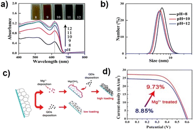 | ||
| Fig. 5 (a) Absorption spectra of CdSe QD-sensitized TiO2 films under different pH conditions and (b) dynamic light scattering graphs of CdSe QD aqueous solutions of different pH values. This figure has been adapted/reproduced from ref. 80 with permission from The Royal Society of Chemistry, copyright 2015. (c) Schematic illustration of the Mg2+ treatment for fabricating QDSCs and (d) J–V curves of QDSCs with and without Mg2+ treatment.79 This figure has been adapted/reproduced from ref. 79 with permission from American Chemical Society, copyright 2016. | ||
Design of TiO2 and surface engineering
The properties of TiO2 (such as surface area, inner pore structure, isoelectric point, etc.) have an indispensable impact on QD loading. The strategies to improve the QD loading amount can be divided into physical and chemical methods, including increasing the surface area to provide enough QD adsorption sites, enlarging the pore size of the TiO2 particles to avoid QD accumulation, and modifying the TiO2 surface. Unlike dye molecules, QDs have a larger size (diameter of several nanometers), indicating that the penetration and loading of QDs in mesoscopic TiO2 are accompanied by resistances. In the early stage, large-size TiO2 particles (300 nm) were introduced into the TiO2 nano-structure to increase the TiO2 void structure. The wider pore size distribution is supposed to inhibit the phenomenon of QDs blocking the channel of TiO2, thus increasing the loading amount of QDs.43 However, the introduction of large TiO2 particles also reduces the specific surface area of the TiO2 substrate, thus reducing the adsorption sites of QDs.87 Therefore, the application of small TiO2 particles (such as Degussa P25) with large specific areas is the wise choice for the construction of photoanodes. The properties of TiO2 can also be modified by introducing suitable reagents. Wang et al. developed a facile technique for enhancing the loading amount of QDs by treating the TiO2 film with metal salt aqueous solutions (Fig. 5c).79 The increased isoelectric point is believed to relieve undesired electrostatic repulsions and promote QD loading. Combined with high-QD loading amount and retarded charge recombination, the champion cell based on Mg2+ treatment exhibited an efficiency of 9.73%, which is significantly higher than that of the untreated cells with the highest efficiency of 8.85% (Fig. 5d).QD surface ligand design
Surface ligands around QDs can control the dispersion stability and the agglomeration of QDs in the solvent, affecting the solvation effect during the deposition of QDs on the TiO2 substrate. In addition, the interaction between the functional groups of the surface ligands and the mesoporous TiO2 surface is an important factor that determines the driving force of QD adsorption. Therefore, the choice and optimization of QD surface ligands play an important role in the deposition of QDs. However, the use of insulating long-chain alkanes ensures the optical properties of QD in the process of QD synthesis, but the weak interaction between these long-chain ligands and the TiO2 substrate, and the large steric hindrance also contribute to the poor QD loading. Therefore, one of the crucial components of high-loading QDSCs is the replacement of long-chain organic ligands with atomic/inorganic/small organic molecular ligands.7There are mainly two ligand exchange methods: solid-state ligand exchange and solid-state ligand exchange, which have been widely used on heterojunction QD solar cells.88,89 The method of ligand exchange brings the QDs closer, enhancing the conductivity of QD films and leading to a dense solid with increased optical absorption.90 In solid-state heterojunction solar cells, it is the thickness of the light-harvesting layer that determines the ability to harvest the incident light, and thus there is no problem with the QD loading. However, in QDSCs, the porous TiO2 is very thick (tens of microns), and thus QD loading inevitably becomes the problem that hinders the improvement of the corresponding solar cell. Thus, we mainly discussed methods for how to improve the loading amount based on solution-phase ligand exchange in QDSCs below.
Zhong's group studied the influence of different lengths of linker molecules (TGA, MPA, and cysteine (Cys)) on the QD loading amount of CLIS (Fig. 6a).91 Experimental results indicate that the loading amount of CdSe QDs follows the order of TGA > MPA > Cys. The higher QD loading amount can be attributed to the factor that small ligands provide stronger intermolecular forces, which can lead to minor QD aggregation in solution that leads to larger domains in the film state. Furthermore, tightly packed QD films with short QD ligands exhibit higher thermal transport, which is an important factor in the preparation of high-performance QDSCs. In all, small ligands would allow for higher QD packing density. The introduction of inorganic ligands (ILs) is also a method to form covalent bonds to improve the QD loading amount.92 Initially, a hybrid passivation strategy is employed to modify the surface of colloidal CdSe QDs for QDSCs. The experimental results show that the introduction of iodide anions not only can effectively remedy the surface defects but also effectively increase the coverage of QDs on TiO2 electrodes.93 Zhong's group employed thiosulfate (S2O32−) and sulfide (S2−) as ligands to get access to the IL capped CdSe QDs and constructed the QDSCs as shown in Fig. 6b.94 The terminal group of S2O32− (soft chalcogenide) shows high binding affinity toward Cd2+ surface on CdSe QDs, and the other terminal group (hard oxoanion) also has strong interaction with TiO2 surface. Therefore, S2O32− QDs have a higher loading amount on the TiO2 film in comparison with those from the OAm and S2− capped QDs.94 As shown in Fig. 6d, Kim's group has also introduced inorganic ligands (such as SnS44− and S2−) for CdSe QDs and successfully deposited them onto TiO2.74 Recently, a facile and effective ligand design strategy has been developed to improve the loading amount by decorating the QD surface with dual ligands (MPA and ILs) by Zhong's group. The report suggested that the coexistence of ILs (such as SCN−) with MPA can serve as effective cross-linkers. Besides, the existence of ILs can reduce solvation energy that facilitates QD loading. They investigated the effects of a series of ILs on the adsorption capacity of QDs (Fig. 6e). The coordination strength between ILs and QD surface metal atoms can be predicted based on the established HSAB principle.95 Relatively soft species (Cl−, Br−, I−, SCN−, S2−, and S2O32− ions) can form coordination bonds using halide or terminal sulfur atoms. Therefore, they form strong coordination bonds with soft chalcogenide QDs, and thus can effectively crosslink adjacent QDs, reducing the QD–QD distance. Among them, the linear SCN− ligand is special because it is bidentate with the ability to form coordinate bonds simultaneously by using soft sulfur and nitrogen atoms (Fig. 6f and g), considering that the cyan group is soft.96,97 Based on the dual ligands of SCN/MPA, ZCISSe QDSC ligands delivered a certified efficiency of 16.10%, which is a new record efficiency for liquid junction QD solar cells.
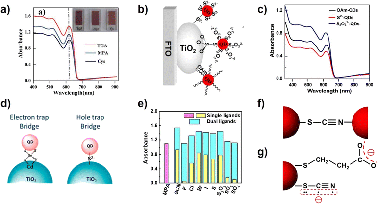 | ||
| Fig. 6 (a) Absorption spectra of TGA-, MPA-, and Cys-capped CdSe QD sensitized TiO2 films. (Inset): photographs of films sensitized with different molecules linked to CdSe.91 This figure has been adapted/reproduced from ref. 91 with permission from The Royal Society of Chemistry, copyright 2014. (b) Schematic diagram and (c) absorption spectra of OAm-, S2−-, and S2O32−-capped CdSe QDs adsorbed on TiO2.94 This figure has been adapted/reproduced from ref. 94 with permission from American Chemical Society, copyright 2017. (d) Illustration of the SnS44− and S2− ligand-capped QD anchored TiO2 photoanode.74 This figure has been adapted/reproduced from ref. 74 with permission from American Chemical Society, copyright 2014. (e) Summary of absorbance values at the wavelength of 600 nm from the absorption spectra of QD-sensitized TiO2 films, and (f) the possible bidentate bonding motif of the SCN− ligand acting as a crosslinker for two adjacent QDs. (g) Schematics of the molecular structure and charge distribution of MPA and SCN− ligands on the QD surface.35 The figure has been adapted/reproduced from ref. 35 with permission from American Chemical Society, copyright 2022. | ||
Co-sensitization and secondary adsorption
In CLIS, due to the presence of interdot repulsions, after primary QD loading there remain unoccupied sites that are still available for QD loading. Based on suitable strategies, foreign QDs can continue to adsorb on the surface of TiO2 after primary QD deposition. Co-sensitization is one of the methods to improve the loading amount of QDs in QDSCs, where a different type of QD (usually with a wider bandgap) is applied. Due to the differences in physical and chemical properties, the QDs in sensitization respond to different loading sites, thereby enabling supplemented QD loading. Based on this discovery, Zhong's group adopted CdSe QDs as co-sensitizers to improve the light harvest capability of the ZCISe pre-sensitized TiO2 (Fig. 7a). The results show that co-sensitization with the use of CdSe QDs effectively improves external quantum efficiencies compared with single QD-based QDSCs, achieving a PCE up to 12.7%.36 They also employed the co-sensitization strategy with the use of ZCIS QDs as co-sensitizers. The absorption spectra show that the ZCISe/ZCIS co-sensitized TiO2 film notably enhances the light capture ability at the wavelength below 700 nm, which proved the effectiveness of the co-sensitization for fully occupying the adsorption sites. The increase in the QD loading amount effectively inhibits the interfacial charge recombination at the photoanode/electrolyte interface, thus improving the charge collection efficiency. In addition, the cascade energy band alignment of the two kinds of QD sensitizers can facilitate electron injection. The QDSC based on the co-sensitization strategy delivered a PCE of 13.30% (certified efficiency of 12.98%) (Fig. 7b).38 Song et al. also deposited the black phosphorus QDs (BPQDs) onto the surface of the ZCISSe QD-sensitized TiO2 substrate as a light-harvesting material with the strategy of co-sensitization.98 Through optimizing the size and deposition process of BPQDs, the champion PCE of ZCISSe QDSCs was increased to 15.66% compared with the original 14.11%.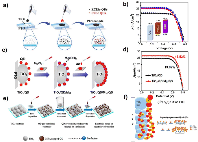 | ||
| Fig. 7 (a) Schematic diagram of the co-sensitization process.36 The figure has been adapted/reproduced from ref. 36 with permission from Wiley, copyright 2018. (b) J–V curves of QDSCs with ZCIS, ZCISe, and ZCISe/ZCIS QDs.38 The figure has been adapted/reproduced from ref. 38 with permission from Wiley, copyright 2019. (c) Schematic diagram of the QD secondary deposition by creating new adsorption sites, and (d) J–V curves of TiO2/QD and TiO2/QD/Mg/QD QDSCs.39 The figure has been adapted/reproduced from ref. 39 with permission from American Chemical Society, copyright 2021. (e) Schematic illustration of the secondary deposition strategy by surfactant-assisted deposition technology.37 The figure has been adapted/reproduced from ref. 37 with permission from American Chemical Society, copyright 2019. (f) Scheme of multilayer sensitizing of TiO2 with QDs by applying negatively charged QDs and positively charged QDs, respectively.99 The figure has been adapted/reproduced from ref. 99 with permission from American Chemical Society, copyright 2012. | ||
The approach of co-sensitization at present can be applied only to load two different types of QDs, so that the remaining QD loading sites can be taken advantage of. Obviously, the loading with the identical narrow band gap of QDs is a better choice to fully utilize incident light. Note that the homogeneous QDs in secondary deposition should respond to the same sites, so necessary measures should be taken to facilitate secondary QD deposition. Zhong's group proposed a convenient QD secondary deposition strategy by creating new adsorption sites via the formation of a metal oxyhydroxide layer without the introduction of new recombination centers.29 During the process of QD deposition, the TiO2 electrodes were first sensitized with MPA-capped ZCISSe QDs via the routine CLIS approach to reach a saturated deposition amount. Then, MgCl2 aqueous solution was pipetted on the QD pre-sensitized TiO2 electrode. The magnesium oxyhydroxide layer formed during the evaporation and drying process of the metal salt solution, which serves as new anchoring sites for the additional loading of QDs (Fig. 7c). The absorption spectrum of the photoanode film shows that an additional 38% of the QDs are immobilized on the photoanode as a single layer. With the increased QD loading amount, not only did the photocurrent increase from 24.23 mA cm−2 to 26.52 mA cm−2 but also the open circuit voltage (0.789 vs. 0.802 V) and the fill factor (0.708 vs. 0.720) significantly improved. Finally, the maximum PCE of the QDSC based on ZCISSe QDs was boosted from 13.82% to 15.52% (Fig. 7d). In CLIS, the colloidal QDs are charged. Therefore, the electric field can serve as a viable driving force to facilitate secondary QD deposition. Wang et al. carried out an electrochemical deposition strategy to sequentially deposit QDs after the CLIS process to increase the QD loading amount.58 The device efficiency of CuInS2 QD-sensitized QDSCs increased from 3.91% to 4.58%. Studies have shown that QDs with positive and negative charges can be alternatively deposited on the surface of TiO2 substrates. Secondary adsorption can also occur when the QD-sensitized photoanodes are modified with molecules with different charges.37,84,99,100 As shown in Fig. 7f, Jin et al. prepared the multilayer of CdSe QDs sensitized TiO2 films using the electrostatic interaction of the oppositely charged QDs. In this article, sulfonate is used as the surface ligand of CdSe QDs for negatively charged QDs and cysteamine for positively charged QDs.89 Li et al. also provided a general surfactant-assisted deposition technology to change the electrostatic force between QDs for increasing QD loading on mesoporous TiO2 films (Fig. 7e). The TiO2 film was first immersed in the MPA-modified QDs aqueous solution to accomplish the primary loading of QDs. Then, the QD pre-sensitized TiO2 films were soaked in the hexadecyltrimethylammonium chloride (HTAC) methanol solution and subsequently in QD aqueous solution to realize secondary QD deposition. It was found that the zeta potential of the pre-sensitized TiO2 film can be effectively adjusted by surfactant treatment, based on which additional QDs are successfully introduced onto photoanodes during secondary deposition. With the help of the surface treatment strategy, various QDs can be successfully introduced onto photoanodes regardless of the nature of the QDs. Accordingly, a certified PCE of 10.26% is demonstrated.37
Conclusion and perspectives
In recent years, researchers have committed to the investigation of deposition methods of QDs for high-loading amounts, which has promoted the rapid development of QDSCs. At present, the PCE of QDSCs has reached over 16%. The increase of QD adsorption capacity effectively improves the light capture capability of the device and inhibits charge recombination loss at photoanode/electrolyte interfaces. Particularly, the development of the CLIS method not only greatly improves the uniform and dense adsorption of QDs on the TiO2 substrates, but also greatly shortens the deposition time of QDs, which provides a way for the cost-effective and easy fabrication of QDSCs. This review article covers the various QD adsorption methods with an emphasis on CLIS. Moreover, effective strategies to boost QD loading are illustrated, and the related QD loading mechanism is analyzed with an emphasis on loading driving forces, resistances, and energy effects. The relations among boosted QD loading amount, device performance, and the related optimized QD loading mechanism are elaborately established. The related information is illuminative for further design and exploration of QDSCs with high loading amounts.Although various effective strategies have been demonstrated, there remains room for further enhancement of QD loading levels, as discussed in the previous section. Further enhancement of QD loading amount not only relies on the excavation of loading driving forces but also should profit from the full occupation of available loading sites by QDs. It is thus inferred simply from geometry that the utilization of batches of QDs with the desired size diversity could be a possible way to take full advantage of loading sites on TiO2 substrates. Besides, there remain challenges in QD loading, especially in terms of the elaborate control of loading behavior. At present, a major obstacle is the occurrence of undesired QD agglomeration at high QD loading levels. Severe QD agglomeration dramatically decreases the collection of photogenerated carriers and undermines device performance. QD agglomeration is triggered by the application of modification reagents and unoptimized QD surfaces that induce too strong interdot interactions. The presence of QD agglomeration restricts the enhancement of effective QD loading driving forces and thus limits available QD loading levels. In order to realize a higher QD loading amount in the future, this issue must be tackled pertinently. Unfortunately, the related understanding of QD agglomeration is rather limited at present. Therefore, advanced characterization should be developed to scrutinize and analyze the QD loading process better so that the related mechanism can be unraveled.
The improvement of PCE allows the QDSCs to take a significant step toward industrial implementation. Nevertheless, there is still a long way to go regarding the scalable deposition technique of QDs, which is also a major factor for QDSCs competing with other established commercial solar cells. In QDSCs, the deposition of QDs is realized by completely immersing the TiO2 substrate in the QD solution, which is the simplest and easiest method among all of the developed QD deposition methods (including blade coating and spray coating).101–103 Furthermore, the scalable deposition technique of QDs is analogous to that of dye sensitized solar cells, which has succeeded in large-area deposition techniques. Consequently, there should be no technical difficulties in the scalable deposition techniques of QDs. In addition, during the process of blade coating and spray coating, the formation of solid QD films will be accompanied by solvent evaporation, which inevitably leads to the shrinkage of the films, thus affecting the uniformity and reproducibility of the film in large-area manufacturing. However, the TiO2 substrate is manufactured by screen printing, which makes it easier to scale up QDSCs than solid-state heterojunction solar cells. Unfortunately, there is still little research on scalable deposition techniques of QDs at present, but this is a main problem that must be considered for the successful industrialization of QDSCs in the future.
Author contributions
Z. Z. and W. W. contributed equally to this work. All authors have approved the final version of the manuscript.Conflicts of interest
The authors declare no competing financial interest.Acknowledgements
This research was supported by the National Natural Science Foundation of China (NFSC, No. U21A20310, 22122805, 22075090, 22278164, and 22308112).Notes and references
- I. Mora-Sero, S. Gimenez, F. Fabregat-Santiago, R. Gomez, Q. Shen, T. Toyoda and J. Bisquert, Acc. Chem. Res., 2009, 42, 1848–1857 CrossRef CAS PubMed.
- P. V. Kamat, K. Tvrdy, D. R. Baker and E. J. Radich, Chem. Rev., 2010, 110, 6664–6688 CrossRef CAS PubMed.
- A. J. Nozik, M. C. Beard, J. M. Luther, M. Law, R. J. Ellingson and J. C. Johnson, Chem. Rev., 2010, 110, 6873–6890 CrossRef CAS PubMed.
- Z. Pan, H. Rao, I. Mora-Seró, J. Bisquert and X. Zhong, Chem. Soc. Rev., 2018, 110, 7659–7702 RSC.
- Z. Du, M. Artemyev, J. Wang and J. Tang, J. Mater. Chem. A, 2019, 7, 2464–2489 RSC.
- S. Lin and X. Peng, Energy Fuels, 2021, 35, 18928–18941 CrossRef CAS.
- Q. Zhao, R. Han, A. R. Marshall, S. Wang, B. M. Wieliczka, J. Ni, J. Zhang, J. Yuan, J. M. Luther, A. Hazarika and G. R. Li, Adv. Mater., 2022, 34, e2107888 CrossRef PubMed.
- S. A. McDonald, G. Konstantatos, S. Zhang, P. W. Cyr, E. J. Klem, L. Levina and E. H. Sargent, Nat. Mater., 2005, 4, 138–142 CrossRef CAS PubMed.
- J. Tang, K. W. Kemp, S. Hoogland, K. S. Jeong, H. Liu, L. Levina, M. Furukawa, X. Wang, R. Debnath, D. Cha, K. W. Chou, A. Fischer, A. Amassian, J. B. Asbury and E. H. Sargent, Nat. Mater., 2011, 10, 765–771 CrossRef CAS PubMed.
- J. Tang, H. Liu, D. Zhitomirsky, S. Hoogland, X. Wang, M. Furukawa, L. Levina and E. H. Sargent, Nano Lett., 2012, 12, 4889–4894 CrossRef CAS PubMed.
- L. Protesescu, S. Yakunin, M. I. Bodnarchuk, F. Krieg, R. Caputo, C. H. Hendon, R. X. Yang, A. Walsh and M. V. Kovalenko, Nano Lett., 2015, 15, 3692–3696 CrossRef CAS PubMed.
- H. Aqoma, S.-H. Lee, I. F. Imran, J.-H. Hwang, S.-H. Lee and S.-Y. Jang, Nat. Energy, 2024 DOI:10.1038/s41560-024-01450-9.
- I. Mora-Seró, Adv. Energy Mater., 2020, 10, 2001774 CrossRef.
- N. Guijarro, T. Lana-Villarreal, I. Mora-Seró, J. Bisquert and R. Gómez, J. Phys. Chem. C, 2009, 113, 4208–4214 CrossRef CAS.
- G. Hodes, J. Phys. Chem. C, 2008, 112, 17778–17787 CrossRef CAS.
- F. Shen, Y. M. Fan, H. Li, S. P. Li, M. Xu and W. B. Dai, J. Alloys Compd., 2022, 922, 166296 CrossRef CAS.
- N. Singh, V. Murugadoss, S. Nemala, S. Mallick and S. Angaiah, Sol. Energy, 2018, 171, 571–579 CrossRef CAS.
- H. Zhang, W. Fang, W. Wang, N. Qian and X. Ji, ACS Appl. Mater. Interfaces, 2019, 11, 6927–6936 CrossRef CAS PubMed.
- H. Zhang, K. Cheng, Y. M. Hou, Z. Fang, Z. X. Pan, W. J. Wu, J. L. Hua and X. H. Zhong, Chem. Commun., 2012, 48, 11235–11237 RSC.
- H. Song, Y. Lin, M. Zhou, H. Rao, Z. Pan and X. Zhong, Angew. Chem., Int. Ed., 2020, 60, 6137–6144 CrossRef PubMed.
- J. Du, Z. Du, J.-S. Hu, Z. Pan, Q. Shen, J. Sun, D. Long, H. Dong, L. Sun, X. Zhong and L.-J. Wan, J. Am. Chem. Soc., 2016, 138, 4201–4209 CrossRef CAS PubMed.
- Z. Pan, I. Mora-Sero, Q. Shen, H. Zhang, Y. Li, K. Zhao, J. Wang, X. Zhong and J. Bisquert, J. Am. Chem. Soc., 2014, 136, 9203–9210 CrossRef CAS PubMed.
- P. K. Santra and P. V. Kamat, J. Am. Chem. Soc., 2012, 134, 2508–2511 CrossRef CAS PubMed.
- W. Peng, J. Du, Z. Pan, N. Nakazawa, J. Sun, Z. Du, G. Shen, J. Yu, J. S. Hu, Q. Shen and X. Zhong, ACS Appl. Mater. Interfaces, 2017, 9, 5328–5336 CrossRef CAS.
- G. Halder, A. Ghosh, S. Parvin and S. Bhattacharyya, Chem. Mater., 2018, 31, 161–170 CrossRef.
- D. Ghosh, A. Ghosh, M. Y. Ali and S. Bhattacharyya, Chem. Mater., 2018, 30, 6071–6081 CrossRef CAS.
- M. A. Basit, M. Aanish Ali, Z. Masroor, Z. Tariq and J. H. Bang, J. Ind. Eng. Chem., 2023, 120, 1–26 CrossRef CAS.
- Y. Sun, G. Jiang, M. Zhou, Z. Pan and X. Zhong, RSC Adv., 2018, 8, 29958–29966 RSC.
- J. Yu, W. Wang, Z. Pan, J. Du, Z. Ren, W. Xue and X. Zhong, J. Mater. Chem. A, 2017, 5, 14124–14133 RSC.
- G. Jiang, Z. Pan, Z. Ren, J. Du, C. Yang, W. Wang and X. Zhong, J. Mater. Chem. A, 2016, 4, 11416–11421 RSC.
- Z. Du, Z. Pan, F. Fabregat-Santiago, K. Zhao, D. Long, H. Zhang, Y. Zhao, X. Zhong, J.-S. Yu and J. Bisquert, J. Phys. Chem. Lett., 2016, 7, 3103–3111 CrossRef CAS PubMed.
- S. Jiao, J. Du, Z. Du, D. Long, W. Jiang, Z. Pan, Y. Li and X. Zhong, J. Phys. Chem. Lett., 2017, 8, 559–564 CrossRef CAS PubMed.
- W. Li, G. Long, Q. Chen and Q. Zhong, J. Power Sources, 2019, 430, 95–103 CrossRef CAS.
- Y. Lin, H. Song, H. Rao, Z. Du, Z. Pan and X. Zhong, J. Phys. Chem. Lett., 2019, 10, 4974–4979 CrossRef CAS PubMed.
- Z. Zhang, H. Song, W. Wang, H. Rao, Y. Fang, Z. Pan and X. Zhong, ACS Energy Lett., 2022, 8, 647–656 CrossRef.
- W. Wang, W. Feng, J. Du, W. Xue, L. Zhang, L. Zhao, Y. Li and X. Zhong, Adv. Mater., 2018, 30, 1705746 CrossRef.
- W. Wang, L. Zhao, Y. Wang, W. Xue, F. He, Y. Xie and Y. Li, J. Am. Chem. Soc., 2019, 141, 4300–4307 CrossRef CAS PubMed.
- Z. Pan, L. Yue, H. Rao, J. Zhang, X. Zhong, Z. Zhu and A. K. Y. Jen, Adv. Mater., 2019, 31, 1903696 CrossRef CAS PubMed.
- H. Song, Y. Lin, Z. Zhang, H. Rao, W. Wang, Y. Fang, Z. Pan and X. Zhong, J. Am. Chem. Soc., 2021, 143, 4790–4800 CrossRef CAS PubMed.
- W. Shockley and H. J. Queisser, J. Appl. Phys., 1961, 32, 510–519 CrossRef CAS.
- W. Li and X. Zhong, J. Phys. Chem. Lett., 2015, 6, 796–806 CrossRef CAS PubMed.
- Y.-L. Lee and Y.-S. Lo, Adv. Funct. Mater., 2009, 19, 604–609 CrossRef.
- Q. Zhang, X. Guo, X. Huang, S. Huang, D. Li, Y. Luo, Q. Shen, T. Toyoda and Q. Meng, Phys. Chem. Chem. Phys., 2011, 13, 4659–4667 RSC.
- S. Hotchandani and P. V. Kamat, J. Phys. Chem., 1992, 96, 6834–6839 CrossRef CAS.
- K. Yan, W. Chen and S. Yang, J. Phys. Chem. C, 2012, 117, 92–99 CrossRef.
- B. B. Jin, X. J. Liu, L. C. Dong, X. X. Zhong, M. Y. Liang, J. Gan, M. Chen and F. Guo, Sol. Energy Mater. Sol. Cells, 2023, 255, 112293 CrossRef CAS.
- M. Sotodeian and M. Marandi, Sol. Energy, 2021, 221, 418–432 CrossRef CAS.
- K. E. Roelofs, S. M. Herron and S. F. Bent, ACS Nano, 2015, 9, 8321–8334 CrossRef CAS PubMed.
- N. Fuke, L. B. Hoch, A. Y. Koposov, V. W. Manner, D. J. Werder, A. Fukui, N. Koide, H. Katayama and M. Sykora, ACS Nano, 2010, 4, 6377–6386 CrossRef CAS PubMed.
- J. Albero, J. N. Clifford and E. Palomares, Coord. Chem. Rev., 2014, 263–264, 53–64 CrossRef CAS.
- M. N. Ishak, K. A. Yaacob and A. F. M. Noor, J. Aust. Ceram. Soc., 2022, 58, 1183–1198 CrossRef CAS.
- A. Singh, N. J. English and K. M. Ryan, J. Phys. Chem. B, 2013, 117, 1608–1615 CrossRef CAS PubMed.
- N. Sato, M. Kawachi, K. Noto, N. Yoshimoto and M. Yoshizawa, Phys. C: Supercond., 2001, 357–360, 1019–1022 CrossRef CAS.
- R. N. Basu, C. A. Randall and M. J. Mayo, J. Am. Ceram. Soc., 2001, 84, 33–40 CrossRef CAS.
- G. Niu, L. Wang, R. Gao, W. Li, X. Guo, H. Dong and Y. Qiu, Phys. Chem. Chem. Phys., 2013, 15, 19595–19600 RSC.
- J. H. Bang and P. V. Kamat, ACS Nano, 2009, 3, 1467–1476 CrossRef CAS PubMed.
- P. Brown and P. V. Kamat, J. Am. Chem. Soc., 2008, 130, 8890–8891 CrossRef CAS.
- M. Wang, Z. Peng, D. Huang, Z. Ning, J. Chen, W. Li and J. Chen, Mater. Sci. Semicond. Process., 2022, 137, 106219 CrossRef CAS.
- J. Tang, H. Birkedal, E. W. McFarland and G. D. Stucky, Chem. Commun., 2003, 18, 2278–2279 RSC.
- R. Kottayi, P. Panneerselvam, N. Singh, V. Murugadoss, R. Sittaramane and S. Angaiah, New J. Chem., 2020, 44, 13148–13156 RSC.
- B. R. Hyun, A. C. Bartnik, L. Sun, T. Hanrath and F. W. Wise, Nano Lett., 2011, 11, 2126–2132 CrossRef CAS PubMed.
- D. Zhang, S. Zhang, Y. Fang, D. Xie, X. Zhou and Y. Lin, Electrochim. Acta, 2021, 367, 137452 CrossRef CAS.
- S. Krüger, S. G. Hickey, S. Tscharntke and A. Eychmüller, J. Phys. Chem. C, 2011, 115, 13047–13055 CrossRef.
- D. Zhang, P. Ma, S. Wang, M. Xia, S. Zhang, D. Xie, X. Zhou and Y. Lin, Appl. Surf. Sci., 2019, 475, 813–819 CrossRef CAS.
- L.-W. Chong, H.-T. Chien and Y.-L. Lee, J. Power Sources, 2010, 195, 5109–5113 CrossRef CAS.
- L. Liu, X. Guo, Y. Li and X. Zhong, Inorg. Chem., 2010, 49, 3768–3775 CrossRef CAS PubMed.
- G. H. Carey, A. L. Abdelhady, Z. Ning, S. M. Thon, O. M. Bakr and E. H. Sargent, Chem. Rev., 2015, 115, 12732–12763 CrossRef CAS PubMed.
- Y. Shen, M. Abolhasani, Y. Chen, L. Xie, L. Yang, C. W. Coley, M. G. Bawendi and K. F. Jensen, Angew. Chem., Int. Ed., 2017, 56, 16333–16337 CrossRef CAS PubMed.
- J. B. Sambur, S. C. Riha, D. Choi and B. A. Parkinson, Langmuir, 2010, 26, 4839–4847 CrossRef CAS PubMed.
- W. Wang, M. Zhang, Z. Pan, G. M. Biesold, S. Liang, H. Rao, Z. Lin and X. Zhong, Chem. Rev., 2021, 122, 4091–4162 CrossRef.
- A. Salant, M. Shalom, I. Hod, A. Faust, A. Zaban and U. Banin, ACS Nano, 2010, 4, 5962–5968 CrossRef CAS PubMed.
- H. Wang, C. Luan, X. Xu, S. V. Kershaw and A. L. Rogach, J. Phys. Chem. C, 2012, 116, 484–489 CrossRef CAS.
- J. Chen, D. W. Zhao, J. L. Song, X. W. Sun, W. Q. Deng, X. W. Liu and W. Lei, Electrochem. Commun., 2009, 11, 2265–2267 CrossRef CAS.
- S. Choi, H. Jin and S. Kim, J. Phys. Chem. C, 2014, 118, 17019–17027 CrossRef CAS.
- A. Nag, M. V. Kovalenko, J.-S. Lee, W. Liu, B. Spokoyny and D. V. Talapin, J. Am. Chem. Soc., 2011, 133, 10612–10620 CrossRef CAS PubMed.
- M. V. Kovalenko, M. Scheele and D. V. Talapin, Science, 2009, 324, 1417–1420 CrossRef CAS PubMed.
- C. K. Lee and C. C. Hua, J. Chem. Phys., 2010, 132, 224904 CrossRef PubMed.
- M. A. Boles, D. Ling, T. Hyeon and D. V. Talapin, Nat. Mater., 2016, 15, 364 CrossRef CAS PubMed.
- W. Wang, J. Du, Z. Ren, W. Peng, Z. Pan and X. Zhong, ACS Appl. Mater. Interfaces, 2016, 8, 31006–31015 CrossRef CAS.
- X. Meng, J. Du, H. Zhang and X. Zhong, RSC Adv., 2015, 5, 86023–86030 RSC.
- Y. Liang, J. E. Thorne and B. A. Parkinson, Langmuir, 2012, 28, 11072–11077 CrossRef CAS PubMed.
- W. Wang, Y. Xie, F. He, Y. Wang, W. Xue and Y. Li, Green Energy Environ., 2023, 8, 213–223 CrossRef CAS.
- B. B. Jin, S. Y. Kong, G. Q. Zhang, X. Q. Chen, H. S. Ni, F. Zhang, D. J. Wang and J. H. Zeng, J. Colloid Interface Sci., 2021, 586, 640–646 CrossRef CAS PubMed.
- S. Choi, H. Jin, J. Bang and S. Kim, J. Phys. Chem. Lett., 2012, 3, 3442–3447 CrossRef CAS PubMed.
- J. Aldana, N. Lavelle, Y. Wang and X. Peng, J. Am. Chem. Soc., 2005, 127, 2496–2504 CrossRef CAS PubMed.
- D. Gumy, C. Morais, P. Bowen, C. Pulgarin, S. Giraldo, R. Hajdu and J. Kiwi, Appl. Catal., B, 2006, 63, 76–84 CrossRef CAS.
- I.-R. Jo, Y.-H. Lee, H. Kim and K.-S. Ahn, J. Alloys Compd., 2021, 870, 159527 CrossRef CAS.
- K. Lu, Y. Wang, Z. Liu, L. Han, G. Shi, H. Fang, J. Chen, X. Ye, S. Chen, F. Yang, A. G. Shulga, T. Wu, M. Gu, S. Zhou, J. Fan, M. A. Loi and W. Ma, Adv. Mater., 2018, 30, 1707572 CrossRef PubMed.
- M. Gu, Y. Wang, F. Yang, K. Lu, Y. Xue, T. Wu, H. Fang, S. Zhou, Y. Zhang, X. Ling, Y. Xu, F. Li, J. Yuan, M. A. Loi, Z. Liu and W. Ma, J. Mater. Chem. A, 2019, 7, 15951–15959 RSC.
- A. R. Kirmani, G. Walters, T. Kim, E. H. Sargent and A. Amassian, ACS Appl. Energy Mater., 2020, 3, 5385–5392 CrossRef CAS.
- J. Yang, T. Oshima, W. Yindeesuk, Z. Pan, X. Zhong and Q. Shen, J. Mater. Chem. A, 2014, 2, 20882–20888 RSC.
- J. Du, R. Singh, I. Fedin, A. S. Fuhr and V. I. Klimov, Nat. Energy, 2020, 5, 409–417 CrossRef CAS.
- J. Huang, B. Xu, C. Yuan, H. Chen, J. Sun, L. Sun and H. Agren, ACS Appl. Mater. Interfaces, 2014, 6, 18808–18815 CrossRef CAS PubMed.
- Z. Ren, J. Yu, Z. Pan, J. Wang and X. Zhong, ACS Appl. Mater. Interfaces, 2017, 9, 18936–18944 CrossRef CAS PubMed.
- A. Shrestha, M. Batmunkh, A. Tricoli, S. Z. Qiao and S. Dai, Angew. Chem., Int. Ed., 2019, 58, 5202–5224 CrossRef CAS PubMed.
- R. G. Pearson, J. Am. Chem. Soc., 1969, 85, 3533–3539 CrossRef.
- R. G. Parr and R. G. Pearson, J. Am. Chem. Soc., 1983, 105, 7512–7516 CrossRef CAS.
- H. Song, H. Mu, J. Yuan, B. Liu, G. Bai and S. Lin, SusMat, 2023, 3, 543–554 CrossRef CAS.
- H. Jin, S. Choi, R. Velu, S. Kim and H. J. Lee, Langmuir, 2012, 28, 5417–5426 CrossRef CAS PubMed.
- H. Jin, J. Nam, J. Park, S. Jung, K. Im, J. Hur, J.-J. Park, J.-M. Kim and S. Kim, Chem. Commun., 2011, 47, 1758–1760 RSC.
- A. R. Kirmani, A. D. Sheikh, M. R. Niazi, M. A. Haque, M. Liu, F. P. G. de Arquer, J. Xu, B. Sun, O. Voznyy, N. Gasparini, D. Baran, T. Wu, E. H. Sargent and A. Amassian, Adv. Mater., 2018, 30, 1801661 CrossRef PubMed.
- J. Yuan, C. Bi, S. Wang, R. Guo, T. Shen, L. Zhang and J. Tian, Adv. Funct. Mater., 2019, 29, 1906615 CrossRef CAS.
- N. Sukharevska, D. Bederak, V. M. Goossens, J. Momand, H. Duim, D. N. Dirin, M. V. Kovalenko, B. J. Kooi and M. A. Loi, ACS Appl. Mater. Interfaces, 2021, 13, 5195–5207 CrossRef CAS PubMed.
Footnote |
| † These authors contributed to this work equally. |
| This journal is © The Royal Society of Chemistry 2024 |

