
 Open Access Article
 This Open Access Article is licensed under a Creative Commons Attribution-Non Commercial 3.0 Unported Licence
Identifying the active sites and intermediates on copper surfaces for electrochemical nitrate reduction to ammonia†
Yohan
Kim‡
 a,
Jinyoung
Ko‡
bc,
Minyoung
Shim
a,
Jiwon
Park
a,
Hyun-Hang
Shin
d,
Zee Hwan
Kim
d,
Yousung
Jung
*bc and
Hye Ryung
Byon
*a
a,
Jinyoung
Ko‡
bc,
Minyoung
Shim
a,
Jiwon
Park
a,
Hyun-Hang
Shin
d,
Zee Hwan
Kim
d,
Yousung
Jung
*bc and
Hye Ryung
Byon
*a
aDepartment of Chemistry, Korea Advanced Institute of Science and Technology (KAIST), 291, Daehak-ro, Yuseong-gu, Daejeon 34141, Republic of Korea. E-mail: hrbyon@kaist.ac.kr
bDepartment of Chemical and Biomolecular Engineering, Korea Advanced Institute of Science and Technology (KAIST), 291 Daehak-ro, Yuseong-gu, Daejeon 34141, Republic of Korea
cSchool of Chemical and Biological Engineering, Seoul National University, Seoul 08826, Republic of Korea. E-mail: yousung.jung@snu.ac.kr
dDepartment of Chemistry, Seoul National University, Seoul 08826, Republic of Korea
First published on 12th January 2024
Abstract
Copper (Cu) is a widely used catalyst for the nitrate reduction reaction (NO3RR), but its susceptibility to surface oxidation and complex electrochemical conditions hinders the identification of active sites. Here, we employed electropolished metallic Cu with a predominant (100) surface and compared it to native oxide-covered Cu. The electropolished Cu surface rapidly oxidized after exposure to either air or electrolyte solutions. However, this oxide was reduced below 0.1 V vs. RHE, thus returning to the metallic Cu before NO3RR. It was distinguished from the native oxide on Cu, which remained during NO3RR. Fast NO3− and NO reduction on the metallic Cu delivered 91.5 ± 3.7% faradaic efficiency for NH3 at −0.4 V vs. RHE. In contrast, the native oxide on Cu formed undesired products and low NH3 yield. Operando shell-isolated nanoparticle-enhanced Raman spectroscopy (SHINERS) analysis revealed the adsorbed NO3−, NO2, and NO species on the electropolished Cu as the intermediates of NH3. Low overpotential NO3− and NO adsorptions and favorable NO reduction are key to increased NH3 productivity over Cu samples, which was consistent with the DFT calculation on Cu(100).
1. Introduction
Ammonia (NH3) is imperative for agricultural fertilizers and hydrogen-carrying fuel.1–3 However, the excessive use of artificial fertilizer has disrupted the nitrogen cycle, causing nitrates (NO3−) to drain into groundwater and rivers, and nitrous oxide (N2O) emissions.4–6 There is growing interest in using reactive nitrogen pollutants as an NH3 source to address environmental concerns and explore clean energy alternatives. Electrochemical NO3− reduction reaction (NO3RR) in water is the representative method, offering additional advantages over the Haber–Bosch process in terms of mild reaction conditions (room temperature, atmospheric pressure, and no need for natural gas feedstock),7–12 and outperforming electrochemical N2 reduction in kinetics.13–15NO3RR involves eight electron-transfer processes with a thermodynamic reduction potential (E0) of +0.69 V vs. the reversible hydrogen electrode (RHE).16–18
| NO3− + 9H+ + 8e− → NH3 + 3H2O E0 = 0.69 V vs. RHE |
Computational simulations envisioned a sequential deoxygenation process from NO3− to nitric oxide (*NO, where the asterisk symbol indicates surface adsorption of the species) or nitride (*N), followed by hydrogenation to yield NH3.18–20 Two key steps determine activity and selectivity; (i) the initial NO3− reduction to nitrite (*NO2) is the rate-determining step. The sluggish process caused significant onset overpotential.21,22 (ii) The *NO binding strength on the catalyst significantly impacts selective NH3 production. Weak NO adsorption leads to NO dissolution or NO–NO coupling, yielding NO, N2O, NH2OH, or N2 byproducts.17,18,21–24
Various catalysts have been investigated to optimize *NO3− and *NO adsorption. Copper (Cu) emerges as the most economical choice in addition to its ability to create a significant potential gap between NO3− reduction and hydrogen evolution reaction (HER). Both Cu(111)25–28 and (100) facets9,29 exhibited reasonable activity in overall processes, and their performance was further enhanced when forming alloys or bimetallic structures with Ru, Rh, Pd, or Ir.11,30–34 However, the vulnerable nature of the Cu surface has posed challenges in identifying the actual active sites and their roles; the metallic Cu undergoes quick oxidation in the air or an electrolyte solution. Conversely, the Cu oxides are electrochemically reduced. However, degrees of oxidation and reduction vary depending on the conditions and have not been easily controlled. For instance, CuO nanostructures transformed into Cu/Cu2O heterostructures through in situ reduction.12 Although the heterostructure showed better NH3 productivity, identifying the true active sites has proven difficult due to the presence of defect/strain structures with varying surface roughnesses9,35–37 and the complexity of valence states at Cu/Cu2O sites.38
Here, we focused on the Cu surface states that are essential as the active sites to determine NO3RR activity and selectivity. Three surface states of Cu foil were prepared, representing the native oxide-covered Cu, partially etched native oxide, and metallic Cu surface with a predominant (100) facet. It was found that the metallic Cu surface was oxidized by air or electrolyte solution. However, this oxide layer was rapidly eliminated below 0.1 V vs. RHE (before starting NO3RR). The reverted metallic Cu surface facilitated NO3− and NO reductions and offered 91.5 ± 3.7% of NH3 faradaic efficiency at −0.4 V vs. RHE. In contrast, native oxide on Cu was not fully removed under the same electrochemical condition, providing inferior NH3 productivity. Operando Raman spectroscopy analysis revealed *NO3−, *NO2, and *NO species on metallic Cu as the intermediates of NH3. Subsequent reductions of *NO3− and *NO are associated with NH3 productivity, which is further supported by the DFT calculation. In contrast, the native oxide on Cu did not clearly show these intermediates and appeared *NO with higher overpotential.
2. Results and discussion
We prepared three types of Cu foils using different surface treatments (Scheme S1 and Experimental details in ESI†). First, as-received Cu foil was washed with acetone, isopropanol, and de-ionized (DI) water sequentially using bath sonication for 5 min each. The resulting Cu foil was named w-Cu. The second and third methods eliminated the native oxide layer of w-Cu.39,40 The w-Cu was soaked in glacial acetic acid for 5 min,41 which was indicated as a-Cu. Separately, w-Cu was electrochemically polished by applying 2 V for 5 min in 85 wt% H3PO4 solution,42,43 denoted as e-Cu. All these treatments were conducted just before surface characterizations or NO3RR tests.The as-received Cu surface state and morphology remained intact in w-Cu (Fig. 1a). Scanning electron microscope (SEM) and atomic force microscope (AFM) displayed stripe patterns on the Cu surface, attributed to root-mean-square (RMS) roughness at 14.4 nm in 100 μm2 area. While a-Cu had a similar surface pattern, a surface RMS increased to 25.4 nm (Fig. 1b). It indicated non-uniform and incomplete surface etching. Electron backscatter diffraction (EBSD) analysis revealed a prevalent Cu(100) facet (red) over both w-Cu and a-Cu surfaces, while various polycrystals also appeared with small domains. Chemical analyses using Auger spectra (Fig. 1) and X-ray photoelectron spectroscopy (XPS, Fig. S1†) showed intense Cu+ and Cu2+ signals for both samples, i.e., the presence of Cu2O and CuO.44 Quantitatively, the surface of w-Cu was covered by 81% Cu+ and 21% Cu2+ (Fig. S2†). There were no metallic Cu0 present in the Cu Auger spectra. In comparison, a-Cu had a partially metallic Cu surface (37%) due to etching, although the major species was Cu+ (63%). Native Cu oxide on w-Cu was further analysed using cross-sectional transmission electron microscopy (TEM), exhibiting CuO(111) and (002) with 0.23 and 0.25 nm d-spacings, respectively (Fig. 2a). The thicknesses were varied from 2 to 40 nm in multiple areas (Fig. 2b).
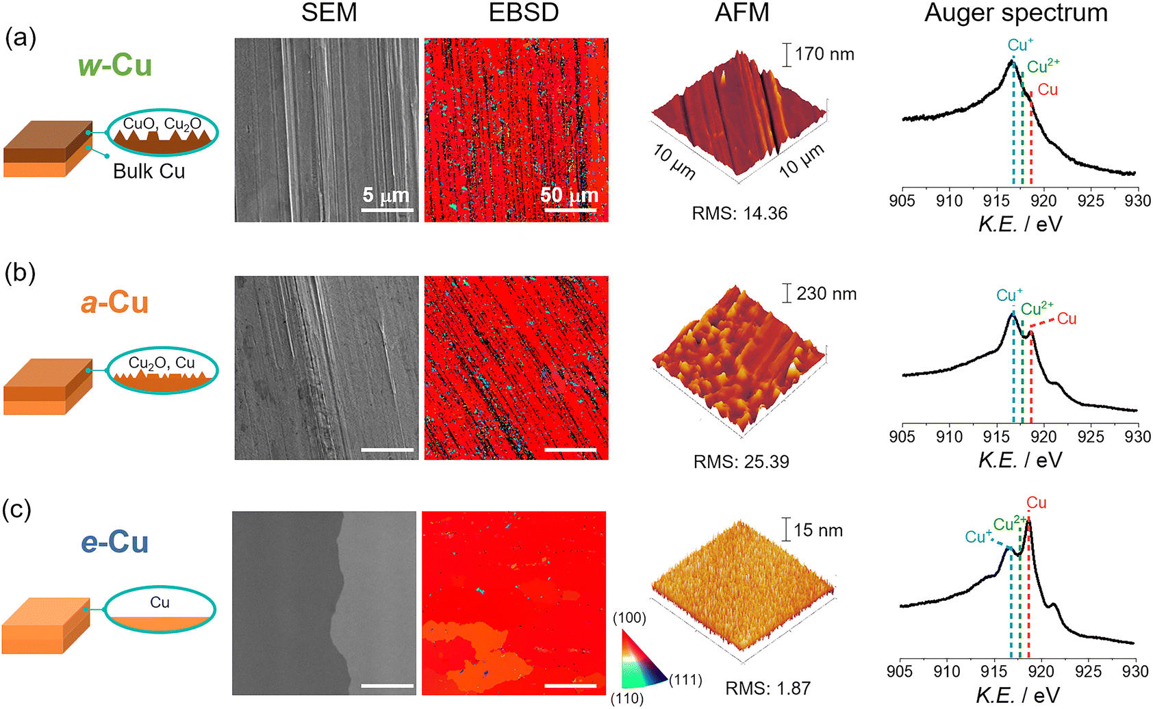 | ||
| Fig. 1 Surface characteristics of Cu electrodes with different surface treatments through (a) solvent washing (top panel, w-Cu), (b) acid-etching (middle panel, a-Cu), and (c) electropolishing (bottom panel, e-Cu). Analyses of each sample showed schematic illustration, SEM image, electron backscatter diffraction (EBSD) image with a color indicator (right bottom), AFM image, and Auger Cu LMM spectrum (from the left to the right side). All scale bars in SEM and EBSD indicate 5 μm and 50 μm, respectively. RMS stands for root-mean-square roughness with nanometer unit. Dashed lines in Auger spectra indicate Cu+ (916.8 eV), Cu2+ (917.7 eV), and Cu0 (918.6 eV). | ||
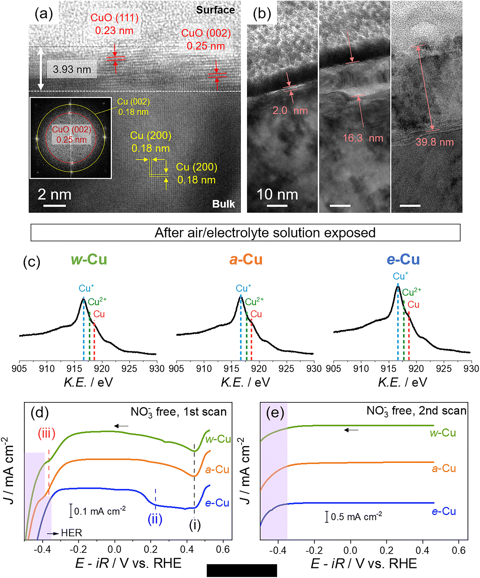 | ||
| Fig. 2 Characteristics of native oxide on Cu foils and after air/electrolyte solution oxidation. (a and b) Cross-sectional TEM images of w-Cu in multiple areas, prepared by focused ion beam (FIB) milling. (a) d-spacing of CuO from native oxide and Cu(200) and corresponding FFT image (inset) (b) varied native oxide thicknesses of w-Cu. (c) Auger Cu LMM spectra of Cu foils after exposure to air and Ar-saturated 1 M KOH solution. (d and e) Cathodic linear sweep voltammogram (LSV) profiles of Cu foils in Ar-saturated 1 M KOH solutions. Potentials were swept from open circuit potential (0.53 V) for (d) the initial and (e) the second scan at a rate of 5 mV s−1. The violet regions indicate hydrogen evolution reaction (HER). | ||
In contrast, e-Cu had a stripe-free and even surface with Cu(100) facet (RMS: 1.9 nm, Fig. 1c). Auger and XPS analyses identified the prevalent metallic Cu0 (71% coverage) on the surface, demonstrating the complete elimination of the oxide layer (Fig. S1 and S2†).
Three types of Cu foils were susceptible to oxidation when electrochemical cells were assembled in ambient air and stabilized in an electrolyte solution. Thus, the actual surface states before NO3RR tests should be identified. We analysed Cu surfaces after air-tight H-cell installation (details in Fig. S3†) and argon (Ar) gas purge into 1 M KOH solution for 10 min. Auger spectra revealed a growing Cu+ signal on e-Cu and a-Cu compared to a negligible change on w-Cu (Fig. 2c), indicating immediate oxidation arising from the metallic Cu sites. We also note that residual organic contaminants appearing on w-Cu were removed by soaking in the KOH solution (Fig. S1 and S4†).
However, the instantly oxidized Cu differs from the native oxide; the former was rapidly removed before or during the initial NO3RR tests. We tracked different reduction potentials of these oxide layers in 1 M KOH solution. Cathodic linear sweep voltammetry (LSV) in Fig. 2d shows three potential regions: (i) 0.4–0.5 V (vs. RHE unless otherwise stated), (ii) 0.1–0.4 V, and (iii) −0.25–−0.45 V. The (i) includes the CuO reduction to Cu2O, and the (ii) and (ii) regions indicate Cu(OH)2/Cu2O reduction to Cu0.45–47 The cathodic signal of CuO was developed in (i) for all samples. However, the Cu(OH)2/Cu2O reduction in the (ii) region was applied for e-Cu only. With higher overpotentials (close to HER), the Cu+ reduction appeared for a-Cu and w-Cu, but not e-Cu, as shown in (iii) region.46,48–50 The appearance of the cathodic peaks in (iii) is, therefore, likely due to the thick native oxide (up to 40 nm).45,46,48,49,51 During the second LSV scan, all oxide/hydroxide signals vanished (Fig. 2e). It indicates that the metallic Cu surface was recovered on e-Cu below 0.1 V, whereas the native oxide was reduced to below −0.4 V.
Next, NO3RRs were examined with 50 mM KNO3. Cathodic LSVs showed two waves for e-Cu and three for a-Cu and w-Cu (Fig. 3a–c). The initial (c1) and second waves (c2) appeared for all Cu foils, while the third one (c3) at higher overpotentials only emerged for a-Cu and w-Cu (Fig. 3a–c). To identify each signal, NO2− or NO, which are key intermediates in NO3RR, was added to a 1 M KOH solution without NO3−.29 Adding 50 mM NaNO2 vanished the c1 wave, identifying c1 to the NO3− reduction to NO2/NO2−. NO gas was generated by Cu powder and neat nitric acid (HNO3) reaction and introduced to the electrochemical cell through the Ar stream (Scheme S2†).52 Emerging NO cathodic waves notably relied on the Cu surfaces; the metallic Cu on e-Cu promoted the NO reduction at c2 (−0.02 V) with a significant current density (J), whereas the native Cu oxide of w-Cu reduced NO at c3 (−0.31 V). The a-Cu allowed both c2 (−0.10 V) and c3 (−0.28 V) due to the coexistence of both metallic Cu and Cu oxide.21 Consequently, metallic Cu offered more active sites for prompt NO reduction and caused the absence of c3.
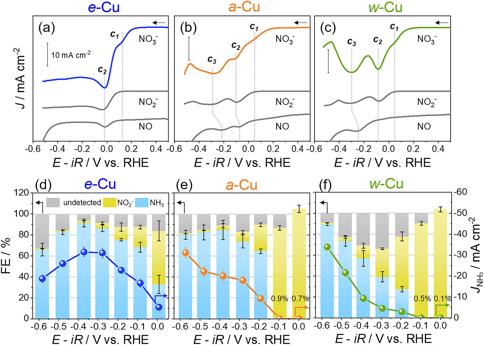 | ||
| Fig. 3 Electrochemical NO3RR for Cu foils in Ar-saturated 1 M KOH solutions with 50 mM KNO3. (a–c) Cathodic LSVs for (a) e-Cu, (b) a-Cu, and (c) w-Cu at a scan rate of 5 mV s−1. The c1–c3 indicate cathodic waves, and all scale bar indicates 10 mA cm−2. NO2− and NO curves (gray) were acquired from 50 mM NaNO2 and NO gas, respectively, instead of NO3−. (d–f) Potential-dependent faradaic efficiency (FE, bar graphs with the left y-axis) of NH3 (sky blue), NO2− (pale yellow), and undetected products (gray) by colorimetric analyses for (d) e-Cu, (e) a-Cu, and (f) w-Cu. The partial current density of NH3 (JNH3) is indicated as dots with the right y-axis. | ||
For the potential aspect, e-Cu offered more positive (i.e., lower overpotentials) for c1 (>100 mV) and c2 (>50 mV) compared to those for a-Cu and w-Cu (Table 1). The rate-determining NO3− reduction to NO2− was significantly catalysed by the metallic Cu and improved overall reaction kinetics. Additionally, the Tafel slope of e-Cu was smaller (71.4 mV dec−1) than that of a-Cu and w-Cu (>100 mV dec−1) (Fig. S5†) and even superior to the ones of previously reported Cu-based catalysts (Table S1†).21,38,53–57
| Surface states Auger spectra | Cathodic potentials in LSV (V vs. RHE) | cathodic reactant(s) | FENH3 (%) | Yield rate b (mass yield rate) c | EENH3 (%) | |||||||
|---|---|---|---|---|---|---|---|---|---|---|---|
| c 1 | c 2 | c 3 | 0 V | −0.4 V | −0.4 V | −0.4 V | |||||
| a c 1 potentials were indicated from the 2nd derivatives of LSV curves. b The unit is μmol cm−2 h−1. c The unit is mg cm−2 h−1. | |||||||||||
| e-Cu | Cu0 (71%) | 0.15 | NO3− | −0.02 | NO2−, NO | NA | — | 41.6 | 91.5 | 143.1 (2.43) | 30.8 |
| a-Cu | Cu+ (63%) | 0.05 | −0.10 | NO2−, NO | −0.28 | NO | 0.7 | 84.8 | 95.5 (1.62) | 28.4 | |
| w-Cu | Cu+ (81%) | 0.03 | −0.08 | NO2− | −0.31 | NO | 0.1 | 56.9 | 43.8 (0.75) | 19.0 | |
Furthermore, the active sites on e-Cu were stable. Cyclic voltammograms (CVs) exhibited constant NO-reducing waves during three cycles, although sample surfaces were roughened during NO3RR (Fig. S6 and S7†). To depict electrochemical active surface area (ECSA), we estimated the roughness factors from two methods: the RMS surface roughness from the AFM measurement and the electric double layer capacitance (EDLC) relative to the specific capacitance, as shown in Table S2 and S3.† Both methods consistently resulted in the lowest roughness factor and ECSA for the as-prepared e-Cu. During NO3RR, the EDLC of e-Cu increased more than a-Cu and w-Cu (Fig. S8a†). However, the geometric-area-normalized current densities were constant during CV cycling (Fig. S6†). In addition, e-Cu still exhibited the highest ECSA-normalized current density in the fourth cycled CV (Fig. S8 and Table S3†). It corroborated the stable and preserved active sites on e-Cu regardless of the increased surface roughness.
The selectivity and yield of NH3 production was assessed by chronoamperometry (CA) tests and colorimetric analyses of the electrolyte solution (NO2− and NH3 detection, Fig. S9–S11†).12,18,21 For e-Cu, faradaic efficiency of NH3 (FENH3) was 41.6% at 0.0 V and maximized to 91.5% at −0.4 V during 1 h reaction (Fig. 3d). Isotope labeling tests demonstrated that NO3− was the exclusive N source to form NH3 (Fig. S12†). Declining FENH3 below −0.4 V was attributed to HER included in the increased undetected species. By comparison, w-Cu and a-Cu generated <1% FENH3 at 0.0 V, where NO2− was the primary product (Fig. 3e and f). A very small current density hindered a precise quantification (>100% FE), and this result is explained by an insignificant current density at c1 in the LSV (Fig. 2b and c). High charge-transfer resistances obtained at 0.0 V and −0.1 V also illustrated sluggish NO3− reduction on the native Cu oxide (Fig. S13†). At −0.4 V, although FENH3 was developed to 84.8% (a-Cu) and 56.9% (w-Cu), the efficiency was still inferior to e-Cu. We also found that the undetected species became the maximum at −0.3 V from w-Cu and decreased toward the negative potential, distinct from the e-Cu trend (Fig. 3f). Undesired products, such as N2O, NH2OH, and N2, were produced from w-Cu (Fig. S14†) due to weak *NO adsorption on the native oxide.58,59 A subsequent decline of undetected species indicated a slow HER from the oxide layer that was not wholly eliminated during NO3RR. The a-Cu showed an in-between tendency as existing both Cu0 and native oxide (Fig. 3e). Still, the contribution of metallic Cu for FENH3 was notable at −0.2–−0.4 V. As a result, e-Cu showed an excellent NH3 yield rate and half-cell energy efficiency (Table 1 and Fig. S15†), verifying the best NH3 selectivity.
To further shed light on the NO3RR process, e-Cu and w-Cu surfaces were observed by operando electrochemical shell-isolated nanoparticle-enhanced Raman spectroscopy (SHINERS) using Au@SiO2 nanoparticles and Nafion binder (Fig. 4a, S16 and S17, and details in ESI†). Spectra of as-prepared e-Cu and w-Cu surfaces showed peaks of Cu2O (430 cm−1), Cu(OH)x (489 cm−1), and CuO (630 cm−1) (the left panel of Fig. 4b, c and Table S4†). However, the oxide/hydroxide peaks from e-Cu weakened at 0.0–−0.2 V, validating a recovery of the metallic Cu surface during NO3RR (Fig. S18†). The trend is more evident when comparing peak-height intensity with potential change, as shown in Fig. S18.† During NO3RR, e-Cu showed that the peaks of Cu(OH)x and CuO were almost completely absent, while Cu2O species exhibited a relatively small decrease. In sharp contrast, w-Cu preserved all oxide peaks in 0.0–−0.5 V. At the end of NO3RR, the peaks of Cu oxides remained on w-Cu but not on e-Cu.
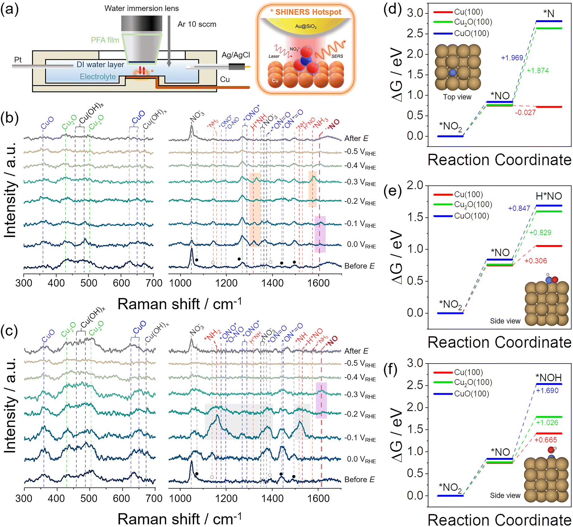 | ||
| Fig. 4 Operando SHINERS analysis for NO3− reduction process on e-Cu and w-Cu electrodes. (a) Schematic illustration of an electrochemical cell. The right scheme illustrates the SERS hotspot defined by the SHIN (Au@SiO2) particle placed on top of the Cu surface undergoing a chemical reaction. (b and c) SERS spectra for (b) e-Cu and (c) w-Cu, before the test, 0.0 V–−0.5 V vs. RHE, and after the test (from bottom to top). The potential was negatively scanned with −100 mV step. Vertical dashed lines indicate vibrational frequencies of CuO, Cu2O, Cu(OH)x, NO3− (black), NO2− (blue), NO (violet), HNO/NH/NH2/NH3 (red). For the details of peak assignment, see Tables S4 and S5.† The orange, violet, and gray box indicate *NH2/*NH3, *NO, and byproduct intermediates, respectively. (d–f) Reaction free energy diagrams of (d) *NO2 → *N, (e) *NO2 → H*NO, and (f) *NO2 → *NOH on Cu(100), Cu2O (100), and CuO(100) at pH = 14, calculated by DFT. The insets showed the optimized structures of three final intermediates adsorbed on Cu(100) (brown, blue, red, and white represent Cu, N, O, and H, respectively). | ||
NO3RR intermediates were observed in 900–1700 cm−1 region (the right panel of Fig. 4b, c and Table S5†), where peaks of Nafion binder and residual citrate used for the synthesis of Au nanoparticles (Fig. S19†) also appeared, marked as ● and ○, respectively. Before applying a potential, a strong symmetric stretching peak of NO3− (νs(NO3−), 1047 cm−1) in the solution emerged. At 0.0 V, this intensity weakened on e-Cu, while asymmetric NO2 of NO3− peak (νas(NO2), 1354 cm−1)60,61 was intensified, possibly due to *NO3− adsorption (the right panel of Fig. 4b). Concurrently, peaks of *NO2 intermediates were observed as the result of NO3− reduction,9,35–37 assigned to νas(*ONO*) (1290 cm−1) and νas(*ON = O) (1367 cm−1). More importantly, the appearance of *NO (1608 cm−1) at 0.0–−0.1 V signified the suitable binding strength with e-Cu and the occurrence of subsequent hydrogenation. It caused the appearance of peaks of *NH2 (δs(H*NH), 1320 cm−1) at 0.0–−0.3 V and growing *NH3 associated δas(H*NH) (1578 cm−1) at −0.3 V. Rapid NH3 production at −0.4 V then attenuated all Raman peak intensities, and HER obscured signals at −0.5 V.
In comparison, w-Cu showed intense peaks of *NO2 (1367 cm−1 of *ON![[double bond, length as m-dash]](https://www.rsc.org/images/entities/char_e001.gif) O and 1450 cm−1 of *ON*O) at 0.0–−0.2 V (the right panel of Fig. 4c). Unlike the e-Cu case, new hydrogenated species emerged, such as δ(NH2) (1160 cm−1) possibly arising from NH2OH,62δ(*NH) (1520 cm−1),62,63 and δ(H*NO) (1534 cm−1), with strong intensities. We presume that they are intermediates of byproducts (N2O, NH2OH, and N2) rather than those of NH3. Meanwhile, *NO had not yet emerged in this potential range, suggesting that the accessible NO is weakly absorbed on w-Cu or reacts undesirably with re-dissolved NO, which was supported by the increased undetected species in Fig. 3f. The apparent *NO peak was observed at −0.3 V, which aligned with the NO reduction potential (c3) in the LSV (Fig. 3c) and the increased FENH3 below −0.3 V (Fig. 3f).
O and 1450 cm−1 of *ON*O) at 0.0–−0.2 V (the right panel of Fig. 4c). Unlike the e-Cu case, new hydrogenated species emerged, such as δ(NH2) (1160 cm−1) possibly arising from NH2OH,62δ(*NH) (1520 cm−1),62,63 and δ(H*NO) (1534 cm−1), with strong intensities. We presume that they are intermediates of byproducts (N2O, NH2OH, and N2) rather than those of NH3. Meanwhile, *NO had not yet emerged in this potential range, suggesting that the accessible NO is weakly absorbed on w-Cu or reacts undesirably with re-dissolved NO, which was supported by the increased undetected species in Fig. 3f. The apparent *NO peak was observed at −0.3 V, which aligned with the NO reduction potential (c3) in the LSV (Fig. 3c) and the increased FENH3 below −0.3 V (Fig. 3f).
DFT calculations also supported the notable influence of the Cu valence state on *NO2 and *NO reductions using three Cu surface models: Cu(100), Cu2O(100), and CuO(100) (Fig. S20 and Computational details in ESI†). We first examined the formation of *NO from the reduction of *NO2 and calculated Gibbs free energy changes (ΔG) on different Cu surfaces at pH = 14 (Tables S6–S8†). The ΔG value is positive on all Cu surfaces, implying a thermodynamically energy-consuming reduction process. However, each surface has only a small difference in ΔG, around 0.75 eV.
Subsequent reduction of *NO through the ΔG was calculated. Simulated intermediates were suggested as *N, H*NO, and *NOH,11,18,64,65 which are different in deoxygenation, hydrogenation, and final product determination steps.65–67Fig. 4d–f shows each intermediate's Gibbs free energy diagrams on Cu surfaces at pH = 14. The optimized structures of three intermediates adsorbed on each surface were presented in the inset and Fig. S21–S23.† The Cu(100) surface had the most favourable ΔG value of −0.027 eV for forming *N from *NO. In comparison, the other oxide surfaces had significantly large positive values (>1.8 eV) due to the thermodynamic barrier toward *N, which was suggested to be a highly NH3-selective intermediate.65 The ΔG for the formation of H*NO and *NOH are also calculated through *NO reduction. Cu2O(100) and CuO(100) surfaces showed the lowest ΔG for H*NO compared to *N and *NOH, consistent with the appearance of H*NO species in the Raman spectrum at −0.1–−0.2 V (Fig. 4c). Nonetheless, the energy barrier for H*NO and *NOH formation with *NO reduction was lower at the Cu(100) surface than at Cu oxides. It suggests that all intermediates from the *NO reduction can be produced more easily on the metallic Cu surface, consistent with the available experimental results.
3. Conclusions
In summary, we studied Cu surface states for NO3RR activity and selectivity. The native oxide layer on Cu involved slow NO3− and NO reduction and produced undesired products. In contrast, metallic Cu with an even surface produced NH3 with better activity and selectivity. Although the metallic Cu was immediately oxidized in air or electrolyte solution, this oxide was rapidly reduced below 0.1 V. Therefore, the metallic Cu0 surface was recovered in contrast to the persistent native oxide. Electrochemical tests, operando Raman spectroscopy, and DFT calculations consistently demonstrated the metallic Cu as the active sites of NO3RR, attributed to suitable *NO3− and *NO adsorptions and following their rapid reductions.Data availability
All data associated with this publication are provided in the ESI.†Author contributions
Y. K. and H. R. B. designed the experiments; Y. K. and M. S. conducted electrochemical experiments; J. K. contributed to DFT calculations on free energy change under the supervision of Y. J.; J. P., H. S, and Z. H. K. advised to setup and interpret SHINERS experiments.; H. S. simulated the Raman peak position of intermediates under the supervision of Z. H. K; Y. K., H. R. B., J. K., and Y. J. wrote the manuscript.Conflicts of interest
There are no conflicts to declare.Acknowledgements
This work was supported by the National Research Foundation of Korea (NRF) grant funded by the Korean government (MSIT) (No. NRF-2019R1A2C2007551 and 2021R1A5A1030054).Notes and references
- J. G. Chen, R. M. Crooks, L. C. Seefeldt, K. L. Bren, R. M. Bullock, M. Y. Darensbourg, P. L. Holland, B. Hoffman, M. J. Janik, A. K. Jones, M. G. Kanatzidis, P. King, K. M. Lancaster, S. V. Lymar, P. Pfromm, W. F. Schneider and R. R. Schrock, Science, 2018, 360, eaar6611 CrossRef PubMed.
- G. Qing, R. Ghazfar, S. T. Jackowski, F. Habibzadeh, M. M. Ashtiani, C. P. Chen, M. R. Smith 3rd and T. W. Hamann, Chem. Rev., 2020, 120, 5437–5516 CrossRef CAS PubMed.
- X. Zhao, G. Hu, G. F. Chen, H. Zhang, S. Zhang and H. Wang, Adv. Mater., 2021, 33, e2007650 CrossRef PubMed.
- D. E. Canfield, A. N. Glazer and P. G. Falkowski, Science, 2010, 330, 192–196 CrossRef CAS PubMed.
- N. Gruber and J. N. Galloway, Nature, 2008, 451, 293–296 CrossRef CAS PubMed.
- W. Battye, V. P. Aneja and W. H. Schlesinger, Earth's Future, 2017, 5, 894–904 CrossRef.
- Y. Wang, H. Li, W. Zhou, X. Zhang, B. Zhang and Y. Yu, Angew Chem. Int. Ed. Engl., 2022, 61, e202202604 CrossRef CAS PubMed.
- S. Cheon, W. J. Kim, D. Y. Kim, Y. Kwon and J.-I. Han, ACS Energy Lett., 2022, 7, 958–965 CrossRef CAS.
- Q. Hu, Y. Qin, X. Wang, Z. Wang, X. Huang, H. Zheng, K. Gao, H. Yang, P. Zhang, M. Shao and C. He, Energy Environ. Sci., 2021, 14, 4989–4997 RSC.
- D. Kim, D. Shin, J. Heo, H. Lim, J.-A. Lim, H. M. Jeong, B.-S. Kim, I. Heo, I. Oh, B. Lee, M. Sharma, H. Lim, H. Kim and Y. Kwon, ACS Energy Lett., 2020, 5, 3647–3656 CrossRef CAS.
- Y. Wang, A. Xu, Z. Wang, L. Huang, J. Li, F. Li, J. Wicks, M. Luo, D. H. Nam, C. S. Tan, Y. Ding, J. Wu, Y. Lum, C. T. Dinh, D. Sinton, G. Zheng and E. H. Sargent, J. Am. Chem. Soc., 2020, 142, 5702–5708 CrossRef CAS PubMed.
- Y. Wang, W. Zhou, R. Jia, Y. Yu and B. Zhang, Angew Chem. Int. Ed. Engl., 2020, 59, 5350–5354 CrossRef CAS PubMed.
- H. Hirakawa, M. Hashimoto, Y. Shiraishi and T. Hirai, ACS Catal., 2017, 7, 3713–3720 CrossRef CAS.
- J. Wu, J.-H. Li and Y.-X. Yu, J. Phys. Chem. Lett., 2021, 12, 3968–3975 CrossRef CAS PubMed.
- A. Stirling, P. Imre and J. Mink, J. Chem. Phys., 1994, 100, 2910 CrossRef CAS.
- B. Min, Q. Gao, Z. Yan, X. Han, K. Hosmer, A. Campbell and H. Zhu, Ind. Eng. Chem. Res., 2021, 60, 14635–14650 CrossRef CAS.
- Z. Wang, D. Richards and N. Singh, Catal. Sci. Technol., 2021, 11, 705–725 RSC.
- H. Wan, A. Bagger and J. Rossmeisl, Angew Chem. Int. Ed. Engl., 2021, 60, 21966–21972 CrossRef CAS PubMed.
- J.-X. Liu, D. Richards, N. Singh and B. R. Goldsmith, ACS Catal., 2019, 9, 7052–7064 CrossRef CAS.
- R. Yang, H. Li, J. Long, H. Jing, X. Fu and J. Xiao, ACS Sustain. Chem. Eng., 2022, 10, 14343–14350 CrossRef CAS.
- G. E. Dima, A. C. A. de Vooys and M. T. M. Koper, J. Electroanal. Chem., 2003, 554–555, 15–23 CrossRef CAS.
- Y. Zeng, C. Priest, G. Wang and G. Wu, Small Methods, 2020, 4, 2000672 CrossRef CAS.
- Y. Wang and J. Qu, Water Environ. Res., 2006, 78, 724–729 CrossRef CAS PubMed.
- J. Long, C. Guo, X. Fu, H. Jing, G. Qin, H. Li and J. Xiao, J. Phys. Chem. Lett., 2021, 12, 6988–6995 CrossRef CAS PubMed.
- D. P. Butcher and A. A. Gewirth, Nano Energy, 2016, 29, 457–465 CrossRef CAS.
- X. Fu, X. Zhao, X. Hu, K. He, Y. Yu, T. Li, Q. Tu, X. Qian, Q. Yue, M. R. Wasielewski and Y. Kang, Appl. Mater. Today, 2020, 19, 100620 CrossRef.
- S.-E. Bae and A. A. Gewirth, Faraday Discuss., 2008, 140, 113–123 RSC.
- K. Wu, C. Sun, Z. Wang, Q. Song, X. Bai, X. Yu, Q. Li, Z. Wang, H. Zhang, J. Zhang, X. Tong, Y. Liang, A. Khosla and Z. Zhao, ACS Mater. Lett., 2022, 4, 650–656 CrossRef CAS.
- E. Pérez-Gallent, M. C. Figueiredo, I. Katsounaros and M. T. M. Koper, Electrochim. Acta, 2017, 227, 77–84 CrossRef.
- F. Y. Chen, Z. Y. Wu, S. Gupta, D. J. Rivera, S. V. Lambeets, S. Pecaut, J. Y. T. Kim, P. Zhu, Y. Z. Finfrock, D. M. Meira, G. King, G. Gao, W. Xu, D. A. Cullen, H. Zhou, Y. Han, D. E. Perea, C. L. Muhich and H. Wang, Nat. Nanotechnol., 2022, 17, 759–767 CrossRef CAS PubMed.
- W. Gao, K. Xie, J. Xie, X. Wang, H. Zhang, S. Chen, H. Wang, Z. Li and C. Li, Adv. Mater., 2023, 35, e2202952 CrossRef PubMed.
- H. Liu, X. Lang, C. Zhu, J. Timoshenko, M. Ruscher, L. Bai, N. Guijarro, H. Yin, Y. Peng, J. Li, Z. Liu, W. Wang, B. R. Cuenya and J. Luo, Angew Chem. Int. Ed. Engl., 2022, 61, e202202556 CrossRef CAS PubMed.
- M. A. Akram, B. Zhu, J. Cai, S. Qin, X. Hou, P. Jin, F. Wang, Y. He, X. Li and L. Feng, Small, 2023, 19, e2206966 CrossRef PubMed.
- Q. Gao, H. S. Pillai, Y. Huang, S. Liu, Q. Mu, X. Han, Z. Yan, H. Zhou, Q. He, H. Xin and H. Zhu, Nat. Commun., 2022, 13, 2338 CrossRef CAS PubMed.
- Y. Xu, M. Wang, K. Ren, T. Ren, M. Liu, Z. Wang, X. Li, L. Wang and H. Wang, J. Mater. Chem. A, 2021, 9, 16411–16417 RSC.
- L. Fang, S. Wang, C. Song, S. Lu, X. Yang, X. Qi and H. Liu, Chem. Eng. J., 2022, 446, 137341 CrossRef CAS.
- Z. Shen, Y. Yu, Z. Zhao, S. Zhang, S. Xu, S. Yang and Y. Hu, J. Hazard. Mater., 2023, 445, 130651 CrossRef CAS PubMed.
- C. Wang, F. Ye, J. Shen, K.-H. Xue, Y. Zhu and C. Li, ACS Appl. Mater. Interfaces, 2022, 14, 6680–6688 CrossRef CAS PubMed.
- T. Jang, J.-H. Kang, S. Kim, M. Shim, J. Lee, J. Song, W. Kim, K. Ryu and H. R. Byon, ACS Appl. Energy Mater., 2021, 4, 2644–2651 CrossRef CAS.
- P. Keil, D. Lützenkirchen-Hecht and R. Frahm, AIP Conf. Proc., 2007, 882, 490–492 CrossRef CAS.
- K. L. Chavez and D. W. Hess, J. Electrochem. Soc., 2001, 148, G640–G643 CrossRef CAS.
- K. Jiang, Y. Huang, G. Zeng, F. M. Toma, W. A. Goddard and A. T. Bell, ACS Energy Lett., 2020, 5, 1206–1214 CrossRef CAS.
- T. Kim and G. T. R. Palmore, Nat. Commun., 2020, 11, 3622 CrossRef CAS PubMed.
- S. Poulston, P. M. Parlett, P. Stone and M. Bowker, Surf. Interface Anal., 1996, 24, 811–820 CrossRef CAS.
- S. D. Giri and A. Sarkar, J. Electrochem. Soc., 2016, 163, H252–H259 CrossRef CAS.
- Y. Oh, J. Park, Y. Kim, M. Shim, T.-S. Kim, J. Y. Park and H. R. Byon, J. Mater. Chem. A, 2021, 9, 11210–11218 RSC.
- F. Caballero-Briones, J. M. Artés, I. Díez-Pérez, P. Gorostiza and F. Sanz, J. Phys. Chem. C, 2009, 113, 1028–1036 CrossRef CAS.
- M. A. Hossain, R. Al-Gaashani, H. Hamoudi, M. J. Al Marri, I. A. Hussein, A. Belaidi, B. A. Merzougui, F. H. Alharbi and N. Tabet, Mater. Sci. Semicond. Process., 2017, 63, 203–211 CrossRef CAS.
- G. Iijima, T. Inomata, H. Yamaguchi, M. Ito and H. Masuda, ACS Catal., 2019, 9, 6305–6319 CrossRef CAS.
- S. Nakayama, T. Notoya and T. Osakai, Anal. Sci., 2012, 28, 323–331 CrossRef CAS PubMed.
- S. Nakayama, T. Notoya and T. Osakai, J. Electrochem. Soc., 2010, 157, C289–C294 CrossRef CAS.
- J. Choi, H.-L. Du, C. K. Nguyen, B. H. R. Suryanto, A. N. Simonov and D. R. MacFarlane, ACS Energy Lett., 2020, 5, 2095–2097 CrossRef CAS.
- W. He, J. Zhang, S. Dieckhofer, S. Varhade, A. C. Brix, A. Lielpetere, S. Seisel, J. R. C. Junqueira and W. Schuhmann, Nat. Commun., 2022, 13, 1129 CrossRef CAS PubMed.
- W. Lin, E. Zhou, J. F. Xie, J. Lin and Y. Wang, Adv. Funct. Mater., 2022, 32, 2209464 CrossRef CAS.
- O. Q. Carvalho, S. R. S. Jones, A. E. Berninghaus, R. F. Hilliard, T. S. Radniecki and K. A. Stoerzinger, Electrochem. Sci. Adv., 2022, e210020 Search PubMed.
- J. Li, J. Gao, T. Feng, H. Zhang, D. Liu, C. Zhang, S. Huang, C. Wang, F. Du, C. Li and C. Guo, J. Power Sources, 2021, 511 Search PubMed.
- S.-E. Bae, K. L. Stewart and A. A. Gewirth, J. Am. Chem. Soc., 2007, 129, 10171–10180 CrossRef CAS PubMed.
- T. Feng, J. Wang, Y. Wang, C. Yu, X. Zhou, B. Xu, K. László, F. Li and W. Zhang, Chem. Eng. J., 2022, 433, 133495 CrossRef CAS.
- J. Zhou, F. Pan, Q. Yao, Y. Zhu, H. Ma, J. Niu and J. Xie, Appl. Catal., B, 2022, 317, 121811 CrossRef CAS.
- S. G. Ramesh, S. Re, J. Boisson and J. T. Hynes, J. Phys. Chem. A, 2010, 114, 255–1269 CrossRef PubMed.
- M. H. Brooker and D. E. Irish, Can. J. Chem., 1968, 46, 229–233 CrossRef CAS.
- M. Wang, S. Liu, H. Ji, T. Yang, T. Qian and C. Yan, Nat. Commun., 2021, 12 CrossRef PubMed.
- S. Liu, T. Qian, M. Wang, H. Ji, X. Shen, C. Wang and C. Yan, Nat. Catal., 2021, 4, 322–331 CrossRef CAS.
- T. Hu, C. Wang, M. Wang, C. M. Li and C. Guo, ACS Catal., 2021, 11, 14417–14427 CrossRef CAS.
- O. Q. Carvalho, R. Marks, H. K. K. Nguyen, M. E. Vitale-Sullivan, S. C. Martinez, L. Arnadottir and K. A. Stoerzinger, J. Am. Chem. Soc., 2022, 144, 14809–14818 CrossRef CAS PubMed.
- Y. Wang, X. Qin and M. Shao, J. Catal., 2021, 400, 62–70 CrossRef CAS.
- M. Yang, Z. Wang, D. Jiao, G. Li, Q. Cai and J. Zhao, Appl. Surf. Sci., 2022, 592, 153213 CrossRef CAS.
Footnotes |
| † Electronic supplementary information (ESI) available. See DOI: https://doi.org/10.1039/d3sc05793c |
| ‡ Contributed equally to this work. |
| This journal is © The Royal Society of Chemistry 2024 |