
 Open Access Article
 This Open Access Article is licensed under a Creative Commons Attribution-Non Commercial 3.0 Unported Licence
How uniform particle size of NMC90 boosts lithium ion mobility for faster charging and discharging in a cylindrical lithium ion battery cell†
Nichakarn
Anansuksawat
,
Thitiphum
Sangsanit
,
Surat
Prempluem
,
Kan
Homlamai
,
Worapol
Tejangkura
and
Montree
Sawangphruk
 *
*
Centre of Excellence for Energy Storage Technology (CEST), Department of Chemical and Biomolecular Engineering, School of Energy Science and Engineering, Vidyasirimedhi Institute of Science and Technology, Rayong 21210, Thailand. E-mail: montree.s@vistec.ac.th
First published on 29th January 2024
Abstract
The pursuit of high-performing cathode materials for next-generation lithium ion batteries has focused on increasing the nickel content of the material. However, this study reveals that particle size uniformity is a more decisive factor in battery performance than the nickel content alone. Using in operando X-ray diffraction, in situ gas evolution, and Atlung intercalant diffusion, we compared two promising cathode materials: LiNi0.8Mn0.1Co0.1O2 (NMC80) and LiNi0.9Mn0.05Co0.05O2 (NMC90). We found that the NMC90 cell, with its more uniform particle size, exhibits a remarkable accumulation energy density of 558 kW h kgNMC−1, which is 22% higher than that of the NMC80 cell. Also, the NMC90 cell unexpectedly has a 20% better capacity retention, a 50-fold higher discharge capacity at the 5C rate, and an Atlung lithium diffusion coefficient that is one order of magnitude higher after 1000 cycles. In situ gas analysis at a high voltage of 4.5 V reveals that the NMC80 cell generates 1.75 times more CO2 than the NMC90 cell. These findings illuminate the intricate relationship between the nickel content, particle size uniformity, and battery performance. They offer vital insights for optimizing cathode materials in future lithium ion batteries.
1 Introduction
Rechargeable lithium ion batteries (LIBs) are essential energy reservoirs and are used in various applications, particularly in the automotive sector, such as electric vehicles (EVs). For long-range EVs, it is crucial to develop LIBs that can increase energy while maintaining high stability.1–3 Among the cathode materials available, layered lithium transition metal oxides, specifically Li[NixMnyCo1−x−y]O2 (NMC), show promise for EVs due to their favorable characteristics. These materials offer high capacity from nickel, improved thermal stability from manganese, and enhanced rate capability from cobalt.4,5 Commercially available NMC cathodes—such as LiNi0.5Mn0.3Co0.2O2 (NMC532), LiNi0.6Mn0.2Co0.2O2 (NMC622), and those with a higher nickel content like LiNi0.8Mn0.1Co0.1O2 (NMC811 or NMC80)—are widely used in EVs.To achieve higher energies, researchers are investigating LiNi0.9Mn0.05Co0.05O2 (NMC90) as a potential cathode material for long-range EVs. However, Ni-rich layered cathodes have not been fully developed for practical applications due to several inherent drawbacks.6–8 First, the Ni2+ and Ni3+ in the layered structure can be oxidized, forming highly reactive Ni4+, which reacts with the electrolyte at the electrolyte–cathode material interfaces. This increases the charge transfer resistance and generates gas evolution in the cell.9 Second, the similar radius of Ni2+ (0.69 Å) and Li+ (0.76 Å) results in cation mixing between lithium and the transition metal slabs. Third, anisotropic volume changes during the charge–discharge process lead to secondary particle cracking, causing a rapid fading in capacity. It is important to address these challenges despite the higher energy potential offered by a higher nickel content in cathode materials.10–13
Previous studies have primarily focused on addressing the intrinsic properties of the cathode materials through techniques such as coating and doping.14–22 Additionally, the physical properties of materials, including particle size and distribution, also affect battery performance. For example, research has shown that a smaller particle size distribution of LiCoO2 improves cycling stability.23 Similarly, investigating the influence of broad and narrow particle size distributions of NMC111 revealed that the secondary particle size distribution affects lithium ion diffusion and the charge transfer resistance.24 Various electrochemical models have been developed to simulate battery performance, emphasizing the direct impact of distributed particle size on cathode materials.25–27
We investigated the electrochemical performance of NMC80 and NMC90 cathode materials using an 18650 cylindrical cell configuration to achieve high energy in LIBs. In operando X-ray diffraction (XRD) and in situ gas evolution differential electrochemical mass spectrometry (DEMS) techniques were utilized to understand the material structure and gas transformations during operation. The galvanostatic intermittent titration technique (GITT) and Atlung intercalant diffusion28 were employed to uncover the superior lithium ion diffusion coefficients of the NMC90 cell compared with the NMC80 cell. Safety evaluations following the UN38.3 standard were conducted for both samples. Surprisingly, the study revealed that the NMC90 cell exhibited superior overall electrochemical performance compared with the NMC80 cell, contradicting the expectation that a higher nickel content would result in a poorer performance. This unexpected finding suggests that controlling the particle size of NMC materials to achieve uniform secondary particles significantly influences the overall electrochemical capability of cylindrical LIBs.
2 Experimental section
2.1 Chemicals and materials
Commercial LiNi0.8Co0.1Mn0.1O2 (S8-2922120301) and LiNi0.9Co0.05Mn0.05O2 (DUJ90-2023010602) were used as active cathode materials. Carbon black (namely Super P) and polyvinylidene fluoride (PVDF) were utilized as conductive additives and binders, respectively, at the cathode side. N-Methyl pyrrolidinone was used as a solvent for the cathode coating. All these materials were obtained from the Gelon LIB Group, China.2.2 Physicochemical characterization
Field-emission scanning electron microscopy (FESEM; JEOL JSM-7610F, Japan) with energy-dispersive X-ray spectrometry (EDX) was used to characterize the morphology, elemental distribution, and composition of the materials. The elemental composition was investigated by wavelength-dispersive X-ray fluorescence spectrometry (Bruker S8 Tiger). The crystallographic structure of the materials was analyzed by XRD (Bruker New D8 Advance diffractometer, Germany) at 2θ 10–90° with Cu Kα 1.54056 Å radiation. The XRD Rietveld refinement analysis was carried out using Rietica 4.0 software. The surface areas of the active cathode material and electrode were measured from the amount of N2 adsorbed via Brunauer–Emmett–Teller analysis (BET, 3Flex, Micromeritics Instrument Corp.).2.3 Fabrication and electrochemical evaluation of the 18650 cylindrical cell
For electrode preparation in an 18650 cylindrical configuration, all the processes were performed in a dry room (dew point −40 °C). The NMC80 and NMC90 cathode slurries were prepared by mixing the active material, carbon black (CB), and the PVDF binder with a weight ratio of 95.2![[thin space (1/6-em)]](https://www.rsc.org/images/entities/char_2009.gif) :2.4:2.4 in N-methyl pyrrolidinone and stirred overnight. For the anode electrode, graphite, CB, and sodium carboxymethyl cellulose (CMC)/styrene-butadiene rubber (SBR) with a weight ratio of 95.3:1.0:1.2:2.5 were mixed in water and stirred overnight. The homogeneous cathode and anode slurries were coated on Al and Cu foil, respectively, using a roll-to-roll automatic coating machine and then dried in a vacuum oven at 120 °C overnight. The cathode and anode thicknesses were about 165 and 228 μm, respectively. The active mass loading at the positive and negative electrodes was about 32.5 and 22.5 mg cm−2, respectively. The positive and negative electrodes were pressed at 6 and 2.2 tons, respectively. The electrodes were then processed through slitting, cutting, and winding with tri-layer polypropylene/polyethylene/polypropylene as a separator. After winding, the jelly rolls were put into the case and welded with the cap. The electrolyte, containing 5.4 g of 1 M LiPF6 in a mixture of 30 wt% fluoroethylene carbonate (FEC, Gelon LIB Group) and 70 wt% of the commercial electrolyte EJN02 (Gelon LIB Group), was then injected into the cell. The N/P ratio, the capacity ratio of the negative to positive electrodes based on the commercial specification, was about 1.1.
:2.4:2.4 in N-methyl pyrrolidinone and stirred overnight. For the anode electrode, graphite, CB, and sodium carboxymethyl cellulose (CMC)/styrene-butadiene rubber (SBR) with a weight ratio of 95.3:1.0:1.2:2.5 were mixed in water and stirred overnight. The homogeneous cathode and anode slurries were coated on Al and Cu foil, respectively, using a roll-to-roll automatic coating machine and then dried in a vacuum oven at 120 °C overnight. The cathode and anode thicknesses were about 165 and 228 μm, respectively. The active mass loading at the positive and negative electrodes was about 32.5 and 22.5 mg cm−2, respectively. The positive and negative electrodes were pressed at 6 and 2.2 tons, respectively. The electrodes were then processed through slitting, cutting, and winding with tri-layer polypropylene/polyethylene/polypropylene as a separator. After winding, the jelly rolls were put into the case and welded with the cap. The electrolyte, containing 5.4 g of 1 M LiPF6 in a mixture of 30 wt% fluoroethylene carbonate (FEC, Gelon LIB Group) and 70 wt% of the commercial electrolyte EJN02 (Gelon LIB Group), was then injected into the cell. The N/P ratio, the capacity ratio of the negative to positive electrodes based on the commercial specification, was about 1.1.
The electrochemical performance, including the rate capability and stability, was studied by galvanostatic charge–discharge using a battery tester (Neware, Gelon, Hong Kong). For the formation protocol, the cells were charged by a multi-step constant current (C/40, C/20, C/15, C/12.5) followed by a constant current (CC) discharge for two cycles with a voltage range of 3.0–4.3 V. The cell was then tested at 0.1C using constant current and constant voltage (CCCV) charging and CC discharging between 3.0 and 4.2 V for capacity determination.
2.4 Galvanostatic intermittent titration technique
The GITT measurements were investigated in a half-cell coin cell configuration. The cathode electrode composition was the same as in the cylindrical configuration. The electrode was punched into a coin shape, 1.13 cm2, with an active mass loading of 15–18 mg cm−2. NMC80 and NMC90 electrodes were fabricated in a CR-2032 coin cell in an Ar-filled glove box (MBRAUN UNILAB, Germany). For the GITT measurements, the cells applied the current density at 0.1C for 10 min during the charge–discharge process with a relaxation time of 30 min. The lithium ion coefficient was calculated following eqn (1): | (1) |
2.5 Atlung method for intercalant diffusion technique
The fresh and cycled cathode electrodes with one side coating were coupled with a lithium chip in the CR-2032 coin cell. For the first cycle, the cells were tested with a window potential of 3.0–4.3 V at C/20. They were then charged to 4.3 V vs. Li+/Li at C/40 following discharge at 5C, 3C, 2C, 1C, C/2.5, C/5, C/10, C/20, C/40, C/80, and C/160, resting at OCV for 15 min at each C-rate from 4.3 to 3.0 V. The cells were then charged at C/40 to 4.3 V. The lithium ion coefficient was calculated by eqn (2) based on spherical particles: | (2) |
cot(ai) = 1, r is average spherical primary particle radius obtained from SEM, n is the effective rate, 3600n is the effective discharge time (in seconds) for each n, cmax is the maximum obtainable capacity, c/cmax is the fractional capacity achieved at each rate, and Dc is the lithium chemical diffusion coefficient. Dc is conducted after fitting through the Atlung equation.
2.6 Capacitance measurement
The cells were evaluated in the CR-2032 coin cell. The cells were conditioned using the CC charge at 0.1C for 1 h, then were deep discharged at 0. C to 2.5 V vs. Li+/Li in the CV mode for 6 h, followed by potential-controlled electrochemical impedance spectroscopy (EIS) so-called PEIS from 100 kHz to 100 mHz with an amplitude of 15 mV for 10 points per decade. For the next cycle, the cells were charged at 0.5C to 4.3 V in the CC mode and discharged to 2.5 V in the CV mode for 6 h, followed by PEIS, repeating these steps for nine cycles.2.7 In operando XRD of pouch cells
The structural changes in the cathode at the crystal lattice level during the charge–discharge process was studied through XRD, collaborated by a Metrohm Autolab electrochemical workstation (PGSTAT 302 N) in a single-layer pouch cell configuration. The Rietveld refinement analysis was studied by TOPAS software, version 5.0 (Bruker AXS). This experiment was carried out at a current density of 10 mA with a window potential of 3.0–4.3 V and the diffraction patterns were collected every 6 min at 2θ 7–55° with Mo Kα radiation.2.8 In situ DEMS of jelly-roll cylindrical cells
A differential electrochemical mass spectrometer (Hiden, HPR-40, UK) with QGA professional software was used to study gas evolution in the cell. The working pressure was <5 × 10⁻⁸ torr with 70 eV for the ionization of all species and an emission current of 500 μA. The jelly-roll cells with the excess electrolyte were set in a test-tube and enclosed with a septum and the samples were tested in an Ar-filled glovebox. This experiment investigated the formation step and the first cycle at high voltage up to 4.6 V.2.9 Safety testing of large-scale cylindrical cells
The safety analyses were tested in the cylindrical cells after the formation step following the UN38.3 standard on a Guangdong Bell Experiment Equipment (China) tester. Five cells were charged at 4.2 V (100% SOC) for altitude, thermal, shock, and short circuit tests, which evaluated the same cells for all conditions. In addition, five cells were charged at 50% SOC (3.6 V) for the impact test.3 Results and discussion
3.1 Physicochemical properties
The investigation of the morphology of the NMC80 and NMC90 powders was distinguished through FESEM (Fig. 1). Both powders presented secondary particles, which are the result of the aggregation of numerous primary particles (Fig. 1b and f). The sizes of the primary particles in NMC80 and NMC90 were similar, about 500 ± 50 nm, which is confirmed by the primary particle size distribution shown in Fig. S1.† The NMC80 powder displayed varying particle sizes compared with the NMC90 powder, which had uniform particle sizes, as shown in the low magnification FESEM images in Fig. 1a and e. This was confirmed by the particle size distribution curves with 100 particles for each sample in Fig. 1d and h, where the NMC90 powder showed a narrow distribution with an average particle size of 9.3 ± 0.6 μm. By contrast, the NMC80 powder had a wide distribution with an average particle size of 13.5 ± 2.9 μm. All particle sizes and distributions were determined using ImageJ software.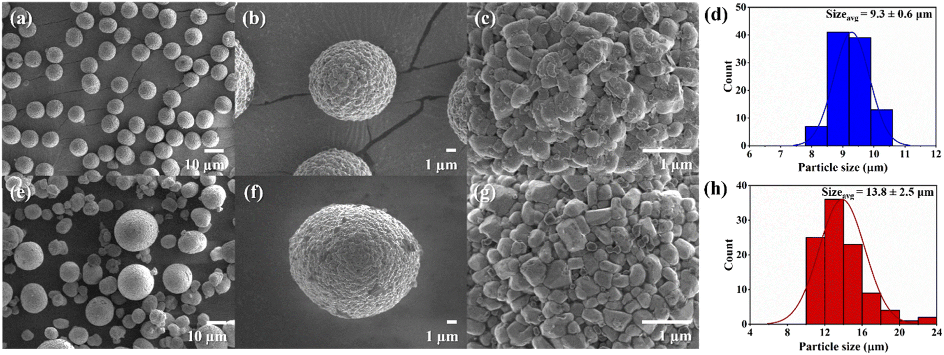 | ||
| Fig. 1 Top-view FESEM images with different magnifications of the (a)–(c) NMC90 powder and (e)–(g) the NMC80 powder and the particle size distribution of the (d) NMC90 and (h) NMC80 powders. | ||
The elemental composition of the NMC90 and NMC80 powders was analyzed using FESEM-EDX (Fig. S2 and S3†). The detailed elemental compositions from FESEM-EDX are given in Table S1,† where the NMC80 powder includes 80.3% Ni, 9.0% Mn, and 10.7% Co, while the NMC90 powder consists of 90.1% Ni, 4.7% Mn, and 5.2% Co. The structures of both samples was determined through XRD and Rietveld refinement (see Fig. S4 and Table S1†). The XRD patterns of NMC80 and NMC90 (Fig. S4a and b†) represent the R![[3 with combining macron]](https://www.rsc.org/images/entities/char_0033_0304.gif) m space group with hexagonal crystallographic patterns. The refinement results in Table S2† reveal cation mixing for NMC90 and NMC80 with percentages of 1.24 and 1.78%, respectively, which are acceptable because they are <5%. The BET surface area, pore volume, and pore size of the NMC80 and NMC90 electrodes are also listed in Table S3.†
m space group with hexagonal crystallographic patterns. The refinement results in Table S2† reveal cation mixing for NMC90 and NMC80 with percentages of 1.24 and 1.78%, respectively, which are acceptable because they are <5%. The BET surface area, pore volume, and pore size of the NMC80 and NMC90 electrodes are also listed in Table S3.†
The automatic roll-to-roll coating machine was employed for negative and positive electrode production in 18650 cylindrical configuration cells. Fig. 2 displays the top-view and cross-sectional FESEM images of the NMC90 and NMC80 electrodes, which showed well-packed NMC particles on the electrode with carbon black and PVDF. Notably, the NMC90 particles exhibited a more well-ordered arrangement and uniform particle size than NMC80. The pore volume and surface area of both electrodes were analyzed using BET surface area analysis (Table S3†). The NMC80 electrode had a larger pore volume than the NMC90 electrode (0.0032 and 0.0026 cm3 g−1, respectively) and a higher surface area (1.0883 and 1.0347 m2 g−1, respectively), indicating that the non-uniform particle size resulted in more void space between the particles in the electrode.
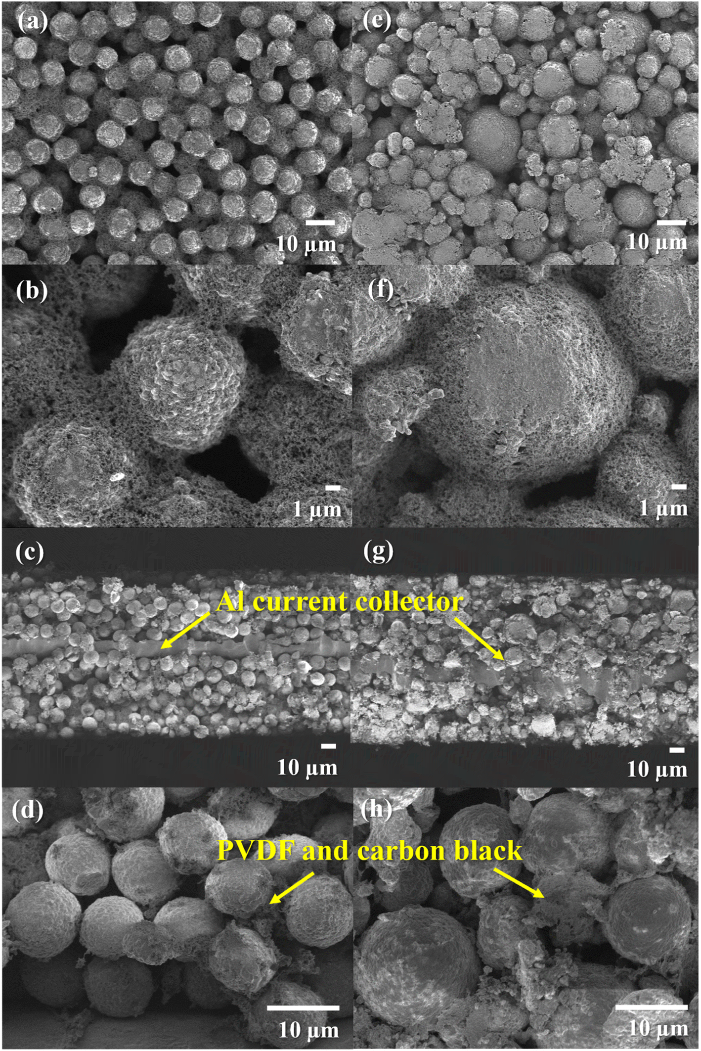 | ||
| Fig. 2 Top-view FESEM images of the NMC90 electrode at (a) low magnification, (b) high magnification and the NMC80 electrode at (e) low magnification and (f) high magnification, as well as cross-sectional FESEM images of the NMC90 electrode at (c) low magnification, (d) high magnification and the NMC80 electrode at (g) low magnification and (h) high magnification. | ||
3.2 Electrochemical properties
To assess the practical capacity of the cells, the electrochemical properties were first determined in a half-cell coin cell configuration (CR2032). The potential profiles of the NMC80 and NMC90 electrodes were examined in the potential range 3.0–4.3 V vs. Li/Li+ at 0.1C and their specific discharge capacities were 185.3 and 213.8 mA h g−1, respectively (Fig. S5†). The GITTs measurement were then made to investigate the lithium diffusivity of the cathode materials and both samples exhibited a linear relationship between potential and τ1/2 (Fig. S6†).29 The lithium diffusivity of NMC80 and NMC90 during charging and discharging at 0.1C with an upper cutoff voltage at 4.3 V vs. Li/Li+ is presented in Fig. S7.† The particle size distribution did not affect lithium ion diffusion at slow current densities. The diffusivity of the materials is described further in the following sections on the rate capability test and the GITT results after the stability test.Full-cell tests were performed on both samples in the 18650-cylindrical configuration to demonstrate the practical applications. The electrochemical performances of both samples were conducted following a formation step and capacity determination protocol (see Experimental section). The cells underwent electrochemical testing, including rate capability and stability tests with a cutoff voltage between 3.0 and 4.2 V. The testing protocol for the rate capability test involved fixed CCCV charging at 0.5C and various CC discharging at 0.1, 0.25, 0.5, 0.75, 1.0, 2.0, 3.0, 4.0, and 5.0C, followed by turning back to 0.1C.
The specific discharge capacity of both samples was measured and is plotted in Fig. 3a. The NMC90/graphite cell presented larger discharge capacity at all C-rates, especially at high C-rates, such as 4.0 and 5.0C, higher than 1.5 and 50 times the NMC80 cell, respectively. The discharge profiles of NMC90 and NMC80 cells at each C-rate are shown in Fig. S8a and b.† The discharge capacity based on the cell for both samples is presented in Fig. S8c.† The NMC90 cell provided a lower potential drop than the NMC80 cell at the same current density, especially at 5.0C, suggesting that the uniform particles mitigated the internal resistance (IR) of the cell (Fig. 3b and Table S4†). The rate capability results imply that the uniform particle size of the NMC90 cell can provide a better Li+ diffusion pathway, leading to outstanding discharge capacity even at a high C-rate and reducing the IR drop in the battery.25,30–32
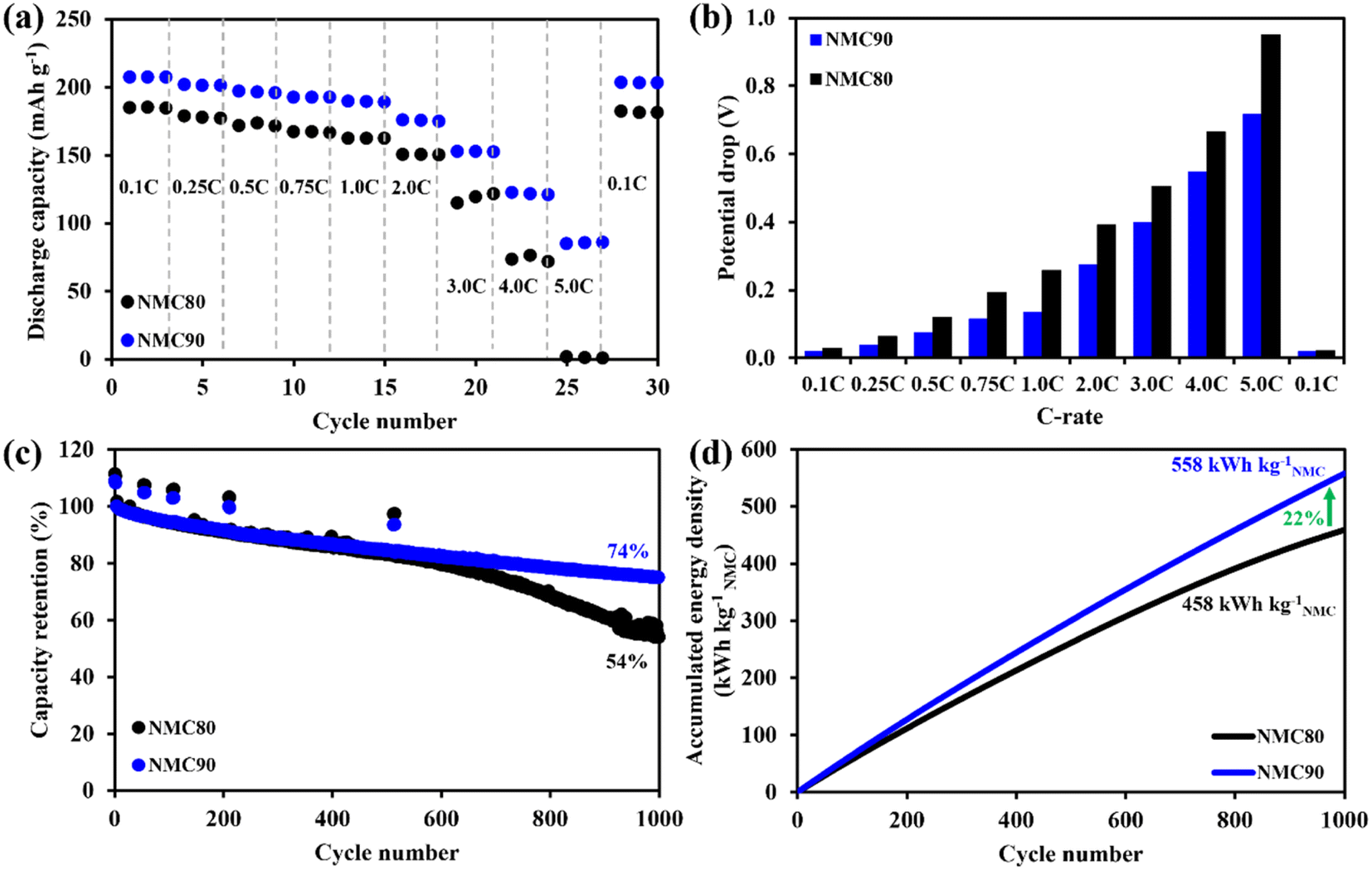 | ||
| Fig. 3 Electrochemical performance in cylindrical configuration. (a) Discharge capacity based on the active cathode material at various current densities from 0.1 to 5.0C. (b) Potential drop from rate capability of NMC90 and NMC80 cells. (c) Capacity retention for stability performance. (d) Accumulated energy density based on the active material level for long-term cycling performance. | ||
To evaluate the stability of the battery, an asymmetrical protocol was used, which involved CCCV charging at 0.5C and CC discharging at 1.0C within a potential window of 3.0–4.2 V. The long-term cycling performance was assessed by including a check-up protocol with CCCV charging and CC discharging at 0.1C. Fig. 3c shows that the NMC80 and NMC90 cells exhibited capacity retentions of 53.9 and 73.6%, respectively, after 1000 cycles at 1.0C. At the cell level, NMC90 and NMC80 had discharge capacities of 1448 and 1054 mA h, respectively, after 1000 cycles (Fig. S9a†). At the active material level, NMC90 and NMC80 demonstrated specific capacities of 138.5 and 90.4 mA h g−1 after 1000 cycles (Fig. S9b†). The voltage profiles at the 1st, 500th and 1000th cycles of the NMC90 and NMC80 cells are presented in Fig. S9c and d.† The voltage differences between charge and discharge during cycling are displayed in Fig. S9e.† After 1000 cycles, delta V in the case of the NMC90 cell was 0.58 V, whereas delta V of the NMC80 cell was 0.76 V. The NMC90 cell showed a better stability with lower polarization than the NMC80 cell, suggesting that the uniform particles enhance cell stability with lower kinetic hindrance, even with the high Ni content in the layered oxide material. Furthermore, the NMC90 cell delivers an accumulation energy density of 558 kW h kgNMC−1, 22% higher than the NMC80 cell (Fig. 3d). The accumulated energy density based on the cell level for both samples is shown in Fig. S9f.†
In addition, the potential profiles of both samples during cycling were examined in the check-up steps (Fig. S10†). The NMC90/graphite cell showed a capacity drop from 2090 to 1837 mA h (203 to 179 mA h g−1) from the 3rd to the 515th cycle, whereas the NMC80/graphite cell decreased from 2175 to 1902 mA h (185 to 162 mA h g−1). The voltage differences between the charge and discharge curves at the check-up steps in Fig. S10c and d† indicate that the NMC80 cell had slightly higher polarization than the NMC90 cell.
To better understand this effect, the dQ/dV plots at 0.1C were examined (Fig. 4). Both samples displayed identical phase transformation curves for the NMC materials. Notably, at the C6 to LiCx peak, which corresponds to kinetic hindrance in the cell (Fig. 4c and d), the peak of the NMC90 cell shifted to the right-hand side by 0.0338 V, which is less than the shift observed in the NMC80 cell (0.0517 V). This finding suggests that the uniform particle size of NMC90 can provide better Li+ diffusion with a lower kinetic limitation. The results therefore suggest that the particle size distribution of the Ni-rich layered oxide cathode materials is a crucial part of the electrochemical performance, with the narrow distribution of the NMC90 cell demonstrating a higher energy density and better retention.
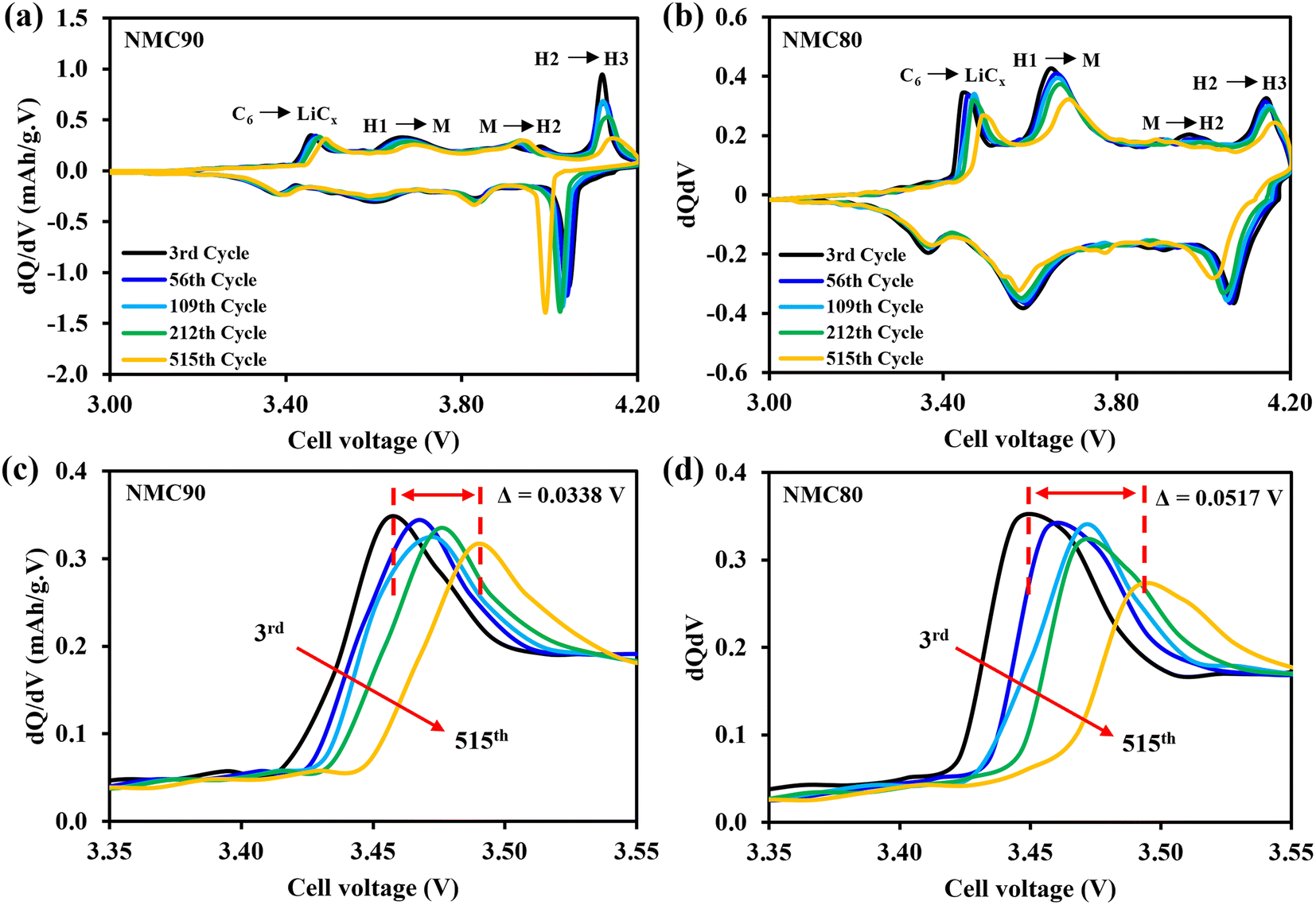 | ||
| Fig. 4 dQ/dV plots at 0.1C within the voltage range 3.0–4.2 V for the 3rd, 56th, 109th, 212th, and 515th cycles of the (a) NMC90 and (b) NMC80 cells. dQ/dV plots in the C6 to LiCx region of the (c) NMC90 and (d) NMC80 cells. | ||
All the cells were disassembled after 1000 cycles to examine the lithium diffusivity via the GITT technique. Fig. 5a and b shows dQ/dV plots of the NMC80 and NMC90 cells, respectively, with the three phase transition regions (H1–M, M–H2, and H2–H3). The chemical diffusion coefficient of both samples before and after cycling is presented in Fig. 5c. Both samples displayed a lower lithium diffusivity than the cells before cycling, especially the NMC80 cell, which was less than one order of magnitude. Note that the GITT measurement has diverse parameters and assumptions based on dense planar electrodes.
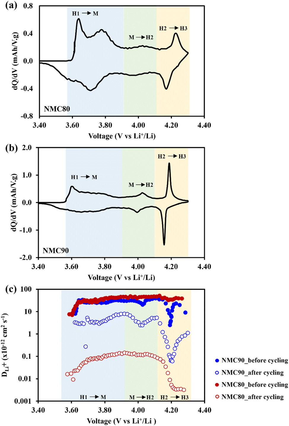 | ||
| Fig. 5 dQ/dV plots at 0.1C within the voltage range 3.0–4.3 V in half-cell coin cell of (a) NMC80 and (b) NMC90 and (c) the lithium diffusivity from the GITT measurement of the NMC90 and NMC80 cells before and after 1000 cycles at 0.1C. | ||
The Atlung method is an optional measurement for calculating lithium diffusivity (see Experimental section).33 The cumulative capacities from 5C to C/160 of the NMC80 and NMC90 cells before and after cycling are shown in Fig. S11.† The primary particle radius distribution of the NMC90 and NMC80 cells is shown in Fig. 6a and b, respectively. Both samples exhibited an analogous average radius of 0.25 ± 0.03 μm. The DLi+ values obtained from an average particle radius are shown in Fig. 6c. Before cycling, the DLi+ values of the NMC80 and NMC90 cells were almost the same (DLi+,avg,NMC90 = 9.96 × 10⁻¹⁴ cm2 s−1 and DLi+,avg,NMC80 = 9.86 × 10⁻¹⁴ cm2 s−1). After 1000 cycles, the lithium diffusion coefficient of the NMC90 cell outperformed that of the NMC80 cell with a higher order of magnitude (DLi+,avg,NMC90 = 1.49 × 10⁻¹⁴ cm2 s−1 and DLi+,avg,NMC80 = 6.98 × 10⁻¹⁵ cm2 s−1). Interestingly, the lithium diffusivity from the GITT and Atlung techniques exhibited the same trend, suggesting that DLi+ from the GITT method is still reliable even with the several assumptions of this technique. From the results, the narrow particle size distribution effectively improves lithium ion transport after long-term cycling.
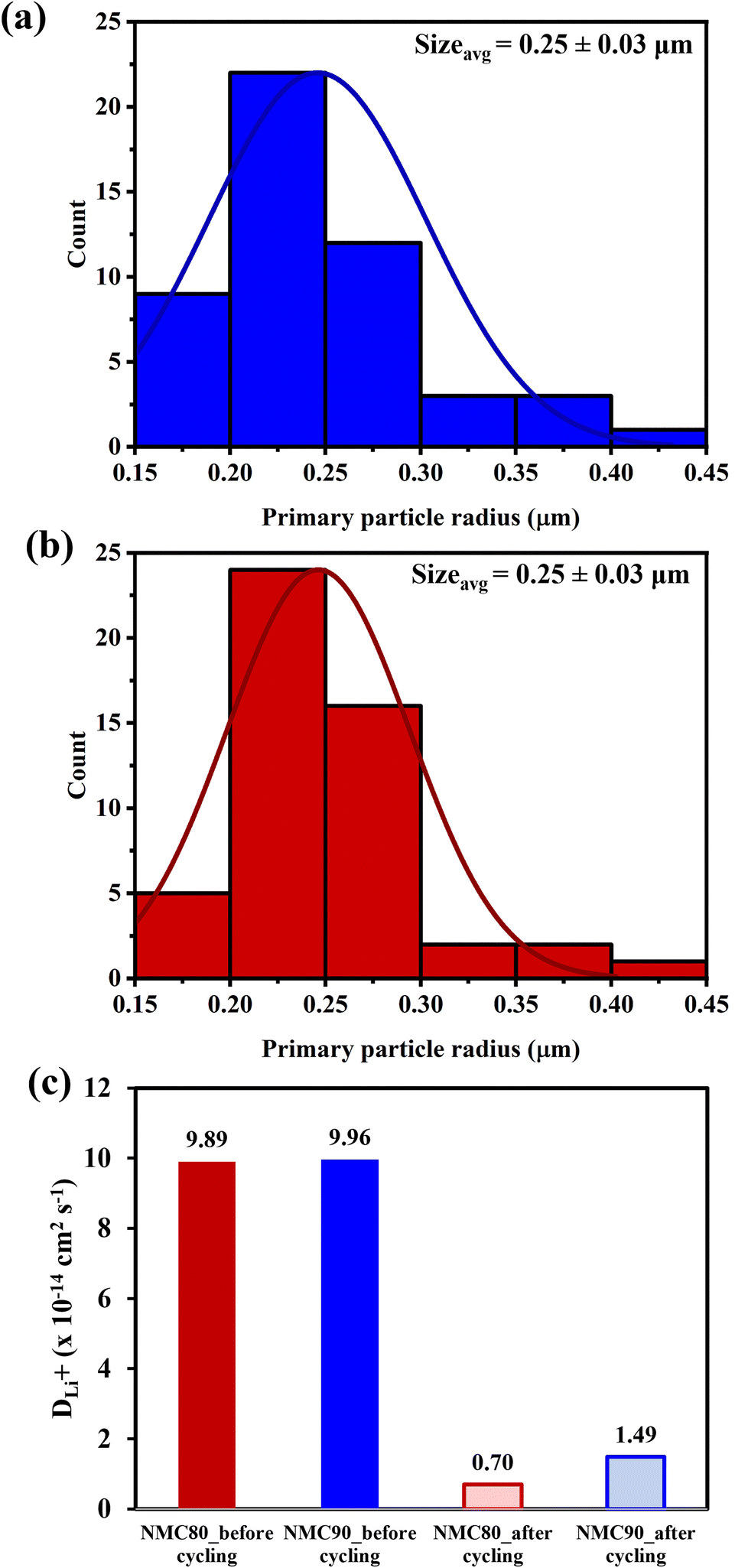 | ||
| Fig. 6 Primary particle size distribution of the (a) NMC90 and (b) NMC80 powders and (c) the Li+ diffusion coefficient from the Atlung method for the NMC90 and NMC80 cells before cycling and after cycling. | ||
The formation of secondary particle cracking on cycling leads to a poor battery life span. Capacitance measurements were used to investigate microcracking during cycling using in situ EIS without post-mortem of the cell (see Experimental section).34,35 The cells were cycled for 10 cycles to collect impedance data from each cycle. Fig. S12a† presents an example of the Nyquist plot with an equivalent circuit with a fitting curve for capacitance measurement. The specific capacitance of the NMC80 and NMC90 cells is shown in Fig. S12b.† At the conditioning step, the capacitance of the NMC80 and NMC90 cells was 0.120 and 0.110 F g−1, respectively. After 10 cycles, the NMC90 cell had a capacitance of 0.144 F g−1. By contrast, the NMC80 cell had a 43% higher capacitance (0.254 F g−1), indicating that the NMC80 cell has a larger surface area of particle cracking, leading to the penetration of more electrolyte into the active material and, as a consequence, further parasitic reaction.
3.3 In operando XRD
The change of cathode structure at the crystal lattice level through the full-cell pouch cells was studied through in operando XRD measurements. After the formation step, the cells were operated at 10 mA with the upper cutoff voltage of 4.3 V for two cycles. Rietveld refinement was applied to calculate the lattice parameters during charging and discharging. Fig. S13† shows the structural change from the refinement results, including the a-axis and c-axis lattice parameters and the unit cell volume for the NMC90 and NMC80 cells.The initial a-axis and c-axis lattice parameters of the NMC80 cell are 2.859(3) and 14.208(7) Å, whereas those of the NMC90 cell are 2.857(3) and 14.197(0) Å, respectively. During the first charging cycle, the changes in the a-axis value of the NMC80 and NMC90 cells are 0.80 and 0.79%, respectively. The unit cell volume changes by 2.64 and 4.45% for the NMC80 and NMC90 cells, respectively, which also relate to the c lattice parameter. For the lattice parameter along the a-axis, both samples display a reduction and expansion in the a-value during the discharge and charge processes. The change in unit cell volume is identical in aspect to that of the a-lattice. For the c-axis lattice parameter, both samples exhibit increasing c-values during the initial charging process because the oxidized transition metals enlarge the interslab repulsion during lithium extraction from the cathode material.
Toward the end of the charging process, a considerable amount of lithium ions exit the lithium layer, leading to a sudden reduction in the c-value, which reduces the electrostatic repulsion between the transition metal layers.36 During discharging, the c-axis lattice parameter immediately enlarges and then sluggishly lowers through lithiation at the cathode side. The changes in the c lattice value of the NMC80 and NMC90 cells at the first charging process are 1.73 and 3.48%, respectively. The greater change in the c-axis parameter indicates a larger amount of lithium extraction from the lithium slab, leading to a higher capacity in the NMC90 cell.20 Previous studies have consistently found that excessive shrinkage in the c-direction negatively affects the structural integrity and leads to a significant deterioration in capacity.10,11,36,37 However, the NMC90 cell exhibits a greater change in the c lattice value, but outstanding electrochemical performance. These findings indicate that the anisotropic volume change does not solely dictate the electrochemical performance. Additional factors, including the particle size distribution and surface treatment, have crucial roles in maintaining capacity retention.
3.4 In situ gas analysis
Ni-rich layered oxide cathode materials typically confront severe parasitic reactions from the electrolyte under high-voltage conditions during the charging process, directly affecting gas evolution in the cell and limiting lithium diffusion at the active material surface.38In situ DEM measurements were used to investigate the gas evolution of the jelly-roll cells during the formation step at high voltage for the first cycle. The potential profile for the first two cycles of the NMC90 and NMC80 cells are shown in Fig. S14a and S15a,† respectively, in combination with the cumulative gas evolution in Fig. S14b and S15b.† Both samples exhibit a similar trend of generated gases during cycling. At the beginning of the first charge, the H2 signal rapidly increases due to the reduction of FEC to form the SEI layer on the graphite electrode.39 For the second cycle with a high voltage up to 4.5 V, gas species, including H2, CO2, and CO, are found during this cycle, significantly increasing at voltages higher than 4.3 V, which is attributed to the decomposition of EC, DEC, and FEC.40 Notably, the generation of CO2 is a favorable occurrence resulting from the ring-opening of EC on the surface of the NMC cathode.41 Additionally, CO is produced through the reduction of the DEC and EC electrolytes.42During the second cycle at 4.5 V, the NMC80 cell detects a CO2 signal 1.75 times higher than the NMC90 cell. This observation suggests that the higher void space in the electrode with non-uniform particles influences electrolyte penetration into the cathode electrode. This leads to more pronounced side-reactions and a significant increase in gas evolution within the system. Furthermore, the reduction of protic oxidation species in the electrolyte is crucial for the formation of H2. The reduced form of residual H2O in the electrolyte at the graphite electrode also impacts H2 generation in the cell.41 The DEMS results reveal that the NMC80 cell generates higher amounts of gases, suggesting more parasitic reactions than the NMC90 cell. This agrees with the capacitance result that the NMC80 cell has a more elevated active material surface area on cycling. The results obtained from DEMS demonstrate that a narrow particle size distribution and surface coating positively influence gas evolution during cycling and further prevent parasitic reactions, even at high voltages.
3.5 Safety test according to the United Nations 38.3 standard
Maintaining transportation safety is crucial for LIBs, particularly in practical applications. We applied the UN38.3 standard to address safety concerns (see Experimental details).43 Both the NMC90 and NMC80 cells successfully passed the safety evaluation for altitude, thermal, shock, and short circuit tests with a 100% pass rate without cell leakage, breakage, or fire (Table S5†). Neither sample experienced bursting in the impact test, resulting in a 100% pass rate. The heat curves of both cells during impact testing indicated a maximum temperature < 110 °C, suggesting the absence of active material decomposition (Fig. S16†). The video for the thermal, shock, and impact tests is included in the ESI.† These results imply that the battery configuration employed in this study meets safety standards and has the potential for further development and scalability in practical applications.4 Conclusions
Our study has shown that the particle size distribution is a critical factor affecting the electrochemical performance of Ni-rich layered oxide cathode materials. The NMC90 cell, with its uniform secondary particle sizes, exhibits superior rate capability, stability, and energy density compared with the NMC80 cell. These findings are supported by in operando XRD and Atlung lithium diffusion coefficient measurements. The superior electrochemical performance of the NMC90 cell can be attributed to its improved lithium ion diffusivity. The uniform particle sizes of the NMC90 cell provide a more continuous pathway for lithium ions to travel, resulting in faster charging and discharging rates. Additionally, the battery configuration employed in this study meets safely standards. The findings of our study have important implications for the design of next-generation Ni-rich layered oxide cathode materials. By controlling the particle size distribution, it is possible to achieve high-performance cathode materials with improved rate capability, stability, and energy density. This could lead to the development of more efficient and reliable LIBs for a variety of applications.Data availability
The data that support the findings of this study are available in the ESI of this article.†Author contributions
Nichakarn Anansuksawat: characterizations, fabrication of 18650 lithium ion battery cells, investigation, formal analysis, writing – review & editing. Thitiphum Sangsanit: fabrication of 18650 lithium ion battery cells, investigation, formal analysis, writing – review & editing. Surat Prempluem: fabrication of 18650 lithium ion battery cells, investigation, formal analysis, writing – review & editing. Kan Homlamai: fabrication of 18650 lithium ion battery cells, investigation, formal analysis, writing – review & editing. Worapol Tejangkura: fabrication of 18650 lithium ion battery cells, investigation, formal analysis, writing – review & editing. Montree Sawangphruk: funding acquisition, supervision, investigation, resources, writing – review & editing, conceptualization, formal analysis.Conflicts of interest
The authors declare that they have no known competing financial interests or personal relationships that could have appeared to influence the work reported in this paper.Acknowledgements
This work was financially supported under Program Management Unit for National Competitiveness Enhancement (PMU-C) by Office of National Higher Education Science Research and Innovation Policy Council (NXPO) and IRPC Company Limited, Thailand Science Research and Innovation (TSRI) under the Fundamental Fund by TSRI (2023–2024) and Vidyasirimedhi Institute of Science and Technology (VISTEC) as well as Energy Policy and Planning Office (EPPO), Ministry of Energy, Thailand. In addition, the Frontier Research Centre (FRC) supported this work, VISTEC.References
- J. W. Choi and D. Aurbach, Promise and reality of post-lithium-ion batteries with high energy densities, Nat. Rev. Mater., 2016, 1(4) DOI:10.1038/natrevmats.2016.13.
- R. Schmuch, R. Wagner, G. Hörpel, T. Placke and M. Winter, Performance and cost of materials for lithium-based rechargeable automotive batteries, Nat. Energy, 2018, 3, 267–278, DOI:10.1038/s41560-018-0107-2.
- M. Chen, et al., Recycling End-of-Life Electric Vehicle Lithium-Ion Batteries, Joule, 2019, 3, 2622–2646, DOI:10.1016/j.joule.2019.09.014.
- M. Li and J. Lu, Cobalt in lithium-ion batteries, Science, 2020, 367, 979–980, DOI:10.1126/science.aba9168.
- Y. Mao, et al., High-Voltage Charging-Induced Strain, Heterogeneity, and Micro-Cracks in Secondary Particles of a Nickel-Rich Layered Cathode Material, Adv. Funct. Mater., 2019, 29, 1900247, DOI:10.1002/adfm.201900247.
- N. Anansuksawat, et al., Reducing intrinsic drawbacks of Ni-rich layered oxide with a multifunctional materials dry-coating strategy, J. Power Sources, 2023, 554, 232324, DOI:10.1016/j.jpowsour.2022.232324.
- P. Bunyanidhi, et al., Mechanofusing garnet solid electrolyte on the surface of Ni-rich layered oxide cathode towards high-rate capability of cylindrical Li-ion battery cells, J. Power Sources, 2022, 549, 232043, DOI:10.1016/j.jpowsour.2022.232043.
- P. Chiochan, et al., Reducing Intrinsic Drawbacks of Ni-rich Layered Oxide Cathode Materials with a Dry Coating Concept of Quasi-solid Nanomaterials towards High-performance Cylindrical Li-ion Batteries, J. Electrochem. Soc., 2022, 169, 110532, DOI:10.1149/1945-7111/aca2e2.
- K. Srimanon, S. Vadivel and M. Sawangphruk, Inhibition of Gas-evolved electrolyte decomposition in cylindrical Li-ion battery cells of Ni-rich layered oxide with a dry coating process without post thermal annealing, J. Power Sources, 2022, 550, 232150, DOI:10.1016/j.jpowsour.2022.232150.
- H.-H. Ryu, K.-J. Park, C. S. Yoon and Y.-K. Sun, Capacity Fading of Ni-Rich Li[NixCoyMn1–x–y]O2 (0.6 ≤ x ≤ 0.95) Cathodes for High-Energy-Density Lithium-Ion Batteries: Bulk or Surface Degradation?, Chem. Mater., 2018, 30, 1155–1163, DOI:10.1021/acs.chemmater.7b05269.
- G. W. Nam, et al., Capacity Fading of Ni-Rich NCA Cathodes: Effect of Microcracking Extent, ACS Energy Lett., 2019, 4, 2995–3001, DOI:10.1021/acsenergylett.9b02302.
- T. Weigel, et al., Structural and Electrochemical Aspects of LiNi0.8Co0.1Mn0.1O2 Cathode Materials Doped by Various Cations, ACS Energy Lett., 2019, 4, 508–516, DOI:10.1021/acsenergylett.8b02302.
- W. Lee, et al., Advances in the Cathode Materials for Lithium Rechargeable Batteries, Angew Chem. Int. Ed. Engl., 2020, 59, 2578–2605, DOI:10.1002/anie.201902359.
- Z. Cui, Q. Xie and A. Manthiram, Zinc-Doped High-Nickel, Low-Cobalt Layered Oxide Cathodes for High-Energy-Density Lithium-Ion Batteries, ACS Appl. Mater. Interfaces, 2021, 13, 15324–15332, DOI:10.1021/acsami.1c01824.
- K.-J. Park, et al., Improved Cycling Stability of Li[Ni0.90Co0.05Mn0.05]O2 Through Microstructure Modification by Boron Doping for Li-Ion Batteries, Adv. Energy Mater., 2018, 8, 1801202, DOI:10.1002/aenm.201801202.
- H. H. Sun, et al., Transition metal-doped Ni-rich layered cathode materials for durable Li-ion batteries, Nat. Commun., 2021, 12, 6552, DOI:10.1038/s41467-021-26815-6.
- F. A. Susai, et al., Stabilized Behavior of LiNi0.85Co0.10Mn0.05O2 Cathode Materials Induced by Their Treatment with SO2, ACS Appl. Energy Mater., 2020, 3, 3609–3618, DOI:10.1021/acsaem.0c00098.
- C. Geng, et al., A Low-Cost Instrument for Dry Particle Fusion Coating of Advanced Electrode Material Particles at the Laboratory Scale, J. Electrochem. Soc., 2020, 167, 110509, DOI:10.1149/1945-7111/aba00e.
- L. Sharma, M. Yi, E. Jo, H. Celio and A. Manthiram, Surface Stabilization with Fluorine of Layered Ultrahigh-Nickel Oxide Cathodes for Lithium-Ion Batteries, Chem. Mater., 2022, 34, 4514–4522, DOI:10.1021/acs.chemmater.2c00301.
- N. Phattharasupakun, et al., Core-shell Ni-rich NMC-Nanocarbon cathode from scalable solvent-free mechanofusion for high-performance 18650 Li-ion batteries, Energy Storage Mater., 2021, 36, 485–495, DOI:10.1016/j.ensm.2021.01.032.
- S. Tubtimkuna, N. Phattharasupakun, P. Bunyanidhi and M. Sawangphruk, Diffusion of Zirconium (IV) Ions from Coated Thick Zirconium Oxide Shell to the Bulk Structure of Ni-Rich NMC811 Cathode Leading to High-Performance 18650 Cylindrical Li-Ion Batteries, Adv. Mater. Technol., 2022, 7, 2200436, DOI:10.1002/admt.202200436.
- S. Vadivel, K. Srimanon and M. Sawangphruk, Regulating the cationic rearrangement of Ni-rich layered oxide cathode for high-performance Li-ion batteries, J. Power Sources, 2022, 537, 231526, DOI:10.1016/j.jpowsour.2022.231526.
- S. P. Sheu, C. Y. Yao, J. M. Chen and Y. C. Chiou, Influence of the LiCoO2 particle size on the performance of lithium-ion batteries, J. Power Sources, 1997, 68, 533–535, DOI:10.1016/S0378-7753(97)02623-2.
- H. Nara, et al., Impedance Analysis of LiNi1/3Mn1/3Co1/3O2 Cathodes with Different Secondary-particle Size Distribution in Lithium-ion Battery, Electrochim. Acta, 2017, 241, 323–330, DOI:10.1016/j.electacta.2017.04.153.
- S. T. Taleghani, B. Marcos, K. Zaghib and G. Lantagne, A Study on the Effect of Porosity and Particles Size Distribution on Li-Ion Battery Performance, J. Electrochem. Soc., 2017, 164, E3179–E3189, DOI:10.1149/2.0211711jes.
- M. Farkhondeh and C. Delacourt, Mathematical Modeling of Commercial LiFePO4 Electrodes Based on Variable Solid-State Diffusivity, J. Electrochem. Soc., 2011, 159, A177–A192, DOI:10.1149/2.073202jes.
- M. Safari and C. Delacourt, Mathematical Modeling of Lithium Iron Phosphate Electrode: Galvanostatic Charge/Discharge and Path Dependence, J. Electrochem. Soc., 2011, 158, A63, DOI:10.1149/1.3515902.
- A. Liu, et al., Factors that Affect Capacity in the Low Voltage Kinetic Hindrance Region of Ni-Rich Positive Electrode Materials and Diffusion Measurements from a Reinvented Approach, J. Electrochem. Soc., 2021, 168, 070503, DOI:10.1149/1945-7111/ac0d69.
- W. Weppner and R. A. Huggins, Determination of the Kinetic Parameters of Mixed-Conducting Electrodes and Application to the System Li3Sb, J. Electrochem. Soc., 1977, 124, 1569, DOI:10.1149/1.2133112.
- D.-W. Chung, P. R. Shearing, N. P. Brandon, S. J. Harris and R. E. García, Particle Size Polydispersity in Li-Ion Batteries, J. Electrochem. Soc., 2014, 161, A422–A430, DOI:10.1149/2.097403jes.
- F. Ulu Okudur, et al., LiNi0.5Mn1.5O4−δ (LNMO) as Co-free cathode for lithium ion batteries via solution-gel synthesis: particle size and morphology investigation, J. Alloys Compd., 2022, 892, 162175, DOI:10.1016/j.jallcom.2021.162175.
- Y. Ali, N. Iqbal and S. Lee, Simultaneous effect of particle size and location on stress development in the electrodes of lithium-ion batteries, Int. J. Energy Res., 2020, 44, 12145–12157, DOI:10.1002/er.5795.
- N. Phattharasupakun, et al., A Baseline Kinetic Study of Co-Free Layered Li1+x(Ni0.5Mn0.5)1−xO2 Positive Electrode Materials for Lithium-Ion Batteries, J. Electrochem. Soc., 2021, 168, 110502, DOI:10.1149/1945-7111/ac3157.
- S. Oswald, D. Pritzl, M. Wetjen and H. A. Gasteiger, Novel Method for Monitoring the Electrochemical Capacitance by In Situ Impedance Spectroscopy as Indicator for Particle Cracking of Nickel-Rich NCMs: Part I. Theory and Validation, J. Electrochem. Soc., 2020, 167, 100511, DOI:10.1149/1945-7111/ab9187.
- F. Riewald, et al., The LiNiO2 Cathode Active Material: A Comprehensive Study of Calcination Conditions and their Correlation with Physicochemical Properties Part II. Morphology, J. Electrochem. Soc., 2022, 169, 020529, DOI:10.1149/1945-7111/ac4bf3.
- A. O. Kondrakov, et al., Anisotropic Lattice Strain and Mechanical Degradation of High- and Low-Nickel NCM Cathode Materials for Li-Ion Batteries, J. Phys. Chem. C, 2017, 121, 3286–3294, DOI:10.1021/acs.jpcc.6b12885.
- H. Li, et al., An Unavoidable Challenge for Ni-Rich Positive Electrode Materials for Lithium-Ion Batteries, Chem. Mater., 2019, 31, 7574–7583, DOI:10.1021/acs.chemmater.9b02372.
- B. L. D. Rinkel, D. S. Hall, I. Temprano and C. P. Grey, Electrolyte Oxidation Pathways in Lithium-Ion Batteries, J. Am. Chem. Soc., 2020, 142, 15058–15074, DOI:10.1021/jacs.0c06363.
- A. L. Michan, et al., Fluoroethylene Carbonate and Vinylene Carbonate Reduction: Understanding Lithium-Ion Battery Electrolyte Additives and Solid Electrolyte Interphase Formation, Chem. Mater., 2016, 28, 8149–8159, DOI:10.1021/acs.chemmater.6b02282.
- R. Jung, M. Metzger, F. Maglia, C. Stinner and H. A. Gasteiger, Oxygen Release and Its Effect on the Cycling Stability of LiNixMnyCozO2(NMC) Cathode Materials for Li-Ion Batteries, J. Electrochem. Soc., 2017, 164, A1361–A1377, DOI:10.1149/2.0021707jes.
- M. Metzger, B. Strehle, S. Solchenbach and H. A. Gasteiger, Origin of H2 Evolution in LIBs: H2O Reduction vs. Electrolyte Oxidation, J. Electrochem. Soc., 2016, 163, A798–A809, DOI:10.1149/2.1151605jes.
- M. Onuki, et al., Identification of the Source of Evolved Gas in Li-Ion Batteries Using [sup 13]C-labeled Solvents, J. Electrochem. Soc., 2008, 155, A794, DOI:10.1149/1.2969947.
- Y. Chen, et al., A review of lithium-ion battery safety concerns: the issues, strategies, and testing standards, J. Energy Chem., 2021, 59, 83–99, DOI:10.1016/j.jechem.2020.10.017.
Footnote |
| † Electronic supplementary information (ESI) available. See DOI: https://doi.org/10.1039/d3sc05698h |
| This journal is © The Royal Society of Chemistry 2024 |