
 Open Access Article
 This Open Access Article is licensed under a
 Creative Commons Attribution 3.0 Unported Licence
Experimental study of CO2 capture from air via steam-assisted temperature-vacuum swing adsorption with a compact kg-scale pilot unit†
H. M.
Schellevis
 and
D. W. F.
Brilman
*
and
D. W. F.
Brilman
*
Faculty of Science and Technology, University of Twente, PO Box 217, 7500AE Enschede, The Netherlands. E-mail: d.w.f.brilman@utwente.nl
First published on 1st January 2024
Abstract
CO2 from air is one of the few sustainable carbon sources. Technologies to capture and concentrate this CO2 are being demonstrated on an increasingly large scale. Adsorption using supported-amine sorbent via a temperature-vacuum swing adsorption process is such technology. This work provides a detailed description of this technology and identifies options for process optimization based on experimental results. For this, a novel kg-scale pilot unit was designed and constructed with four parallel fixed bed reactors. Reproducible results were obtained during the complete experimental campaign of several weeks. The base case scenario led to a productivity of 1.3 kgCO2 per day or 0.27 kgCO2 kgs−1 per day with an energy consumption of 14.5 MJ kgCO2−1. The sensible heat of sorbent and inert material was the major contributor to the energy duty, while gas–solid contacting only accounted for a minor part. Various optimization options were identified based on the experimental results. Including these options, this potentially reduces the energy consumption of this direct air capture process to 5.1 MJ kgCO2−1.
Introduction
The most recent report of the Intergovernmental Panel on Climate Change concludes that we will reach a 1.5 °C temperature increase within two decades.1 CO2 emissions through fossil fuel burning is one of the main drivers of this global temperature increase. Only a drastic reduction of CO2 emissions could prevent dramatic environmental effects.1 Electrification of the energy sector can substitute fossil fuels, but a carbon source is still required for the production of a myriad of products.2 Sustainable carbon sources include biomass,3 chemical and mechanical recycling4 and CO2 from the atmosphere.5 All options have their own advantages and disadvantages. This study concerns the capture of CO2 from the atmosphere and is also referred to as ‘direct air capture’ (DAC). The main advantage of DAC is that this carbon source is location independent as air is available everywhere with a uniform composition. Moreover, it is able to mitigate emission from distributed sources when combined with permanent storage and can therefore play an important role in the transition towards an energy sector with net-zero CO2 emissions.The field of DAC is under rapid development. Demonstration of a few variations of the technology already occurs on large scale.6,7 These demonstrations employ two different CO2 separation technologies: absorption with alkaline solutions and adsorption with supported-amine sorbents. Keith et al. (Carbon Engineering) provide an extensive overview of their 1 MtCO2 per year absorption facility using an aqueous KOH solution as capture medium,8 whereas Climeworks utilizes adsorption with supported-amine sorbents in their envisioned 36 ktCO2 per year Mammoth facility in Iceland.9
The adsorption process can be performed with a variety of sorbents and gas–solid contacting methods.10–17 A number of techno-economic evaluations are appearing in literature, aiming to evaluate and compare these DAC technologies.5,18–20 Some evaluations are completely theoretical, whereas others are (partially) based on experimental results obtained at different scales. Not surprisingly, these estimations for cost of DAC and the energy requirements show a wide variation, even though the processes are very similar. Besides differences inherent to the variety in used sorbents, this is mainly due to the different assumptions made in these estimations. These assumptions are typically not thoroughly specified and important parameters are often missing. This makes it challenging to compare them. There is clearly a need for more (and more detailed-) experimental data.
This study provides a detailed description and analysis of an experimental study of a steam-assisted temperature-vacuum swing adsorption (S-TVSA) process for DAC. The objective is to identify the most promising options for process optimization based on experimental results. For this, a novel DAC pilot unit is developed with a design capacity of 1.0 kgCO2 d−1. The analysis incorporates an individual assessment of each step of the S-TVSA process. The performance is evaluated on basis of energy consumption and system productivity. This will allow other researchers to evaluate and benchmark their process on the different aspects.
To this aim, the manuscript is structured as follows. The first chapter (‘Process description’) provides a complete overview of the S-TVSA process, starting with the basic principles and followed by the design and overall performance of the constructed DAC pilot unit. Subsequently, each aspect of the process is evaluated separately in more detail. For this, the energy requirements are determined and opportunities for optimization are identified based on experimental data of the DAC pilot unit. The next chapter (‘Detailed experimental results’) shows typical experimental results for CO2 concentration, temperature and pressure during the different process steps and evidences the reproducibility of the results across the cycles. Then, several experimental studies are conducted to analyse the influence of operational parameters.
Process description
This chapter provides a description of the DAC pilot unit via an S-TVSA process. The pilot unit is designed and constructed at the University of Twente. System geometry and operational parameters can be found in ESI1.† The energy requirement of each process step is provided in this chapter. ESI2† gives the equations to calculate these energy requirements and proposes a convenient method to compare DAC processes based on several key parameters.Steam-assisted temperature-vacuum swing adsorption
Capturing CO2 from atmospheric air via an S-TVSA process consists of five steps: (1) adsorption, (2) evacuation, (3) heating, (4) desorption and (5) cooling (Fig. 1). In the first step, CO2 binds to the surface of the sorbent via a chemical reaction with amine groups that are present on the internal surface of the adsorbent. At a certain point, the adsorbent is saturated and adsorption is stopped. Subsequently, the combination of steps (2) to (5), here referred to as ‘regeneration’, prepares the adsorbent for the next adsorption step. At the same time, CO2 is released from the sorbent in concentrated form. | ||
| Fig. 1 Process steps in the steam-assisted temperature-vacuum swing adsorption process. The orange arrows indicate the cycle of the sorbent material. The black arrows indicate gas flows. | ||
In the adsorption step (1), atmospheric air is contacted with a DAC sorbent that is able to adsorb CO2 reversibly. The treated air stream with a reduced CO2 concentration is released back into the atmosphere. There is no constraint in the fraction of CO2 that must be captured from the ingoing air, as the goal is to capture CO2 in the most economically viable way and not to remove as much CO2 as possible from the ingoing air. The amount of CO2 captured depends on the operational parameters (e.g. superficial gas velocity and adsorption time) and on the properties of the sorbent. In our process, we use a commercially available sorbent (Lewatit® VP OC 1065) proven to be suitable for application under DAC conditions.13,17 This sorbent consists of a polymeric polystyrene–divinylbenzene support structure with primary benzylamine functionalization. Sorbent properties, such as the CO2 and H2O adsorption isotherm, reaction kinetics and chemical stability, are available in literature.12,21–24 The adsorption step is discussed in more detail in the section regarding ‘Gas–solid contacting’.
In the desorption step (4), the CO2-amine reaction is reversed and CO2 is collected as product gas. There are two methods driving the reverse reaction: elevating the temperature and reducing the CO2 partial pressure. When a product gas with a high CO2 concentration is desired, the regeneration must take place at high molar fraction of CO2 in the gas phase. At ambient system pressure, the partial pressure of CO2 is then high as well, much higher than in the feed during adsorption. Only increasing the temperature is then not sufficient to achieve adequate desorption. Hence, not only should the temperature be increased, the CO2 partial pressure must be reduced as well. This is achieved by operating at a reduced absolute system pressure. Additionally, a purge gas can be applied to reduce the partial pressure of CO2 even further by reducing the molar fraction in the gas. A condensable purge gas, such as steam, is then advantageous since it is easily separated from the product gas. All three actions (increase in temperature, reduction in system pressure and introduction of a steam purge) result in an energy penalty, which will be quantified in section named ‘Regeneration’.
Evacuation (2) and heating (3) are preparation steps for CO2 desorption. The evacuation step serves three purposes. Firstly, to reduce the absolute pressure to the desired desorption pressure. Secondly, to prevent residual air from the adsorption step to end up in the product gas, hence the evacuated gas will be purged to the atmosphere. Thirdly, to remove oxygen prior to heating and thereby avoid oxidative degradation of the amine groups. This oxidative degradation occurs noticeably above around 70 °C and accelerates rapidly with increasing temperature.24 It is therefore vital to remove oxygen before heating the sorbent. Once oxygen is removed, a heating step is required before the steam purge can be introduced. A temperature increase to well above the boiling point of water at the system pressure after evacuation is sufficient to avoid condensation of the steam purge. In the pilot unit, a minimum temperature of 50 °C is set as requirement before desorption (4) can start. This corresponds to a saturated water vapour pressure of 123 mbar. The desorption step is started by initiating the steam purge co-currently compared to the air flow. Eventually, the temperature during desorption will reach the temperature of the heating medium. However, desorption can be stopped at any point once sufficient desorption has occurred.
The cooling step (5) is present to reduce the temperature of the sorbent below the oxidative degradation threshold before pressurization with ambient air. Afterwards, a new adsorption step is initiated and further cooling to ambient temperature is facilitated by convective air flow.
The absolute minimum energy required for CO2 capture via adsorption is the reaction enthalpy of CO2. The reaction enthalpy for Lewatit® VP OC 1065 is here taken at a constant value of 75 kJ molCO2−1 or 1.70 MJ kgCO2−1.25 Other chemisorption sorbents have similar heats of reaction, e.g. amine-impregnated silica (80 to 100 kJ molCO2−1)26,27 and MOF (55 to 70 kJ molCO2−1).14,28 The selectivity of supported-amine sorbents towards CO2 is very high when compared to other components in air, except for H2O. Significant co-adsorption of H2O occurs at adsorption conditions, which are equal to the ambient conditions.29,30 Hourly weather data from Enschede, The Netherlands (ESI3†) between December 1st 2020 and December 1st 2021 show that the relative humidity is usually high, with an average value of 82%, mainly during the night and early morning hours. The temperature has a more normal distribution around the average value of 10 °C. This would result in a selectivity of 0.22 molCO2 molH2O−1 at equilibrium conditions and an additional energy penalty for H2O desorption of 4.4 MJ kgCO2−1. This already accounts for the beneficial effects of humidity on the CO2 equilibrium capacity at low CO2 partial pressure.29,31 However, it also assumes that sorbent regeneration is complete. For H2O this may be a reasonable assumption, but for CO2 a sorbent utilization of e.g. 60% is more likely. Assuming this, for illustration, the CO2 selectivity then drops to 0.13 molCO2 molH2O−1, resulting in an energy penalty of already 7.4 MJ kgCO2. This clearly demonstrates that H2O co-adsorption is an aspect to be reckoned with, since the energy penalty for H2O desorption can be a manifold of the energy penalty for CO2 desorption.
Fig. 2 presents a simplified flowsheet of the DAC process including all major elements, as well as a global mass balance and indication of temperature and pressure. The total process consists of four parallel fixed bed reactors of which three are always in adsorption mode and one is in regeneration mode (evacuation/heating/desorption/cooling). During the process, the sorbent remains fixed in the same compartment, thus the process conditions change sequentially inside a compartment. The process flow diagram can be divided roughly into four parts: (1) gas–solid contacting to facilitate adsorption, (2) a closed heating circuit to facilitate heating, (3) a closed cooling circuit to facilitate cooling and (4) a desorption section to produce CO2 at 5 bars.
 | ||
| Fig. 2 Simplified process flow diagram of the steam-assisted temperature-vacuum swing adsorption process with a global mass balance based on the experimental results using the design operational parameters. The process is divided into air–solid contacting (green), heating (red), cooling (blue) and desorption (black). Location of temperature, pressure, relative humidity and CO2 concentration measurements can be found in ESI1.† | ||
The reported values in Fig. 2 and in the remainder of this chapter correspond to the experimental results using the ‘design’ parameters (Table S1 in ESI1†), which will be introduced throughout this chapter. Note that this experiment was conducted inside the Process Hall of the UT High Pressure Laboratory in a relatively dry period. This resulted in an almost constant air inlet temperature of ∼20 °C and low relative humidity of only 20%. Furthermore, the (average) CO2 concentration (476 ppm) is somewhat elevated when compared to the outdoor atmosphere. At these conditions, this DAC process has a capacity of 1.3 kgCO2 d−1 corresponding to 0.27 kgCO2 kgs−1 d−1, with an energy consumption of 14.5 MJ kgCO2−1. The energy consumption is calculated from the detailed process parameters (flows, temperatures and pressures). With this, it is possible to determine the energy requirements of each individual process step and to identify the opportunities for process optimization in terms of operation and design.
Time-based process control regulates the duration of each process step (Fig. 3). The duration of evacuation (1 min), heating (10 min) and cooling (9 min) were determined by preparatory experiments and remain fixed over all cycles and experiments. Since continuous production of CO2 is desired, always one of the reactors is in regeneration mode, whereas the other three are in adsorption mode. To ensure that the reactor beds operate out of phase, the start of the adsorption step is delayed in reactors 2–4. This is indicated by the ‘initialization’ step in Fig. 3. With this additional constraint of having always one reactor in regeneration mode, it is only possible to set either the adsorption time or the desorption time. Here, we choose to set the desorption time at 30 min. A 30-second buffer between each regeneration step is required to collect water condensate from the water trap. This results in a total buffer of 2 min each cycle and an adsorption time of 152 min.
 | ||
| Fig. 3 The first 500 minutes of the time-based control scheme for each of the four reactors. | ||
Time-based control was chosen over signal-based control for ease of operation. In a signal-based process control, the process step durations are essentially controlled by ambient conditions and it is no longer ensured that one reactor is in regeneration mode at any time. In addition, a more serious issue can arise when a second reactor enters regeneration mode. In that case, cold air at ambient pressure inside this second reactor can flow via the shared outlet into the first reactor. This reactor is hot and at reduced pressure, leading to enhanced oxidative sorbent degradation. This risk on having more than one bed simultaneously in regeneration mode could not be mitigated in the current facility when using a signal-based control philosophy. Hence, we decided to use a control strategy with fixed time settings, which are equal for each bed.
Gas–solid contacting
Fig. 4 shows the detailed design of one part of the gas–solid contactor. It consists of two modular segments with a diameter of 40 cm that are stacked alternately: an air supply/removal segment and a reactor segment. The air supply/removal segment supplies ambient air to the reactor segment below and removes air from the reactor segment above. In addition, valves are placed inside to seal the reactor segments during regeneration. The reactor segment holds the sorbent material and is subject to the adsorption/regeneration cycles. Each reactor consists of 1.2 kg sorbent (dry weight) that is placed in between wire meshes of 0.4 mm with a bed thickness of 2.4 cm. Spacers ensure an even bed thickness over the reactor diameter and counteract the vacuum forces on the top and bottom of the reactor. Four layers of tubes (6 mm outer diameter) accommodate heat transfer during heating and cooling with a specific surface area of ∼150 m2 mr−3. Finally, steam can enter the reactor segment above the sorbent bed, while product gas is collected below the sorbent bed. These connections are closed during adsorption. | ||
| Fig. 4 Detailed design of one of the four parallel gas–solid contactors. The faded parts belong the reactors above or below. The dashed lines indicate the two modular segments: 1) air supply/removal and 2) reactor compartment. The air supply/removal segment holds the air inlet of the reactor below as well as the air outlet of the reactor above. | ||
Process parameters relating to the adsorption step at design conditions include a superficial gas velocity of 0.11 m s−1 and an adsorption time of 152 min. With this, a working capacity of 0.92 ± 0.02 molCO2 kgs−1 is achieved, equivalent to a CO2 production of 49 gCO2 per cycle for each reactor. The working capacity is a critical parameter for the energy requirements of the complete capture process. For example, the combination of this working capacity and the ambient conditions during the experiment lead to a selectivity of 0.88 molCO2 molH2O−1 with an energy penalty for H2O co-adsorption of only 1.12 MJ kgCO2−1. Note that the H2O working capacity was not measured experimentally. Instead, the equilibrium capacity was taken. Adsorption of H2O is much faster than adsorption of CO2 at these conditions,12 thereby anticipating complete adsorption and complete desorption of H2O. This is a conservative approach regarding H2O co-adsorption energy penalty.
Gas–solid contacting can account for a significant energy consumption due to the large amount of air that has to be treated. The average capture efficiency under design conditions is found to be 42%, meaning that 2760 m3 of air is required to capture 1 kg of CO2. Coupled with a pressure drop of 242 Pa between the air inlet and the air outlet, an energy consumption of 0.83 MJ kgCO2−1 is obtained, for a blower efficiency of 75%. The design of the segments (wire mesh, spaces, air supply configuration, heat transfer tubes) also contribute to the pressure drop, as well as the particle size distribution. In the hypothetical case that only the sorbent bed with uniform particles are responsible for the pressure drop, it reduces to 98 Pa following the Ergun equation. The minimum energy penalty for gas–solid contacting is then 0.34 MJ kgCO2−1.
Regeneration
Regeneration accounts for the majority of the energy input. This includes the previously mentioned 1.7 MJ kgCO2−1 that is required to desorb CO2 and 1.12 MJ kgCO2−1 to desorb H2O. Further energy requirements related to the S-TVSA cycle are found in the increase in temperature, reduction in pressure and addition of a steam purge. In addition, these actions introduce new operational (and optimization) parameters namely: temperature of the heating medium, desorption pressure, steam flowrate and temperature of the cooling medium.The ambient temperature influences heating and cooling (Fig. 5). For heating, it determines the starting temperature of the heating step and therefore the required temperature increase. For cooling, it determines the cooling rate, since the cold water circuit is cooled by an air cooler. The differences between the reactors in Fig. 5 are caused by the location of the thermocouples. Since the sorbent is a poor heat conductor, temperature gradients inside each of the beds are expected. The reported temperature is the average of six thermocouples, but already a slightly unequal distance to the heat transfer surface can make a notable difference. The spread in bed temperature after heating is larger than after cooling because the end temperature for cooling is closer to the temperature of the heat transfer medium. This results in a more uniform temperature distribution over the bed and the exact location of the thermocouples is of less importance. The time for cooling and heating is kept constant in the current experiments. However, the required time to reach the desired temperature for desorption depends on the ambient temperature. A similar argument holds for the temperature threshold below which the adsorption step can restart. Therefore, optimization of the duration of the heating and cooling step based on the ambient temperature is possible.
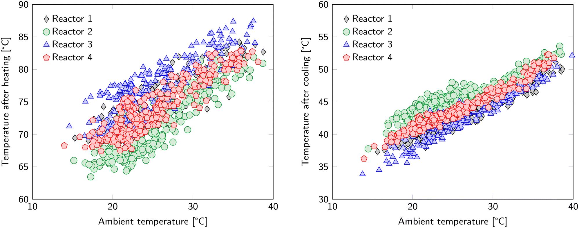 | ||
| Fig. 5 Average temperature of the reactors after the heating phase (left) and after the cooling phase (right). The hot water circuit has a temperature of 100 °C in these cycles. | ||
The sorbent is not the only material that is subject to the temperature swing. In fact, the whole reactor segment will experience the same temperature changes. This reactor segment has a mass of 3.95 kg. Having a specific heat capacity of 0.5 kJ kg−1 K−1, this leads to an additional energy penalty of 2.96 MJ kgCO2−1. Hence, reducing the ratio of the reactor heat capacity to sorbent bed heat capacity, which is 1.05 in the current configuration, can lead to significant energy savings. A system with circulating sorbents would eliminate this energy penalty completely. Therefore, this operational expense can be considered as the ‘price to pay’ when choosing a system with fixed sorbents with accompanying advantages compared to a system with circulating sorbents.
A third element that is subject to the temperature swing is the heat transfer medium that is present in the tubes inside the reactor segment. Each reactor contains only 0.25 kg of water in the heating/cooling tubes. However, as the specific heat capacity thereof is relatively high, this adds 1.57 MJ kgCO2−1 to the sensible heat requirements of the system. This is added to the energy penalty for the reactor segment to obtain the total sensible heat requirement of the reactor. Hence, the heat capacity ratio increases to 1.59.
The total sensible heat requirements for the temperature swing is 7.37 MJ kgCO2−1 for a CO2 working capacity of 0.92 molCO2 kgs−1. The sorbent accounts for 39%, the reactor material for 40% and the heat transfer medium for 21%.
To calculate the energy penalty, we assume that all water is condensed before the product compressor and that no CO2 dissolves in the condensed water. The former assumption is not completely true, since a water trap is also present before the vacuum pump. However, this is not actively cooled and most of the water will leave the system via the condenser. The latter assumption neglects the solubility of CO2 in water. In the current experiment, a maximum of 0.25% of the CO2 is lost here. However, when the CO2/H2O selectivity is lower, this CO2 loss can increase to around 1.5%. The total amount of product gas is calculated via the pressure increase in the product storage tank. Overall, the vacuum and compression work leads to an energy requirement of 1.81 MJ kgCO2−1 of which 20% is due to H2O co-adsorption, 30% is due to the steam purge and 50% is due to the product gas compression.
Water condensation occurs on two locations in the process. The first water trap is present before the vacuum pump and was installed to handle condensation of water in the tubing and therefore possible blockage of the gas stream and water slugging into the vacuum pump. No active cooling was installed in this trap and most of the water will eventually evaporate again. The second and main water trap is present after the vacuum pump, where a condenser at ∼2 °C cools down the product stream. At this position, the majority of the condensable water is collected. Preferably, most of the water is condensed in the first water trap. By installing active cooling in the first water trap (not implemented here!), the vacuum pump does not need to process this water vapour and this already could save up to 0.9 MJ kgCO2−1.
The CO2 purity of the product gas, as collected in the product tank in this study, is approximately 50 to 55%, with the remainder being air. The air originates from leaks into the product stream during the desorption process. It is anticipated that this was mainly due to experimental imperfections in sealing, which should be avoidable upon reworking the unit and at scaling up. In addition, not all air is evacuated at the end of evacuation. This accounts for approximately 2% of the current product gas stream. In the most optimal case of a product gas consisting only of CO2, at the same desorption pressure, the energy requirements for vacuum can be as low as 0.46 MJ kgCO2−1.
Overall energy requirement
Table 1 gives the overview of energy requirements for the S-TVSA process using supported-amine sorbents. The values in the first column are calculated from experimental results, neglecting thermal energy losses to the surroundings and sensible heat of the adsorbed phases. In contrast, no attempts for any heat integration are applied at this point. Overall, an energy duty of 14.5 MJ kgCO2−1 (4.03 kW h kgCO2−1) is required under the current operational conditions with a thermal energy requirement of 11.9 MJ kgCO2−1 (3.30 kW h kgCO2−1) and electrical energy requirement of 2.65 MJ kgCO2−1 (0.74 kW h kgCO2−1). Reducing energy consumption could be achieved by either the design of the process and contactor as well as by optimizing operational parameters. Identified, but not implemented, improvement options include:1. sorbent circulation: −4.53 MJ kgCO2−1;
2. pressure drop reduction of the reactor segments: −0.50 MJ kgCO2−1;
3. active cooling of first water trap: −0.90 MJ kgCO2−1; and
4. improved product purity: −0.45 MJ kgCO2−1.
Combining these options alone can already reduce the total energy required to 8.1 MJ kgCO2−1 (Table 1).

|
Gas–solid contacting is not necessarily a large energy contributor. Under the current operating conditions, it only accounts for 6% of the total energy duty (Table 1). Increasing the superficial gas velocity can therefore be beneficial. This will increase the pressure drop, but also increases the working capacity as the equilibrium capacity is not reached yet. That will then reduce the sensible heat requirements, which is the most energy consuming step in the process. In total, the sensible heat requirement accounts for more than 50% of the total energy consumption.
Circulation of sorbent from an adsorption compartment to a separate desorption compartment reduces the energy requirement up to 30%, but can lead to operational difficulties through solid handling. When opting for fixed sorbent, it is important to maximize the ratio of sorbent mass to reactor mass during the design of the gas–solid contactor. Scaling-up such gas–solid contactors to commercial scale likely reduces this heat capacity ratio already. One of the options is to increase the thickness of the bed, although it is difficult to visualize a priori the effect on the overall performance. Most likely, the gas velocity also needs to be increased to supply enough CO2 in the same period, but the capture efficiency is likely to increase as well. A longer adsorption time can also increase the working capacity and thereby reduce sensible heat requirements. However, this latter option will decrease the system productivity. In the current configuration, the criterion that one reactor is regenerating while three reactors are adsorbing is limiting the flexibility in adsorption time. However, for a new-to-build unit this is a degree of freedom. Overall, multiple optimization opportunities exist.
The temperature swing of the heat transfer medium, when applicable, is usually not considered. However, as shown in this work, it can already account for 10% of the total energy requirement. This heat moves directly from the hot water circuit to the cold water circuit upon cooling, where it is transported to the atmosphere via the air cooler. Instead, this heat can be redirected to the reactor that is about to start its regeneration phase. Then, the temperature in that reactor increases by some extent before starting the heating step and applying the heating medium to the coils. This strategy reduces the magnitude of the temperature swing somewhat, and with that the thermal energy requirement.
An alternative method to achieve the temperature swing is via microwave heating.32 This not only removes the use of a heat transfer medium, but also reduces the extent of the temperature swing of the reactor material. In addition, heat transfer limitations inside the poorly conducting sorbent bed are removed, which decreases the time required for heating and with this the productivity can be increased significantly. Thus, microwave heating is an interesting alternative to reduce energy requirements and increase productivity. However, it will lead to a more complex design of the gas–solid contactor.
The H2O co-adsorption energy penalty of 1.12 MJ kgCO2−1 is relatively low for this sorbent. Note that this is calculated based on the H2O equilibrium capacity at adsorption conditions during the experiment and not from experimental results. Values of 5 to 10 MJ kgCO2−1 are more realistic in the Northwest European climate, which can deem the economics of the process unacceptable. A dry climate could reduce this to 3 to 5 MJ kgCO2−1, which means that the geographic location is surely an important aspect in the viability of a DAC process.
Providing the thermal energy from surrounding air by means of a heat pump is an interesting option to reduce the absolute energy duty. The coefficient of performance (COP) depends on the temperatures of the heat sink and the heat source. In the current process, the heat source is ambient air at 20 °C and the hot sink is the hot water circuit at 110 °C. This is a relatively high temperature for the hot sink and a relatively large temperature difference. From a thermodynamic point of view, the maximum COP is then 4.3. In practise, the COP will be around 40% of the maximum COP.33 With this, the total energy demand for the optimized case reduces from 8.1 MJ kgCO2−1 to 5.1 MJ kgCO2−1 (1.4 kW h kgCO2−1). For the current pilot unit without other optimization options it reduces from 14.5 MJ kgCO2−1 to 9.6 MJ kgCO2−1.
The introduction of a purge gas increases the productivity, but also the energy requirements. Besides the before mentioned trade-off between CAPEX and OPEX, the size of the DAC system could play a role in the decision whether or not to apply a steam purge. When space is limited or if a compact DAC system is desirable, a steam purge will be beneficial. On the other hand, it adds complexity to the system.
A purge gas adds a constant energy penalty throughout the whole desorption step. Its benefits, however, might not be constant as desorption progresses. At the start of desorption, a high desorption rate can be present, even without a steam purge. At the end of desorption, especially for a long desorption time, the desorption rate can be too slow, even with a purge gas. Therefore, an optimized and variable purge gas flowrate over time may reduce the costs of purge gas generation, without affecting the productivity much.
Detailed experimental results
The previous chapter introduced the overall experimental results obtained for a kg-scale DAC system using an S-TVSA process. These experimental results were obtained with a set of ‘design’ operational parameters. This chapter provides a more elaborate view on how these results were obtained. First of all, the reproducibility of both the adsorption and desorption step is validated, both by comparing the performance of the individual sorbent beds as well as comparing the cycle-to-cycle performance. In this reproducibility check, especially the time-dependent profiles for the CO2 concentration, temperature and pressure are considered. Then, we evaluate the performance of the individual reactors via the productivity. Thereafter, we vary two operational parameters, namely the purge gas flowrate and cycle length. The purge gas flowrate was already shortly discussed and which will be elaborated in more detail. For the cycle length, we carried out three experimental runs of multiple days with a varying adsorption and desorption time.Reproducibility
Experiments with the kg-scale DAC unit ran continuously for several days, in which numerous adsorption–regeneration cycles took place following the scheme of Fig. 3. An important validation of the stability of the whole unit is whether all these cycles perform identical under identical circumstances. This reproducibility is assessed by comparing all cycles for each of the reactors. This sections only shows the result of a single reactor, the results of the other reactors can be found in ESI4.1.† As said, reproducibility can only be expected under identical operational conditions for each cycle. Ambient conditions are beyond our control. However, for the presented campaign these were rather stable for each cycle since we operated inside the laboratory (Fig. 6). Only the CO2 concentration shows minor fluctuations over time, but these are not expected to be directly visible in the results.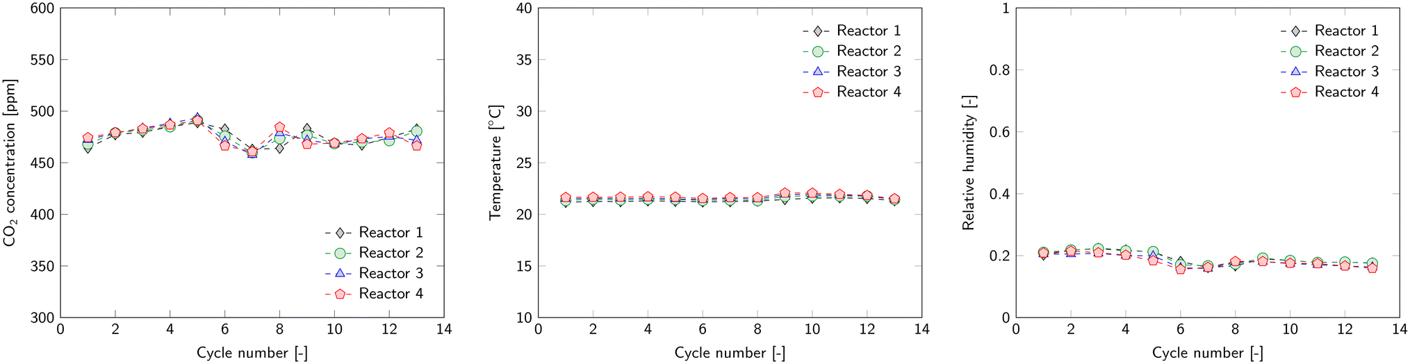 | ||
| Fig. 6 Average ambient CO2 concentration (left), temperature (middle) and relative humidity (right) during the adsorption phase of each cycle. | ||
Reproducibility of the adsorption step is assessed through the breakthrough curves. Fig. 7 shows all breakthrough curves of a single reactor (other reactors in ESI4.1†). The collection of lines in the top of the graph is the inlet concentration of each cycle and the bottom lines represent the outlet concentration. Overall, the breakthrough curves are very similar. Minor differences can be attributed to small variations in CO2 ingoing concentration. This also fluctuates a bit over time during a cycle depending on, for example, the occupancy of the laboratory. The sharp peaks in, predominantly the ingoing, CO2 concentration arise from the release of excess CO2 from the storage tank.
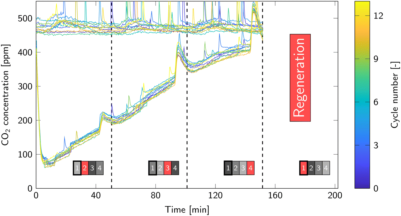 | ||
| Fig. 7 All breakthrough curves of reactor 1. The collection of graphs on the top are the ingoing concentration and the bottom graphs are the outgoing concentration. The dashed lines represent a switch in regeneration phase from one reactor to another; this is also indicated by the reactor scheme at the bottom. Here, a black/gray box represents the adsorption step and a red box represents a regeneration phase. The darker the box, the further along the adsorption phase. | ||
The dashed lines in Fig. 7 are moments when regeneration switches from one reactor to another. Just before this switch, a temporary increase in outgoing CO2 concentration occurs. This coincides with the cooling step of another reactor. Then, the cooling circuit heats up, because the air cooler is not able to dissipate this large amount of heat immediately. Consequently, the temperature of the other reactors increases by a few degrees (Fig. S6 in ESI4.1†). This decreases the CO2 equilibrium capacity of the sorbent and therefore the adsorption rate decreases. It is more severe near the end of the adsorption step, since the equilibrium capacity then becomes the limiting factor for the adsorption rate.
Regeneration relies on different utility systems compared to the adsorption step. Therefore, its reproducibility is assessed separately via the desorption temperature and pressure (Fig. 8). Both show reproducible results with nearly identical profiles over all 13 cycles. The temperature and pressure profiles of all reactors can be found in ESI4.1.†
 | ||
| Fig. 8 Temperature (left) and pressure (right) profiles during regeneration for all cycles of a single reactor. Note that the evacuation phase is not included in the figure. | ||
The temperature of the hot circuit is 110 °C, but the end temperature of the sorbent is 98 °C. During the heating step, the temperature flattens off for some time (in Fig. 8 at ca. 7 min). This is partly due to the energy requirement for desorption of H2O and CO2. However, predominantly it is due to a drop of the temperature of the hot water circuit. Cold water that is present in the tubes of the reactor enters the hot water circuit upon switching to the heating step. A single pass of this cold water through the water heater is not enough to heat it up completely to the desired 110 °C. At the end of the heating phase, the average temperature in the reactor is 81 °C. This is well above the boiling point of water at the reduced pressure. However, this is an average temperature and temperature gradients of 20 °C occur at this stage of the regeneration.
The pressure after evacuation is around 100 mbar, but decreases further in the heating step to around 50 mbar. Then, the increasing temperature as well as the release of CO2 and H2O cause the pressure to increase. A little drop in pressure is observed that corresponds to the temperature plateau. The addition of the steam purge and accompanying enhancement of desorption cause the pressure to increase a bit further until a maximum is reached around 80 mbar. When the desorption rates are dropping due to the reduced sorbent loading, so does the pressure until the end of the desorption step. At the beginning of the cooling step, an immediate drop in pressure occurs due to the removal of the steam purge. Further decrease in temperature causes the pressure to decrease as well until the end of cooling.
Productivity
The DAC pilot unit consists of four identical reactor beds. Therefore, the performance of each reactor bed should be very similar. However, it is impossible to manufacture four identical reactors. This shows for example in the vacuum pressure that is achieved during regeneration and the pressure drop during adsorption (Fig. 8 in ESI4.1†). Furthermore, the path that air travels before entering a reactor segments differs for each reactor. This results in a gas flow distribution between the reactors that is taken into account in the calculations. Here, we assess whether this significantly affected the productivity of each individual reactor.The CO2 working capacity is calculated for each cycle via the area between the CO2 inlet and outlet concentration in Fig. 7. The reproducibility of the breakthrough curves will result in similar working capacities for each cycle (Fig. 9). The same holds for the other reactors, but it also shows that the performance of each reactor in terms of working capacity is very similar. The productivity follows directly from the CO2 working capacity and the average for each reactor is given in Table 2. This is calculated in mass of CO2 produced per day of operation and normalized to the sorbent mass as specified in ESI2.†
 | ||
| Fig. 9 CO2 working capacity of each reactor for every cycle. | ||
| Working capacity (molCO2 kgs−1) | Productivity (kgCO2 d−1) | Productivity (kgCO2 kgs−1 d−1) | |
|---|---|---|---|
| Reactor 1 | 0.91 | 0.34 | 0.29 |
| Reactor 2 | 0.92 | 0.35 | 0.29 |
| Reactor 3 | 0.92 | 0.35 | 0.29 |
| Reactor 4 | 0.90 | 0.34 | 0.28 |
Another method to determine the productivity of the pilot unit is via the overall CO2 outlet concentration, which is the combined outlet of all reactors. With this method, it is not possible to determine the contribution of each individual reactor, but the overall productivity should match the sum of the productivities as calculated via the breakthrough method for each bed separately. Fig. 10 shows the outlet CO2 concentration and consequent productivity as function of time for each cycle. The dashed lines again indicate the end of a regeneration phase. There is a clear increase in productivity when a ‘fresh’ reactor starts the adsorption step. The maximum capture efficiency is 50 to 60% and gradually drops to 32 to 42%. The increase in CO2 outlet concentration before the end of a regeneration phase is also present in the overall outlet. In that period, the capture efficiency drops to 20%.
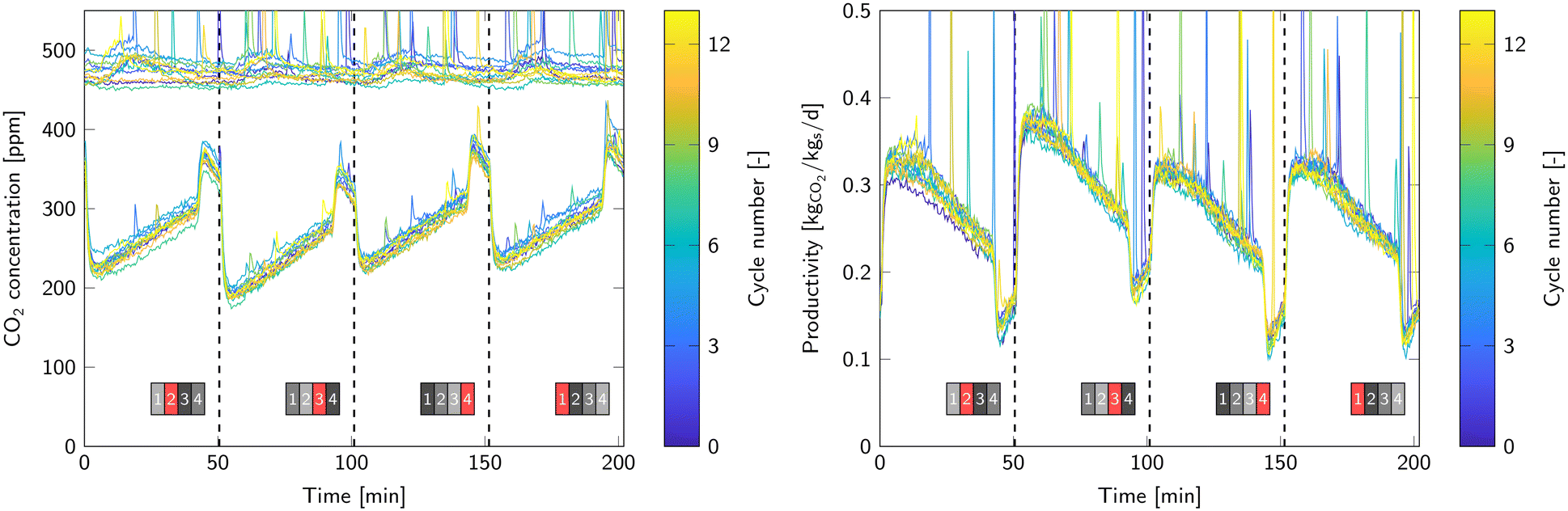 | ||
| Fig. 10 Inlet and outlet CO2 concentration profiles (left). The collection of graphs on the top are the ingoing concentration and the bottom graphs are the outgoing concentration. Overall productivity corresponding to the inlet and outlet concentration profiles (right). | ||
The overall capture efficiency is 42%, which leads to a productivity of 0.27 kgCO2 kgs−1 d−1 or 1.31 kgCO2 d−1. This is 5.5% lower than calculated via the breakthrough curves in Table 2. The difference is most likely caused by air that passes through the barriers in the air inlet/air outlet segments (Fig. 4). These barriers separate the air inlet of one reactor with the outlet of the reactor above. Some air leaks through the barriers and enters the gas outlet without passing through a reactor.
Effect of purge gas
The majority of the experimental work included a steam purge to enhance the desorption rate of CO2. Compared to a situation without a purge, it leads to an additional energy penalty to generate overheated steam, but also increases the productivity. Experiments with a steam purge are already discussed in previous chapters. In this section, we compare these results to experiments without a purge. All other operational parameters remain identical and can be found in Table 2 in ESI4.2.†The average working capacity drops from 0.92 molCO2 kgs−1 to 0.81 molCO2 kgs−1 without the use of a steam purge. This means that the productivity decreases from 0.29 kgCO2 kgs−1 d−1 to 0.26 kgCO2 kgs−1 d−1 (Fig. 11). The experiments without purge gas directly followed the experiments with a steam purge. An immediate drop in working capacity is observed. For reactor 4, this drop in performance is much less than for the other reactors. This is due to the higher desorption pressure caused by small leakages. These leakages result in an additional gas flow through the reactor, which makes a purge less effective. Therefore, this reactor is neglected in this comparison.
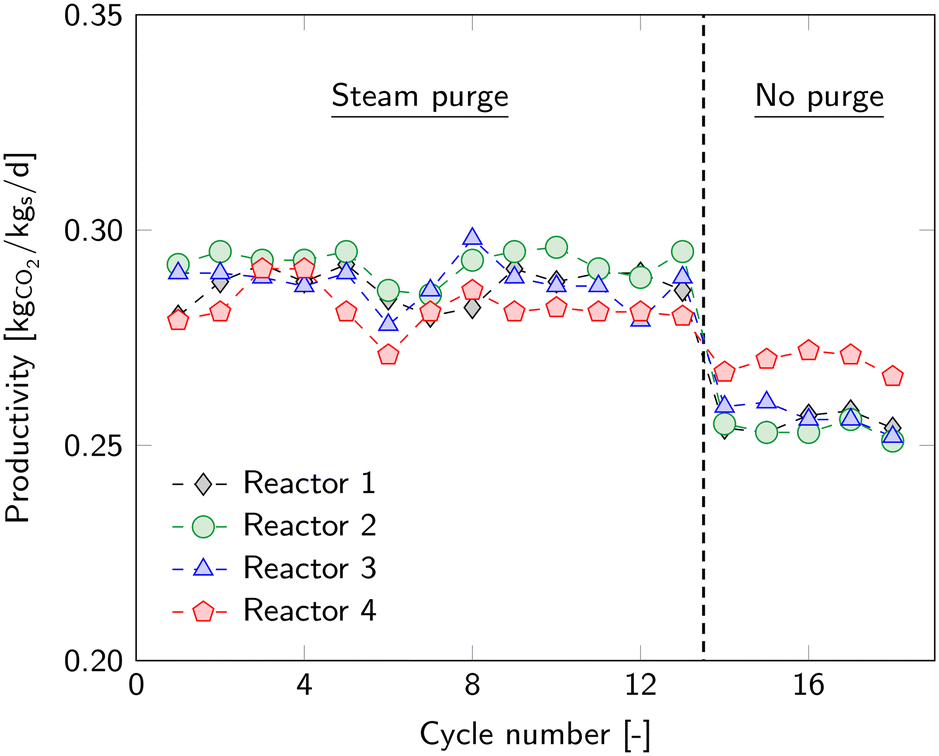 | ||
| Fig. 11 Productivity of all cycles and each reactor with a steam purge and without a steam purge. | ||
The enhanced desorption by means of the steam purge causes a lower CO2 loading of the sorbent at the end of desorption, i.e. beginning of adsorption. This creates a higher adsorption rate at the beginning of the adsorption step, which is also reflected in the breakthrough curves (Fig. 12). The figure shows the average breakthrough curve of all cycles including the standard deviation. At the beginning, a higher removal rate is achieved when desorbing with a steam purge. Although the curves seem to differ only slightly, the experiments without purge result in a 12% lower working capacity. The difference at the end of adsorption is mainly due to a slightly lower ingoing CO2 concentration for the experiments without purge.
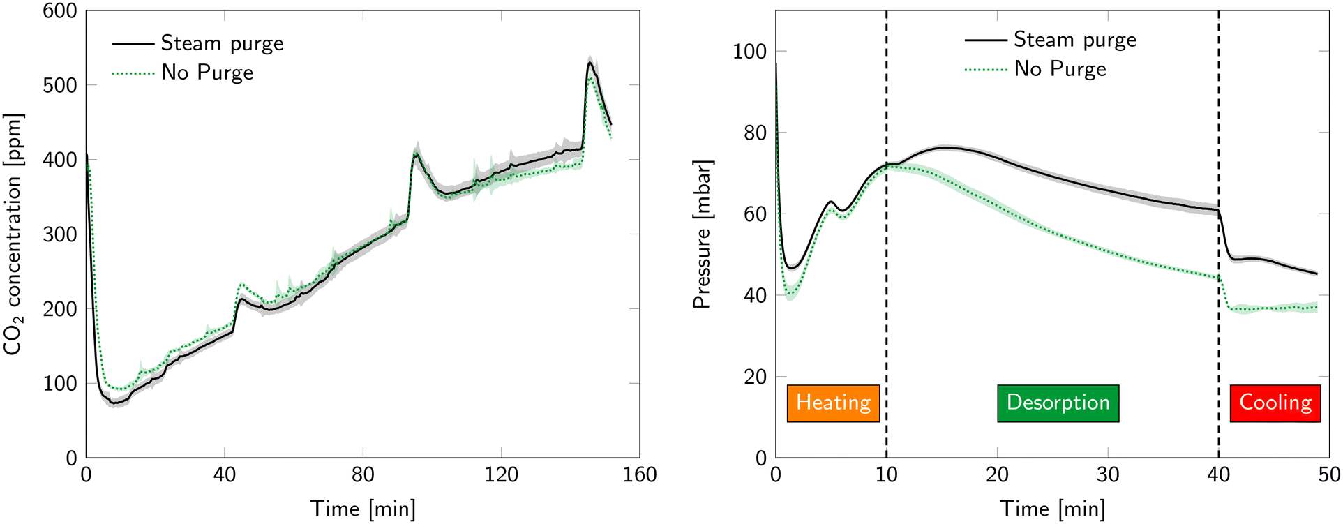 | ||
| Fig. 12 Comparison of breakthrough curves (left) and desorption pressure (right) with and without a steam purge. The shaded area represent standard deviation between cycles. | ||
The desorption pressure is also influenced by the purge gas flowrate (Fig. 12). The most notable difference occurs in the desorption step. Introducing a purge gas combined with the enhanced desorption rate increases the gas flow through the vacuum pump and therefore also the pressure. Also during heating and cooling, the pressure is lower without a purge gas (even though in both cases there is no purge present at that time). This is related to water condensation in the tubing between the reactors and the vacuum pump. This slowly evaporates again during heating and cooling which increases the pressure.
The amount of energy that is required to operate this TVSA process without a purge gas is 13.8 MJ kgCO2−1. That is 5% lower than using steam as purge gas while keeping all other parameters constant (Fig. 13). The energy distribution shows that a change of purge gas flowrate does not only alter the energy requirements of the purge gas. It also reduces the CO2 working capacity and consequently increases the sensible heat requirements per kilogram of CO2 produced. Furthermore, it reduces the capture efficiency and worsens the CO2 selectivity, which increases feed compression costs and H2O reaction heat requirements, respectively. Finally, it reduces the gas flow during desorption, which is beneficial for the energy penalty of creating vacuum. Overall, an energy reduction of 5% is obtained when operating without a steam purge, while the purge was responsible for 12% of the energy requirement. This shows that changing a single parameter affects nearly all aspects of the TVSA cycle. Therefore, it is very complex to determine or predict quantitatively, and sometimes even qualitatively, the impact of changing a single parameter without experimental results or a well-validated system model.
 | ||
| Fig. 13 Comparison of energy duty and productivity for a TVSA cycle with a steam purge and without a purge. The values of each contribution can be found in ESI4.2.† | ||
Effect of cycle length
The cycle length is the second operational parameter that is varied. Experimental campaigns that span multiple days are conducted using three different cycle durations. This section compares these campaigns based on the overall key performance indicators. Table S3 in ESI4.3† gives an overview of the operational conditions of these experiments. For a more detailed analysis, the reader is referred to the same appendix.The ratio between adsorption time and regeneration time is fixed by the number of reactors. Therefore, either the duration of the adsorption step or desorption step can be varied. We choose to fix the desorption time at 15 and 45 min, which leads to an adsorption time of 107 and 197 min, respectively. A desorption time of 30 min was already performed using the ‘design’ parameters. The duration of the evacuation, heating and cooling steps remain the same in all experiments. Fig. 14 shows the resulting time-based control schedules.
 | ||
| Fig. 14 Time-based control schedule for each of the experimental campaigns. The 'design' parameters are the same as in the schedule in Fig. 3. | ||
The goal of a longer adsorption time is to increase the working capacity and therefore reduce the number of temperature swings to capture the same amount of CO2. The CO2 working capacity reduces from 0.92 molCO2 kgs−1 for the design case to 0.67 molCO2 kgs−1 for the short cycle and increases to 1.05 molCO2 kgs−1 for the long cycle (Table 3). On the other hand, the productivity decreases with increasing cycle length. From the breakthrough curves (Fig. 7 and 12) it already shows that the adsorption rate decreases as the adsorption step progresses. Therefore, a process with a short adsorption step has a high productivity. However, this effect seems to flatten when going towards shorter cycle times. Then, the limitation lies in the regeneration phase. The time it takes for heating and cooling can be considered as downtime. In this period, there is no CO2 capture from air and there is barely any CO2 production. Since these durations for heating and cooling are fixed, the fraction of overall downtime increases for a shorter cycle. This essentially means that the desorption is too short to sufficiently regenerate the sorbent. Then, the sorbent loading at the beginning of adsorption is relatively high, which is then the limiting factor for the adsorption rate. The maximum productivity of this compact DAC pilot unit is 0.30 kgCO2 kgs−1 d−1 or 1.44 kgCO2 d−1.
| Parameter | ‘Short’ cycle | ‘Design’ cycle | ‘Long’ cycle |
|---|---|---|---|
| Cycle duration (min) | 142 | 202 | 262 |
| CO2 working capacity (molCO2 kgs−1) | 0.67 | 0.92 | 1.05 |
| H2O working capacity (molH2O kgs−1) | 0.98 | 1.04 | 1.48 |
| CO2/H2O selectivity (molCO2 molH2O−1) | 0.69 | 0.88 | 0.71 |
| Productivity (kgCO2 d−1) | 1.44 | 1.38 | 1.13 |
| Productivity (kgCO2 kgs−1 d−1) | 0.30 | 0.29 | 0.25 |
| Purge gas ratio (molpurge molCO2−1) | 1.06 | 1.56 | 2.04 |
| Capture efficiency (%) | 44 | 42 | 36 |
| Energy duty (MJ kgCO2−1) | 16.4 | 14.5 | 14.9 |
Operating with a longer or shorter cycle time does not decrease the energy duty compared to the design operating conditions. The energy duty increases from 14.5 MJ kgCO2−1 to 16.4 MJ kgCO2−1 for a shorter cycle time (Table 3). That is a 13% increase in energy duty while the productivity only increases by 4%. A shorter cycle length results in a trade-off between productivity and energy duty. Although it seems more favourable to use the ‘design’ cycle length, an economic assessment is required to provide a definitive answer. For the long cycle time, the energy duty slightly increases to 14.9 MJ kgCO2−1 while the productivity decreases by 12%. Therefore, a longer cycle length is not beneficial in terms of both key performance indicators.
Sensible heat is the dominant factor in all cases ranging from 44% of the total energy requirement for the long cycle to 60% for the short cycle (Fig. 15). The lower working capacity for a shorter cycle requires more temperature swings to capture the same amount of CO2; hence, it increases the sensible heat requirements.
 | ||
| Fig. 15 Comparison of energy duty distribution and productivity for three cycle durations. The numeric values of each energy contribution can be found in Table S3 in ESI4.3.† | ||
Steam generation costs more energy for a longer cycle time. This means that more steam is required to desorb the same amount of CO2. It is a consequence of the applied constant steam flowrate, which becomes less effective near the end of desorption, especially for a long desorption time. This could also be a result of a possible mismatch between adsorption time and regeneration time, determined by the number of reactors. It seems not necessary to desorb for 45 minutes in the long cycle, while a desorption time of 15 minutes seems not long enough in the short cycle. The constant steam flowrate also causes the vacuum compression costs to increase for a longer cycle time. Other contributors to vacuum compression (product gas and co-adsorbed H2O) do not change significantly between the experimental campaigns.
Feed compression increases when increasing the cycle time due to a lower capture efficiency. The capture rate decreases as adsorption progresses and a longer adsorption step will consequently result in a lower capture efficiency. The capture efficiencies for the short, design and long cycle are 44, 42 and 36%, respectively. However, even for the long cycle, feed compression is only a small contributor to the overall energy requirements.
The relative humidity was low during all experiments, which resulted in a very low energy requirement for H2O co-adsorption. For equal ambient conditions, the selectivity towards H2O should be higher when increasing the cycle length. Then, the CO2 working capacity increases, but the H2O working capacity is the same, since H2O adsorption is much faster than CO2 adsorption. However, the relative humidity was higher during the long cycle experiments compared to the other experiments. Therefore, the selectivity towards H2O is actually lower (0.71 vs. 0.88 molCO2 molH2O−1) and the energy duty for H2O co-adsorption is higher.
Together these results show that the productivity can be increased by decreasing the cycle length. Decreasing the cycle length further than the ‘short’ cycle will not result in a much higher productivity due to the downtime of the process during heating and cooling. This increase in productivity also results in a higher energy duty, which means a trade-off between operational expenditure and capital expenditure. An increase in cycle length is disadvantageous for both productivity and energy duty.
Conclusions
This research focused on the system performance analysis for a kg-scale DAC pilot unit using solid sorbent technology with a steam-assisted temperature-vacuum swing adsorption process. Four identical shallow fixed bed reactors allow for a continuous production of CO2. Reproducible results were obtained for the complete experimental dataset, which spanned several weeks.The system has a CO2 production capacity of 1.3 kgCO2 d−1, which corresponds to 0.27 kgCO2 kgs−1 d−1, with an energy consumption of 14.5 MJ kgCO2−1. By reducing the cycle length, the productivity was increased to 0.30 kgCO2 kgs−1 d−1, but comes at a cost of 16.4 MJ kgCO2−1.
The analysis of energy duty shows that gas–solid contacting is not necessarily a large energy contributor. Furthermore, the sensible heat requirement of the gas–solid contactor is the largest energy contributor. Sorbent circulation from an adsorption compartment to a separate desorption compartment can therefore potentially reduce the total energy demand by 30%. Desorption of co-adsorbed H2O can account for a much larger energy penalty compared to CO2 desorption, and is mostly depending on the relative humidity. The exact magnitude of H2O co-adsorption is not entirely clear from the experimental results and requires more attention in future research. However, it is clear that the climate conditions, and therefore geographic location, is surely an important aspect in the viability of a DAC process.
Implementing the identified optimization strategies to the current process can already reduce the energy consumption to 8.1 MJ kgCO2−1. Further optimization of the operational parameters and introduction of a heat pump potentially reduces the energy demand to 5.1 MJ kgCO2−1 without a significant decrease in productivity.
Author contributions
Conceptualization: H. M. S., D. W. F. B.; methodology: H. M. S., D. W. F. B.; software: H. M. S.; validation: H. M. S.; formal analysis: H. M. S.; investigation: H. M. S.; writing – original draft: H. M. S.; writing – review & editing: D. W. F. B.; visualization: H. M. S.; supervision: D. W. F. B.; project administration: H. M. S., D. W. F. B.; funding acquisition: D. W. F. B.Conflicts of interest
There are no conflicts to declare.Acknowledgements
The authors acknowledge Benno Knaken, Johan F. H. Agterhorst and Ronald A. Borst (Sustainable Process Technology group, University of Twente) for their craftsmanship and efforts in the construction of the pilot unit. This research was funded by NORTH-WEST EUROPEINTERREG, grant number NWE 639 as part of the IDEAproject (Implementation and development of economic viablealgae-based value chains in North-West Europe).References
- Climate change 2022: Mitigation of Climate Change. Contribution of Working Group III of the Sixth Assessment Report of the Intergovernmental Panel on Climate Change, 2022, DOI:10.1017/9781009157926.
- J. G. Speight, Handbook of Industrial Hydrocarbon Processes, Gulf Professional Publishing, Boston, 2019 Search PubMed.
- J. P. Lange, Energy Environ. Sci., 2021, 14, 4358 RSC.
- K. Ragaert, L. Delva and K. Van Geem, Waste Manage., 2017, 69, 24 CrossRef CAS PubMed.
- M. Erans, E. S. Sanz-Pérez, D. P. Hanak, Z. Clulow, D. M. Reiner and G. A. Mutch, Energy Environ. Sci., 2022, 15, 1360 RSC.
- Orca: the first large-scale plant, https://climeworks.com/plant-orca, (accessed: December 2023).
- Key features of CE's DAC technology, https://carbonengineering.com/our-technology/, (accessed, July 2022).
- D. W. Keith, G. Holmes, D. St. Angelo and K. Heidel, Joule, 2018, 2, 1573 CrossRef CAS.
- Climeworks takes another major step on its road to building gigaton DAC capacity, https://newsroom.climeworks.com/196012-climeworks-takes-another-major-step-on-its-road-to-building-gigaton-dac-capacity, (accessed December 2023).
- C. J. E. Bajamundi, J. Koponen, V. Ruuskanen, J. Elfving, A. Kosonen, J. Kauppinen and J. Ahola, J. CO2 Util., 2019, 30, 232 CrossRef.
- M. M. Sadiq, M. P. Batten, X. Mulet, C. Freeman, K. Konstas, J. I. Mardel, J. Tanner, D. Ng, X. Wang, S. Howard, M. R. Hill and A. W. Thornton, Adv. Sustainable Syst., 2020, 4, 2000101 CrossRef CAS.
- H. M. Schellevis, T. N. van Schagen and D. W. F. Brilman, Int. J. Greenhouse Gas Control, 2021, 110, 103431 CrossRef CAS.
- M. Schellevis, T. Jacobs and W. Brilman, Front. Chem. Eng., 2020, 2 DOI:10.3389/fceng.2020.596555.
- A. Sinha, L. A. Darunte, C. W. Jones, M. J. Realff and Y. Kawajiri, Ind. Eng. Chem. Res., 2017, 56, 750 CrossRef CAS.
- A. R. Sujan, S. H. Pang, G. Zhu, C. W. Jones and R. P. Lively, ACS Sustainable Chem. Eng., 2019, 7, 5264 CrossRef CAS.
- W. Zhang, H. Liu, C. Sun, T. C. Drage and C. E. Snape, Chem. Eng. Sci., 2014, 116, 306 CrossRef CAS.
- Q. Yu and W. Brilman, Appl. Sci., 2020, 10, 1080 CrossRef CAS.
- N. McQueen, K. V. Gomes, C. McCormick, K. Blumanthal, M. Pisciotta and J. Wilcox, Prog. Energy, 2021, 3, 032001 CrossRef.
- M. Fasihi, O. Efimova and C. Breyer, J. Cleaner Prod., 2019, 224, 957 CrossRef CAS.
- R. P. Wijesiri, G. P. Knowles, H. Yeasmin, A. F. A. Hoadley and A. L. Chaffee, Processes, 2019, 7, 503 CrossRef CAS.
- W. R. Alesi and J. R. Kitchin, Ind. Eng. Chem. Res., 2012, 51, 6907 CrossRef CAS.
- M. J. Bos, T. Kreuger, S. R. A. Kersten and D. W. F. Brilman, Chem. Eng. J., 2019, 377, 120374 CrossRef CAS.
- A. Sayari, A. Heydari-Gorji and Y. Yang, J. Am. Chem. Soc., 2012, 134, 13834 CrossRef CAS PubMed.
- Q. Yu, J. D. L. P. Delgado, R. Veneman and D. W. F. Brilman, Ind. Eng. Chem. Res., 2017, 56, 3259 CrossRef CAS.
- E. Sonnleitner, G. Schöny and H. Hofbauer, Biomass Convers. Biorefin., 2018, 8, 379 CrossRef CAS.
- M. L. Gray, J. S. Hoffman, D. C. Hreha, S. W. Hedges, K. J. Champagne and H. W. Pennline, Energy Fuels, 2009, 23, 4840 CrossRef CAS.
- G. P. Knowles and A. L. Chaffee, Energy Procedia, 2017, 114, 2219 CrossRef CAS.
- L. A. Darunte, K. W. Walton, D. S. Scholl and C. W. Jones, Curr. Opin. Chem. Eng., 2016, 12, 82 CrossRef.
- R. Veneman, N. Frigka, W. Zhao, Z. Li, S. Kersten and W. Brilman, Int. J. Greenhouse Gas Control, 2015, 41, 268 CrossRef CAS.
- C. Drechsler and D. A. Agar, Energy, 2020, 192, 116587 CrossRef CAS.
- J. Young, E. García-Díez, S. Garcia and M. van der Spek, Energy Environ. Sci., 2021, 14, 5377 RSC.
- T. N. van Schagen, P. J. van der Wal and D. W. F. Brilman, Chem. Eng. J. Adv., 2022, 9, 100187 CrossRef CAS.
- C. Arpagaus, F. Bless, M. Uhlmann, J. Schiffmann and S. S. Bertsch, Energy, 2018, 152, 985 CrossRef CAS.
Footnote |
| † Electronic supplementary information (ESI) available. See DOI: https://doi.org/10.1039/d3re00460k |
| This journal is © The Royal Society of Chemistry 2024 |