DOI:
10.1039/D4RA04105D
(Paper)
RSC Adv., 2024,
14, 27488-27503
LaCo0.2Fe0.8O3 perovskites doped with natural Ca2+ as bifunctional electrocatalysts for oxygen evolution and reduction reactions
Received
7th June 2024
, Accepted 13th August 2024
First published on 29th August 2024
Abstract
Perovskite oxides are promising electrocatalysts for various energy applications due to their exceptional catalytic activity, flexible architecture, and low cost. In this study, LCFO was doped with different ratios of Ca2+ from eggshells, resulting in dual-purpose electrocatalysts for oxygen reduction and evolution processes. The nanoparticles were characterized using various techniques, including Brunauer–Emmett–Teller analysis and XRD. Results clarified the relative surface area and roughness, increasing with Ca2+ doping. LCFO also demonstrated highly magnetic properties, improved charge transfer, catalytic activity, and long-term durability. The results demonstrated the perovskite's cost-effectiveness as a bifunctional electrocatalyst, and the role of Ca2+ in enhancing its properties. La0.6Ca0.4Co0.2Fe0.8O3(LCCFO-0.4) showed higher magnetic properties (Ms = 13.36 emu g−1 and Mr = 2.54 emu g−1). The LCFO sample showed a current density of 5.13 mA cm−2 and 3 mA cm−2 for OER and ORR respectively, at Eonset 1.7 V and 0.57 V (vs. RHE). The LCFO electrochemical active surface area is 0.033 cm2
1. Introduction
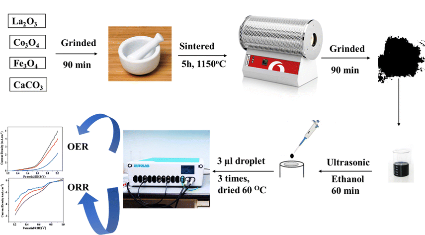
Population growth has led to increased energy consumption, resulting in more use of fossil fuels and negative environmental effects.1,2 To combat climate change, renewable energy sources must be replaced with sustainable alternatives.3,4 Energy storage and conversion technologies must be developed to provide energy when needed.5 Hydrogen could replace the current fossil fuel grid due to its high mass-energy density and low greenhouse gas emissions.6 To avoid pollution, electrochemical energy conversion and storage technologies, such as water separation systems, regenerative fuel cells, and metal–air batteries, must be advanced.7,8 Electrochemical water splitting, a recent advancement, is superior to traditional methods due to its separate production of oxygen and hydrogen, no need for purification, and no CO2 emissions.9,10 The highest efficiency towards the oxygen reduction reaction (ORR) can be found in platinum and palladium catalysts, even though their oxygen evolution reaction (OER) activity is restricted, so the employed catalyst is a promising area of research.11,12 The most often used OER catalysts are IrO2 and RuO2, yet they have poor ORR efficiency.13 The main goal of electrochemical energy storage and conversion technologies is to improve the efficiency of noble metal catalysts, which are costly due to their scarcity and instability, enabling their use as both ORR and OER catalysts.14,15 Much effort is being put into developing novel electrocatalytic materials, particularly those working as bifunctional electrocatalysts that achieve high performance due to multiple site functionalities, and are known for their low cost, stability, durability and activity.16 ABO3 is one of the most targeted materials for electrocatalysts due to the formula of perovskite oxide minerals formula, which is ABO3. A is an alkaline earth metal or lanthanide element known for being environmentally friendly, as well as having unique characteristics such as electronic, catalytic, magnetic, and ionic properties. B is a transition metal (TM) element (Co, Mn, Ni, Fe, Ti, and Cr).17 They are inexpensive, simple to prepare, and have good electrochemical activity in a variety of applications.18 Unfortunately, the electrocatalytic activity, low conductivity, and few active sites are the limitations of pristine LaFeO3 perovskite.19 Numerous strategies have been developed to enhance the activity of (ORR) and (OER) activities in perovskite structures.20 These include altering the structure and morphology to increase active sites and surface area, improving inherent properties, and optimizing the electronic structure through doping with alkali metal, transition metal (TM), or rare earth elements.21 Doping is a popular and efficient method for improving electrocatalytic performance. Perovskite structures can be enhanced by adding cations to the A or B sites, controlling their oxidation state and oxygen vacancies in the B-site.22 This treatment generates oxygen vacancies, which serve as active sites and have significant intrinsic activity.23 Researchers concluded that the ORR process involves oxygen diffusion, followed by oxygen adsorption on the catalyst's surface and that the pathway for electron transfer from the anode to the oxygen (O2 molecules) starts.14 This causes the formation of hydroxide ions, which provide the alkaline electrolyte with a catalytic surface. Similarly, the OER process is highly complex because of the numerous paths of electron transport mechanisms. Electrocatalysis requires an effective electron stream to produce significant current, and the electrical conductivity of electrocatalysts is crucial.24 Perovskite oxides have poor electrical conductivity at ambient temperatures.25 A study on LaFeO3 doped with Co as a Fe-substituent and Eggshell as a Ca-source showed that co-doping in the LaFeO3 matrix improves ORR and OER performance by increasing the electro-catalyst electrical conductivity over undoped LaFeO3.26 According to reports, the eggshell's chemical composition is composed of 94% calcium carbonate, 1% calcium phosphate, 1% magnesium carbonate, and 4% organic content by weight.27 Our choice to use LCFO perovskite as magnetic nanoparticle give us the chance of easy physical separation (magnetic decantation) of the nanoparticles from water after carrying out the experiments. Therefore, one could reuse the nanoparticles more than one time and we could in our future work investigate the reusability of such compounds. In a trial to decrease the cost of perovskite using natural sources such as CaCO3 eggshell, this work was carried out using the standard ceramic method for preparation. One of our objectives is to thoroughly investigate how Ca content will affect the electrochemical performance of such perovskite (Fig. 1).
 |
| | Fig. 1 A schematic diagram of the synthesis, electrode preparation, and application. | |
2. Materials and methods
Without undergoing any additional purification, the metal precursors La2O3 (99.9%, Alfa Aesar), Fe3O4 (99.9%, Alfa Aesar), and Co3O4 (99.9%, Alfa Aesar) were utilized exactly as supplied. Ethanol (99.5%, Alfa Aesar) and CaCO3 are used from an eggshell source and treated as mentioned below.
2.1. Sample preparation
2.1.1. Eggshell CaCO3 preparation. Eggshells were collected from markets in Beni-Suef governorate, Egypt. The sample membranes were removed and then repeatedly cleaned with double-distilled water to get rid of any organic membrane residue or impurities from the shells' surfaces. The washed samples were dried in an oven for 2 hours at 70 °C, and the dried samples were crushed by mortar and ground in a blender several times, sieved to get a homogenous distribution of powdered samples. This was followed by an etching step in which 20 g of the dried powder was immersed in a solution of 40 mL HNO3 (55%), 160 mL DI water, then thoroughly washed with 100 mL DI water, and finally dried.
2.1.2. LaCo0.2Fe0.8O3 preparation. The metal oxides stoichiometric ratios were computed to produce LaCoxFe1−xO3 (x = 0.2, denoted as LCFO). The powder was well-ground for 2 hours. The mixed precursors for perovskite synthesis were sintered in a tube furnace in alumina crucibles at 1150 °C for 5 h with a heating and cooling rate of 2 °C min−1. Once the samples attained room temperature, they were ground with an agate mortar, collected, characterised, and tested for application.
2.1.3. La1−xCaxCo0.2Fe0.8O3 preparation. The weight ratio of the mixed oxides, in addition to CaCO3 from Eggshell, was considered for perovskite synthesis with two different Ca ratios: 0.1 (to get La0.9Ca0.1Co0.2Fe0.8O3) and 0.4 (to get La0.6Ca0.4Co0.2Fe0.8O3) denoted as LCCFO-0.1 and LCCFO-0.4, respectively. The same preparation conditions and steps were repeated as mentioned above for LCFO.
2.1.4. Drop casting preparation. After 60 minutes of sonication, 10 mg of the prepared materials were mixed with 400 mL of ethanol and 2% Nafion. A micropipette was used to take a 3 μL droplet that was taken and place it over a glassy carbon electrode of 3 mm diameter, dried at 60 °C.
2.2. Samples characterization
2.2.1. X-ray diffractometer. X-ray diffraction patterns were obtained using Cu-Kα radiation (wavelength λ = 1.54045 Å) at an accelerating voltage of 40 kV, a current of 35 mA, a scan range of (10–80) degrees, and a scan step of 0.04° from (PANalytical Empyrean, Netherlands). XRD was used to assess the purity phase and crystallinity of the produced samples.
2.2.2. Field-emission scanning electron microscopy. (FESEM) of Quanta FEG 250, Switzerland, was utilized to capture micrographs of the surface morphological features.
2.2.3. Brunauer–Emmett–Teller (BET). Micromeritics Tri Star II, using N2 was used to study adsorption and desorption curves. The surface area as well as the pore size distribution were calculated.
2.2.4. UV-spectrophotometer. The samples' optical spectra were measured with a 1 nm step between 200 and 1000 nm using PerkinElmer UV Win Lab 6.0.4.0738/1.61.00 Lambda 900. For each sample, Tauc plots were used to establish the optical band gap based on linear extrapolation.
2.2.5. Electrical properties measurements. Using a press with a pressure of 1.5 × 10⁶ N m−2, pellets with a diameter and thickness of 10.1 mm and 1.6 mm, respectively, were created from the ground powder. The pellet's surfaces were coated using conductive silver paste, and the conduction was evaluated and checked to be ohmic. At room temperature, the Hioki LCR meter (3532, Japan) was used after being calibrated to collect data on capacitance, resistance, and losses at frequencies between 50 Hz and 5 MHz.
2.2.6. Magnetic properties measurements. The vibrating sample magnetometer (VSM LakeShore 7410, USA) was employed to test the magnetization against magnetic field at room temperature, with a maximum applied field of 20 kOe.
2.2.7. Electrochemical measurements. The electrochemical studies employed a three-electrode cell setup with an Autolab PGSTAT302N potentiostat (Metrohom), working electrodes (prepared materials), reference electrode (Saturated Calomel Electrode, SCE), and counter electrode (platinum wire). A variety of catalysts were used as working electrodes for ORR and OER uses. The electrolyte was purged with an oxygen gas flow for thirty minutes before the ORR electrochemical testing. The NOVA program version 1.11 was used to record all measurements, and a 0.1 M solution was used for each measurement. Electrochemical testing included linear sweep voltammetry (LSV), chronopotentiometry, and electrochemical impedance spectroscopy (EIS). The LSV was carried at fixed scan rates of 5 mV s−1 via a potential range from 0 up to 1.2 and 0.2 to −0.8 V vs. the saturated calomel electrode (SCE) for OER and ORR, respectively. All samples were tested for 18![[thin space (1/6-em)]](https://www.rsc.org/images/entities/char_2009.gif) 000 seconds of chronopotentiometry long-term stability to produce 1 mA vs. RHE for OER and ORR, respectively. The EIS was conducted in the range of 5–100000 Hz with an amplitude of 10 mV.
000 seconds of chronopotentiometry long-term stability to produce 1 mA vs. RHE for OER and ORR, respectively. The EIS was conducted in the range of 5–100000 Hz with an amplitude of 10 mV.
2.2.8. Contact angle. Measurements of contact angle was carried out to check the surface wettability by creating films via spreading a portion of the catalyst to make a layer over double-phase tape stacked over a glass slide as a supporting medium. Then, using a micro syringe, a 5 mL droplet of deionized (DI) water was placed on the sample's surface. The angle of water contact, or WCA (Q), was determined by the sessile drop technique utilizing an optical contact angle meter (CAM 200; KSV Instruments). The droplet's image was taken to calculate the angle that developed at the contact between liquid and solid. For every sample, the WCA was measured three times, and the average value was determined.
3. Results and discussion
3.1. Structural analysis
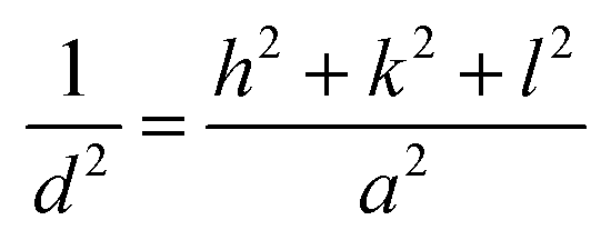
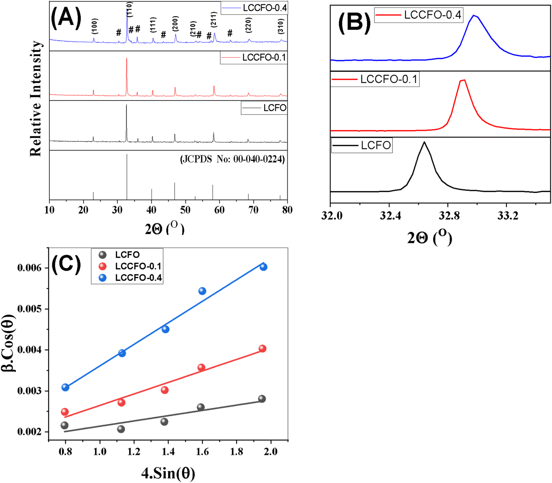
Fig. 2 shows the XRD diffraction patterns of the different prepared samples. It was matched with [JCPDS No. 00-040-0224] of lanthanum cobalt orthoferrite. The cubic phase LaCo0.2Fe0.8O3 appears based on the peaks, with a space group of Pm![[3 with combining macron]](https://www.rsc.org/images/entities/char_0033_0304.gif) m. The XRD main patterns of the LaCo0.2Fe0.8O3 samples showed identical peaks of LaCo0.2Fe0.8O3, with noticeable shifting for higher values. The reflections appeared at 2θ = 22.8°, 32.6°, 40.2°, 46.7°, 52.8°, 58.1°, 68.2°, and 77.6° with miller indices (100), (110), (111), (200), (211), (220), and (310) planes. The presence of additional peaks of low intensity did not match with [JCPDS no. 00-040-0224], and others matched with [JCPDS no. 79-1774].27 Ascribed to CoFe2O4 marked with a hash sign in the XRD graph have peaks values at 2θ = 30.1°, 35.4°, 37.1°, 43.1°, 53.4°, and 62.5° related to Miller indices (104), (113), (006), (024), (214), and (208) planes, respectively. It is confirmed that two phases (LaCo0.2Fe0.8O3 and CoFe2O4) were present in earlier published work.28 Doping the LCFO matrix with a certain amount of Ca2+ causes a clear shift in the peaks with intensity reduction.28 The absence of any individual characteristic peaks of the Co or Ca main peaks may be due to the small constant weight ratio and successful incorporation of the metal cations into the cubic matrix of LCFO. The essential reflections (110), (200), and (211) confirm the cubic structure of all samples. A further rise in Ca2+ ion content showed a slight deviation in all the peaks, with reduced intensities and broadening of the peaks, which confirms the successfully prepared samples. The crystallite size of the samples is determined by the line broadening of the 100% strong peak of the XRD pattern (110). Using eqn (1) to calculate the variation of the lattice parameters.29
m. The XRD main patterns of the LaCo0.2Fe0.8O3 samples showed identical peaks of LaCo0.2Fe0.8O3, with noticeable shifting for higher values. The reflections appeared at 2θ = 22.8°, 32.6°, 40.2°, 46.7°, 52.8°, 58.1°, 68.2°, and 77.6° with miller indices (100), (110), (111), (200), (211), (220), and (310) planes. The presence of additional peaks of low intensity did not match with [JCPDS no. 00-040-0224], and others matched with [JCPDS no. 79-1774].27 Ascribed to CoFe2O4 marked with a hash sign in the XRD graph have peaks values at 2θ = 30.1°, 35.4°, 37.1°, 43.1°, 53.4°, and 62.5° related to Miller indices (104), (113), (006), (024), (214), and (208) planes, respectively. It is confirmed that two phases (LaCo0.2Fe0.8O3 and CoFe2O4) were present in earlier published work.28 Doping the LCFO matrix with a certain amount of Ca2+ causes a clear shift in the peaks with intensity reduction.28 The absence of any individual characteristic peaks of the Co or Ca main peaks may be due to the small constant weight ratio and successful incorporation of the metal cations into the cubic matrix of LCFO. The essential reflections (110), (200), and (211) confirm the cubic structure of all samples. A further rise in Ca2+ ion content showed a slight deviation in all the peaks, with reduced intensities and broadening of the peaks, which confirms the successfully prepared samples. The crystallite size of the samples is determined by the line broadening of the 100% strong peak of the XRD pattern (110). Using eqn (1) to calculate the variation of the lattice parameters.29| |
 | (1) |
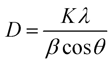
where the d refers to the inter-planar distance and (hkl) represents Miller indices. The substitution mechanism between La3+ and Ca2+ is a function of the metal's radii; the closer the radii, the better substitution occurs. The reported values of La3+ and Ca2+ ions are 1.03 Å (ref. 30) and 1.00 Å.31 Based on Scherrer's eqn (2), the crystallite size was computed.| |
 | (2) |
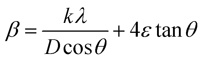
where D denotes the size of the crystallite, λ the X-ray target's wavelength, k the shape factor (∼0.94), θ the diffraction angle, and β corrected full width at half maximum “in radians”. The various sample results are tabulated in Table 1. The estimated values showed a clear decrease in the crystallite size. Increasing the Ca2+ ratio hinders the growth of crystal grains during the preparation process (working as a growth inhibitor).32 The reported values of the unit cell volume decreased with the addition of Ca2+ ions. The principle states that replacing larger ions with smaller ones increases the values of interplanar distances and decreases the lattice volume and parameter (a). All the reported data refers to the decrease in compressive strain due to the substitution process. Williamson–Hall (W–H relation) was used to get the lattice microstrain values due to its importance in the XRD analysis. Microstrain is mainly responsible for the peak broadening. Lattice strain, which results from crystal imperfections such as lattice dislocations, is a measurement of the lattice constant distribution. We estimated the crystallite size and lattice strain using the W–H method of XRD data processing. Fig. 2c shows the W–H plot between 4sinθ on the X-axis and βcosθ on the Y-axis. The slope equals the microstrain and the intercept = 0.94λ/Dcosθ. The strain caused by crystal imperfection and distortions in the prepared samples was calculated based on eqn (3).
| |
 | (3) |
ε: is the microstrain. The structural parameter values are computed and listed in Table 1. The W–H analysis removes the strain role from the FWHM in the XRD peak, which results in slightly larger crystallite size values derived from the W–H analysis than those obtained using the Scherer formula. Also, comparing the two equations of Scherer's and W–H, the presence of a secondary term referring to the microstrain is the main reason behind the variance in the crystallite size values. As a result, the peak width obtained will be slightly less than what the Scherer formula takes into account. In the pure samples (host material), triple junctions, contact or sinter stresses, stacking faults, and coherency stresses are considered to be the origins of strain development. In addition, doping with small cations exerts a strain on the cubic lattice, as reported before. The dislocation density ((δ)lines m−2) is calculated from eqn (4).| |
 | (4) |
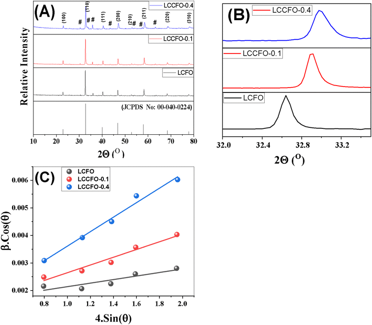 |
| | Fig. 2 (A) X-ray diffraction patterns of the synthesized materials, (a) [JCPDS No. 00-040-0224], (b) LCFO, (c) LCCFO-0.1, (d) and LCCFO-0.4. (B) Shows the highest peak matching with the JCPDS card and clear integration of the compounds. (C) Shows the W–H plot for all samples. | |
Table 1 XRD parameters of LCFO, LCCFO-0.1 and LCCFO-0.4. (a) Is the lattice parameter, V lattice volume, D is the theoretical density, δ the dislocation density
| Parameters |
ICDD card |
LCFO |
LCCFO-0.1 |
LCCFO-0.4 |
| acalculated, Å |
3.88 |
3.78 |
3.61 |
3.35 |
| Vcalculated, Å3 |
58.64 |
54.01 |
47.12 |
37.09 |
| Dcalculated, g cm−3 |
6.66 |
6.68 |
6.64 |
6.48 |
| Crystallite size Debye (nm) |
— |
42.49 |
32.86 |
23.45 |
| Crystallite size WH (nm) |
— |
148.1 |
116.7 |
96.1 |
| Micro-strain |
— |
15 × 10−4 |
12.4 × 10⁻⁴ |
9.77 × 10⁻⁴ |
| δ lines m−2 (×1014) |
— |
5.53 |
9.25 |
18.17 |
The density of dislocations, which are structural flaws in crystalline materials, has a significant impact on the characteristics of the material. Analysing the widening of diffraction peaks in the XRD pattern allows for the indirect estimation of dislocation density by XRD.25,33 Furthermore, dislocation density is one of the factors responsible for peak broadening.27,34,35
3.2. Surface morphology and elemental analysis
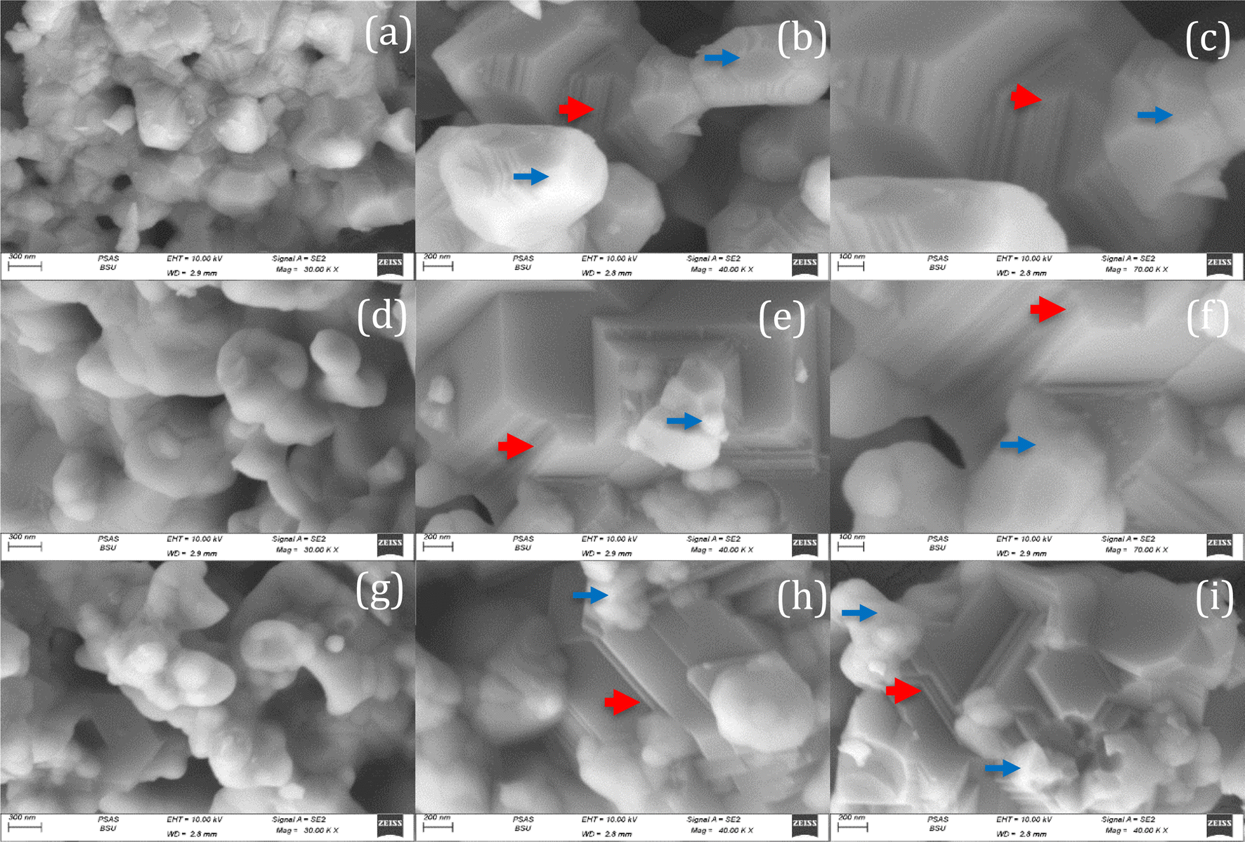
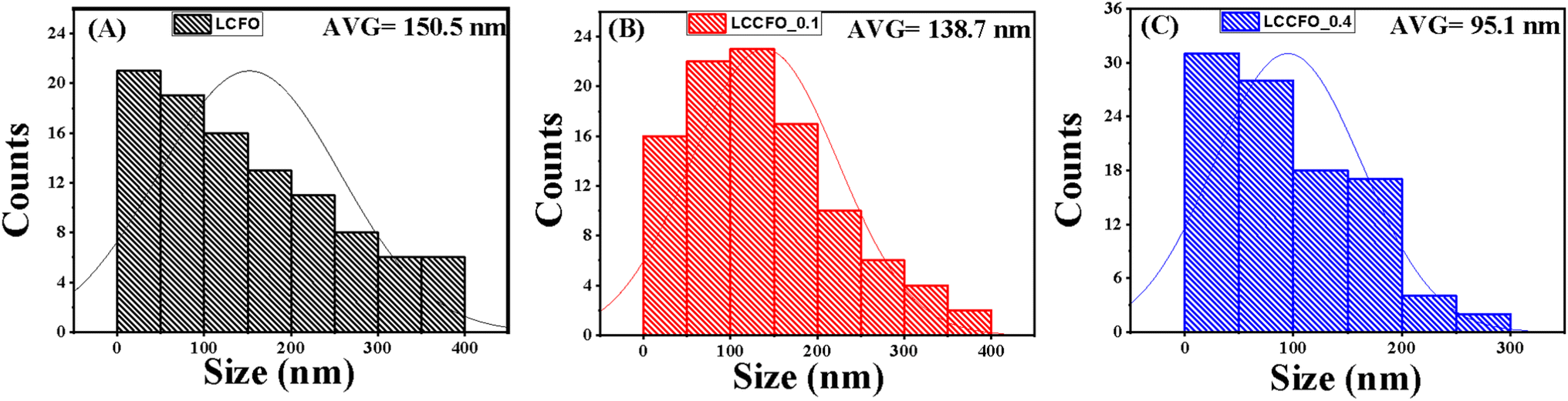
The FESEM micrographs of LCFO and their Ca-doped samples are shown in Fig. 3. Using field emission scanning electron microscope (FE-SEM) analysis. The surface seems to be ordered sheets and quite smooth. The LCFO powders clearly showed an aggregation phenomenon that increased with Ca doping due to the absence of surfactant during preparation. LaFeO3 was irregularly shaped with a small particle size. The effect of Ca doping is clearly shown in Fig. 3. This may be attributed to the disorders of atomic configuration in the LCFO lattice and decreased crystallinity, leading to some particles seeming to be stacked over each other in a layered structure-like morphology. This occurred in Ca-doped samples. The grain size of the samples was estimated by Gwaddyion. For LCFO, the typical grain size is 150 nm. With increasing Ca concentrations, the nanograins' density rises, and the grain size is lowered to 138 nm and 95 nm for LCCFO-0.1 and LCCFO-0.4, respectively. The XRD data illustrate how the ionic radius of the Ca2+ and La3+ ions vary, which is why there is a drop in size. The closest hypothesis suggested that the reaction between iron and cobalt led to CoFe2O4 formation on the grain boundaries as a secondary phase. This matched the reflections found in XRD. Also, the EDX test confirmed a close ratio to the used amounts. The average atomic percent of La, Fe, Co, Ca, and O elements is listed in Fig. 4a. The distribution of La, Fe, Co, Ca, and O ions onto the lattice surface is clear in the elemental mapping Fig. 4b–g.
 |
| | Fig. 3 The FESEM micrographs of samples with high and low magnifications: (a–c) LCFO, (d–f) LCCFO-0.1, and (g–i) LCCFO-0.4. | |
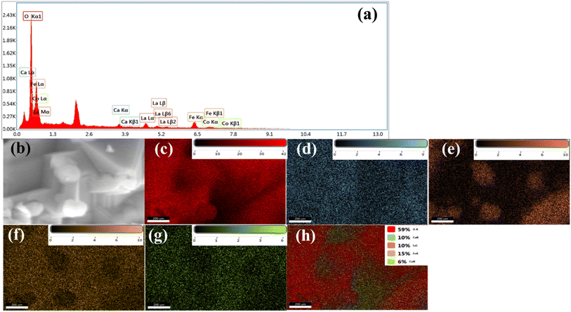 |
| | Fig. 4 (a) EDS spectra, (b) SEM image, (c) elemental mapping images of La, (d) Ca, (e) Co, (f) Fe, and (g) O, and (h) total distribution of LCCFO-0.4 sample. | |
The roughness shown in Fig. 5 and the size distribution shown in Fig. 6 of 100 readings of each sample were measured by Gwadyyin software. This software is used to convert the SEM into AFM images. Roughness and size distribution were investigated in Fig. 3a, d and g in all the samples. The obtained values of root mean square roughness (RMS) are 6.6 nm, 9.17 nm, and 10.05 nm for LCFO, LCCFO-0.1, and LCCFO-0.4, respectively. The increases in the values of RMS roughness are noted with Ca2+ content. This supports the integration of the prepared samples, and Ca ions have been trapped successfully inside the LCFO lattice and show matching with the optical, magnetic, and water contact properties. The increase in roughness increased the surface area.
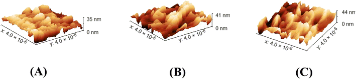 |
| | Fig. 5 Gwyddion images as AFM images of (A) LCFO, (B) LCCFO-0.1, and (C) LCCFO-0.4. | |
 |
| | Fig. 6 Size distribution (A) LCFO, (B) LCCFO-0.1, and (C) LCCFO-0.4. | |
3.3. Contact angle
The geometrical layout and chemical makeup of solid surfaces determine wettability, which is a crucial feature. Studying the basic connection between various nanostructures and hydrophobic behaviour is required to determine the hydrophobic qualities of nanostructured surfaces. The Wenzel model and the Cassie–Baxter model are two theoretical models that serve as the fundamental framework for studying hydrophobic surfaces. For a liquid drop on a solid surface, the contact angle is determined by the surface-free energy involved.| | |
cosθ = (γsv − γsl)/γlv
| (5) |
where the (solid/vapor), (solid/liquid), and (liquid/vapor) tensions are denoted by the letters, γsv, γsl, and, γlv respectively.34 We may explore the geometrical influence on the wetting behaviour of all the created samples because they have distinct hierarchical morphologies. The sessile drop technique is used to assess the static water contact angle (WCA). The contact angle pictures of the various samples are displayed in Fig. 7a–c. For LCFO, LCCFO-0.1, and LCCFO-0.4, the measured values are 112°, 101.2°, and 65°, respectively. Different doped samples were found to have varying levels of hydrophobicity, which is related to surface roughness variation. The contact angle decreased by the air interfaces or grooves between the various components, which is the sole cause of this decrease in wettability. It is well known that a surface's wettability can be determined by combining its surface roughness and surface free energy.34 Due to the high surface polarity that makes water rapidly fill the grooves through capillary action, such roughness is insufficient to generate an enhanced hydrophobic surface. We may explore the geometrical influence on the wetting behaviour of all the created samples because they have distinct hierarchical morphologies.
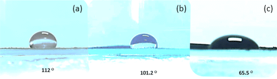 |
| | Fig. 7 The surface wettability of (a) LCFO, (b) LCCFO-0.1, and (c) LCCFO-0.4. | |
3.4. Surface area measurements
Fig. 8 illustrates the prepared samples adsorption and desorption curves by using N2. The curves are close to type IV shapes. There were many spaces between the aggregates of LCFO particles; capillary condensation caused a significant amount of N2 to be absorbed under saturation pressure of saturation. Furthermore, the hysteresis loop of the three samples' hysteresis loop is close to H3-type, as defined by the IUPAC classification of the different hysteresis loops. The created mesopores are situated between the non-rigid plates and have a diameter of up to around 23 nm. Those mesopores were found in the solid state under liquid nitrogen temperature as intraparticle pores that existed among the agglomerating particles. LCFO, LCCFO-0.1, and LCCFO-0.4 samples had BET surface areas of 2.30, 2.38, and 2.65 m2 g−1, respectively. The low surface area was a direct reason for the high temperature, as the preparation method of the work depends on the solid-state reaction method. Table 2 shows the average values of the pore width distribution. The decrease in pore width was interpreted owing the filling of pores with dopant ions or with other particles caused by defects during the preparation process. The total pore volume decreased with Ca2+ ion doping.
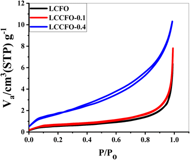 |
| | Fig. 8 N2 adsorption–desorption isotherms of all prepared samples. | |
Table 2 The various surface measurements by BET surface area for the LCFO and the Ca2+ doped samples LCCFO-0.1 and LCCFO-0.4
| Material |
Average pore width (nm) |
Total pore volume (cm3 g−1) |
Surface area (m2 g−1) |
| LCFO |
22.83 |
0.0447 |
2.30 |
| LCCFO-0.1 |
21.95 |
0.0114 |
2.38 |
| LCFO-0.4 |
9.94 |
0.0058 |
2.65 |
3.5. Optical properties
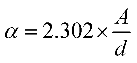
The absorbance curves of LCFO, LCCFO-0.1, and LCCFO-0.4 were carried out from 400 to 1000 nm, showing similar absorbance curves (of double absorption peaks) with slight variation in the absorbance intensity (Fig. 9A). The absorbance data were introduced in the equation to estimate the energy gap (Eg) of the various prepared samples, which showed slight shifting in the recorded peaks with Ca2+ addition. This slight decrease in the direct band gap values confirms the inherent optical properties of LCFO. The values are comparable with various reported publications from the side of the band gap range. For instance, the doping of LaFeO3 with Ca2+ decreased the band gap from 2.02 to 1.11 eV for different ratios.35 The doping of LaFeO3 with different values of Co showed a decreasing band gap of 2.47 to 2.37 eV.36 The absorption coefficient and direct band gap (Tauc equation) were calculated using the next equations, respectively, as eqn (6) and (7).37| |
 | (6) |
| | |
αhυ = B(hυ − Eg)n, Tauc equation
| (7) |
where (α) is the absorption coefficient, the optical absorption (A), material thickness (d), light frequency (ν), Planck constant (h), and independent energy constant (B), and n is the transition value of 0.5 for the direct band gap. In Fig. 9, the direct band gap is shown in Fig. 9B showed a decrease in the values of the band gap values to 1.99, 1.97, and 1.91 eV for LCFO, LCCFO-0.1, and LCCFO-0.4, respectively, and a small, noted straight line is seen around 1.3 eV, enhancing the co-existence of double phase and the presence of two band gap values. The values were 1.32, 1.28, and 1.27 eV for LCFO, LCCFO-0.1, and LCCFO-0.4, respectively. The XRD analysis confirms the two phases' coexistence.
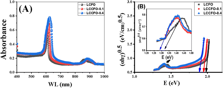 |
| | Fig. 9 UV-Vis (A) absorbance spectrum, (B) direct band gap of all prepared samples. | |
3.6. Electrical properties
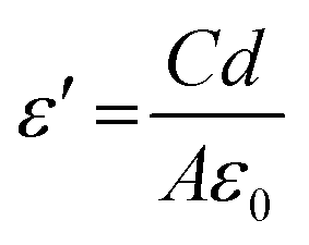
3.6.1. Dielectric property. Dielectric properties were checked in the range of 50 Hz–5 MHz at room temperature. Fig. 10A shows the dielectric constant, dielectric loss, and AC conductivity. The formula used to calculate the dielectric constant is given by eqn (8).| |
 | (8) |
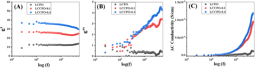 |
| | Fig. 10 Room temperature frequency dependence of (A) dielectric constant, (B) dielectric loss factor (C) AC conductivity of LCFO, LCCFO-0.1, and LCCFO-0.4. | |
The values of C, d, and A represent the capacitance in Farad, the thickness (mm) of the utilised pellet, ε0 the permittivity of the space, and A is the cross-sectional area of the used pellet, respectively. Fig. 10A show the pure sample compared with the other Ca2+ introduced samples. In the beginning, a high value of ε′, as a result of the polarisation process, depends on the applied external field. By increasing the frequency, it cannot follow the applied field, so the polarisation decreases and the dielectric constant decreases because electrons can't continue with the applied field and become saturated (seems to be a constant value), and the change of direction lags behind the applied electric field.38 ε′ values increased two times and three times in the cases of LCCFO-0.1 and LCCFO-0.4 when compared to LCFO at 105 Hz.
3.6.2. Dielectric loss. The real part of the dielectric constant expresses the stored energy while the imaginary part indicated the dissipation of the energy. At low frequencies, dielectric loss values were high; this may be attributed to the dipole oscillation. Also, to admit that the ionic polarisation vanishes at high frequency, no energy is required for the dipole ion's rotation; that's the main reason behind the decrease in dielectric loss values. Of note, the energy dissipation of energy was quite high in LCCFO-0.1 and LCCFO-0.4 if compared to the LCFO sample, as shown in Fig. 10B. At 5 MHz, the value for LCFO is 0.3 for LCFO, increased to 3.44, and then 4.25 for LCCFO-0.1 and LCCFO-0.4, respectively, at 5 MHz. Note that the dielectric constant and loss follow the same behaviour at low frequencies and differ with frequency increasing due to the dissipation factor variance from sample to another. The dielectric loss is calculated from eqn (9).where D is the tan(δ) (tangent of the dielectric loss). The Maxwell–Wagner and Koops model states that conducting grains with a heterogeneous structure are separated by very resistive thin grain boundaries (containing the secondary phase CoFe2O4) in our case as dielectric material.39 As applied field frequency increases, polarisation reduces because there is less electron transfer between Fe3+ and Fe4+ ions and between Co3+ and Co4+ ions, which results in a dielectric constant reduction at a higher frequency regime. Energy losses are significant at low frequencies because of the increased energy required to transfer electrons between Fe3+ and Fe4+ ions and between Co3+ and Co4+ ions owing to grain boundaries. Energy losses are minimal in the high-frequency region because less energy is needed to transport electrons between Fe3+ and Fe4+ ions and between Co3+ and Co4+ ions in the grains.40 At first, the increase in Ca2+ content was followed by a dielectric loss increase. A resonance peak was found in all the prepared samples at 3 MHz. A significant portion of the overall core loss in magnetic materials is due to dielectric loss. For this reason, in certain applications, low dielectric losses are desirable in comparison to low core losses. From our point of view, increasing Ca2+ content forced more Fe3+/Co3+ to be transformed into Fe4+/Co4+ and hopping could occur as follows: (Fe3+/Co3+ into Fe4+/Co4+ + e−).
3.6.3. AC conductivity. Fig. 10C, shows that the AC conductivity is directly proportional to frequency as a result of the disordered dipoles. The trend of all-prepared samples showed a very small increment with the frequency increase at the low frequency range. The calculation of the AC conductivity eqn (10) can be used.ω is the angular frequency (ω = 2 × π × f). The produced samples' hopping motion displays sudden hopping with a translational motion, especially Ca-doped. It was discovered that doping also impacted the findings of the AC conductivity measurement. This can be explained as ferrites' electrical conductivity's frequency dependency according Koop's theory. It states that, at higher frequencies (f > 104 Hz at normal temperature), conductivity shows dispersion, and this dispersion is related to the existence of barriers surrounding highly resistive grains and highly conductivity grains. The increase in conductivity is illustrated by the enhanced charge carrier hopping phenomenon in the high-frequency region exemplifies the increase in conductivity. Electron hopping between Fe3+ and Fe4+ ions, as well as between Co3+ and Co4+ ions has been linked to this conductivity process. The charge carriers are focused on the magnetic ions, and all of the Fe/Co ions in ferrites' octahedral crystal field of ferrites participate in the hopping transport. AC conductivity is directly proportional to the frequency. Nonetheless, the dispersion at high frequencies originated from the conducting grains. AC conductivity rises as the concentration of Ca2+ increases. Since the resistance was increased by increasing polarisation, the AC conductivity is inversely proportional to the dielectric constant.
3.6.4. Magnetic properties. Under an external magnetic field and at room temperature, the different hysteresis loops were evaluated and plotted in Fig. 11. Asymmetric loops were obtained on both sides of the y-axis. Previous reports confirmed the effect of Co ions on increasing the magnetic properties of LaFeO3. For instance, LaCo0.4Fe0.6O3 showed ferromagnetic properties with saturation at 24.4 emu g−1.27 Previous studies41 demonstrated the role of Ca2+ ions in magnetizing the LCFO at various ratios.42 Fe3+ ions tilting towards antiparallel spin in sample La1−xCaxFeO3 are the cause of the increased magnetic moment; this kind of magnetic orientation shift (canting) is brought about by the superexchange interaction of Fe3+ ions via oxygen ions. This is because the sample's antiferromagnetic interactions have gradually decreased, while a weak ferromagnetic component is highly pronounced. As Ca2+ ions substitute La3+ ions on the A-site cation, there will be two possible outcomes: La1−xCaxFeO3, the Ca2+ doping amount (x) causes an increase, which would undoubtedly lead to superexchange interaction as Fe3+ to Fe4+ transition and Co3+ to Co4+ progress. As the doping agent Ca2+ concentration (x) increases, the magnetization shows a rising trend.43 The behaviour is linked to the sample's secondary phase as mentioned in XRD. The second scenario would be an anion deficiency, i.e., lower oxygen stoichiometry to maintain charge neutralisation.
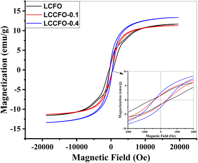 |
| | Fig. 11 M–H Loop of the samples LCFO, LCCFO-0.1, and LCCFO-0.4. | |
In this work, with clear saturation magnetization (Ms) at 11.7 emu g−1 and remanent magnetization (Mr) of 1.6 emu g−1, LCFO exhibited ferromagnetic behavior. The magnetization achieved by inserting a small ratio of Ca2+ showed a very slight decrease in the saturation values and area under the curve. Followed by an obvious increase in the saturation values with increasing the Ca2+ ion values, which detects the effective role of Ca2+ in magnetising the LCFO samples. Table 3 summarizes all estimated values of the prepared samples compared to each other. Note that LaFeO samples are reported to be weak ferromagnetic material, not reaching saturation under an external magnetic field.43 In our case, the enhancement in magnetization is clear. Two-step enhancement occurred in two steps, first by Co doping ferromagnetic material instead of Fe and introducing the Ca2+ ions instead of La3+ ions, which increased the superexchange angle, which in turn strengthened the superexhange interaction leading to magnetization enhancement. Ms reached 1.904 emu g−1, which is reported for LCF co-doped by Co and Ca ions.41 For a deeper point of view about magnetic properties, transition metals have partially filled d orbitals. The d orbitals are divided into two suborbital sets: the t2g (trigonal, lower in energy) and the eg (tetragonal, higher in energy) orbitals.45 The t2g orbitals consist of dxy, dxz, and dyz orbitals, while the eg orbitals consist of dz2 and dx2–y2 orbitals.46 The transition metal ions (Co and Fe) are also coordinated by oxygen ions in an octahedral arrangement. According to Hund's rule, electrons fill the degenerate orbitals of the same energy level with parallel spins before pairing up. In LCFO, the d electrons of both Co and Fe ions preferentially occupy the t2g orbitals because they are lower in energy. The electrons in these t2g orbitals have parallel spins, leading to high magnetic moments associated with the Co and Fe ions due to the strong crystal field splitting.47 Instead of a single element, there is a cooperative effect here from both Co and Fe as partially filled t2g orbitals; they exhibit high magnetic moments.48 These magnetic moments align cooperatively due to exchange interactions between neighbouring ions. The cooperative alignment contributes to the material's overall high magnetic properties of the material. Magneto-crystalline anisotropy, strong crystal field splitting, and the specific orientation of t2g orbitals on the octahedral environment create a preferred direction for magnetic moment alignment of magnetic moments.49 This phenomenon, known as magneto-crystalline anisotropy, further enhanced the coercivity of the nanoparticles.50 The shift observed with the M–H loop here is due to a room temperature exchange bias. This is a direct consequence of the co-existence of two magnetic phases: ferrimagnetic CoFe2O4 on the grain boundary of antiferromagnetic LCFO.
Table 3 The magnetic parameters of the LCFO, LCCFO-0.1 and LCCFO-0.4. Compared to reported samples of LaFeO3
| Sample |
LaFeO3 (ref. 44) |
LCFO |
LCCFO-0.1 |
LCCFO-0.4 |
| Ms negative (emu g−1) |
|
11.60 |
11.29 |
13.38 |
| Ms positive(emu g−1) |
|
11.67 |
11.31 |
13.35 |
| Ms (avg) (emu g−1) |
1.37 × 10⁻³ |
11.63 |
11.30 |
13.36 |
| Mr negative (emu g−1) |
|
1.51 |
1.63 |
2.55 |
| Mr positive (emu g−1) |
|
1.57 |
1.67 |
2.53 |
| Mr (avg) (emu g−1) |
239.35 × 10⁻⁶ |
1.54 |
1.65 |
2.54 |
| Mr/Ms (−ve) |
|
0.130 |
0.135 |
0.190 |
| Mr/Ms (+ve) |
|
0.135 |
0.147 |
0.190 |
| Hci negative (emu g−1) |
|
562.18 |
381.60 |
392.27 |
| Hci positive (emu g−1) |
|
534.79 |
373.50 |
396.70 |
| Hci (avg) (emu g−1) |
173 |
548.49 |
377.55 |
394.49 |
| Area-total (erg g−1) × 103 |
|
18.45 |
12.62 |
15.85 |
| Flatness |
|
0.746 |
0.740 |
0.727 |
3.7. Electrochemical results
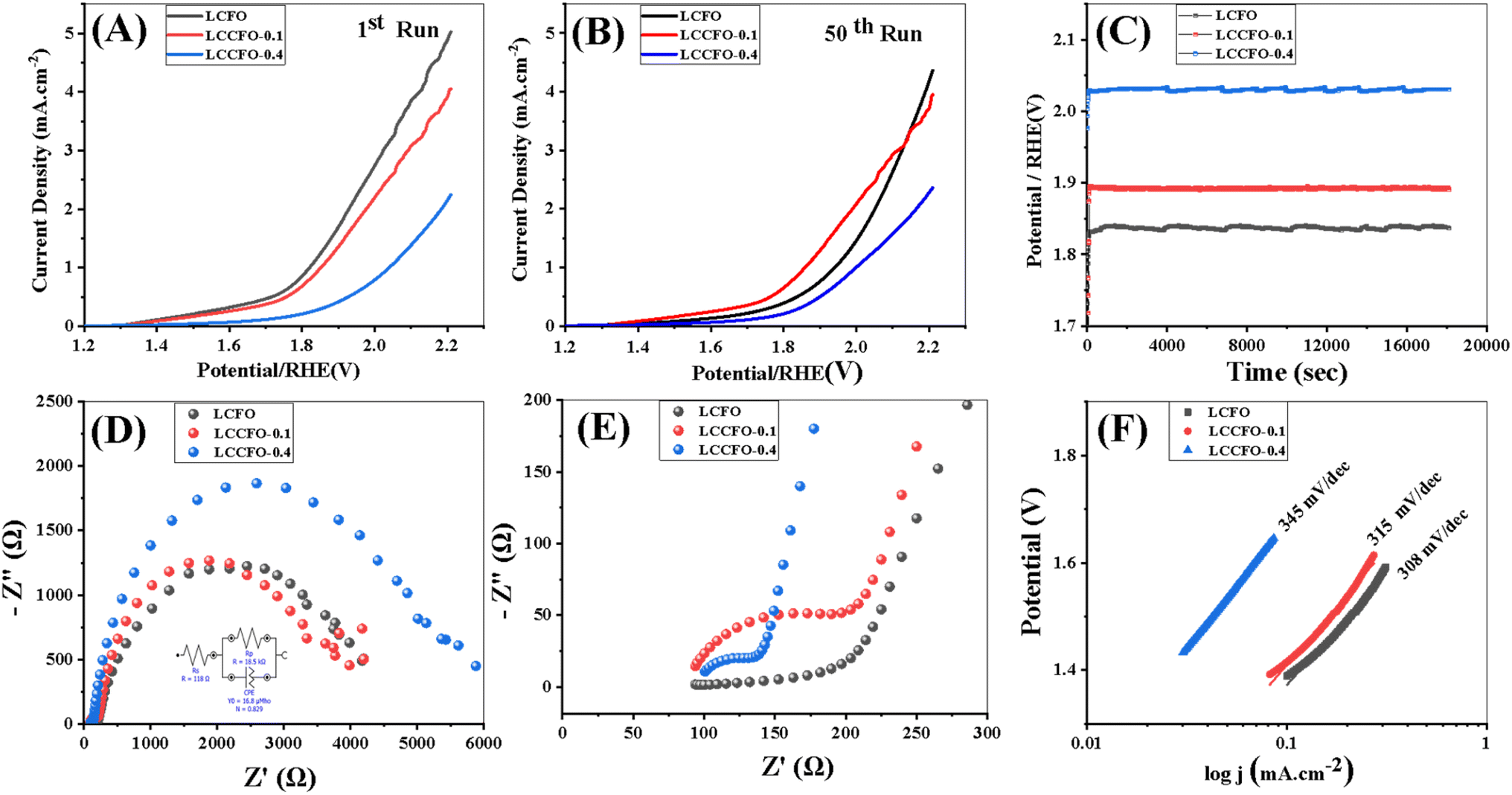
3.7.1. OER performance. The different samples' electrocatalytic performance in a 0.1 M KOH solution was tested using a three-electrode setup with an adjusting scan rate of 5 mV s−1. The 50 runs of LSV curves for LCFO, LCCFO-0.1, and LCCFO-0.4 were plotted as shown in Fig. 12. LCFO showed good catalytic activity higher than LCCFO-0.1 and LCCFO-0.4, which is clear in the current densities of LSV in the 0.1 M KOH solutions. The overpotential was slightly lower in the LCCFO-0.1 and LCCFO-0.4 samples than LCFO as a result of the stability increment, despite the lower current density obtained. This suggests the good role of Ca2+ ions as current stabilisers, but the ratio needs to be further enhanced to keep the current density of the original sample or produce a higher value concerning the stabilised current. Increasing the potential is predicted to increase the current density, as no plateau was obtained in the LSV curves, which means a linear proportional relationship.51 It implies that the current continues to increase linearly with the applied potential. The absence of a plateau may indicate a dynamic or ongoing electrochemical reaction, and not all active species contribute to the reaction. The LSV results are trending with various characterizations. The highest value of current density obtained in LCFO in 0.1 M solutions was 5.14 mA cm−2 and the other maximum current density values were detected to be lower at 4.12 mA cm−2 and 2.45 mA cm−2. Table 4 compares the various types of perovskite equivalent to the work carried out here as OER, ORR, or both to indicate the competitiveness and novelty of the prepared samples. As for the ORR, LCFO recorded the highest values at 3 mA cm−2 and further reduced values for LCCFO-0.1 and 0.4. The commonly known mechanism of perovskite oxide in electrocatalysis in alkaline media depends on the mechanism of adsorbate evolution (AEM),52 where the OH− ions of water molecules are adsorbed into the perovskite active sites (B-sites), causing the formation of several intermediates such as peroxide formation, hydroxide deprotonation, then peroxide deprotonation, and hydroxide reformation. The various intermediate formations, such as OH*, OOH*, and O*, are all common, and electrons are described in the eqn (11)–(14).14| | |
X + OH− → X–OH* + e−
| (11) |
| | |
X–OH* + OH− → X–O* + H2O + e−
| (12) |
| | |
X–O* + OH− → X–OOH* + e−
| (13) |
| | |
X–OOH* + OH− → X + O2 + H2O + e−
| (14) |
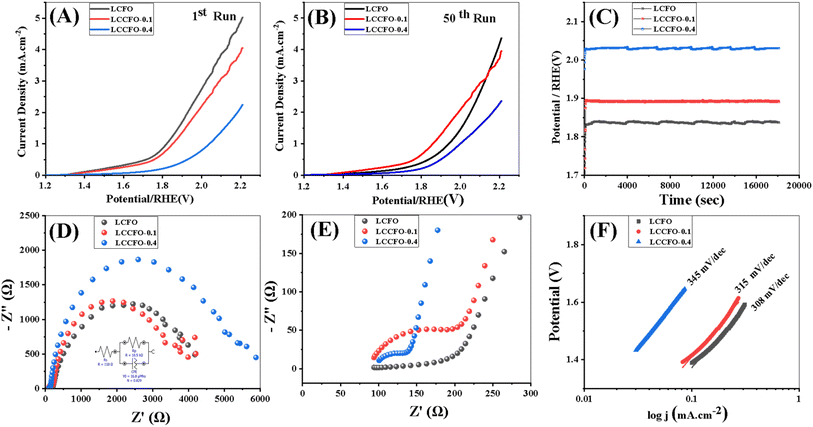 |
| | Fig. 12 (A and B) OER linear sweep voltammetry (LSVs) in 0.1 mol L−1 KOH with a scan rate of 5 mV s−1 for the various samples, (C) chronopotentiometry. (D and E) Nyquist plot. (F) Tafel slope. | |
Table 4 Equivalent circuit parameters including Rs, Rp, and CPE values
| Material |
Rs (Ω) |
Rp (Ω) |
CPE |
| CPE-T |
CPE-P |
| LCFO |
74.5 |
3110 |
9.09 |
0.90 |
| LCCFO-0.1 |
67.5 |
3328 |
16.8 |
0.86 |
| LCCFO-0.4 |
78 |
4550 |
41.7 |
0.78 |
The B-site in perovskite is represented by the X symbol. The EIS of the samples LCFO, LCCFO-0.1, and LCCFO-0.4 was carried out in a 0.1 M KOH solution, as shown in Fig. 12E, with a frequency range of 5 to 100000 Hz. Larger semicircles were measured by Ca2+ addition, confirming the smallest semicircle for LCFO. This indicates improved charge transfer and increased conductivity, where the charge transfer electrons determine the radius of each semicircle.53 The highest catalytic activity sample (LCFO) equivalent circuit was determined by the EIS spectrum analyzer in Fig. 12E, the other circuits showed a greater semi-circle radius, which indicates greater values than the reported ones of the equivalent circuit. Where Rs is the resistance of the ohmic electrolyte measured between the working and reference electrodes, Rp is a pseudo-resistance connected to the mass transfer, adsorption, and desorption limitations of the working electrode.53 The constant phase element (CPE), which is sometimes utilized to display a non-ideal capacitor indicated by depressed semicircle behaviour in the Nyquist plot and may be caused by heterogeneities and surface porosity-was used to improve the theoretical fit of the EIS spectrum.54 For perfect capacitors, the exponent of CPE-T equals 1, and the capacitance value is given as CPE-P in the absence of frequency dispersion.54 The values of the various semi-circles of the different samples are tabulated in Table 4. Chronopotentiometry tests were done to verify that all samples were stable for 18000 s at 1 mA cm−2 vs. RHE in a 0.1 M KOH electrolyte, as shown in Fig. 12D. All samples showed good stability. At higher voltages, the generated current stability was improved by rising Ca2+ ion ratios when compared to the LCFO. The increase in conductivity as a result of Ca2+ content was interpreted and mentioned in Section 3.5.2. Of note, Ca2+ content increased the rate of recombination of the electron–hole pairs generated.55 Table 4 The values of the various parameters related to the equivalent circuit's impedance of LCFO, LCCFO-0.1, and LCCFO-0.4.
Using the Tafel formula (15), the Tafel slopes for OER activities for synthesized catalysts are shown in Fig. 12D. The LCFO measured 308 mV dec−1. This is less than LCCFO-0.1 and LCCFO-0.4 with values 315 mV dec−1 and 345 mV dec−1 respectively.
| | |
η = a + blog(j)
| (15) |
With a and b being constants, the overpotential (η) and current density (j) have a logarithmic relationship. Charge transfer resistance, or RCT, measures the movement of electrons between atoms or compounds during an electrochemical operation.51 It is equivalent to the semicircle's diameter on the Nyquist plot. RCT of the various samples are 105 Ω, 74.5 Ω, and 40 Ω for LCFO, LCCFO-0.1, and LCCFO-0.4 respectively.
3.7.2. ORR electrochemical performance. In a 0.1 M KOH solution, the ORR catalytic activity of the produced electrocatalysts was assessed. Fig. 13A depicts the CV curves of LCFO. The existence of a reduction peak around 0.7 V in the O2 saturated electrolyte but not in the N2 saturated environment verifies the catalyst's ORR catalytic activity.52 A three-electrode electrochemical cell was employed for measuring the electroactive surface area of LCFO, LCCFO-0.1, and LCCFO-0.4. The electrolyte was 0.1 M KOH solution. Therefore, the peak current is proportional to the electroactive surface area of the working electrode and can be expressed by the Randles–Sevcik eqn (16).56| |
 | (16) |
where Ip (A) is the peak current, n is the number of electrons transferred in the redox reaction (n = 1), A (cm2) is the electroactive surface area, D (cm2 s−1) is the diffusion coefficient (the diffusion coefficient of oxygen in 0.1 M KOH at 25 °C is 1.9 × 10⁻⁵ cm2 s−1).57 C (mol cm−3) is the concentration of the reaction species in the electrolyte, and V (V s−1) is the scan rate. The electrochemical surface area (ECSA) = 0.033 cm2 for LCFO, and 0.031 cm2 for both LCCFO-0.1 and LCCFO-0.4.
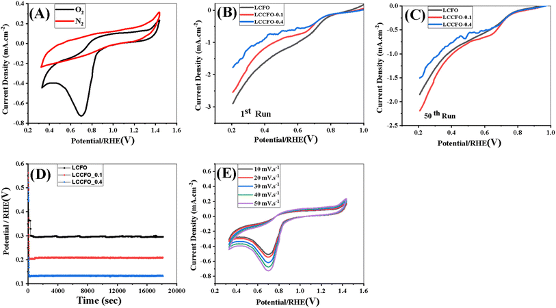 |
| | Fig. 13 (A) Cyclic voltammetry of LCFO in 0.1 M KOH, (B and C) ORR linear sweep voltammetry (LSVs) in 0.1 mol L−1 KOH with a scan rate of 5 mV s−1 for the various samples, (D) chronopotentiometry, (E) cyclic voltammetry of different scan rates of LCFO in 0.1 M KOH. | |
In a 0.1 M KOH solution (O2 saturated medium) and at a scan rate of 5 mV s−1, 50 runs of LSV were assessed to measure the catalytic activity towards ORR, as shown in Fig. 13B and C. The current densities showed a down-and-up trend, which may suggest that, not all the catalytic sites are participating in the reaction simultaneously due to oxygen availability. Also, the variance between the first and 50th runs in the LSV curves of both OER and ORR is due to possible reasons such as the adsorption of contaminants, the development of inactive surface species, or the aggregation of catalyst particles. Certain active sites may eventually lose their activation. There may be a reduction in the quantity of active sites accessible for the catalytic reaction as a result of changes in the covering of active sites by reactants or intermediates over time. As well as the redistribution of active sites over time.58 The maximum current density for LCFO, LCCFO-0.1, and LCCFO-0.4 is 3 mA cm−2, 2.5 mA cm−2, and 1.79 mA cm−2 at onset potential (0.575, 0.525, and 0.566 volts vs. RHE), respectively. The hypothesised ORR reaction mechanism is comparable to the OER reaction mechanism. Because of the extensive dispersion of hydrogen and oxygen on the surface, or H2O, the OH− species are produced when a metal cation is reduced (M+ →M(m−1)+). Overall, O2 that is still being adsorbed onto the oxide surface interacts once more with the generated species (M–OH−).56
| | |
2Mm+–O2− + 2H2O + 2e− → 2M(m−1)+–OH− + 2OH−
| (17) |
| | |
2M(m−1)+–OH− + O2,ads− + e− → 2Mm+–O2− + 2OH−
| (19) |
The electrochemical stability was checked in a 0.1 M KOH solution using chronopotentiometry (Fig. 13D) with a current density fixed at 1 mA cm−2 during the 18000 seconds of the test. According to Fig. 13D, all prepared samples' promising stability increased with Ca2+ doping, with a noticeable decrease in current density values. The stability of LCFO was noticed at a lower applied voltage than the other two samples, which matched the highest current density values.
The presence of two linear zones in linear sweep voltammetry (LSV) curves for ORR due to the Temkin isotherm represents oxygen adsorption on the catalyst surface and is connected to the direct reduction of oxygen to water by four electrons. The Langmuir isotherm's low slope represents oxygen adsorption on the catalyst surface and is connected to the oxygen's two-electron reduction to hydrogen peroxide (H2O2). These two linear zones suggest robust electrocatalytic activity.51,66
Table 5 compares various parameters in OER and ORR of the prepared samples to the recent advances in materials and the noble metals as IrO2 and RuO2 samples. In both OER and ORR, the current density and Eonset are comparable to previous literature samples. The dopant used in this work is of low cost, and this gives it a higher advantage over the various samples from the cost side and a promising area of research.
Table 5 The activity of some perovskite-based electrocatalysts toward OER and ORR A comparison of the bi-functional catalytic activity of LCFO and their doped Ca2+ samples (this work), with the precious metal-based and some other reported excellent perovskite-based functional catalysts in the literature
| Catalysts |
Current density (OER) (mA cm−2) |
Eonset OER (V)/scan rate (mV s−1) |
Current density (ORR) (mA cm−2) |
Eonset ORR (mV)/scan rate (mV s−1) |
Electrolyte |
Ref. Electrode |
Ref. |
| LaFeO3−δ |
10 |
1.74/5 |
1 |
490/5 |
0.1 M KOH |
RHE |
59 |
| La0.98FeO3−δ |
10 |
1.66/5 |
1 |
560/5 |
| La0.95FeO3−δ |
10 |
1.64/5 |
1 |
580/5 |
| La0.90FeO3−δ |
10 |
1.65/5 |
1 |
560/5 |
| La0.9FeO3 |
10 |
1.64/5 |
3 |
380/5 |
0.1 M KOH |
Ag/AgCl |
60 |
| LaFeO3/C |
1 |
0.450/10 |
— |
— |
0.5 M NaOH |
Hg/HgO |
61 |
| LaFeO3/Ni |
10 |
0.350/20 |
— |
— |
1 M KOH |
Hg/HgO |
62 |
| LaFeO3/C |
10 |
0.510/5 |
— |
|
0.1 M KOH |
Ag/AgCl |
57 |
| La0.8Ca0.2FeO3/C |
1 |
0.440/10 |
— |
— |
0.5 M NaOH |
Hg/HgO |
59 |
| La0.6Ca0.4FeO3/C |
|
0.520/10 |
— |
— |
| LaCo0.9Fe0.1O3/C |
1 |
0.390/10 |
— |
— |
1 M KOH |
Calomel |
27 |
| La0.6Ca0.4CoO3/Sb:SnO3 |
10 |
0.470/10 |
— |
— |
RHE |
63 |
| LaNiO3−δ |
|
|
1 |
250/— |
|
Ag/AgCl |
64 |
| LaFe0.5Mn0.5O3 |
10 |
0.454/10 |
7.3 |
200/50 |
0.1 M KOH |
RHE |
65 |
| Pt/C |
10 |
0.219/10 |
1 |
970/10 |
66 |
| IrO2 |
10 |
0.292/— |
— |
— |
0.5 M H2SO4 |
RHE |
67 |
| 1.7/10 |
1 |
380/10 |
0.1 M KOH |
RHE |
57 |
| RuO2 |
10 |
1.64/10 |
1 |
540/10 |
0.1 M KOH |
RHE |
| LaCo0.2Fe0.8O3 |
5.14 |
1.70/5 |
3 |
575/5 |
0.1 M KOH |
RHE |
This work |
| La0.9Ca0.1Co0.2Fe0.8O3 |
4.12 |
1.75/5 |
2.5 |
525/5 |
| La0.6Ca0.4Co0.2Fe0.8O3 |
2.45 |
1.81/5 |
1.77 |
566/5 |
4. Conclusions
The characterization of the various prepared samples showed the successful preparation of the targeted compound. The band gap of the samples confirmed the presence of two phases with two absorbance bands and two band gaps. The 1st decreased from 1.99 to 1.91 eV, and the 2nd was around 1.3 eV. The dielectric behavior followed the Maxwell–Wagner and Koops models, confirming the presence of two types of grains (conducting and resistive). As for the magnetization, it increased in the case of Co doping compared to the reported LaFeO3 (anti-ferromagnetic behavior, with no saturation), then increased with Ca2+ content increment. The confirmation of few Ca2+ ions working as current stabilizers is of high importance and should be tested with different samples to generalize the principle. LCCFO-0.1 showed current densities of 4.12 mA cm−2 and 2.15 mA cm−2 which are comparable to LCFO samples, which showed the highest values of 5.14 mA cm−2 and 3 mA cm−2 for both OER and ORR, respectively. The sample LCCFO-0.1 is highly recommended in the cases of OER and ORR due to the stability of the current density compared to LCFO. The sample LCCFO-0.4 is recommended for magnetic applications as it showed high magnetic properties with a low-cost Ca2+ source (eggshell CaCO3).
Data availability
Data are available upon request from the authors.
Conflicts of interest
There are no conflicts to declare.
Acknowledgements
All authors declare that there are no acknowledgments to be made.
References
- J. Tang, X. Xu, T. Tang, Y. Zhong and Z. Shao, Perovskite-based electrocatalysts for cost-effective ultrahigh-current-density water splitting in anion exchange membrane electrolyzer cell, Small Methods, 2022, 6(11), 2201099, DOI:10.1002/smtd.202201099.
- X. Xu, Y. Pan, Y. Zhong, R. Ran and Z. Shao, Ruddlesden–Popper perovskites in electrocatalysis, Mater. Horiz., 2020, 7(10), 2519–2565, 10.1039/D0MH00477D.
- I. Saad, S. I. El-Dek, M. F. Eissa, L. Assaud, M. R. Abukhadra, W. Al Zoubi, J. H. Kang and R. M. Amin, Recent hydrogen production strategies: Recent advances in electrocatalysis, Inorg. Chem. Commun., 2024, 8, 112474, DOI:10.1016/j.inoche.2024.112474.
- F. Abdelghafar, X. Xu, D. Guan, Z. Lin, Z. Hu, M. Ni and Z. Shao, New Nanocomposites Derived from Cation-Nonstoichiometric Ba x (Co, Fe, Zr, Y) O3− δ as Efficient Electrocatalysts for Water Oxidation in Alkaline Solution, ACS Mater. Lett., 2024, 6, 2985–2994, DOI:10.1021/acsmaterialslett.4c00789.
- S. E. Hosseini and M. Wahid, Hydrogen production from renewable and sustainable energy resources: Promising green energy carrier for clean development, Renewable Sustainable Energy Rev., 2016, 57, 850–866, DOI:10.1016/j.rser.2015.12.112.
- M. Yu, K. Wang and H. Vredenburg, Insights into low-carbon hydrogen production methods: Green, blue and aqua hydrogen, Int. J. Hydrogen Energy, 2022, 46(41), 21261–21273, DOI:10.1016/j.ijhydene.2021.04.016.
- S. V. Venkatesan, A. Nandy, K. Karan, S. R. Larter and V. Thangadurai, Recent advances in the unconventional design of electrochemical energy storage and conversion devices, Electrochem. Energy Rev., 2022, 5, 16, DOI:10.1007/s41918-022-00162-6.
- X. Liu, K. Reddi, A. Elgowainy, H. Lohse-Busch, M. Wang and N. Rustagi, Comparison of well-to-wheels energy use and emissions of a hydrogen fuel cell electric vehicle relative to a conventional gasoline-powered internal combustion engine vehicle, Int. J. Hydrogen Energy, 2020, 45, 972–983, DOI:10.1016/j.ijhydene.2019.10.192.
- M. Amin, H. H. Shah, A. G. Fareed, W. U. Khan, E. Chung, A. Zia, Z. U. R. Farooqi and C. Lee, Hydrogen production through renewable and non-renewable energy processes and their impact on climate change, Int. J. Hydrogen Energy, 2022, 47, 33112–33134, DOI:10.1016/j.ijhydene.2022.07.172.
- L. Elbaz, M. Shao, J. Shui and C. Santoro, Introduction to the themed issue on frontiers of hydrogen energy and fuel cells, Ind. Chem. Mater., 2023, 1, 280–281, 10.1039/D3IM90010J.
- X. Lin, J. J. Foo and W. J. J. Ong, Unveiling environmental impacts of methanol production via electrocatalysis against conventional and thermochemical routes by life cycle assessment, Sustain. Mater. Technol., 2023, 37, e00663, DOI:10.1016/j.susmat.2023.e00663.
- P. Cavaliere, Electrocatalysts for Water Splitting, Water Electrolysis for Hydrogen Production, Springer. 2023, pp. 383–426. DOI:10.1007/978-3-031-37780-8.
- Z.-G. Yang, H. Xu, T.-Y. Shuai, Z. Qi-Ni, Z. Zhi-Jie, K. Huang, C. Dai and G. R. Li, Recent progress in the synthesis of transition metal nitride catalysts and their applications in electrocatalysis, Nanoscale, 2023, 15, 11777–11800, 10.1039/D3NR01607B.
- N. Han, W. Zhang, W. Guo, H. Pan, B. Jiang, L. Xing, H. Tian, G. Wang, X. Zhang and J. Fransaer, Designing oxide catalysts for oxygen electrocatalysis: insights from mechanism to application, Nano-Micro Lett., 2023, 15, 185, DOI:10.1007/s40820-023-01152-z.
- Y. Gu, Z. Yang, J. Zhou and Z. Chen, Technologies, Application of graphene/LDH in energy storage and conversion, Sustainable Mater. Technol., 2023, e00695, DOI:10.1016/j.susmat.2023.e00695.
- R. Kalusulingam, M. Selvam, T. Mikhailova, Y. Popov, S. Khubezhov, I. Pankov and T. N. Myasoedova, Synthesis of CuMoS micro-rods material as efficient bifunctional electrocatalyst for overall water splitting, ChemistrySelect, 2023, 8, e202301649, DOI:10.1002/slct.202301649.
- S. E. Wolf, F. E. Winterhalder, V. Vibhu, L. B. de Haart, O. Guillon, R.-A. Eichel and N. H. Menzler, Solid oxide electrolysis cells–current material development and industrial application, J. Mater. Chem. A, 2023, 11, 17977–18028, 10.1039/D3TA02161K.
- K. Sun, Z. Li, Y. Cao, F. Wang, M. A. Qyyum and N. Han, Recent advancements in perovskite electrocatalysts for clean energy-related applications: Hydrogen production, oxygen electrocatalysis, and nitrogen reduction, Int. J. Hydrogen Energy, 2023, 52, 1004–1126, DOI:10.1016/j.ijhydene.2023.07.009.
- Y. Liu, H. Huang, L. Xue, J. Sun, X. Wang, P. Xiong and J. Zhu, Recent advances in the heteroatom doping of perovskite oxides for efficient electrocatalytic reactions, Nanoscale, 2021, 13, 19840–19856, 10.1039/D1NR05797A.
- Y. Bu, H. Jang, O. Gwon, S. H. Kim, S. H. Joo, G. Nam, S. Kim, Y. Qin, Q. Zhong and S. K. Kwak, Synergistic interaction of perovskite oxides and N-doped graphene in versatile electrocatalyst, J. Mater. Chem. A, 2019, 7, 2048–2054, 10.1039/C8TA09919G.
- H. Liu, J. Guan, S. Yang, Y. Yu, R. Shao, Z. Zhang, M. Dou, F. Wang and Q. Xu, Metal–organic-framework-derived Co2P nanoparticle/multi-doped porous carbon as a trifunctional electrocatalyst, Adv. Mater., 2020, 32, 2003649, DOI:10.1002/adma.202003649.
- R. B. Wexler, G. S. Gautam, E. B. Stechel and E. A. Carter, Factors governing oxygen vacancy formation in oxide perovskites, J. Am. Chem. Soc., 2021, 143, 13212–13227, DOI:10.1021/jacs.1c05570.
- H. Chen, X. Liang, Y. Liu, X. Ai, T. Asefa and X. Zou, Active site engineering in porous electrocatalysts, Adv. Mater., 2020, 32, 2002435, DOI:10.1002/adma.202002435.
- C. E. Beall, E. Fabbri and T. J. Schmidt, Perovskite oxide based electrodes for the oxygen reduction and evolution reactions: the underlying mechanism, ACS Catal., 2021, 11, 3094–3114, DOI:10.1021/acscatal.0c04473.
- S. Najmaei, J. Yuan, J. Zhang, P. Ajayan and J. Lou, Synthesis and defect investigation of two-dimensional molybdenum disulfide atomic layers, Acc. Chem. Res., 2015, 48, 31–40, DOI:10.1021/ar500291.
- A. Ashok, A. Kumar, R. R. Bhosale, F. Almomani, S. S. Malik, S. Suslov and F. Tarlochan, Combustion synthesis of bifunctional LaMO3 (M= Cr, Mn, Fe, Co, Ni) perovskites for oxygen reduction and oxygen evolution reaction in alkaline media, J. Electroanal. Chem., 2018, 809, 22–30, DOI:10.1016/j.jelechem.2017.12.043.
- P. Kamkum, N. Atiwongsangthong, R. Muanghlua and N. Vittayakorn, Application of chicken eggshell waste as a starting material for synthesizing calcium niobate (Ca4Nb2O9) powder, Ceram. Int., 2015, 41, S69–S75, DOI:10.1016/j.ceramint.2015.03.189.
- B. Yan, J. Yue, B. Fan, X. Huang, J. Yang, Z. Du and Y. Liu, Constructing La-doped CoFe2O4/CNTs hybrids with urchin structure for enhanced microwave absorption performance, J. Mater. Res., 2023, 38, 2908–2918 CrossRef CAS.
- A. M. Ibrahim, M. S. Abdel-wahab, M. Elfayoumi and W. Z. Tawfik, Highly efficient sputtered Ni-doped Cu2O photoelectrodes for solar hydrogen generation from water-splitting, Int. J. Hydrogen Energy, 2023, 48, 1863–1876, DOI:10.1016/j.ijhydene.2022.10.089.
- Z. Cheng, Y. Cui, H. Yang and Y. Chen, Effect of lanthanum ions on magnetic properties of Y 3 Fe 5 O 12 nanoparticles, J. Nanopart. Res., 2009, 11, 1185–1192, DOI:10.1007/s11051-008-9501-1.
- R. Kayestha and K. Hajela, ESR studies on the effect of ionic radii on displacement of Mn2+ bound to a soluble β-galactoside binding hepatic lectin, FEBS Lett., 1995, 368, 285–288, DOI:10.1016/0014-5793(95)00673-W.
- Q. Lin, J. Xu, F. Yang, X. Yang, Y. He and F. Materials, The influence of Ca substitution on LaFeO3 nanoparticles in terms of structural and magnetic properties, J. Appl. Biomater. Funct. Mater., 2018, 16, 17–25, DOI:10.1177/2280800017753948.
- J. Sidor, P. Chakravarty, J. Bátorfi, P. Nagy, Q. Xie and J. Gubicza, Assessment of Dislocation Density by Various Techniques in Cold Rolled 1050 Aluminum Alloy, Metals, 2021, 11, 1571, DOI:10.3390/met11101571.
- M. Naeem, H. He, S. Harjo, T. Kawasaki, F. Zhang, B. Wang, S. Lan, Z. Wu, Y. Wu and Z. Lu, Extremely high dislocation density and deformation pathway of CrMnFeCoNi high entropy alloy at ultralow temperature, Scr. Mater., 2020, 188, 21–25, DOI:10.1016/j.scriptamat.2020.07.004.
- M. Shaban, M. Zayed and H. Hamdy, Nanostructured ZnO thin films for self-cleaning applications, RSC Adv., 2017, 7, 617–631, 10.1039/C6RA24788A.
- S. Janaki and K. Punithamurthy, The influence of Ca substitution on LaFeO3 nanoparticles in terms of structural, optical and catalytic properties, Chem. Data Collect., 2021, 34, 100738, DOI:10.1016/j.cdc.2021.100738.
- S. Subudhi, A. Mahapatra, M. Mandal, S. Das, K. Sa, I. Alam, B. Subramanyam, J. Raiguru and P. Mahanandia, Effect of Co doping in tuning the band gap of LaFeO3, Integr. Ferroelectr., 2020, 205, 61–65, DOI:10.1080/10584587.2019.1674998.
- S. El-Dek and W. M. El Rouby, Aerosol Spray Assisted Synthesis of Ni Doped BaTiO3 Hollow Porous Spheres/Graphene as Photoanode for Water Splitting, J. Electrochem. Soc., 2021, 168, 050540, DOI:10.1149/1945-7111/ac001e.
- R. Gao, X. Qin, Q. Zhang, Z. Xu, Z. Wang, C. Fu, G. Chen, X. Deng and W. Cai, Enhancement of magnetoelectric properties of (1-x) Mn0. 5Zn0. 5Fe2O4-xBa0. 85Sr0. 15Ti0. 9Hf0. 1O3 composite ceramics, J. Alloys Compd., 2019, 795, 501–512, DOI:10.1016/j.jallcom.2019.05.013.
- C. J. Anjeline, D. Mali and N. Lakshminarasimhan, High dielectric constant of NiFe2O4–LaFeO3 nanocomposite: Interfacial conduction and dielectric loss, Ceram. Int., 2021, 47, 34278–34288, DOI:10.1016/j.ceramint.2021.08.338.
- M. Ahmed, S. El-Dek and E. B, Extraordinary role of Ca2+ ions on the magnetization of LaFeO3 orthoferrite, Mater. Sci. Eng., B, 2006, 128, 30–33, DOI:10.1016/j.mseb.2005.11.013.
- M. Idrees, M. Nadeem, M. Atif, M. Siddique, M. Mehmood and M. M. Hassan, Origin of colossal dielectric response in LaFeO3, Acta Mater., 2011, 59, 1338–1345, DOI:10.1016/j.actamat.2010.10.066.
- M. Ahmed, R. Seoudi and S. El-Dek, Spectroscopic and structural analysis of Ca substituted La orthoferrite, J. Mol. Struct., 2005, 754, 41–44, DOI:10.1016/j.molstruc.2005.06.027.
- J. Mohapatra, M. Xing, J. Elkins, J. Beatty and J. P. Liu, Size-dependent magnetic hardening in CoFe2O4 nanoparticles: effects of surface spin canting, J. Phys. D: Appl. Phys., 2020, 53, 504004, DOI:10.1088/1361-6463/abb622.
- A. Mahapatra, A. Mitra, A. Mallick, A. Shaw, J.-M. Greneche and P. Chakrabarti, Compounds, Modulation of magnetic and dielectric property of LaFeO3 by simultaneous doping with Ca2+ and Co2+-ions, J. Alloys Compd., 2018, 743, 274–282, DOI:10.1016/j.jallcom.2018.01.207.
- H. Singh, Structural and Spectroscopic Studies of Transition Metal Based Multiferroics and Oxides, Homi Bhabha National Institute, 2015 Search PubMed.
- A. K. Dubey, A. Mukhopadhyay and B. Basu, Interdisciplinary Engineering Sciences: Concepts and Applications to Materials Science, CRC Press, 2020, DOI:10.1201/9780429319631.
- S. Mukhopadhyay, M. Finnis and N. Harrison, Electronic structures and phonon free energies of LaCoO 3 using hybrid-exchange density functional theory, Phys. Rev. B: Condens. Matter Mater. Phys., 2013, 87, 125132, DOI:10.1103/PhysRevB.87.125132.
- G. L. Stamokostas and G. A. Fiete, Mixing of t 2 g− e g orbitals in 4 d and 5 d transition metal oxides, Phys. Rev. B: Condens. Matter Mater. Phys., 2018, 97, 085150, DOI:10.1103/PhysRevB.97.085150.
- J. H. Kim, K. W. Jeong, D. G. Oh, H. J. Shin, J. M. Hong, J. S. Kim, J. Y. Moon, N. Lee and Y. J. Choi, Behavior of magnetoelectric hysteresis and role of rare earth ions in multiferroicity in double perovskite Yb2CoMnO6, Sci. Rep., 2021, 11, 23786, DOI:10.1038/s41598-021-03330-8.
- N. Sivakumar, J. Gajendiran, A. Alsalme and K. Tashiro, Structural, morphological, optical, magnetic and electrochemical behavior of solid state synthesized pure and Sr-doped LaFeO3 nanoparticles, Phys. B, 2022, 641, 414086, DOI:10.1016/j.physb.2022.414086.
- H. K. El Emam, A. Abdelwahab, S. El-Dek and W. M. El Rouby, Performance of Ni-doped BaTiO3 hollow porous spheres supported reduced graphene oxide as an efficient bifunctional electrocatalyst for oxygen evolution reaction and oxygen reduction reaction, Appl. Surf. Sci., 2023, 618, 156599, DOI:10.1016/j.apsusc.2023.156599.
- Y. Zhu, C. Su, X. Xu, W. Zhou, R. Ran and Z. Shao, A universal and facile way for the development of superior bifunctional electrocatalysts for oxygen reduction and evolution reactions utilizing the synergistic effect, Chem.–Eur. J., 2014, 20, 15533–15542, DOI:10.1002/chem.201403192.
- S. Bera, S. Ghosh, T. Maiyalagan and R. N. Basu, Band edge engineering of BiOX/CuFe2O4 heterostructures for efficient water splitting, ACS Appl. Energy Mater., 2022, 5, 3821–3833, DOI:10.1021/acsaem.2c00296.
- R. Doyle and M. Lyons, Kinetics and mechanistic aspects of the oxygen evolution reaction at hydrous iron oxide films in base, J. Electrochem. Soc., 2013, 160, H142, DOI:10.1149/2.015303jes.
- M. Sundararajan, B. Bonisha, M. Ubaidullah, S. M. F. Shaikh, S. Revathi, D. Thiripurasundari, A. T. Dhiwahar, B. Pandit, C. S. Dash and M. Shahazad, Mater. Res. Bull., 2022, 154, 111911, DOI:10.1016/j.materresbull.2022.111911.
- P. Zhu and Y. Zhao, Cyclic voltammetry measurements of electroactive surface area of porous nickel: Peak current and peak charge methods and diffusion layer effect, Mater. Chem. Phys., 2019, 233, 60–67, DOI:10.1016/j.matchemphys.2019.05.034.
- M. Sundararajan, B. Bonisha, M. Ubaidullah, S. M. F. Shaikh, S. Revathi, D. Thiripurasundari, A. T. Dhiwahar, B. Pandit, C. S. Dash and M. Shahazad, Enhanced visible light photocatalytic degradation of rhodamine B using Ni1-xCaxFe2O4 (0≤ x≤ 0.5) nanoparticles: Performance, kinetics and mechanism, Mater. Res. Bull., 2022, 154, 111911, DOI:10.1016/j.materresbull.2022.111911.
- X. Ge, A. Sumboja, D. Wuu, T. An, B. Li, F. T. Goh, T. A. Hor, Y. Zong and Z. Liu, Oxygen reduction in alkaline media: from mechanisms to recent advances of catalysts, ACS Catal., 2015, 5, 4643–4667, DOI:10.1021/acscatal.5b00524.
- Y. Zhu, W. Zhou, J. Yu, Y. Chen, M. Liu and Z. Shao, Enhancing electrocatalytic activity of perovskite oxides by tuning cation deficiency
for oxygen reduction and evolution reactions, Chem. Mater., 2016, 28, 1691–1697, DOI:10.1021/acs.chemmater.5b04457.
- Y. Zhu, W. Zhou, J. Sunarso, Y. Zhong and Z. Shao, Phosphorus-doped perovskite oxide as highly efficient water oxidation electrocatalyst in alkaline solution, Adv. Funct. Mater., 2016, 26, 5862–5872, DOI:10.1002/adfm.201601902.
- R. Sankannavar and A. Sarkar, The electrocatalysis of oxygen evolution reaction on La1− xCaxFeO3− δ perovskites in alkaline solution, Int. J. Hydrogen Energy, 2018, 43, 4682–4690 CrossRef CAS.
- M. Lebid and M. Omari, Engineering, Synthesis and electrochemical properties of LaFeO3 oxides prepared via sol–gel method, Arab. J. Sci. Eng., 2014, 39, 147–152, DOI:10.1007/s13369-013-0883-8.
- N. Fujiwara, T. Nagai, T. Ioroi, H. Arai and Z. Ogumi, Bifunctional electrocatalysts of lanthanum-based perovskite oxide with Sb-doped SnO2 for oxygen reduction and evolution reactions, J. Power Sources, 2020, 451, 227736, DOI:10.1016/j.jpowsour.2020.227736.
- W. Zhou and J. Sunarso, Enhancing Bi-functional electrocatalytic activity of perovskite by temperature shock: a case study of LaNiO3− δ, J. Phys. Chem. Lett., 2013, 4, 2982–2988, DOI:10.1021/jz401169n.
- Q. Dang, H. Lin, Z. Fan, L. Ma, Q. Shao, Y. Ji, F. Zheng, S. Geng, S.-Z. Yang and N. Kong, Iridium metallene oxide for acidic oxygen evolution catalysis, Nat. Commun., 2021, 12, 6007, DOI:10.1038/s41467-021-26336-2.
- J. Zhang, S. Zhu, Y. Min and Q. Xu, Mn-doped perovskite-type oxide LaFeO 3 as highly active and durable bifunctional electrocatalysts for oxygen electrode reactions, Front. Mater. Sci., 2020, 14, 459–468, DOI:10.1007/s11706-020-0513-9.
|
| This journal is © The Royal Society of Chemistry 2024 |

 Open Access Article
 This Open Access Article is licensed under a Creative Commons Attribution-Non Commercial 3.0 Unported Licence
 *a,
S. I. El-Dek
*a,
S. I. El-Dek