 Open Access Article
Effects of the temperature, strain rate, and loading conditions on the deformation behaviors and mechanical properties of the Ni/Ni3Al superalloy†
Xinmao Qin abcd,
Wanjun Yan
 b,
Yilong Liang*acd and
Fei Liacd
aCollege of Materials and Metallurgy, Guizhou University, Guiyang 550025, China. E-mail: ylliang@gzu.edu.cn
bSchool of Electronic and Information Engineering, Anshun University, Anshun 561000, China
cGuizhou Key Laboratory for Mechanical Behavior and Microstructure of Materials, Guiyang 550025, China
dNational & Local Joint Engineering Laboratory for High-performance Metal Structure Material and Advanced Manufacturing Technology, Guiyang 550025, China
First published on 9th July 2024
Abstract
Using the molecular dynamics method, we comprehensively studied the effects of temperature, strain rate, and loading conditions on the deformation behaviors and the mechanical properties of the Ni/Ni3Al superalloy. Our investigation revealed that, an increase of the deformation temperature led to a significant improvement of plastic deformation capacity of the system, but the tensile strength and elastic modulus decreased. And the tensile strength and plastic deformation capacity of the system drastically increased with the strain rate. At high deformation temperature and strain rate, the loading conditions had a large effect on the deformation behaviors and the mechanical properties of the system. The difference of the mechanical properties of the system was mainly due to the different deformation mechanism of the system under different deformation temperature, strain rate and loading conditions. Our study offered a theoretical framework for explaining the difference of the mechanical properties for the Ni/Ni3Al superalloy at different service conditions.
1. Introduction
The Ni/Ni3Al superalloy is a type of aging strengthened alloy widely used for high-temperature applications, and contains a large number of coherent precipitates such as the ordered γ′(Ni3Al) phase. The presence of the γ′(Ni3Al) phase significantly enhances the strength of the alloy at room and elevated temperature. Compared to pure Ni or single-phase materials, the Ni/Ni3Al superalloy exhibits superior strength due to the coherent γ/γ′ phase interface, which impedes dislocation slip under various service environments.1,2 Owing to its excellent properties, such as corrosion resistance and high strength, this superalloy is commonly employed in critical components like oil slinger drum shafts and turbine disk connection bolts in aircraft engines, as well as wind power connection bolts and key components in marine engineering.3–5Numerous studies have been undertaken to examine the deformation and fracture behaviors of the Ni/Ni3Al superalloy.6 Utilizing the spray casting technology, Li et al.7 produced Ni3Al-based superalloys with significant γ/γ′ lattice mismatch and subsequently investigated their mechanical properties. They concluded that the γ/γ′ phase interface plays a crucial role in determining the hardness and elastic modulus. Jena et al.8 studied the evolution of geometrically necessary dislocation (GND) at the γ/γ′ phase interface and its effect on tensile deformation behavior of the disk superalloy. They discovered that the GND value peaks for tensile test specimens at 800 °C, while it is lowest for those tested at 350 °C, which is attributed to the γ/γ′ misfit (δ) value at different test temperatures. Zhang et al.9 demonstrated the superior fatigue fracture resistance of the γ/γ′ superalloy, which mainly attributed to the γ/γ′ phase interface's strongest ability to hinder dislocation slipping. Xia et al.10 found that the interaction between γ/γ′ phase interface and the dislocation (such as Orowan bypassing and dislocation cutting γ′ phase) leads to the significant hardening of the single crystal Ni-based superalloys.
Despite the fabrication of various superalloys with diverse γ and γ′ phase distributions, and the experimental exploration of their mechanical properties at elevated temperatures have been conducted, the underlying mechanism behind the exceptional mechanical properties induced by the γ/γ′ phase interface in superalloys remains elusive. Consequently, there is a pressing need to investigate the deformation and fracture mechanism of γ/γ′ superalloy at atomic-scale. During the deformation process, the atomic-scale molecular dynamics (MD) simulation can record the atomic motion trajectory of the system in real time, and further analyze the microstructure evolution through corresponding visualization software, thus providing a new feasible method for the study of deformation and fracture of materials. To data, MD methods have been widely used to study the deformation and fracture processes of pure metals including FCC metals,11–14 BCC metal,15 and HCP metals.16,17 In addition to pure metals, the deformation and fracture behaviors of binary Ni/Ni3Al superalloy are often investigated using MD method. Yashiroa18 et al. studied the dislocation behavior of the edge of the rectangular precipitate (Ni3Al) in the Ni matrix. They report an behavior of dislocation pinning at γ′ phase, bowing-out in the γ channel. The stability mechanisms of mismatch dislocation networks at different γ(Ni)/γ′(Ni3Al) phase interfaces of Ni-based superalloys were further investigated.1,19–21 Li22 and Chen23 et al. discussed the deformation behaviors and microstructure evolution of γ/γ′ system under shock loading. Kohler24 et al. performed MD simulation of the interaction between edge dislocation of the Ni matrix phase and spherical precipitate, and they found that the interaction type between dislocation and precipitate is related to the size of precipitate. Cui25 et al. explored the effect of microscopic defects on the interaction between dislocation and Ni3Al precipitate, they presented that the nano-scale void led to the Shockley partial dislocations swimmingly enter into the precipitate γ'along the periphery of voids and then glide smoothly, thereby diminishing mechanical properties.
Despite advancements in the field, a critical discussion remains unaddressed concerning the deformation behaviors and corresponding mechanical properties of the Ni/Ni3Al superalloy under various service conditions such as loading condition, deformation temperature, and strain rate. This paper employs the MD method to systematically study the effect of temperature, strain rate, and loading condition on the deformation behaviors and mechanical properties of the Ni/Ni3Al superalloy. And the tensile strength, elastic modulus, and plastic deformation capacity of the systems are calculated during deformation process. The microscopic mechanism of deformation is elucidated through the evolution of microstructure and strain transfer within the system. Our research offers micro-mechanism of deformation of γ/γ′ superalloy under different complex service environments, and provides a theoretical framework to understand the variations in mechanical properties of the Ni/Ni3Al superalloy at different service conditions.
2. Simulation method and details
2.1 Simulation method and model
In this study, the Large-scale Atomic/Molecular Massively Parallel Simulator (LAMMPS)26 software is employed to investigate the deformation and fracture behaviors of the γ(Ni)/γ′(Ni3Al) alloy. The simulation model comprises the γ phase (Ni) and γ′ phase (Ni3Al). The dimensions of the study model are 51.4, 25.7, and 25.7 nm for the X ([100]), Y ([010]), and Z ([001]) axis, respectively. To eliminate the mismatch stress caused by the lattice mismatch of γ phase and γ′ phase, the dimensions of two phases of the simulation model are chosen as (n + 1)aγ ≈ naγ' (n = 72). The lattice constant (aγ and aγ') of γ phase and γ′ phase are 3.524 and 3.573 Å, respectively. And the phase interface between the γ phase and γ′ phase is (100) plane, as shows in Fig. 1.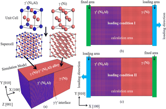 | ||
| Fig. 1 The MD simulation tensile model, (a) the structure of the γ(Ni)/γ′(Ni3Al) alloy, (b) the loading condition I, (c) the loading condition II. | ||
Before tensile deformation, the three-dimensional periodic boundary conditions are applied in the simulation model. Using an isothermal–isobaric ensemble (NPT), the deformation system relaxes for 50 ps at a specific temperature (300, 600, and 900 K) and a pressure of 0 bar. Subsequently, the X-direction of the system is change to the non-periodic and shrink-wrapped boundary conditions, while the Y- and Z-direction still remain with periodic boundary conditions. Then, uniaxial tensile loading is performed along the X-direction using the canonical ensemble (NVT). The deformation system consisted of fixed area, calculation area, and loading area, with thicknesses of 20, 470, and 20 Å, respectively. By change the position of the fixed area and loading area in the deformation system, the loading process is divided into two loading conditions: loading condition I and loading condition II (hereinafter referred to as LC-I and LC-II). For the LC-I, as shows in Fig. 1(b), the fixed area and loading area are located at the left boundary of the γ′ phase side and the right boundary of the γ phase side, respectively. These atoms at the far left are fixed as a fixed area, and a specific rate of movement is applied to the loading area along the positive X-direction. For the LC-II, as shows in Fig. 1(c), the fixed area and loading area are located at the right boundary of the γ phase side and the left boundary of the γ′ phase side, respectively. These atoms at the far right are fixed as a fixed area, and a displacement with a specific rate is applied to the loading area along the negative X-direction. To study the effect of temperature on the deformation behavior, the loading temperatures are set to 300, 600, and 900 K, respectively. And the strain rate of the deformation are 0.0001/ps, 0.001/ps, and 0.01/ps, respectively. It should be noted that in order to verify the repeatability of the calculation results, by changing the random number parameter of each calculation system, we implemented three calculations for each model, respectively. These results show that the calculation data obtained by the same model under different random number parameters are fundamentally consistent, indicating that our calculation results are reliable.
2.2 The atomic interactions potential
The Ni–Ni and Ni–Al atomic interactions are described by eam/fs27 and eam/alloy potential,28 respectively, which was extensively used to simulate mechanical properties of Ni/Ni3Al superalloy. And these results shows that these potentials can be described successfully the relationship between the microstructure evolution and mechanical properties of Ni-based superalloy.23,29,30 Both the eam/fs and eam/alloy potential consist of the terms:
 | (1) |
2.3 Microstructure and strain transfer analysis method
To investigate the deformation and fracture behaviors of these systems, we analyzed the microstructure evolution using polyhedral template matching (PTM)31 and the dislocation extraction algorithm (DXA) from OVITO (The Open Visualization Tool) software.32,33 Additionally, we calculated the atomic-level deformation gradient and strain tensor for each particle based on the relative motion of its neighbors using the atomic strain modifier.34,35 This calculation allows us to explicitly analyze the atomic strain transfer behavior, which further determines the deformation mechanism under various service conditions.3. Results and analysis
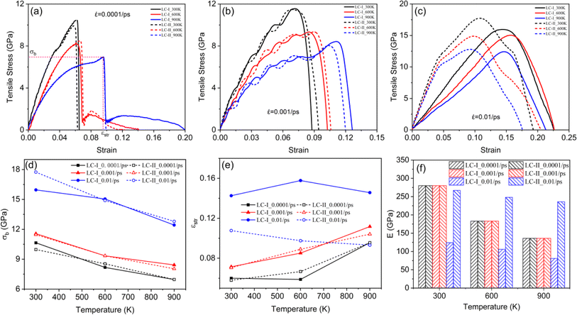
3.1 Stress–strain behaviors
![[small epsi, Greek, dot above]](https://www.rsc.org/images/entities/i_char_e0a1.gif) = 0.0001/ps, and
= 0.0001/ps, and ![[small epsi, Greek, dot above]](https://www.rsc.org/images/entities/i_char_e0a1.gif) = 0.001/ps), an increase in deformation temperature led to a noticeable decrease in both the tensile strength (σb) and the elastic modulus (E) of the system, thereby enhancing the plastic deformation capacity of the deformation system.
= 0.001/ps), an increase in deformation temperature led to a noticeable decrease in both the tensile strength (σb) and the elastic modulus (E) of the system, thereby enhancing the plastic deformation capacity of the deformation system.
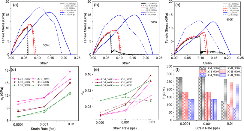
At ![[small epsi, Greek, dot above]](https://www.rsc.org/images/entities/i_char_e0a1.gif) = 0.0001/ps (Fig. 2(a)), during deformation, the tensile stress almost increased monotonically to its maximum with the tensile strain, and then the tensile stress rapidly dropped to about 0 GPa. The deformation system completely fractured after the tensile stress reached its maximum value (σb), and the deformation process of the system mainly occurred at the stage before damage. For different loading conditions, the beginning stages of the stress–strain curve of tensile process almost coincide, indicates that the loading condition does not affect the elastic modulus (E) of the tensile system. For different deformation temperature, the stress–strain curve, tensile strength (σb) and plastic deformation capacity (εstr) of the system under different loading conditions were almost same, which means that the loading condition had no effect on the deformation and fracture behaviors of the Ni/Ni3Al superalloy system at low strain rate (
= 0.0001/ps (Fig. 2(a)), during deformation, the tensile stress almost increased monotonically to its maximum with the tensile strain, and then the tensile stress rapidly dropped to about 0 GPa. The deformation system completely fractured after the tensile stress reached its maximum value (σb), and the deformation process of the system mainly occurred at the stage before damage. For different loading conditions, the beginning stages of the stress–strain curve of tensile process almost coincide, indicates that the loading condition does not affect the elastic modulus (E) of the tensile system. For different deformation temperature, the stress–strain curve, tensile strength (σb) and plastic deformation capacity (εstr) of the system under different loading conditions were almost same, which means that the loading condition had no effect on the deformation and fracture behaviors of the Ni/Ni3Al superalloy system at low strain rate (![[small epsi, Greek, dot above]](https://www.rsc.org/images/entities/i_char_e0a1.gif) = 0.0001/ps). At
= 0.0001/ps). At ![[small epsi, Greek, dot above]](https://www.rsc.org/images/entities/i_char_e0a1.gif) = 0.001/ps (Fig. 2(b)), with the tensile strain increased, the tensile stress of the tensile system increased to its first peak value, then decreased to first valley value, and rapidly decreased to 0 GPa after the tensile stress increased in a wave-pattern to the maximum value. The stress–strain curve indicated that the tensile system exhibited multiple yielding behavior, which means that a large amount of plastic deformation presented at the tensile process. We also found that the tensile strength (σb) and plastic deformation capacity (εstr) were almost unaffected by the loading condition. At
= 0.001/ps (Fig. 2(b)), with the tensile strain increased, the tensile stress of the tensile system increased to its first peak value, then decreased to first valley value, and rapidly decreased to 0 GPa after the tensile stress increased in a wave-pattern to the maximum value. The stress–strain curve indicated that the tensile system exhibited multiple yielding behavior, which means that a large amount of plastic deformation presented at the tensile process. We also found that the tensile strength (σb) and plastic deformation capacity (εstr) were almost unaffected by the loading condition. At ![[small epsi, Greek, dot above]](https://www.rsc.org/images/entities/i_char_e0a1.gif) = 0.01/ps (Fig. 2(c)), as the temperature increased, both the tensile strength (σb) and plastic deformation capacity (εstr) of the tensile system were deteriorated.
= 0.01/ps (Fig. 2(c)), as the temperature increased, both the tensile strength (σb) and plastic deformation capacity (εstr) of the tensile system were deteriorated.
With the deformation temperature increased, regardless of the loading condition and strain rate, the tensile strength (σb) of the tensile system was decreased. At low strain rates, the plastic deformation capacity (εstr) of the system increased with temperature, particularly at 600 and 900 K, indicating improved plasticity of the deformation system. Besides, the elastic modulus (E) of the system decreased with the temperature increased. The difference in loading conditions had little effect on the plastic deformation capacity (εstr) and elastic modulus (E) of the deformation system. Interestingly, for high strain rate, the plastic deformation capacity (εstr) and elastic modulus (E) of the system were mainly affected by the loading condition rather than the deformation temperature. The plastic deformation capacity (εstr) of the system under LC-I was significantly higher than that under LC-II. However, the elastic modulus (E) of the system under LC-I was drastically lower than that under LC-II. Under the same loading conditions and strain rate, the deformation temperature had no effect on the deformation behavior of the tensile system.
3.2 Microstructure evolution and atomic strain transfer analysis
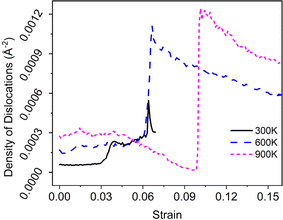
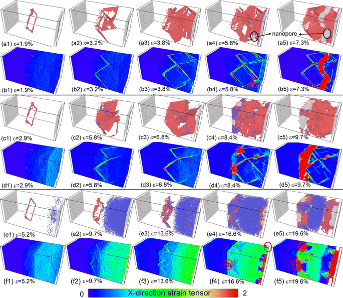
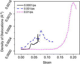
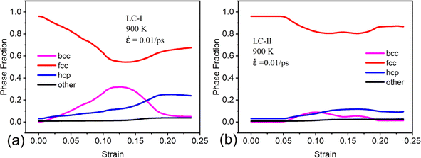
And we can find that the density of dislocations of the whole system was increased with the deformation temperature at the initial deformation stage (Fig. 5). From the Fig. 4(c4) and (e3), the obvious phase transformation from face-centered cubic (fcc) to body-centered cubic (bcc) structure was observed during deformation, and the volume fraction of phase transformation increased significantly with the deformation temperature increased (Fig. 6(a)–(c)). The phase transformation from fcc to bcc structure further led to the atomic strain notably localized at the phase transformation area, resulting in nanopore formation and eventual system fracture (Fig. 4(f3)–(f3) and (e5)). At the low deformation temperature, the deformation behavior of the γ/γ′ superalloy system was mainly the slip of the Shockley partial dislocation. However, in addition to dislocation slip, the phase transformation from fcc to bcc structure also plays an important role in the deformation behavior at the high deformation temperature. Consequently, the tensile strength and elastic modulus of the deformation system decreased with increasing temperature, while plastic deformation capacity improved.
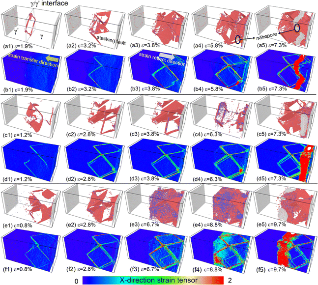
![[small epsi, Greek, dot above]](https://www.rsc.org/images/entities/i_char_e0a1.gif) = 0.0001/ps, the deformation is primarily facilitated by Shockley partial dislocations slip within the γ phase. The atomic strain only localized at the slip plane of these dislocations, especially at the intersection of the two slip planes (the red ellipse in Fig. 7). As the degree of atomic strain localization at these intersections escalates, the nanopore formed at this area and propagated gradually. As the strain rate increased, compared to the Fig. 7(b2), (d2) and (g2), there is a notable decrease in the atomic strain transfer rate. For example, the required total tensile strain of the atomic strain transferred from the right boundary of the γ phase to the γ/γ′ phase interface for the strain rate of 0.0001/ps, 0.001/ps, and 0.01/ps are 3.2%, 5.2%, and 9.7%, respectively. Consequently, under the high strain rate, the atomic strain gradient in the deformation system is formed in the strain transfer direction of the γ phase, instead of only localized on the slip plane of the Shockley partial dislocation. This deformation behavior resulted in the tensile strength, elastic modulus and plastic deformation capacity of the γ/γ′ superalloy increased significantly with the strain rate increased. Compared to the Fig. 8 and 9, it can be seen that the main deformation mechanism of the system was dislocation slip at low strain rate (0.0001/ps and 0.001/ps), but the phase transformation from the fcc structure to bcc was the primary deformation mechanism under high strain rate (0.01/ps).
= 0.0001/ps, the deformation is primarily facilitated by Shockley partial dislocations slip within the γ phase. The atomic strain only localized at the slip plane of these dislocations, especially at the intersection of the two slip planes (the red ellipse in Fig. 7). As the degree of atomic strain localization at these intersections escalates, the nanopore formed at this area and propagated gradually. As the strain rate increased, compared to the Fig. 7(b2), (d2) and (g2), there is a notable decrease in the atomic strain transfer rate. For example, the required total tensile strain of the atomic strain transferred from the right boundary of the γ phase to the γ/γ′ phase interface for the strain rate of 0.0001/ps, 0.001/ps, and 0.01/ps are 3.2%, 5.2%, and 9.7%, respectively. Consequently, under the high strain rate, the atomic strain gradient in the deformation system is formed in the strain transfer direction of the γ phase, instead of only localized on the slip plane of the Shockley partial dislocation. This deformation behavior resulted in the tensile strength, elastic modulus and plastic deformation capacity of the γ/γ′ superalloy increased significantly with the strain rate increased. Compared to the Fig. 8 and 9, it can be seen that the main deformation mechanism of the system was dislocation slip at low strain rate (0.0001/ps and 0.001/ps), but the phase transformation from the fcc structure to bcc was the primary deformation mechanism under high strain rate (0.01/ps).
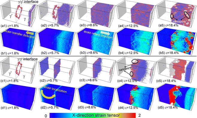
![[small epsi, Greek, dot above]](https://www.rsc.org/images/entities/i_char_e0a1.gif) = 0.01/ps. When the high deformation temperature and strain rate were applied to the deformation system, the deformation behavior was mainly conducted by the phase transformation from the fcc to bcc structure, rather than dislocation slip (Fig. 10(a1)–(a5) and (c1)–(c5)). Under the LC-I, with the tensile strain increased, the atomic strain gradually transferred from the right boundary of the γ phase to the γ/γ′ phase interface. Subsequent to the transfer of atomic strain to the γ/γ′ interface, a reflection of the atomic strain towards the right direction of the system was observed (Fig. 10(b3)). Then the atomic strain localization was observed at the intersection of two dislocation slip plane at the later stages of deformation. This phenomenon led to the formation of nanopores in that specific region.
= 0.01/ps. When the high deformation temperature and strain rate were applied to the deformation system, the deformation behavior was mainly conducted by the phase transformation from the fcc to bcc structure, rather than dislocation slip (Fig. 10(a1)–(a5) and (c1)–(c5)). Under the LC-I, with the tensile strain increased, the atomic strain gradually transferred from the right boundary of the γ phase to the γ/γ′ phase interface. Subsequent to the transfer of atomic strain to the γ/γ′ interface, a reflection of the atomic strain towards the right direction of the system was observed (Fig. 10(b3)). Then the atomic strain localization was observed at the intersection of two dislocation slip plane at the later stages of deformation. This phenomenon led to the formation of nanopores in that specific region.
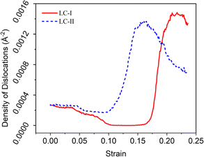
For the LC-II, tensile deformation was induced by moving the left boundary of the γ′ phase to the left. Consequently, in a homogeneous deformation system, the deformation process involved a gradual transfer of atomic strain from the left side of the system to the right side. When ε = 1.8%, the atomic strain only localized at the left boundary of the γ′ phase, and the γ/γ′ interface misfit dislocation network almost maintained unchanged. As ε = 5.7%, however, the atomic strain localization region suddenly shifted from the left side of the system to the γ/γ′ phase interface (the yellow arrow of the Fig. 10(d2)), which led to the phase transformation from fcc to bcc structure in the local region of the γ/γ′ phase interface (Fig. 10(c2)). After that, the atomic strain was difficult to transfer from the γ/γ′ phase boundary to the right side of the γ phase. As a result, the intersection of the two slip planes and the γ/γ′ phase interface experienced significant atomic strain localization due to a combination of partial dislocation slip and phase transformation (the red ellipse in Fig. 10(d3) and (d4)). The pronounced atomic strain localization led to the formation of nanopores in this region (Fig. 10(c4)). The tensile system with LC-II exhibits a distinct atomic strain transfer behavior, resulting in a significantly higher elastic modulus compared to the system under LC-I. However, this system's plastic deformation capacity is notably lower than that of the system under LC-I. From the Fig. 11 and 12, we can further confirmed that the phase transformation was the primary deformation mechanism for high deformation temperature and strain rate.
4. Discussions
With the increase of the deformation temperature, the movement activity of the atoms in the system was enhanced, resulting in the increase of the equilibrium distance of the atoms, which caused the interaction force between the atoms decrease. And the density of dislocations of the whole system was increased with the deformation temperature at the initial deformation stage. Thus, the tensile strength, elastic modulus of the deformation system decreased as the deformation temperature. And the plastic deformation capacity of the system increased, which resulted in the plastic deformation capacity of the system before damage drastically improved.At the low strain rate, the primary deformation behavior of the deformation system was the mutual slip of the Shockley partial dislocation dissociated from the γ/γ′ phase interface dislocation network (Fig. 7(a1)–(a5)). Nevertheless, under the high strain rate, the main deformation mechanism was the phase transformation (fcc → bcc structure), due to the system was difficult to deform through the dislocation slip (Fig. 7(e1)–(e5)). The phase transformation of the deformation system required a lot of external deformation energy, so the deformation system has high tensile strength, elastic modulus, and plastic deformation capacity at the high strain rate. This results indicated that the tensile strength, elastic modulus, and plastic deformation capacity enhanced remarkably with the strain rate increased.
Besides, the effect of the loading condition on the deformation behavior of the system was analyzed as follow. To analyze the effect of loading condition on the strain transfer process and the corresponding deformation behaviors of the system, we first calculated the elastic modulus of the single γ(Ni) and γ′(Ni3Al) phase using the Cambridge Serial Total Energy Package (CASTEP),36 which was based on the density functional theory. And the elastic modulus of the single γ(Ni) and γ′(Ni3Al) phase is 98 and 122 GPa, respectively (as shows in Fig. 13(a)). As a result of the low elastic modulus of the γ(Ni), when the LC-I was applied to the deformation process, the atomic strain first transferred form the right boundary of the γ phase to the γ/γ′ phase interface, and then reflected from the γ/γ′ phase interface towards the γ phase once the atomic strain transfer reached the γ/γ′ phase interface (Fig. 13(b)). The atomic strain transfer and reflection process consumed a large mount of deformation work, so the deformation system with the LC-I has superior plastic deformation capacity before system damage. Under the LC-II, however, the atomic strain first localized at the left boundary of the γ′ phase in the initial stage of the deformation. However, owing to the higher tensile strength and elastic modulus of the γ′ phase compared to the γ phase, it was difficult to uniformly transfer atomic strain within the γ′ phase.37 The atomic strain localization region directly transferred from the left boundary of the γ′ phase to the right side of the γ/γ′ phase interface (Fig. 13(c)). Then, as the tensile deformation continue, the atomic strain almost localized at the nearby region of the right side of the γ/γ′ phase interface (Fig. 13(c)). The atomic strain transfer abruptly from the left boundary of the γ′ phase to the right side of the γ/γ′ phase interface resulted in the lower plastic deformation capacity of the system before damage, and the higher elastic modulus.
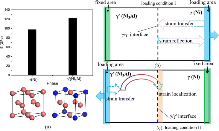 | ||
| Fig. 13 The elastic modulus of the γ(Ni) and γ′(Ni3Al) phase (a), and the strain transfer process of the system under different loading conditions: (b) LC-I, (c) LC-II. | ||
5. Conclusions
Using the molecular dynamics method, we comprehensively study the effects of temperature, strain rate, and loading condition on the deformation behaviors and the mechanical properties of the Ni/Ni3Al superalloy. Our investigation present that, an increase of the deformation temperature led to a significant improvement of plastic deformation capacity of the system, but the tensile strength and elastic modulus decreased. And the tensile strength and plastic deformation capacity of the system drastically increased with the strain rate. At high deformation temperature and strain rate, the loading condition had a large effect on the deformation behaviors and the mechanical properties of the system. For example, compared to the LC-II, the deformation system with LC-I has superior plastic deformation capacity, but the elastic modulus of the system with LC-I lower obviously. And the tensile strength of the system with LC-I slightly greater than the LC-II. The difference of the mechanical properties of the system is mainly due to the different deformation mechanism of the system under different deformation temperature, strain rate and loading conditions. Our study offered a theoretical framework for explaining the difference of the mechanical properties for the Ni/Ni3Al superalloy at different service conditions.Data availability
The data supporting this article have been included as part of the ESI.†Author contributions
Xinmao Qin: writing original manuscript, Wanjun Yan: computational method and analysis, Yilong Liang: review and editing manuscript, Fei Li: visualization.Conflicts of interest
There are no conflicts to declare.Acknowledgements
This work was finally funded by the Engineering Technology Research Center (No. [2019]5303), the central government guides local science and technology development (No. [2019]4011) and the Project of the Education Department of Guizhou Province (No. [2021]315).References
- W.-P. Wu, Y.-F. Guo, Y.-S. Wang, R. Mueller and D. Gross, Molecular dynamics simulation of the structural evolution of misfit dislocation networks at γ/γ′ phase interfaces in Ni-based superalloys, Philos. Mag., 2011, 91(3), 357–372 CrossRef CAS.
- J. Yu, Q. Zhang, R. Liu, Z. Yue, M. Tang and X. Li, Molecular dynamics simulation of crack propagation behaviors at the Ni/Ni3Al grain boundary, RSC Adv., 2014, 4(62), 32749 RSC.
- T. M. Pollock and S. Tin, Nickel-Based Superalloys for Advanced Turbine Engines: Chemistry, Microstructure and Properties, J. Propul. Power, 2006, 22(2), 361–374 CrossRef CAS.
- A. Chamanfar, L. Sarrat, M. Jahazi, M. Asadi, A. Weck and A. K. Koul, Microstructural characteristics of forged and heat treated Inconel-718 disks, Mater. Des., 2013, 52, 791–800 CrossRef CAS.
- D. McAllister, D. Lv, B. Peterson, H. Deutchman, Y. Wang and M. J. Mills, Lower temperature deformation mechanisms in a γ′′-strengthened Ni-base superalloy, Scr. Mater., 2016, 115, 108–112 CrossRef CAS.
- J. Zhou, Y. Yang and Y. Yu, Revealing mechanical property–strengthening micro-mechanism of Ni/Ni3Al-based alloys by molecular dynamics simulation, J. Mol. Model., 2022, 28(11), 371 CrossRef CAS PubMed.
- Y. Li, C. Li, L. Yu, Z. Ma, H. Li and Y. Liu, Characterization of γ′ precipitate and γ/γ′ interface in polycrystalline Ni3Al-based superalloys, Vacuum, 2020, 176, 109310 CrossRef CAS.
- P. S. M. Jena, S. K. Pradhan, S. Tripathy, B. Mahato, C. Fernando, N. Paulose and J. K. Sahu, Evolution of geometrically necessary dislocation at the γ-γ′ interface and its effect on tensile deformation behaviour of disk super alloy, Mater. Sci. Eng. A, 2021, 807, 140855 CrossRef CAS.
- Z. Zhang, Y. Liu, Z. Wang, J. Huang, S. Chen, Z. Ye, X. Chen and J. Yang, Influence behavior and mechanism of γ′- or γ′′-precipitated phase types on damage resistance of heterogeneous interface in nickel-based superalloys, J. Alloys Compd., 2022, 924, 166559 CrossRef CAS.
- W. Xia, X. Zhao, J. Wang, Q. Yue, Y. Cheng, L. Kong, Y. Zhang, Y. Gu, H. Bei and Z. Zhang, New strategy to improve the overall performance of single-crystal superalloys by designing a bimodal γ′ precipitation microstructure, Acta Mater., 2023, 257, 119200 CrossRef CAS.
- X. Qin, Y. Liang, J. Gu and G. Peng, The Effect of Interatomic Potentials on the Nature of Nanohole Propagation in Single-Crystal Nickel: A Molecular Dynamics Simulation Study, Crystals, 2023, 13(4), 585 CrossRef CAS.
- C. B. Cui and H. G. Beom, Molecular dynamics simulations of edge cracks in copper and aluminum single crystals, Mater. Sci. Eng. A, 2014, 609, 102–109 CrossRef CAS.
- X. R. Zhuo, J. H. Kim and H. G. Beom, Atomistic investigation of crack growth resistance in a single-crystal Al-nanoplate, J. Mater. Res., 2016, 31(9), 1185–1192 CrossRef CAS.
- X. F. Liu, J. B. Wang, L. G. Sun, Y. Y. Zhang, M. L. Tian and X. Q. He, Investigation on crack propagation in single crystal Ag with temperature dependence, J. Mater. Res., 2015, 30(22), 3553–3563 CrossRef CAS.
- Z. Wang, X. Shi, X.-S. Yang, W. He, S.-Q. Shi and X. Ma, Atomistic simulation of martensitic transformations induced by deformation of α-Fe single crystal during the mode-I fracture, J. Mater. Sci., 2020, 56(3), 2275–2295 CrossRef.
- T. Tang, S. Kim and M. F. Horstemeyer, Molecular dynamics simulations of void growth and coalescence in single crystal magnesium, Acta Mater., 2010, 58(14), 4742–4759 CrossRef CAS.
- J. Li, L. Dong, X. Zang, X. Zhang, W. Zhao and F. Wang, Study on micro-crack propagation behavior of single-crystal α-Ti under shear stress based on molecular dynamics, Mater. Today Commun., 2020, 25, 101622 CrossRef CAS.
- K. Yashiroa, M. Naitob and Y. Tomitac, Molecular dynamics simulation of dislocation nucleation and motion at γ/γ' interface in Ni-based superalloy, Int. J. Mech. Sci., 2002, 44, 1845–1860 CrossRef.
- T. Zhu and C.-y. Wang, Misfit dislocation networks in the γ/γ′ phase interface of a Ni-based single-crystal superalloy: Molecular dynamics simulations, Phys. Rev. B: Condens. Matter Mater. Phys., 2005, 72(1), 014111 CrossRef.
- N.-L. Li, W.-P. Wu and K. Nie, Molecular dynamics study on the evolution of interfacial dislocation network and mechanical properties of Ni-based single crystal superalloys, Phys. Lett. A, 2018, 382(20), 1361–1367 CrossRef CAS.
- H. Yang, L. Zhu, R. Zhang, J. Zhou and Z. Sun, Influence of high stacking-fault energy on the dissociation mechanisms of misfit dislocations at semi-coherent interfaces, Int. J. Plast., 2020, 126, 102610 CrossRef.
- B. Li, C. Dong, J. Yu, Q. Zhang, H. Zhou and R. Liu, Mechanical behaviour and microstructural evolution of Ni-based single crystal alloys under shock loading, RSC Adv., 2018, 8(39), 22127–22135 RSC.
- B. Chen and W.-P. Wu, Molecular dynamics simulations of dynamics mechanical behavior and interfacial microstructure evolution of Ni-based single crystal superalloys under shock loading, J. Mater. Res. Technol., 2021, 15, 6786–6796 CrossRef CAS.
- C. Kohler, P. Kizler and S. Schmauder, Atomistic simulation of the pinning of edge dislocations in Ni by Ni3Al precipitates, Mater. Sci. Eng. A, 2005, 400–401, 481–484 CrossRef.
- C. Cui, X. Gong, L. Chen, W. Xu and L. Chen, Atomic-scale investigations on dislocation-precipitate interactions influenced by voids in Ni-based superalloys, Int. J. Mech. Sci., 2022, 216, 106945 CrossRef.
- A. P. Thompson, H. M. Aktulga, R. Berger, D. S. Bolintineanu, W. M. Brown, P. S. Crozier, P. J. in 't Veld, A. Kohlmeyer, S. G. Moore, T. D. Nguyen, R. Shan, M. J. Stevens, J. Tranchida, C. Trott and S. J. Plimpton, LAMMPS – a flexible simulation tool for particle-based materials modeling at the atomic, meso, and continuum scales, Comput. Phys. Commun., 2022, 271, 108171 CrossRef CAS.
- G. J. Ackland, G. Tichy, V. Vitek and M. W. Finnis, Simple N-body potentials for the noble metals and nickel, Philos. Mag. A, 1987, 56(6), 735–756 CrossRef CAS.
- G. P. Purja Pun and Y. Mishin, Development of an interatomic potential for the Ni-Al system, Philos. Mag., 2009, 89(34–36), 3245–3267 CrossRef CAS.
- L. Ben, Z. Shiming, F. A. Essa, D. Chao, Y. Jingui and Z. Qiaoxin, Crack Propagation and Microstructural Evolution of Ni-based Single Crystal Alloy Under Shear Loads, Rare Met. Mater. Eng., 2018, 47(5), 1370–1376 CrossRef.
- B. Chen, W.-P. Wu and M.-X. Chen, Orientation-Dependent Morphology and Evolution of Interfacial Dislocation Networks in Ni-Based Single-Crystal Superalloys: A Molecular Dynamics Simulation, Acta Mech. Solida Sin., 2020, 34(1), 79–90 CrossRef.
- P. M. Larsen, S. Schmidt and J. Schiøtz, Robust structural identification via polyhedral template matching, Modell. Simul. Mater. Sci. Eng., 2016, 24(5), 055007 CrossRef.
- A. Stukowski, Visualization and analysis of atomistic simulation data with OVITO–the Open Visualization Tool, Modell. Simul. Mater. Sci. Eng., 2010, 18(1), 015012 CrossRef.
- A. Stukowski, V. V. Bulatov and A. Arsenlis, Automated identification and indexing of dislocations in crystal interfaces, Modell. Simul. Mater. Sci. Eng., 2012, 20(8), 085007 CrossRef.
- F. Shimizu, S. Ogata and J. Li, Theory of Shear Banding in Metallic Glasses and Molecular Dynamics Calculations, Mater. Trans., 2007, 48(11), 2923–2927 CrossRef CAS.
- M. L. Falk and J. S. Langer, Dynamics of viscoplastic deformation in amorphous solids, Phys. Rev. E: Stat. Phys., Plasmas, Fluids, Relat. Interdiscip. Top., 1998, 57(6), 7192–7205 CrossRef CAS.
- S. J. Clark, M. D. Segall, C. J. Pickard, P. J. Hasnip, M. I. J. Probert, K. Refson and M. C. Payne, First principles methods using CASTEP, Z. Kristallogr. Cryst. Mater., 2005, 220(5–6), 567–570 CrossRef CAS.
- L. Ma, S. Xiao, H. Deng and W. Hu, Atomic simulation of fatigue crack propagation in Ni3Al, Appl. Phys. A: Mater. Sci. Process., 2014, 118(4), 1399–1406 CrossRef.
Footnote |
| † Electronic supplementary information (ESI) available. See DOI: https://doi.org/10.1039/d4ra04034a |
| This journal is © The Royal Society of Chemistry 2024 |

