 Open Access Article
Preparation and characterization of palladium nanoparticle-embedded carbon nanofiber membranes via electrospinning and carbonization strategy
Man Gonga,
Xiaomin Li ab,
Lei Hua,
Hang Xua,
Changshu Yanga,
Yuhan Luoa,
Shu Lia,
Chuanqiang Yin
 *ab,
Min Ganc and
Lang Zhouab
aInstitute of Photovoltaics, Nanchang University, Nanchang 330031, PR China. E-mail: cqyin@ncu.edu.cn
bInstitute of New Materials Technology, NCU-GQC Institute of PV-HE-ES Technology, Jiujiang 332020, PR China
cSchool of Physics and Materials Science, Nanchang University, Nanchang 330031, PR China
First published on 8th July 2024
Abstract
Carbon nanofiber membranes (CNMs) are expected to be used in many energy devices to improve the reaction rate. In this paper, CNMs embedded with palladium nanoparticles (Pd-CNMs) were prepared by electrospinning and carbonization using polyimide as the raw material. The effects of carbonization temperature, carbonization atmosphere, and heating rate on the physicochemical properties of the as-obtained Pd-CNMs were studied in detail. On this basis, the electrocatalytic performance of Pd-CNMs prepared under optimal conditions was characterized. The results showed that highly active zero-valent palladium nanoparticles with uniform particle size could be distributed on the surface of carbon nanofibers. Under vacuum conditions, at a carbonization temperature of 800 °C and a heating rate of 2 °C min−1, Pd-CNMs have lower H2O2 yield, lower Tafel slope (73.3 mV dec−1), higher electron transfer number (∼4), and superior durability, suggesting that Pd-CNMs exhibit excellent electrocatalytic activity for ORR in alkaline electrolyte. Therefore, polyimide-derived CNMs embedded with Pd nanoparticles are expected to become an excellent cathode catalyst layer for fuel cells.
1 Introduction
With the increasing demand for energy and the improvement of environmental quality, renewable energy equipment must be developed to solve the serious environmental pollution problems.1,2 In energy conversion devices, in particular, fuel cells and metal–air batteries, the oxygen reduction reaction (ORR) occurs at the cathode and is a crucial reaction for high performance. In order to improve cell potential, it is necessary to efficiently reduce oxygen at the cathode. Platinum (Pt) and Palladium (Pd) materials are considered to be the most optimal catalysts for oxygen reduction reaction (ORR) in terms of catalytic activity. Pt/C and Pd/C catalysts are widely employed in various industrial organic catalysis and electrochemical catalysis applications. This is because of their high catalytic activity and resource cost-performance ratio.3–10 The precious metals need to be in the form of highly dispersed nanoparticles and uniformly loaded on carbon materials with a large specific surface area to improve the utilization rate of active ingredients in the fuel cells. The carbon structure of traditional Pd/C catalysts is mostly in the form of activated carbon, carbon black, artificial graphite, and other particles. However, the traditional Pd/C catalyst has some problems, such as easy caking, easy corrosion loss, rapid attenuation of catalytic activity, serious pulverization pollution, and difficult post-use recycling.11–13 In the last three decades, a lot of scientific research has been carried out in the field of carbon nanomaterials all over the world due to their significant electronic, optical, mechanical, chemical and thermal properties.14 The fibers prepared by electrospinning technology have the characteristics of nano-size effects, high specific surface area, high porosity, etc.15–17 All kinds of inorganic particulate or precious metal catalysts can be effectively dispersed on the fibers, greatly reducing the agglomeration probability of the catalysts and enhancing the catalytic activity. In recent years, many researchers have leveraged the unique characteristics of nano-catalysts to develop an in situ loading method for nanoparticles on fiber surfaces or inner holes. This includes the surface effect, the small-size effect, and the high loading capacity of electrospun fibers. This approach has enabled the preparation of supported catalytic materials with synergistic catalytic effects.18,19 In addition to the application of catalytic membranes for oxygen reduction reaction (ORR) on the cathode of fuel cells,20 they can also be applied as flexible electrode materials in zinc–air batteries.21 Moreover, they are the key catalytic material in realizing green wastewater treatment by bioelectrochemical systems.22 The other applications of catalytic membranes include pollution-free supported photocatalytic materials for treating refractory organic wastewater, electrically assisted membrane bioreactors,23 formaldehyde adsorption in the air, indoor air purification, and protective masks.24 T. H. Vignesh Kumar fabricated semi-conducting single-walled carbon nanotube-based field-effect transistors (s-SWCNT/FETs) decorated with cobalt ferrite (CFO) nanoparticles, which were subsequently utilized to connect the source and drain electrodes, facilitating the electron transport within the device. As-prepared CFO/s-SWCNT/FET had been used for the non-enzymatic detection of carbaryl and carbofuran.25 Dutt S. has developed a binder-free electrode based on a MnO2/rGO nanocomposite, which is intended for direct implementation in supercapacitor systems.26 Vasanth Magesh developed an electrochemical sensor for the determination of ethanol in human salivary samples. The chemical reduction of HAuCl4 using Sparfloxacin (Sp) leads to the formation of gold nanoparticles (Sp-AuNPs). An activated screen-printed carbon electrode (A-SPE) was modified with a dispersion of Sp-AuNPs.27 Aamir Ahmed has reported the sulfonation technique for stabilizing the surgical face masks and their conversion into carbon nanoparticles for application as a supercapacitor electrode. The electrode is fabricated by preparing a slurry paste of carbon nanoparticles and pasting it on a conductive wearable fabric.28The carbon nanofiber membranes (CNMs) serve as a catalyst support material with various advantages, including a large specific surface area, strong bearing capacity, good toughness, and high strength. Polyacrylonitrile (PAN)-derived carbon fiber accounts for as much as 90% of the total carbon fiber output. The PAN-derived carbon fiber is the main variety of carbon fiber precursors. Typically, the manufacturing process of PAN is intricate since it involves many steps, such as precursor preparation, preoxidation, oxidation, carbonization, etc., which must be carefully controlled and optimized.29,30 Compared with PAN, polyimide (PI) exhibits superior carbon yield and enhanced mechanical properties, which have garnered the attention of a diverse group of researchers.31 The inherent molecular structure characteristics of aromatic PI make it possible to omit the complicated preoxidation process when preparing carbon fibers, reducing energy consumption.32–34 Therefore, it is a valuable way to prepare unique free-standing structured PI-derived support materials for precious metal catalysts with good conductivity by electrospinning and carbonization.
In this study, PI-derived CNMs embedded with palladium nanoparticles (Pd-CNMs) were prepared using electrospinning and carbonization. Detailed investigations were conducted to analyze the impact of carbonization temperature, heating rate, and atmosphere on the structure and properties of Pd-CNMs. Electrochemical characterization results were obtained for Pd-CNMs prepared under the optimal conditions. The results showed that Pd-CNMs are expected to become an excellent cathode catalyst for fuel cells.
2 Experimental
2.1 Materials
Pyromellitic dianhydride (PMDA, ≥99.5%), provided by Tianjin Haopu Chemical Co., Ltd, was dried in vacuum at 150 °C for 2 h before use. 4,4′- diaminodiphenyl ether (ODA, ≥99.5%) was obtained from Wanda Chemical Co., Ltd. N,N-dimethylacetamide (DMAc, AR) was purchased from Sinopharm Chemical Reagents Co., Ltd. Palladium acetylacetonate (≥99.0%) was acquired from Beijing Bailingwei Technology Co., Ltd.2.2 Synthesis of Pd(acac)2-PAA solution
PMDA and ODA were utilized as raw materials, and DMAc served as the solvent. Initially, ODA dissolved in DMAc and stirred thoroughly under a nitrogen atmosphere. Under mechanical stirring, PMDA was added repeatedly to attain an ODA-to-PMDA molar ratio of 1![[thin space (1/6-em)]](https://www.rsc.org/images/entities/char_2009.gif) :
:![[thin space (1/6-em)]](https://www.rsc.org/images/entities/char_2009.gif) 1.01. The polyimide precursor (PAA) solution with a solid content of 10 wt% was prepared by stirring polymerization. The combination of palladium acetylacetonate and an appropriate amount of DMAc was prepared, followed by ultrasound-assisted dispersion and subsequent addition to the PAA solution. Finally, the electrospinning PAA solution was prepared by thoroughly stirring for 12 h under a low-temperature nitrogen flow at −10 °C. The rotational viscosity of the solution was measured with a value ranging from 60
1.01. The polyimide precursor (PAA) solution with a solid content of 10 wt% was prepared by stirring polymerization. The combination of palladium acetylacetonate and an appropriate amount of DMAc was prepared, followed by ultrasound-assisted dispersion and subsequent addition to the PAA solution. Finally, the electrospinning PAA solution was prepared by thoroughly stirring for 12 h under a low-temperature nitrogen flow at −10 °C. The rotational viscosity of the solution was measured with a value ranging from 60![[thin space (1/6-em)]](https://www.rsc.org/images/entities/char_2009.gif) 000 to 80
000 to 80![[thin space (1/6-em)]](https://www.rsc.org/images/entities/char_2009.gif) 000 mPa s.
000 mPa s.
2.3 Preparation of Pd(acac)2-PAA nanofiber membrane
The fully stirred Pd(acac)2-PAA precursor solution was put into a 5 mL syringe and electrospun. Parameters were set as follows: the advancing speed was 1 mL h−1, the rotating speed was 140 r min−1, the spinning voltage was 16 kV. To ensure the formation of a carbon film of a certain thickness post-heat treatment, the spinning time was controlled to yield a Pd(acac)2-PAA nanofiber membrane with a thickness of approximately 300 μm. The resultant fiber membrane demonstrated an exceptional degree of softness and exhibited superior mechanical properties.2.4 Preparation of Pd-CNMs
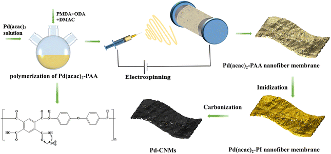
Imidization of Pd(acac)2-PI was achieved by placing Pd(acac)2-PAA in a muffle furnace and heating it from room temperature to 350 °C at a controlled heating rate. The Pd(acac)2-PI nanofiber membranes were laid between the polished artificial graphite sheets to slow down the deformation during heat treatment. Samples were put into a carbide furnace, and the temperature was raised from room temperature to 500 °C at a heating rate of 10 °C min−1 in different atmospheres (vacuum, argon) separately. At different heating rates (2 and 0.5 °C min−1), the temperature was raised from 500 °C to the final carbonization temperature (600, 800, and 1000 °C) and maintained for 30 min before cooling naturally. The schematic illustration for the preparation of Pd-CNMs is shown in Fig. 1. As a reference, the vacuum atmosphere was replaced with Ar/H2 flow (95![[thin space (1/6-em)]](https://www.rsc.org/images/entities/char_2009.gif) :
:![[thin space (1/6-em)]](https://www.rsc.org/images/entities/char_2009.gif) 5) during the cooling process, abbreviated as Vac-Ar/H2.
5) during the cooling process, abbreviated as Vac-Ar/H2.
2.5 Characterization
The crystal structure of Pd-CNMs was characterized by X-ray diffraction (XRD, D8 ADVANCE, Bruker, Germany). Scanning electron microscopy (SEM, Phenopharos, Phenom-World, Netherlands) and transmission electron microscopy (TEM, JEM-2100, Japan Electronics) were employed to analyze the micro-morphology of Pd-CNMs. The valence states of elements on the surface of materials were investigated using X-ray photoelectron spectroscopy (XPS, ESCALAB 250Xi, Thermo Fisher Scientific, MA, USA). The electrochemical performance was tested using an electrochemical workstation (CHI760D, Shanghai Chenhua, China) in a three-electrode system with a glassy carbon electrode as the working electrode, a platinum electrode as the counter electrode, and an Ag/AgCl electrode as the reference electrode.3 Results and discussion
3.1 Effect of carbonization temperature on the as-obtained Pd-CNMs
The Pd-CNMs obtained at carbonization temperatures of 600, 800, and 1000 °C, respectively, labeled as Pd-CNMs-600 °C, Pd-CNMs-800 °C, and Pd-CNMs-1000 °C, were carbonized under argon atmosphere with a heating rate of 2 °C min−1. The surface morphologies of Pd-CNMs at different carbonization temperatures were characterized, as shown in Fig. 2. With the increase in the carbonization temperature, the fiber diameter decreased significantly from 220 to 143 nm. The average diameter of the nano fibers gradually decreases with the increase of temperature. The PI molecular chain shrinks during imidization and carbonization. Element decomposition and solvent volatilization also occur in the heating process, which jointly reduce the diameter of the fibers. The average diameter of Pd-CNMs-600 °C was approximately 220 nm. After the heat treatment at 800 °C, the removal of non-carbon atoms was continued. At this time, the average diameter of the fiber was about 184 nm. Furthermore, after the heat treatment at 1000 °C, the average diameter of the fiber continued to shrink to a diameter of about 143 nm. During the heat treatment process, due to the elevated temperature that intensifies atomic motion, there is a greater propensity for the atoms to aggregate towards the surface with higher energy. As illustrated in Fig. 2(d) and (e), a substantial quantity of Pd nanoparticles accumulated on the surface of carbon nanofibers. It can be seen from the cross-sectional morphology of Pd-CNMs (Fig. 2(f)) that in many smooth cylindrical fibers in Pd-CNMs, a large number of pores were formed by overlapping fibers. This shows that electrospun fibers had the morphological characteristics of a porous structure with a large specific surface area.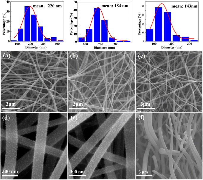 | ||
| Fig. 2 The SEM images of (a) and (d) Pd-CNMs-600 °C, (b) and (e) Pd-CNMs-800 °C, (c) Pd-CNMs-1000 °C, and (f) the cross-sectional SEM image of Pd(acac)2-PAA. | ||
The crystal structure of Pd particles on carbon nanofibers at different carbonization temperatures was discussed. As shown in Fig. 3, the diffraction pattern of samples had several peaks at 2θ of 40.43, 46.46, and 68.51°, corresponding to (111), (200), and (220) facets of Pd (PDF#46-1043), respectively. This implies the formation of a crystalline Pd with a face-centered cubic (FCC) structure. In addition, when the carbonization temperature was 600 °C, a broadening peak appeared in the XRD pattern, corresponding to the Pd (111) crystal plane. This indicates that Pd had a crystalline structure with low crystallinity and small grain size. The Pd particles were reduced and crystallized during the high-temperature treatment. It is widely known that the broadening of the diffraction peak is mainly caused by grain refinement and/or microscopic strain. The influence of microscopic strain is assumed to be neglected during this preparation process. According to the Scherrer formula, the average crystallite size of Pd particles was about 5.50 nm. When the carbonization temperature was 800 °C, the crystallinity of Pd particles increased, and the grain size increased. According to the profile fitting in Fig. 3(b), the XRD diffraction peak of Pd (111) was separated into a broad peak and a sharp peak. The corresponding grain sizes were calculated to be 11.9 and 48.3 nm according to the full width at half maximum (FWHM). After the high-temperature treatment at 1000 °C, only sharp diffraction peaks of the Pd appeared in the XRD pattern. This indicates that more Pd particles (about 40.3 nm) migrated and grew up.
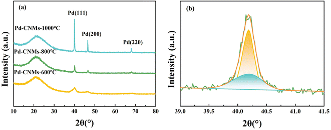 | ||
| Fig. 3 (a) XRD patterns of Pd-CNMs at different temperatures under argon atmosphere; (b) fitting curves of Pd (111) diffraction peak for Pd-CNMs-800 °C. | ||
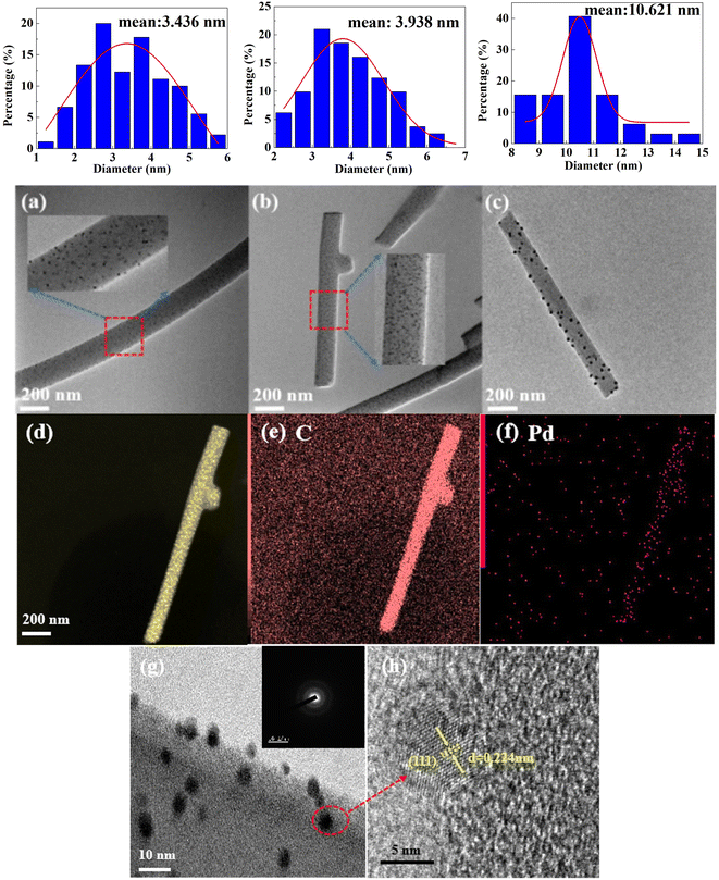
Due to the distribution of Pd nanoparticles both on the surface and inside the carbon nanofiber, the aggregation states of the two were different, varying the particle size. Only the Pd nanoparticles on the surface of the fiber significantly impact catalytic performance. XRD analysis indicates that the particle size distribution of Pd nanoparticles on the surface may exhibit a significant deviation from the actual state. This describes the particle size variation trend with carbonization temperature in general terms. The TEM images of Pd-CNMs were analyzed to further investigate the distribution of Pd nanoparticles on fibers at different carbonization temperatures. Fig. 4(a) displays the TEM image of Pd-CNMs-600 °C, revealing that Pd nanoparticles were evenly dispersed on the carbon fiber surface. The average particle size was 3.44 nm, aligning with the calculated value from XRD. This indicates that the nano-Pd particles within and around the fibers were relatively small and uniform. When the carbonization temperature was 800 °C, more Pd particles migrated to the surface of the carbon fiber under high-temperature thermal traction. At elevated temperatures, Pd nanoparticles coalesced and expanded, increasing the particle size. Simultaneously, some palladium particles were deposited on the surface of carbon nanofiber filaments. Due to the high-temperature evaporation of Pd particles on the surface, the growth rate of these particles was slower than that of the interior. This resulted in the formation of two types of Pd particles with distinct average particle sizes, as shown in the previous XRD results. As shown in Fig. 4(b), the average size of Pd particles on the surface was 3.94 nm. This finding contrasts with the small particle size of 11.9 nm calculated by XRD. This is potentially due to the limited proportion of nanoparticles on the surface and insufficient migration and aggregation of internal nanoparticles, resulting in the coexistence of particles with two distinct sizes. When the carbonization temperature was 1000 °C, the Pd particles continued to migrate and slightly agglomerated on the surface, resulting in a particle size of 10.6 nm. A crucial factor influencing the utilization rate of the catalyst is the distribution of metal particles. This diminishes the electrochemically active surface area and mass-specific activity. Consequently, a smaller particle size correlates with an enhanced electrochemical performance.35
Energy-dispersive X-ray spectroscopy (EDX) was also employed to further probe the elements and their locations on the CNMs. As illustrated in Fig. 2(d–f), the CNMs had a uniform distribution of Pd elements. This well-distributed presence of Pd sites significantly enhanced the ORR performance. Fig. 4(g) displays the outcome of amplification of Pd-CNMs nanofibers. Pd nanoparticles appeared in dark regions due to the higher electron density. Fig. 4(h) shows the high-resolution TEM (HRTEM) image of a single Pd nanoparticle, and the lattice spacing of the (111) crystal plane of FCC Pd was 0.224 nm.
Fig. 5 depicts the XPS spectra of Pd-CNMs at different carbonization temperatures. It can be seen that nitrogen existed in the form of pyridinic-N, pyrrolic-N, and graphitic-N. Pyridinic-N (where N is bonded to two carbon atoms) and graphitic-N (where N is bonded to three carbon atoms) are the active sites to facilitate the 4e− pathway of ORR due to their sp2 hybrid orbital that enhances electronic conductivity.36–38 Fig. 5(d) shows that the contents of pyridinic-N and graphitic-N at different temperatures were almost the same. This suggests that the temperature will not affect the electronic conductivity by changing the nitrogen content.
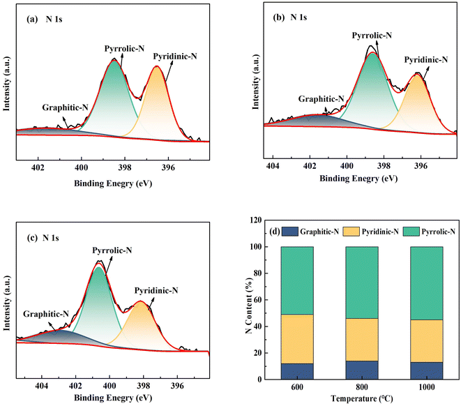 | ||
| Fig. 5 The N1s spectrum for (a) Pd-CNMs-600 °C, (b) Pd-CNMs-800 °C, and (c) Pd-CNMs-1000 °C; (d) ratios of the N content. | ||
Fig. 6 displays the detailed XPS spectrum of Pd3d located on CNMs, revealing two chemical valence states. One state was the Pd metal in a zero-valence state within the Pd3d orbit, with binding energies of 335 and 340 eV. The other state represents the oxidized form of Pd, with binding energies of 337 and 342 eV. The relative atomic percentage in the XPS spectra was determined, as illustrated in Fig. 6(d). The highest content of Pd oxide was 73 at% at 800 °C. This shows that most of Pd was oxidized during carbonization at 800 °C. With the temperature increase, the surface oxidation of Pd became more severe. Due to the migration and agglomeration of Pd particles at 1000 °C, particles became larger and the specific surface area decreased, decreasing the Pd oxidation. Therefore, a higher concentration of divalent Pd was present at 800 °C. Altering the reaction atmosphere and heating rate can increase the proportion of active zero-valent Pd particles and decrease the content of Pd oxide. Based on the above analysis, the optimal carbonization temperature was 800 °C, and further research was carried out on this basis.
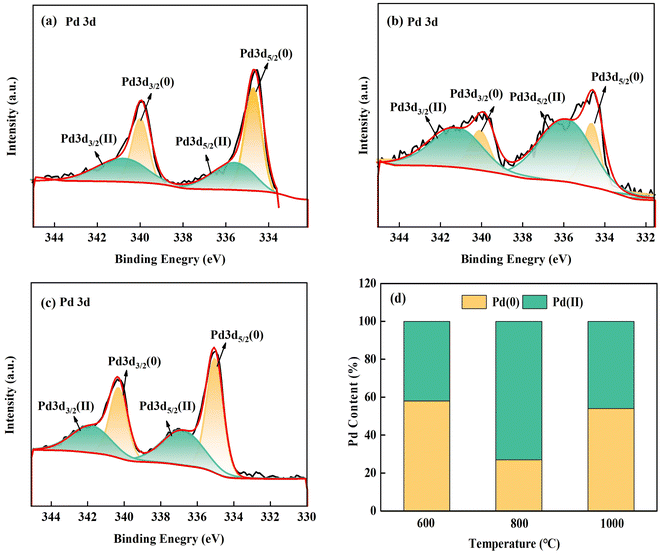 | ||
| Fig. 6 Pd3d spectra for (a) Pd-CNMs-600 °C, (b) Pd-CNMs-800 °C, and (c) Pd-CNMs-1000 °C; (d) ratios of the Pd content. | ||
3.2 Effect of carbonization atmosphere on the as-obtained Pd-CNMs
At 800 °C, Pd particles exhibited a favorable particle size distribution and size. Nonetheless, the surface of the Pd particles on the surface of the fiber possessed a high oxygen content. A reducing atmosphere was introduced during the cooling annealing process to reduce Pd oxide. The carbonization temperature was set at 800 °C, the heating rate was 2 °C min−1, and the reduction of Pd was adjusted by controlling different environmental atmospheres during carbonization and annealing. This aimed to obtain zero-valent Pd nanoparticles with a small particle size and uniform dispersion.As shown in Fig. 7(a), a broadening peak with low intensity appeared in the XRD pattern, corresponding to the Pd (111) crystal plane in a vacuum atmosphere. This indicates that the Pd particles were crystalline with a low crystallinity. Due to the high vacuum atmosphere in the carbonization process, some fine Pd particles that migrated to the fiber surface quickly evaporated.
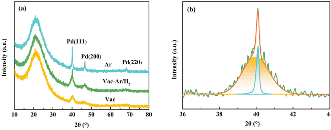 | ||
| Fig. 7 (a) XRD patterns of samples at 800 °C in different atmospheres, (b) fitting curves of Pd (111) diffraction in Vac-Ar/H2. | ||
Moreover, the vacuum condition had a higher vapor pressure, resulting in the generation of smaller palladium particles on the surface of the fiber under the same conditions. According to the Scherrer formula, the average crystallite size of Pd particles was about 5.1 nm. As mentioned, under a high-argon atmosphere, a broad peak and a sharp peak related to the (111) crystal plane appeared, indicating an increase in the crystallinity of Pd particles. The average particle size of Pd particles after increasing crystallinity was about 30.1 nm.
In general, the particle size of Pd particles could be reduced under vacuum conditions. Ar/H2 gas with low reduction protection was introduced in the annealing process to partially reduce divalent Pd to continuously increase the proportion of active zero-valent state and reduce the proportion of oxidized state. The (111) crystal plane also had a sharp peak and broad peak. Both narrow and broad peaks are ascribed to the (111) crystal plane. The sizes of the internal and external palladium particles were 43.7 and 4.70 nm, respectively. This phenomenon is attributed to the pressure variation from vacuum to argon-hydrogen mixed gas during the cooling annealing process, which led to the formation of coarse palladium particles.
As shown in Fig. 8, after high-temperature carbonization in different atmospheres, Pd exhibited two states: zero-valent metallic Pd and oxidized Pd in the Pd3d orbit. The relative atomic percentage of Pd in XPS was calculated by area integration. Its oxidized state accounted for 73% in the argon atmosphere, 55% in the high vacuum atmosphere, and 64% in the annealing atmosphere with reducing protective gas after high vacuum. When a high-purity protective gas is used as a carbonization condition, “toxic gases” such as CO react with Pd to form PdO, resulting in a deactivated oxidation state. Under high vacuum conditions, some “toxic gases” are rapidly extracted without binding with Pd in time, and the proportion of oxidized Pd generated is reduced. After high-vacuum carbonization and annealing in a reducing atmosphere, part of the oxidized Pd is reduced to zero-valence Pd under H2 reduction. However, in the gas conversion process, the trace amount of oxygen entering the furnace from the gas pipeline may be the main factor that increases the oxygen content. Therefore, in this experiment, the combined effect of hydrogen reduction was not obvious.
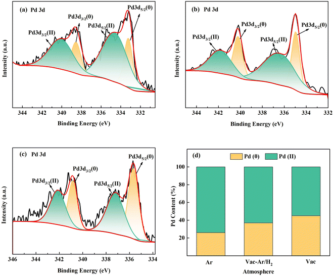 | ||
| Fig. 8 The Pd 3d spectrum of samples at 800 °C under different atmospheres (a) Ar, (b) Vac-Ar/H2, and (c)Vac; (d) ratios of the Pd content. | ||
3.3 Effect of heating rate on the as-obtained Pd-CNMs
The pyrolysis process of PI was explored based on the above study to explore the formation mechanism of divalent Pd and improve the activity of Pd-CNMs. With the temperature increase, PI molecules gradually changed into a crystalline state, and the carbonyl group in the molecular chain broke and deoxygenated at 700 °C. At 800 °C, the residual nitrogen and oxygen were removed to form a polycyclic compound.39 In addition, when heated to 800 °C, Pd will react with CO to form PdO and lose activity.40 It is not clear whether altering the heating rate can affect the release rates of CO and CO2, thus achieving the objective of lowering the PdO content. The subsequent experiments aimed to confirm the relationship between the formation of PdO and the release rate of CO and CO2. The experiment was designed to mitigate the adverse effects of CO on Pd by reducing the carbonization rate within a high vacuum environment. Carbonization was carried out in vacuum, and the temperature was raised to 800 °C at the heating rates of 0.5 and 2 °C min−1. The XPS results mentioned above are illustrated in Fig. 9.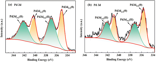 | ||
| Fig. 9 The Pd3d spectrum of samples at 800 °C and different heating rates of (a) 0.5 and (b) 2 °C min−1 in a vacuum atmosphere. | ||
As shown in Fig. 9, the relative atomic percentage in XPS spectra was calculated, and when the heating rate was 0.5 °C min−1, the ratio of oxidized state was 55%. Similarly, when the heating rate was 2 °C min−1, the ratio of oxidized state was 54%. The small difference between these two values indicates that the heating rate had little effect on the surface chemical state of Pd.
3.4 Electrochemical performances of the as-obtained Pd-CNMs
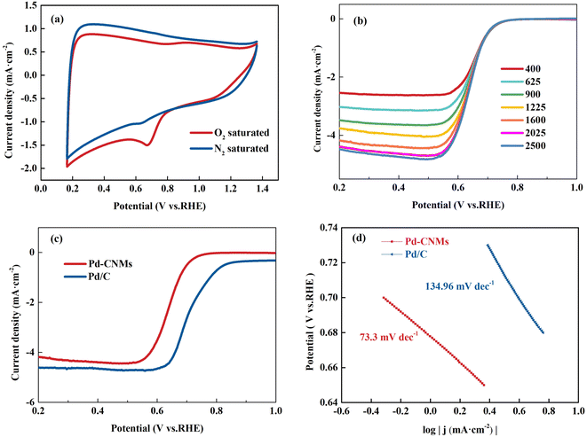
The cyclic voltammetry (CV) and linear sweep voltammetry (LSV) results for Pd-CNMs-800 °C are presented from Fig. 10(a) and (b). The test employs 0.1 M KOH (Ph = 13) as the electrolyte due to its favorable conductivity, which facilitates efficient electron and ion transport, crucial for the progression of electrode reactions. Additionally, controlling the acidity and alkalinity at this concentration allows for the fulfillment of experimental conditions while mitigating risks and costs. Fig. 10 displays the ORR activity analysis of Pd-CNMs using 0.1 M KOH electrolyte, either O2-saturated or N2-saturated, at a scan rate of 10 mV s−1. When the electrolyte was saturated with O2, Pd-CNMs showed a substantial reduction process, and the cathodic peak corresponding to ORR was observed in the range between 0.65 and 0.68 V. This indicates that Pd-CNMs had good oxygen reduction electrocatalytic performance. LSV measurements were performed to understand the electron transfer kinetics of Pd-CNMs-800 °C at different rotation speeds ranging from 400 to 2500 rpm using a rotating disk electrode (RDE), as shown in Fig. 10(b). It can be seen that the limiting current density increased with increasing the rotating rate. The limiting current density curves of Pd-CNMs and commercial Pd/C were recorded at 1600 rpm and are shown in Fig. 10(c). The onset potential of the Pd-CNMs sample is 0.726 V, lower onset potential and half-wave potential suggest that commercial Pd/C exhibited higher electrocatalytic activity compared to Pd-CNMs. The poor catalytic activity is believed to be mainly due to the lower specific surface area. The low Tafel slope of Pd-CNMs (73.3 mV dec−1) further demonstrates excellent ORR performance, as shown in Fig. 10(d), much better than that of Pd/C (134.96 mV dec−1).As shown in Fig. 11, the electron transfer numbers of Pd-CNMs ranged from 3.5 to 3.9, which is close to 4. The percentage of peroxide produced by Pd-CNMs varied from 5 to 24%. These results show that the ORR process catalyzed by Pd-CNMs nearly followed the four-electron pathway. An important issue in fuel cell applications is the durability of catalysts in long-term operations. The electrocatalytic durability of Pd-CNMs and Pd/C was also compared, as shown in Fig. 11(b). After 4000 CV cycles, the half-wave potential of Pd-CNMs and commercial Pd/C decreased by about 0.03 V and 0.042 V, respectively. This indicates that the durability of Pd-CNMs was better than that of commercial Pd/C. After the initial testing, multiple tests were conducted on the oxygen reduction activity, and the results were consistent with the initial test, confirming the electrode's good reproducibility and practical value.
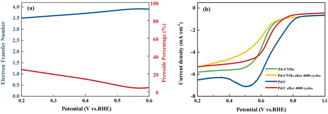 | ||
| Fig. 11 (a) The electron transfer number for ORR and peroxide percentage on Pd-CNMs. (b)The stability test of Pd-CNMs and commercial Pd/C. (In O2-saturated 0.1 M KOH, v = 10 mv s−1). | ||
4 Conclusion
In conclusion, PI-derived Pd-CNMs were prepared using an electrospinning and carbonization strategy. The high crystallinity and active zero-valent palladium particles were dispersed uniformly on the self-supported nanofiber films by adjusting the carbonization process. When the carbonization temperature was controlled at 800 °C, the as-obtained carbon fiber film had good synergistic catalytic activity with the catalyst. When the carbonization atmosphere was in a vacuum state, zero-valent palladium with high activity was formed. The as-obtained Pd-CNMs had excellent electrocatalytic ORR activity in an alkaline electrolyte.Data availability
No primary research results, software or code have been included and no new data were generated or analysed as part of this review.Conflicts of interest
There are no conflicts to declare.Acknowledgements
This work was financially supported by the Introduce Class Innovation leading Talents Long-term Project of Jiujiang City “Xuncheng talents” Plan (No. JJXC2023014) and Guangxi Key Laboratory of Information Materials (Grant No. 221018-K, 211012-K).References
- S. H. Hur and J. N. Park, Graphene and its application in fuel cell catalysis: a review, Asia-Pac, J. Chem. Eng., 2013, 8, 218–233 CAS.
- E. Antolini, Graphene as a new carbon support for low-temperature fuel cell catalysts, Appl. Catal., B, 2012, 123, 52–68 CrossRef.
- E. Antolini, Structural parameters of supported fuel cell catalysts: The effect of particle size, inter-particle distance and metal loading on catalytic activity and fuel cell performance, Appl. Catal., B, 2016, 181, 298–313 CrossRef CAS.
- J. Moreira, P. D. Angel, A. L. Ocampo, P. J. Sebastian, J. A. Montoya and R. H. Castellanos, Synthesis, characterization and application of a Pd/Vulcan and Pd/C catalyst in a PEM fuel cell, Int. J. Hydrogen Energy, 2004, 29, 915–920 CrossRef CAS.
- X. W. Yu and P. G. Pickup, Deactivation/reactivation of a Pd/C catalyst in a direct formic acid fuel cell (DFAFC): Use of array membrane electrode assemblies, J. Power Sources, 2009, 187, 493–499 CrossRef CAS.
- M. Z. Wang, X. P. Qin, K. Jiang, Y. Dong, M. H. Shao and W. B. Cai, Electrocatalytic activities of oxygen reduction reaction on Pd/C and Pd-B/C catalysts, J. Phys. Chem. C, 2017, 121, 3416–3423 CrossRef CAS.
- J. B. Xi, H. Y. Sung, D. Wang, Z. Y. Zhang, X. M. Duan, J. W. Xiao, F. Xiao, L. M. Liu and S. Wang, Confined-interface-directed synthesis of Palladium single-atom catalysts on graphene/amorphous carbon, Appl. Catal., B, 2018, 225, 291–297 CrossRef CAS.
- J. Yang, C. G. Tian, L. Wang and H. G. Fu, An effective strategy for small-sized and highly-dispersed palladium nanoparticles supported on graphene with excellent performance for formic acid oxidation, J. Mater. Chem., 2011, 21, 3384–3390 RSC.
- X. Fan, V. Sans, S. K. Sharma, P. K. Plucinski, V. A. Zaikovskii, K. Wilson, S. R. Tennison, A. Kozynchenko and A. A. Lapkin, Pd/C catalysts based on synthetic carbons with bi- and tri-modal pore-size distribution: applications in flow chemistry, Catal. Sci. Technol., 2016, 6, 2387–2395 RSC.
- F. Salman, C. Park and R. T. K. Baker, Hydrogenation of crotonaldehyde over graphite nanofiber supported nickel, Catal. Today, 1999, 53, 385–394 CrossRef CAS.
- C. Ruiz-García, F. Heras, N. Alonso-Morales, L. Calvo, J. J. Rodriguez and M. A. Gilarranz, Enhancement of the activity of Pd/C catalysts in aqueous phase hydrodechlorination through doping of carbon supports, Catal. Sci. Technol., 2018, 8, 2598–2605 RSC.
- R. M. Mironenko, O. B. Belskaya and V. A. Likholobov, Approaches to the synthesis of Pd/C catalysts with controllable activity and selectivity in hydrogenation reactions, Catal. Today, 2020, 357, 152–165 CrossRef CAS.
- L. Chong, J. G. Wen, J. Kubal, F. G. Sen, J. X. Zou, J. Greeley, M. Chan, H. Barkholtz, W. J. Ding and D. J. Liu, Ultralow-loading platinum-cobalt fuel cell catalysts derived from imidazolate frameworks, Science, 2018, 362, 1276 CrossRef CAS PubMed.
- R. Kour, S. Arya, S.-J. Young, V. Gupta, P. Bandhoria and A. Khosla, Recent advances in carbon nanomaterials as electrochemical biosensors, J. Electrochem. Soc., 2020, 167, 037555 CrossRef CAS.
- M. Zhenjun, G. Haorui and L. Xufeng, Recent advances of Pd/C-catalyzed reactions, Catalysts, 2021, 11, 1078 CrossRef.
- Y. J. Guo, X. Y. Wang, Y. Shen, K. Dong, L. Y. Shen and A. A. A. Alzalab, Research progress, models and simulation of electrospinning technology: a review, J. Mater. Sci., 2022, 57, 58–104 CrossRef CAS PubMed.
- Y. B. Liu and L. L. Guo, Homogeneous field intensity control during multi-needle electrospinning via finite element analysis and simulation, J. Nanosci. Nanotechnol., 2013, 13, 843–847 CAS.
- B. Wang, Y. Wang, Y. Lei, N. Wu, Y. Gou, C. Han, S. Xie and D. Fang, Mesoporous silicon carbide nanofibers with in situ embedded carbon for co-catalyst free photocatalytic hydrogen production, Nano Res., 2016, 9, 886–898 CrossRef CAS.
- Z. M. Mahdieh, S. Shekarriz, F. A. Taromi and M. Montazer, A new method for in situ synthesis of Ag-TiO2 nanocomposite particles on polyester/cellulose fabric by photoreduction and self-cleaning properties, Cellulose, 2018, 25, 2355–2366 CrossRef.
- K. B. Liew, W. R. W. Daud, M. Ghasemi, J. X. Leong, W. S. Lim and M. Ismail, Non-Pt catalyst as oxygen reduction reaction in microbial fuel cells: A review, Int. J. Hydrogen Energy, 2014, 39, 4870–4883 CrossRef.
- X. Chen, B. Liu, C. Zhong, Z. Liu, J. Liu, L. Ma, Y. D. Deng, X. P. Han, T. P. Wu, W. B. Hu and J. Lu, Ultrathin Co3O4 layers with large contact area on carbon fibers as high-performance electrode for flexible zinc-air battery integrated with flexible display, Adv. Energy Mater., 2017, 7, 11 Search PubMed.
- H. Y. Yuan, Y. Hou, I. M. Abu-Reesh, J. H. Chen and Z. He, Oxygen reduction reaction catalysts used in microbial fuel cells for energy-efficient wastewater treatment: a review, Mater. Horizons, 2016, 3, 382–401 RSC.
- Z. C. Xu, S. Y. Chen, S. Y. Guo, D. Wan, H. Xu, W. Yan, X. L. Jin and J. T. Feng, New insights in light-assisted microbial fuel cells for wastewater treatment and power generation: A win-win cooperation, J. Power Sources, 2021, 501, 18 CrossRef.
- J. Y. Song, S. Kim, J. Park and S. M. Park, Highly efficient, dual-functional self-assembled electrospun nanofiber filters for simultaneous PM removal and on-site eye-readable formaldehyde sensing, Adv. Fiber Mater., 2023, 5, 1088–1103 CrossRef CAS PubMed.
- T. H. Vignesh Kumar, J. Rajendran, R. Atchudan, S. Arya, M. Govindasamy, M. A. Habila and A. K. Sundramoorthy, Cobalt ferrite/semiconducting single-walled carbon nanotubes based field-effect transistor for determination of carbamate pesticides, Environ. Res., 2023, 238, 117193 CrossRef PubMed.
- S. Dutt, S. Verma, A. Singh, P. Mahajan, B. Padha, A. Ahmed, S.-J. Young, V. Gupta, D. N. Q. Agha and S. Arya, Flexible and highly stable textile-based symmetric supercapacitor comprising binder-free MnO2/rGO-CF nanocomposite electrodes, J. Electron. Mater., 2023, 52, 7447–7458 CrossRef CAS.
- V. Magesh, V. S. Kothari, D. Ganapathy, R. Atchudan, S. Arya, D. Nallaswamy and A. K. Sundramoorthy, Using sparfloxacin-capped gold nanoparticles to modify a screen-printed carbon electrode sensor for ethanol determination, Sensors, 2023, 23, 8201 CrossRef CAS PubMed.
- A. Ahmed, S. Verma, P. Mahajan, A. K. Sundramoorthy and S. Arya, Upcycling of surgical facemasks into carbon based thin film electrode for supercapacitor technology, Sci. Rep., 2023, 13, 12146 CrossRef CAS PubMed.
- D. Nan, Z. H. Huang, R. Lv, L. Yang, J. G. Wang, W. Shen, Y. Lin, X. Yu, L. Ye and H. Sun, Nitrogen-enriched electrospun porous carbon nanomember networks as high performance free-standing electrode materials, J. Mater. Chem. A, 2014, 2, 19678–19684 RSC.
- K. Naito, Y. Tanaka and J. M. Yang, Transverse compressive properties of polyacrylonitrile (PAN)-based and pitch-based single carbon fibers, Carbon, 2017, 118, 168–183 CrossRef CAS.
- Z. X. Zhang, H. D. Du, J. Li, L. Gan, S. W. Chiang, B. H. Li and F. Y. Kang, Preparation of aligned polyimide-based carbon nanofibers by electrospinning, New Carbon Mater., 2015, 30, 289–294 CAS.
- J. H. Zhu, S. Y. Wei, X. L. Chen, A. B. Karki, D. Rutman, D. P. Young and Z. H. Guo, Electrospun polyimide nanocomposite fibers reinforced with core-shell Fe-FeO nanoparticles, J. Phys. Chem. C, 2010, 114, 8844–8850 CrossRef CAS.
- Z. M. Hao, J. T. Wu, C. L. Wang and J. G. Liu, Electrospun polyimide/metal-organic framework nanofibrous membrane with superior thermal stability for efficient PM2.5 capture, ACS Appl. Mater. Interfaces, 2019, 11, 11904–11909 CrossRef CAS PubMed.
- N. T. Xuyen, H. K. Jeong, G. Kim, K. P. So, K. H. An and Y. H. Lee, Hydrolysis-induced immobilization of Pt(acac)2 on polyimide-based carbon nanofiber mat and formation of Pt nanoparticles, J. Mater. Chem., 2009, 19, 1283–1288 RSC.
- W. He, Preparation of carbon-supported Pd-rich nanocatalysts and their electrocatalytic performance for oxygen reduction reaction, Nanjing University of Aeronautics and Astronautics, 2011.
- O. Y. Podyacheva and Z. R. Ismagilov, Nitrogen-doped carbon nanomaterials: To the mechanism of growth, electrical conductivity and application in catalysis, Catal. Today, 2015, 249, 12–22 CrossRef CAS.
- Y. Cao, W. M. Si, Y. H. Zhang, Q. L. Hao, W. Lei, X. F. Xia, J. Li and F. G. Wang, Nitrogen-doped graphene: Effect of graphitic-N on the electrochemical sensing properties towards acetaminophen, FlatChem, 2018, 9, 1–7 CrossRef.
- G. Li, Y. Huang, Z. Yin, H. Guo and J. Wang, Defective synergy of 2D graphitic carbon nanosheets promotes lithium-ion capacitors performance, Energy Storage Mater., 2019, 24, 304–311 CrossRef.
- H. Xu, C. Yin, X. Hou, M. Gong, C. Yang, L. Xu, J. Luo, L. Ma, L. Zhou and X. Li, Polyimide-derived carbon nanofiber membranes as free-standing anodes for lithium-ion batteries, RSC Adv., 2022, 12, 21904–21915 RSC.
- A. I. Boronin, E. M. Slavinskaya, I. G. Danilova, R. V. Gulyaev, Y. I. Amosov, P. A. Kumetsov, I. A. Polukhina, S. V. Koscheev, V. I. Zaikovskii and A. S. Noskov, Investigation of palladium interaction with cerium oxide and its state in catalysts for low-temperature CO oxidation, Catal. Today, 2009, 144, 201–211 CrossRef CAS.
| This journal is © The Royal Society of Chemistry 2024 |

