
 Open Access Article
 This Open Access Article is licensed under a Creative Commons Attribution-Non Commercial 3.0 Unported Licence
Detection and photothermal inactivation of Gram-positive and Gram-negative bloodstream bacteria using photonic crystal biosensor and plasmonic core–shell
Ruth Birhanu Hayilesilassie*a,
Abebe Belay Gemta*a,
Fekadu Tolessa Maremia,
Alemayehu Getahun Kumela b,
Kusse Gudishec and
Bereket Delga Danac
b,
Kusse Gudishec and
Bereket Delga Danac
aDepartment of Applied Physics, School of Applied Natural Sciences, Adama Science and Technology University, P.O.Box 1888, Adama, Ethiopia. E-mail: abebebelay96@gmail.com; butaabush@gmail.com
bDepartment of Applied Physics, College of Natural and Computational Sciences, Mekdela Amba University, P.O.Box 032, Tullu Awulia, Ethiopia
cDepartment of Applied Physics, College of Natural and Computational Sciences, Jinka University, Jinka, Ethiopia
First published on 10th April 2024
Abstract
Plasmonics and core–shell nanomaterials hold great potential to develop pharmaceuticals and medical equipment due to their eco-friendly and cost effective fabrication procedures. Despite these advancements, combating drug-resistant bacterial infections remains a global challenge. Therefore, this study aims to introduce a tailored theoretical framework for a one-dimensional (1D) photonic crystal biosensor (PCB) composed of (ZrO2/GaN)N/defect layer/(ZrO2/GaN)N, designed to detect Gram-positive and Gram-negative bloodstream bacteria employing the transfer matrix method (TMM). In addition, using the finite difference methods (FDM), the photothermal inactivation of bloodstream bacteria with plasmonic core–shell structures (FeO@AuBiS2) was explored using key factors such as light absorption, heat generation, and thermal diffusion. By incorporating six dielectric layers and contaminated blood into the proposed PCB, a maximum sensitivity of 562 nm per RIU was recorded, and using rod-shaped plasmonic core–shell structures, 5.8 nm−1 light absorption capacity and 152 K change in temperature were achieved. The maximum detection sensitivity, light absorption, heat conduction and heat convection capacity of the proposed 1D PCB and plasmonic core–shell show an effective approach to combating drug-resistant bacteria.
1 Introduction
In recent years, detection and management of bloodstream infections caused by Gram-positive and Gram-negative bacteria have emerged as a critical challenge in healthcare setting.1,2 Traditional diagnostic methods (Abbe refractometer,3 comparing the liquid's refractive index to a known standard using a spectrometer,4 and Snell's law5) often involve time-consuming culturing processes, delay detection and potentially influence patient outcomes.6 Therefore, the advancement of modeling and experimental fabrication of photonic materials has garnered significant research attention, owing to their wide-ranging applications in imaging, drug delivery, sensing, and photothermal heat generation.7,8 Particularly in the field of photonic sensing, two widely adopted schemes are intensity reduction (IR) and resonant wavelength shift (RWS).9 The IR scheme revolves around measuring changes in light intensity to detect and quantify the presence of a target analyte. Which is accomplished by monitoring the reduction in the intensity of transmitted or reflected light using photodetectors or similar devices.10 While the RWS scheme relies on measuring changes in the resonant wavelength of light to detect and quantify target analyte, that can be achieved through spectrometry or wavelength interrogation techniques.11To leverage the unique light-analyte interaction and result in measurable signals, 1D, 2D, and 3D photonic crystals have been extensively studied.12–14 In 1D photonic crystals, the periodic structure enhances the light-analyte interaction by exploiting the unique properties of their layered architecture.15 Besides, in 2D photonic crystals, the periodic nanostructures are arranged in a 2D lattice to provide even greater control over the propagation of light, allowing for precise tuning of resonance conditions. This enables efficient coupling of light with the analyte molecules and facilitates the generation of strong and measurable biosignals.16 Further, in the case of 3D photonic crystals, the full 3D periodicity creates a highly intricate and sophisticated light confinement environment, resulting in unique band structures and photonic bandgaps to enable tighter control over the light-analyte interaction.17,18
Recently, several experimental fabrication schemes and theoretical modeling frameworks were extensively investigated. For example, Abadla et al., fabricated, cost-effective, and user-friendly 1D binary PCB to measure the refractive index of milk samples changes due to fat concentration. And they reported that, the proposed sensor would be processed in a signal processing unit give an accurate estimation of the fat concentration in milk.19 Besides, Huang et al., experimentally demonstrated an adjustable lattice orientation of 2D hexagonal PCB with thin gold film coating for Epstein–Barr virus protein detection. Their work provides a method of employing the cut-off wavelength of 2D PCB to benchmark the amount of specific bindings between antigens and antibodies.20 In addition, Kumar et al., designed 2-D photonic crystal double ring resonator-based biosensor using the finite-difference time-domain (FDTD) and plane wave expansion (PWE) methods. Their study focused on detecting the Chikungunya virus in normal and infected blood cells. The results showed a transmission efficiency of 98%, a sensitivity of 3430 nm per RIU, and a low quality factor of 60.21.21 Besides, Shojaeifar et al., investigated a ternary photonic crystal with a piezo layer and piezo defect layer, demonstrating versatile tun-ability as a narrow band-pass filter in the THz range.22 In addition, Razmjou et al., reported a 3D photonic crystal composed of zeolitic imidazolate framework-8, with a polydopamine (PDA) coating on a silicon substrate for detecting various blood components in the wavelength range of 1.1 to 1.5 μm using FDTD method.23 Overall, these studies illustrate that 1D photonic crystal biosensors are more efficient than their 2D and 3D counterparts due to their simple structure, simple fabrication, and integration into devices. The one-dimensional periodicity enhances the interaction between light and analytes, leading to stronger biosignals. Moreover, the straightforward design of 1D photonic crystals enables precise control over reflectance and transmittance properties, resulting in improved sensing performance and higher detection sensitivity.
In line with the need for an efficient detection mechanism, a promising approach to target bacterial inactivation is urgently required due to the development of antibiotic resistance by many bacteria.24,25 By utilizing the advantages of various materials that possess different light-to-heat conversion mechanisms based on their electronic or bandgap structure in response to electromagnetic radiation,26 several pioneers have revealed physical mechanisms for inactivating bacteria through heat,27 pressure,28 and radiation.29 Specifically, plasmonic core–shell (PCS) structures have the potential to contribute to bacterial inactivation through optical trapping, photothermal effects, and photochemical reactions.30 PCS-based photothermal inactivation (PTI)is a minimally invasive and drug-free treatment that uses specially engineered core–shell structures to efficiently absorb light of a specific wavelength that is highly absorbed by bacteria.31,32 The absorbed light energy is converted into localized heat, leading to an increase in temperature at the bacterial site.33 The temperature increase caused by the core–shell structures denatures proteins, destroys DNA, and impairs the integrity of cellular structures, ultimately resulting in bacterial inactivation or death.34
The efficacy of heat generation in the context of bacterial PTI is intricately tied to various factors such as the shape, size, and material composition of the core and shell of nanoparticles.35,36 Thus, several pioneers reported the experimental and theoretical investigations of nanoparticle mediated PTI for bacterial inactivation. Annesi et al., demonstrated the effective reduction of Escherichia coli population applying resonant laser irradiation of gold nanorods, the result shows, under near infrared illumination the temperature increase up to 50 oC in about 5 min.37 Besides, Xie et al., reported nanotip-engineered ZnO nanoarrays for photocatalytic bacteria remove, their work shows, ultrafast bactericidal rate of 97.5% for E. coli and 94.9% for S. aureus within 1 min.38 Further, Yang et al., developed a low-temperature PTT based on borneol-containing polymer-modified MXene nanosheets with the aid of near-infrared irradiation, and able to eradicate Staphylococcus aureus and Escherichia coli with more than 99.999% efficiency at ≤40 oC that is safe for the human body.39 While, photothermal therapy shows promise, further research is needed to optimize its efficacy against different bacteria strains, determine the optimal parameters (such as core–shell design, light wavelength, intensity, and duration), and assess its safety for clinical applications.33 The geometrical advantages of spherical, rod, and plate-shaped core–shell nanoparticles enable them to interact more effectively with incident light, leading to higher temperature heat generation compared to nanowires with similar shapes.40 In contrast, nanowires of the same shapes may have limitations in light absorption and scattering due to their elongated structure, resulting in reduced overall heat generation efficiency.41
The objective of this study is to develop a theoretical framework and computational model for a 1D PCB and plasmonic core–shell system, with the goal of detecting and inactivating both Gram-positive and Gram-negative bacteria using photothermal methods. In order to assess the effect of the number of dielectric layers on the performance of the 1D PCB, the TMM was used to calculate sensitivity measurement parameters such as sensitivity, quality factor, and figure of merit. An optimal temperature was also determined for the photothermal inactivation of bloodstream bacteria to understand heat transfer dynamics and the interaction between laser light and core–shell structures.
2 Analytical model
2.1 Design analysis of photonic crystal biosensor
The main attractive optical future of photonic crystals is the ease to tune the photonic band gap (PBG) by optimizing the thickness and special characteristics of RI of each layer.42 Hence, it allows us to hinder certain wavelength ranges from transmitting through the structure.43 Thus, we plan a 1D PCB to be arranged as illustrated in Fig. 1. ZrO2 is chosen for its outstanding optical properties, including transparency to visible light, excellent optical clarity, relatively low thermal conductivity, and thermal stability.44 These qualities make it ideal for use in high-temperature environments without compromising its optical performance.19 In addition, GaN has been chosen for its unique optical properties (including a wide bandgap, allowing efficient operation in the ultraviolet and visible light spectrum; a high refractive index, enabling effective light confinement and manipulation crucial for enhancing biosensor sensitivity and selectivity; low optical losses essential for maintaining a high signal-to-noise ratio; and chemical stability and resistance to corrosion, making it suitable for long-term and reliable operation in biological sensing environments),45,46 making it an ideal dielectric layer for PCB. Hence, as the constituents are arranged in a multi-layer structure, the TMM was used to model light interaction with the materials in the structure.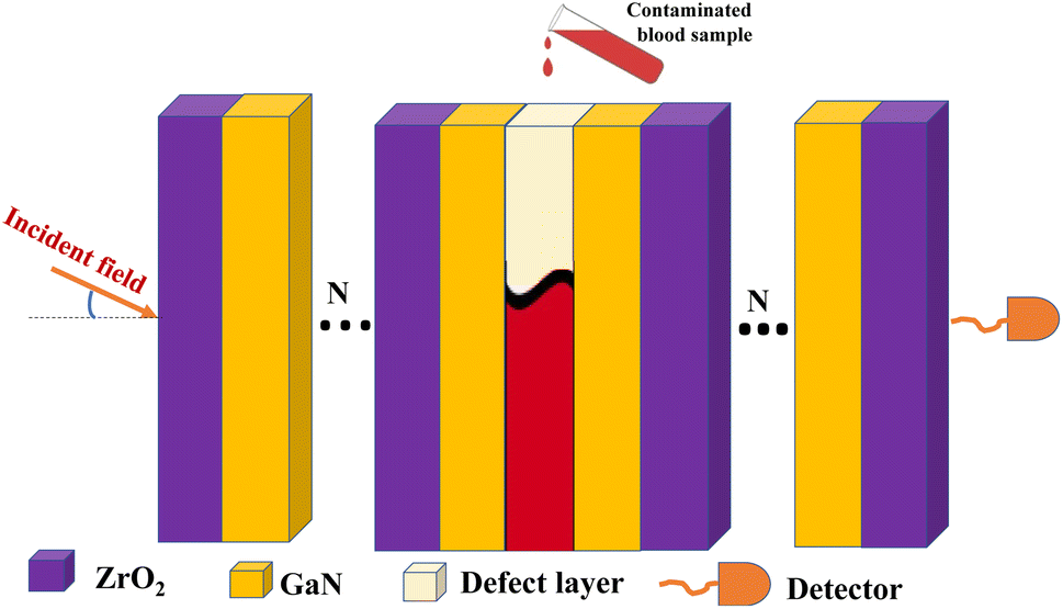 | ||
| Fig. 1 Schematic diagrams of the propsed one-dimensional photonic crystal biosensor. | ||
Following, employing TMM the optical parameters such as refractive index, thickness of layers, and absorption coefficients are used to calculate the transmission and reflection of light through multi-layer structures. Therefore, the refractive index of each photonic crystal constituents are dispensed in eqn (1) and (2) as,19,45
 | (1) |
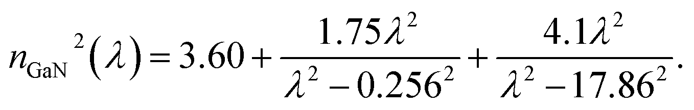 | (2) |
Furthermore, Gram-positive bacteria possess a robust peptidoglycan cell wall that retains the crystal violet stain during the gram staining process,47 while Gram-negative bacteria feature a thinner peptidoglycan layer surrounded by an outer membrane containing lipopolysaccharides.48 This difference in cell wall composition contributes to Gram-negative bacteria having a higher refractive index compared to Gram-positive bacteria.49 This structural variation plays a significant role in determining their response to antibiotics, susceptibility to disinfectants, and overall pathogenicity.47,48 The refractive index values of the bacteria used in this study are presented in Table 1.
The RI variation due to concentration type and level variation of contaminated human blood cell takes the form,56
| nCB = nNB + RIscons. | (3) |
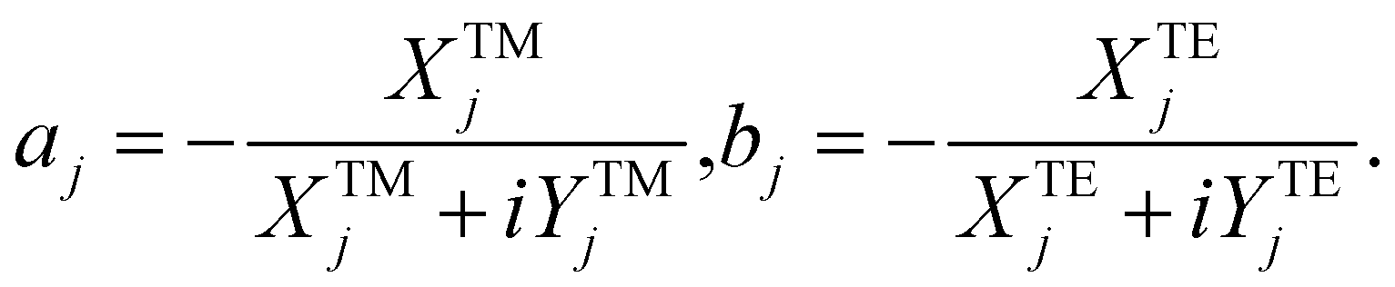
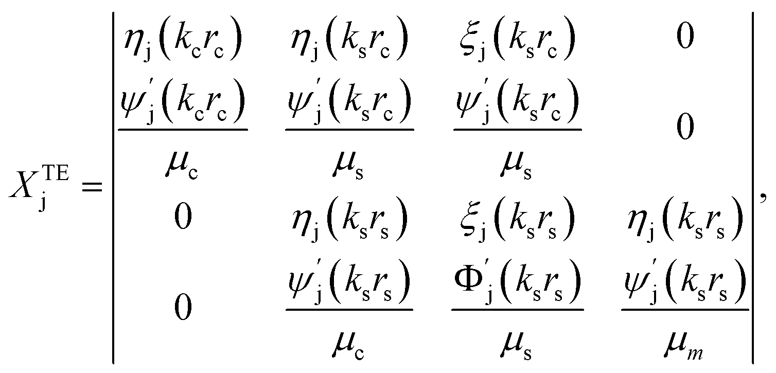
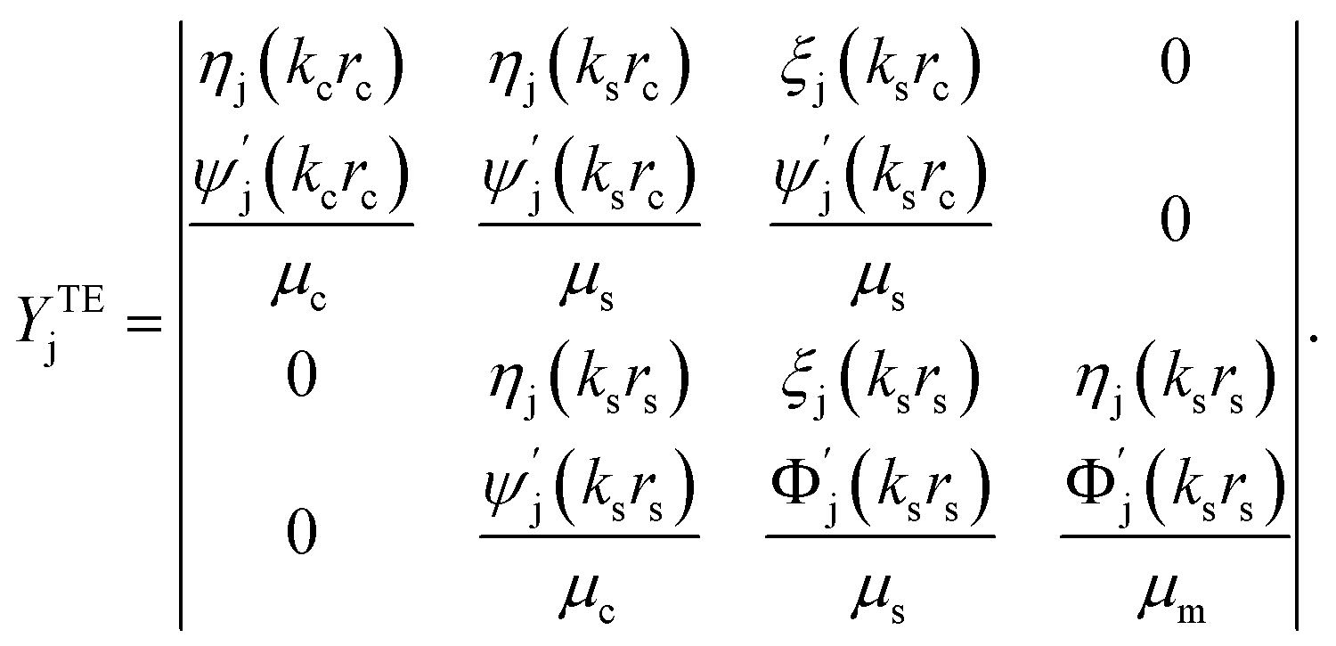
To this end, the interaction of incident light field with proposed photonic crystal can be expressed by TMM using,19
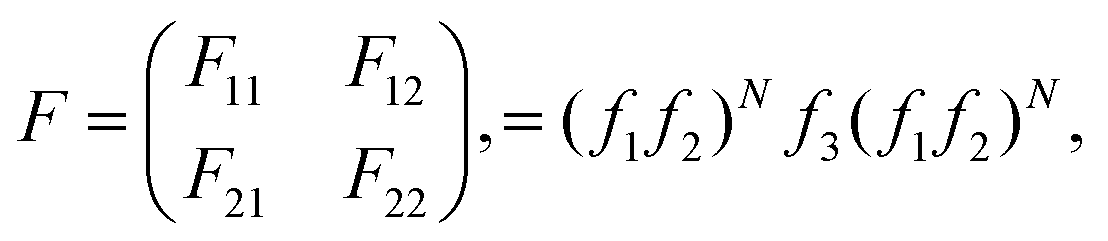 | (4) |
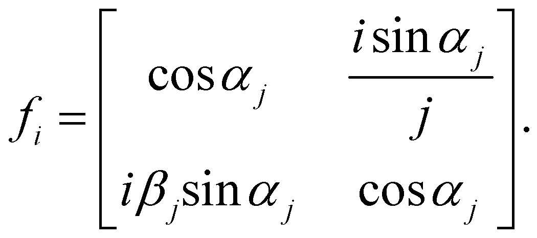 | (5) |
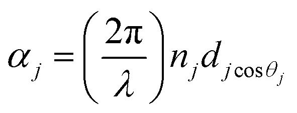 ,
, 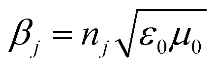 , and
, and 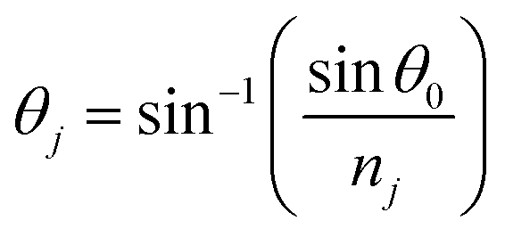 in which λ is pumping wavelength, dj is thickness of each layer, ε0 is permittivity of free space, μ0 is permeability of free space, and θ0 is angle of incidence for transverse electric (TE) mode.
Following this, the reflectivity (R) in-terms of reflection coefficient (r) takes the from,57
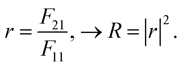 | (6) |
Employing eqn (6) the reflectivity versus wavelength will plotted to dispensed the sensors performance of proposed biosensor in-terms of sensitivity 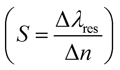 ,19 quality factor (QF = Δλres/FWHM),
 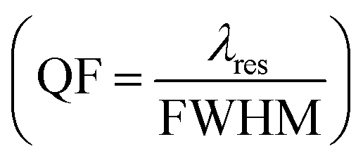 figure of merit 45 and resolution limit
 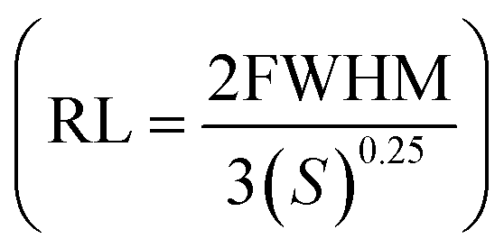 58 will dispensed in Section 3.
In addition to the theoretical analysis, the authors recommend following experimental procedures for practical fabrication of the proposed biosensor: start by preparing cost-effective zirconium and oxygen precursors, such as zirconium alkoxides or salts.59 Then, create a sol by dissolving the zirconium precursor in a solvent like ethanol to obtain a uniform solution, adding water for hydrolysis and polycondensation, ensuring proper mixing while controlling pH. Next, let the gel age to solidify, forming a structured network. By optimizing parameters like precursor concentration and solvent choice, the sol–gel method can efficiently synthesize ZrO2 for photonic crystal applications.60 For GaN substrate synthesis, consider hydride vapor phase epitaxy (HVPE) for fast growth rates and follow with ammonothermal growth for high-quality GaN crystals.61 In addition, in preparing defect layer some physical properties like biocompatiblty, and functional groups that optimize biomolecular binding affinity are must be considered.
Following the substrate preparation, the assembly of the proposed PCB follows a set of recommended procedures. Firstly, GaN film is ablated onto a ZrO2 substrate using pulsed laser deposition under controlled conditions to ensure uniformity and minimal defects. This technique is repeated based on the number of dielectric layers (N) utilized. Pulsed laser deposition (PLD) is chosen for its precision and control in producing high-quality thin films. Next, to deposit a defect layer onto the GaN substrate, start by creating a mask on the GaN surface using lithography to outline areas for defect formation. Then, use reactive ion etching (RIE) to selectively remove GaN material in the masked regions, inducing controlled defects. And deposit dielectric substrate onto defect layer following the above techniques. Finally, confirm the formation of the defect layer through SEM imaging and electrical characterization to guarantee improved biosensor sensitivity and performance. The overall assembly procedure is outlined in Fig. 2.
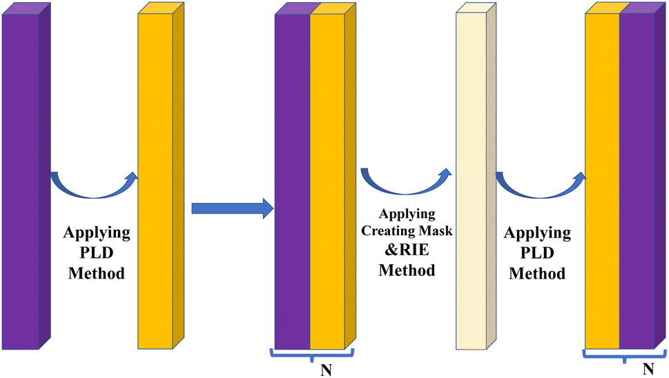 | ||
| Fig. 2 Schematic diagram of each steps for experimental fabrication of proposed one-dimensional photonic crystal biosensor. | ||
2.2 Theoretical model of plasmonic core–shell heat generation
The theoretical model of the photothermal response of core–shell structures involves understanding the underlying physical processes and developing mathematical equations to describe the heat generation and transfer mechanisms.62,63 This helps in predicting and optimizing the behavior of core–shell structures under different light sources, material properties, and geometries.64 Therefore, in this work we proposed spherical, rod, and plate shaped FeO@AuBiS2 core–shell that arranged as shown in Fig. 3. In selecting shape we consider: spherical geometry ensures light absorption from all directions, enabling effective light absorption and conversion into heat.65 Rod-shaped core–shell nanoparticles offer adjustable aspect ratios that enhance interaction with incident light, promoting efficient heat conversion.66 Plate-shaped core–shell nanoparticles provide a large surface area, facilitating improved light absorption and enhancing their capacity for heat generation.67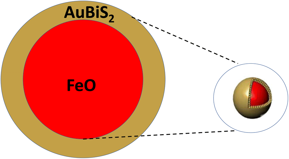 | ||
| Fig. 3 Schematic diagrams of the proposed core–shell structures. | ||
In addition, in selecting shell (AuBiS2), the exceptional plasmonic property, production of reactive oxygen species, photothermal conversion efficiency, and excellent chemical properties are considered.68 In addition, FeO is selected for its high photon absorption that used to cool the overheated cell.69
The first step to express light-to-heat conversion process is calculated employing absorption cross-sections (Cabs), extinction coefficients (Cext), and light absorption capacity (Aabs),70 using well known Mie theory is given by eqn (7) to (9),71,72
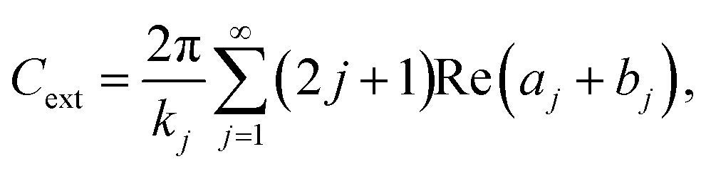 | (7) |
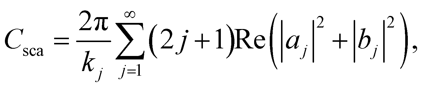 | (8) |
| Cabs = Cext − Csca. | (9) |
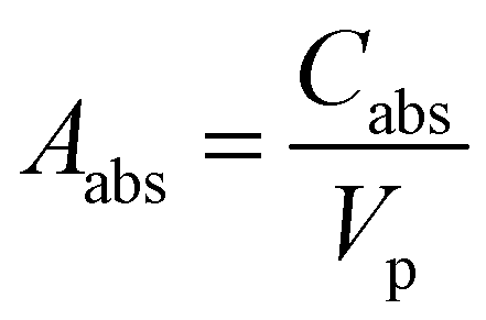 , for volume of nanosphere (Vp = 4/3πrj3), volume of nanorod (Vp = πrj2l here l is length of rod), and volume of plate (Vp = πrj2t t is thickness of plate core–shell). Where,
 | (10) |
 | (11) |
 | (12) |
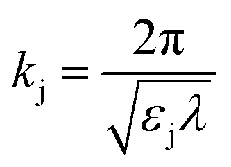 is wave number for εj is permittivity in which j = c,s,m.
Once the light is absorbed by the core–shell structure, it is converted into heat through various mechanisms, such as electron-phonon relaxation, nonradiative transitions, and phonon–phonon interactions.73 The absorbed energy is transformed into heat, causing increase in temperature that expressed by conversion efficiency.74  Here, C is specific heat, m is mass of proposed core–shell, P is power density of incident light, A is radiation area, and τ is radiation time. The main focus of this work is inactivation of bloodstream bacteria in blood sample, so the heat flow of from core–shell (light absorber) to the sample (contaminated blood sample) is given by conduction energy
  , where, ξ is thermal conductivity, L is conduction length, and Tcs and Tsam are temperature raised by core–shell and temperature of sample respectively. Hence the proposed sample is fluid, the heat energy transfer induced by movement of fluid is given by convection energy (Hconv = ChA(Tcs − Tsam), for Ch is heat transfer coefficient). Further, by applying quasi static electromagnetic field equation, the relation between change in temperature (ΔT) and absorption coefficient resulted from chemical and physical characteristics of sample, core–shell and pumping laser takes the form,75
 | (13) |
To experimentally fabricate FeO@AuBiS2 core–shell structures, begin by synthesizing FeO nanoparticles through a method such as co-precipitation or thermal decomposition.76 Next, prepare the AuBiS2 shell by adding gold and bismuth precursors to a sulfur-containing solution under controlled conditions to facilitate shell formation around the FeO nanoparticles.68 Utilize techniques like solvothermal or sonochemical methods for the core–shell assembly, ensuring proper shell growth and uniform coverage.77 Characterize the FeO@AuBiS2 core–shell structures using analytical techniques like transmission electron microscopy (TEM) and X-ray diffraction (XRD) to confirm the presence of the core and shell components.78 Adjust synthesis parameters such as precursor concentrations and reaction times to optimize the core–shell structure for potential photothermal applications.
3 Result and discussions
The numerical analysis procedures for optimizing the sensitivity of the proposed 1D PCB structure for detecting bloodstream bacteria were detailed in eqn (1)–(6). Using Matlab2023b, we characterized the spectral response by varying the number of dielectric layers (refer to Fig. 4) and adjusting the concentration of bacterial-infected blood (refer to Fig. 5). (Fig. 4a–c) clearly demonstrate that with an increase in the number of dielectric layers, the PBG of the proposed structure expands due to each additional layer introduces new opportunities for light waves to be filtered out based on their frequencies, resulting in a broader PBG that covers a wider range of wavelengths. However, beyond the optimal number of layers (N = 6), the PBG diminishes (as shown in Fig. 4d and e) as a fact that as the number of dielectric layers 1D PCB increased beyond the optimal point, the constructive interference that initially contributed to the formation of the PBG can experience interference patterns that lead to destructive interference, this agree with recently reported literature.79,80 In addition, (Fig. 4f) illustrates the electric field profile within the photonic crystal structure at the optimal number of dielectric layers.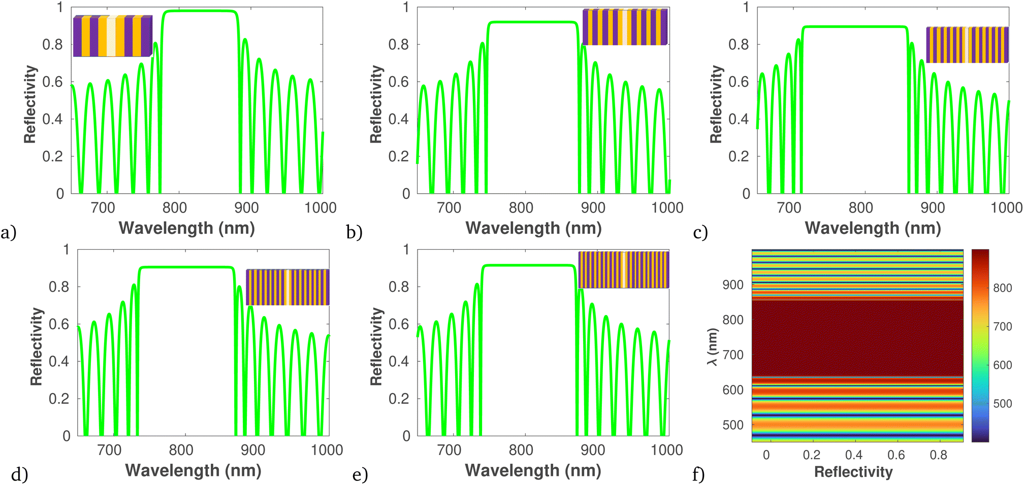 | ||
| Fig. 4 Plot of photonic band structure of different number of dielectric layer versus wavelength at T = 20 oC, and angle of incidence 60°. (a) N = 2, (b) N = 4, (c) N = 6, (d) N = 8, (e) N = 10, and (f) electric field profile for N = 6, plotted using Matlab2023b. | ||
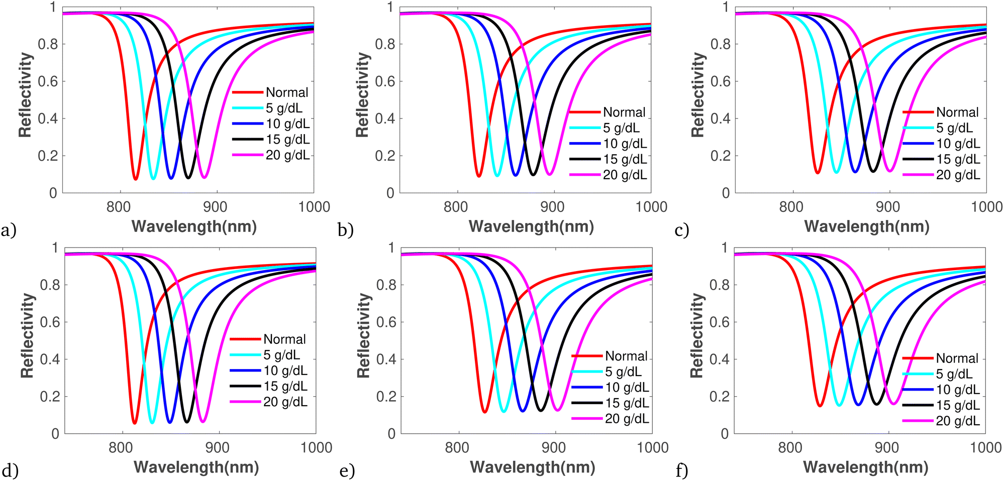 | ||
| Fig. 5 Plot of reflectivity versus wavelength under band edge modes for different concentration of bacteria contaminated blood, using data presented in Table.1, at T = 20 oC, and angle of incidence 60°. (a) Bacillus anthracis, (b) Streptococcus haemolyticus, (c) Staphylococcus aureus, (d) Pseudomonas aeruginosa, (e) Serratia marcescens, (f) Escherichia coli. | ||
Further, using the data provided in (Fig. 4a–e), Table 2 illustrates the comprehensive performance analysis of each number of dielectric layers. The result reveals that as the PBG increases, there is a corresponding increase in S, FoM, QF, and RL.
| Number of layer | Δλres (nm) | Δn | FWHM | S (nm per RIU) | FoM | QF (RIU−1) | RL |
|---|---|---|---|---|---|---|---|
| 2 | — | — | 35 | — | — | — | — |
| 4 | 20 | 0.1 | 57.5 | 200 | 3.47 | 0.347 | 144.16 |
| 6 | 15 | 0.025 | 75 | 600 | 8 | 0.20 | 247.46 |
| 8 | 13 | 0.03 | 78 | 433.3 | 5.56 | 0.170 | 237.20 |
| 10 | 12 | 0.038 | 81 | 316 | 3.90 | 0.148 | 227.68 |
Moreover, Fig. 5 displays the reflectivity versus wavelength for bacterial-contaminated blood samples, specifically GP (Fig. 5a–c) and GN (Fig. 5c–f), with varying concentrations and specifications while keeping the number of dielectric layers fixed to optimal sensitivity under band edge modes.81 The figures clearly demonstrate that as the sample concentration increases, the reflectivity spectra broaden and shift towards longer wavelengths, leading to a broader FWHM. Hence, the sample concentration increases can be attributed to the increased refractive index contrast, changes in the effective optical path length, and the influence of surface plasmon resonance effects induced by the binding of analyte molecules. These effects collectively alter the spectral response of the photonic crystal biosensor, providing valuable information about the concentration and interaction of biomolecules with the sensor surface. Additionally, the sensitivity variations at each sample concentration are illustrated in Table 3. Thus Table 3 reveal the maximum S of 562 nm per RIU, FoM of 0.232, QF of 196.03/RIU, and RL of 0.697 that outperform recently reported work of.19
| BS | BN | Cons. | Δλres (nm) | Δn | FWHM | S (nm per RIU) | FoM | QF (RIU−1) | RL |
|---|---|---|---|---|---|---|---|---|---|
| GP | BA | 5 | 0.47 | 0.0025 | 2.02 | 188 | 0.232 | 93.06 | 0.363 |
| 10 | 0.3 | 0.0014 | 2.19 | 214.28 | 0.136 | 97.84 | 0.381 | ||
| 15 | 0.28 | 0.0010 | 2.53 | 280 | 0.110 | 110.67 | 0.412 | ||
| 20 | 0.17 | 0.00032 | 2.71 | 531.25 | 0.062 | 196.03 | 0.376 | ||
| SH | 5 | 0.50 | 0.002 | 2.8 | 250 | 0.178 | 89.28 | 0.469 | |
| 10 | 0.45 | 0.0017 | 3.1 | 264.70 | 0.145 | 85.38 | 0.512 | ||
| 15 | 0.42 | 0.001 | 3.33 | 276.31 | 0.126 | 82.97 | 0.544 | ||
| 20 | 0.37 | 0.00089 | 3.69 | 415.73 | 0.100 | 112.66 | 0.545 | ||
| SA | 5 | 0.52 | 0.0021 | 3.17 | 247.61 | 0.164 | 78.11 | 0.532 | |
| 10 | 0.48 | 0.0018 | 3.42 | 266.67 | 0.140 | 77.97 | 0.564 | ||
| 15 | 0.43 | 0.0015 | 4.06 | 286.67 | 0.105 | 7.60 | 0.651 | ||
| 20 | 0.41 | 0.0010 | 4.08 | 410 | 0.100 | 100.49 | 0.604 | ||
| GN | PA | 5 | 0.51 | 0.003 | 2.1 | 170 | 0.124 | 80.95 | 0.387 |
| 10 | 0.50 | 0.0028 | 2.40 | 178.5 | 0.208 | 74.37 | 0.437 | ||
| 15 | 0.48 | 0.0021 | 2.58 | 228.57 | 0.186 | 88.59 | 0.442 | ||
| 20 | 0.46 | 0.0011 | 2.95 | 418.18 | 0.155 | 141.75 | 0.434 | ||
| SM | 5 | 0.53 | 0.0028 | 3.28 | 189.28 | 0.161 | 57.70 | 0.589 | |
| 10 | 0.51 | 0.0025 | 3.57 | 204 | 0.142 | 57.14 | 0.629 | ||
| 15 | 0.48 | 0.0016 | 3.97 | 300 | 0.120 | 68.18 | 0.635 | ||
| 20 | 0.47 | 0.0010 | 4.4 | 470 | 0.106 | 106.81 | 0.630 | ||
| EC | 5 | 0.55 | 0.0032 | 3.67 | 171.87 | 0.149 | 46.83 | 0.675 | |
| 10 | 0.53 | 0.0028 | 3.88 | 189.28 | 0.136 | 48.78 | 0.697 | ||
| 15 | 0.51 | 0.0021 | 3.90 | 242.85 | 0.130 | 62.26 | 0.658 | ||
| 20 | 0.50 | 0.00089 | 4.51 | 561.79 | 0.110 | 124.56 | 0.617 |
Finally, we have performed a comparative analysis of our result with recent studies conducted between 2021 and 2024. The data gathered from this study has been collated and is summarized in Table 4. The outcomes underscore the potential of the proposed structure for integration into the development of exceptionally sensitive biophotonic sensors.
| Sample | PCB arrangement | Method | S (nm per RIU) | QF (RIU−1) | FoM | Ref. |
|---|---|---|---|---|---|---|
| Glucose | 2D | PWE and FDTD | 795 | 53.5 | 33.07 | 82 |
| Glucose | 1D ternary | TMM | 768.3 | 1239.3 | 394.017 | 83 |
| Blood | 1D binary | TMM | 71.25 | 20.96 | — | 84 |
| Blood | 1D binary | TMM | 203.09 | 1569 | 0.0093 | 85 |
| Blood | 2D | FDTD | 217.5 | — | 817.66 | 86 |
| Biotargets | CCW | PWE and FDTD | 203 | — | 13![[thin space (1/6-em)]](https://www.rsc.org/images/entities/char_2009.gif) 360 360 |
87 |
| Blood | 1D binary | TMM | 562 | 124.6 | 0.110 | This work |
On the other hand, the photothermal response of the proposed core–shell structure is illustrated in Fig. 6 using eqn (8). It is evident that as the radius, thickness, and length of the core–shell increase, the absorption cross-section also increases. Comparing (Fig. 6a–f), it is apparent that core–shell structures in rod shapes exhibit the highest light absorption capacity of 5.8 nm−1. Subsequently, the heat conversion analysis of the proposed core–shell is presented in Table 5. The data clearly indicates that an increase in the size of the core–shell results in a greater temperature difference within the sample, attributed to the increased distance for heat transfer. This leads to a reduction in the rates of heat conduction and convection as the larger core–shell size diminishes the efficiency of heat transfer across the structure. Moreover, comparing the heat generated by proposed core–shell with other modalities of heat based bacteria inactivation, it is evident that the proposed work can effectively used to inactivate both Gram-positive and Gram-negative bacteria.88–90
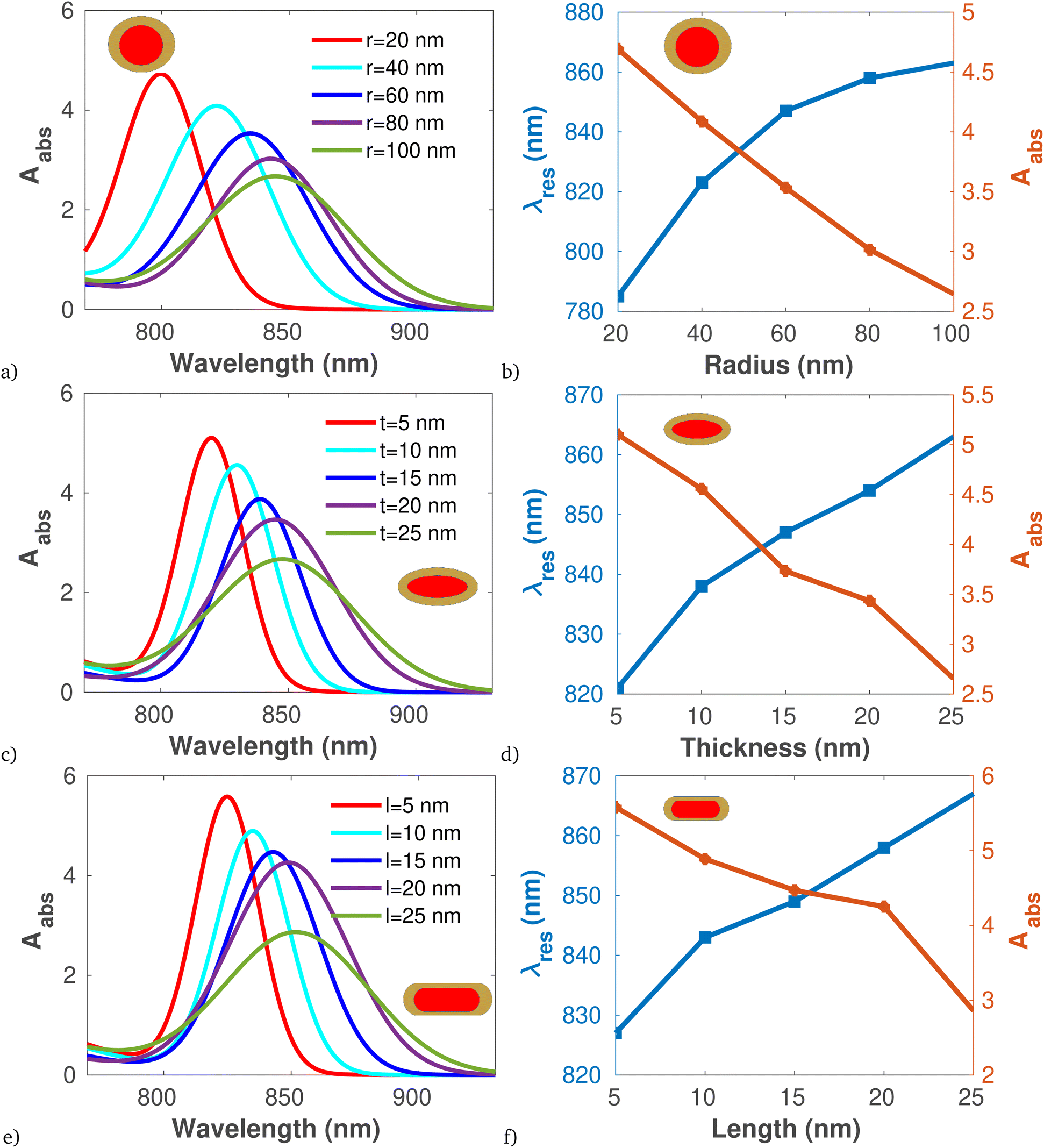 | ||
| Fig. 6 Plot of Absorption cross section and resonant peak versus wavelength and thickness for different shape of core–shell using data presented in Table 1, at 808 nm pumping wave length. (a)and (b) Spherical core–shell. (c and d) Plate shaped core–shell. (e and f) Rod shaped core–shell. | ||
| Core–shell shape | Parameters | Hcon | Hconv | ΔT |
|---|---|---|---|---|
| Sphere | r = 10 nm | 65.831 | 0.543 | 95.46 |
| r = 15 nm | 57.71 | 0.817 | 125.53 | |
| r = 20 nm | 51.214 | 1.087 | 148.52 | |
| r = 25 nm | 45.89 | 1.360 | 166.37 | |
| Plate | t = 5 nm, r = 10 nm | 66.43 | 0.522 | 96.32 |
| t = 10 nm, r = 15 nm | 58.44 | 0.783 | 127.10 | |
| t = 15 nm, r = 20 nm | 52.01 | 1.044 | 158.83 | |
| t = 20 nm, r = 25 nm | 46.73 | 1.305 | 169.420 | |
| Rod | l = 5 nm, r = 10 nm | 66.76 | 0.509 | 96.81 |
| l = 10 nm, r = 15 nm | 58.85 | 0.764 | 128 | |
| l = 15 nm, r = 20 nm | 52.46 | 1.02 | 152.16 | |
| l = 20 nm, r = 25 nm | 47.21 | 1.27 | 171.16 |
4 Conclusion
In summary, to evaluate the sensing performance of the proposed biosensor, we initially conducted a numerical analysis of reflection spectra with varying dielectric layers and concentrations of bacterial-contaminated blood using TMM. The simulation results revealed a maximum sensitivity of 600 nm per RIU for N = 6. Additionally, for N = 6 when incorporating bacterial-infected blood samples into defect layers, a sensitivity of 562 nm per RIU was achieved. Furthermore, utilizing Mie theory, we explored the heat generation capabilities of core–shell structures by adjusting their shape, diameter, thickness, and length. The findings indicated that rod-shaped core–shells produced temperature changes ranging from 40 oC to 80 oC, demonstrating effectiveness in deactivating both Gram-positive and Gram-negative bacteria.Data availability
Data underlying the results presented in this paper are not publicly available at this time but may be obtained from the authors upon reasonable request.Conflicts of interest
The authors declare that they have no known competing financial interests or personal relationships that could have appeared to influence the work reported in this paper.Acknowledgements
The first author thanks Mekdela Amba University for partial sponser this work.References
- D. Giacobbe, T. Giani, M. Bassetti, A. Marchese, C. Viscoli and G. Rossolini, Clin. Microbiol. Infect., 2020, 26, 713–722 CrossRef CAS PubMed.
- R. Birhanu, A. B. Gemta, F. Tolessa Maremi and A. G. Kumela, J. Opt., 2024, 1–12 Search PubMed.
- I. Y. Yanina, A. P. Popov, A. V. Bykov, I. V. Meglinski and V. V. Tuchin, J. Biomed. Opt., 2018, 23, 016003 Search PubMed.
- S. Kedenburg, M. Vieweg, T. Gissibl and H. Giessen, Opt. Mater. Express, 2012, 2, 1588–1611 CrossRef CAS.
- A. V. Shukla, Clinical optics primer for ophthalmic medical personnel: a guide to laws, Formulae, Calculations, and Clinical Applications, Slack Incorporated, 2009 Search PubMed.
- M. Pradella, R. M. Dorizzi, F. Rigolin and B. E. Statland, Crit. Rev. Clin. Lab. Sci., 1988, 26, 195–242 CrossRef CAS PubMed.
- M. T. Sohail, M. Wang, M. Shareef and P. Yan, Infrared Phys. Technol., 2024, 105127 CrossRef CAS.
- Z. Zhang, H. Zhu, W. Zhang, Z. Zhang, J. Lu, K. Xu, Y. Liu and V. Saetang, Carbon, 2023, 118356 CrossRef CAS.
- M. Al Mahfuz, M. A. Hossain, E. Haque, N. H. Hai, Y. Namihira and F. Ahmed, IEEE Sens. J., 2020, 20, 7692–7700 CAS.
- A. Ahmadivand and B. Gerislioglu, Laser Photonics Rev., 2022, 16, 2100328 CrossRef CAS.
- A. A. Rifat, G. A. Mahdiraji, Y. Shee, M. J. Shawon and F. M. Adikan, Procedia Eng., 2016, 140, 1–7 CrossRef CAS.
- G. M. Paterno, L. Moscardi, S. Donini, D. Ariodanti, I. Kriegel, M. Zani, E. Parisini, F. Scotognella and G. Lanzani, J. Phys. Chem. Lett., 2019, 10, 4980–4986 CrossRef CAS PubMed.
- Y.-L. Ji, L.-X. Gao and Y. Tian, Mater. Adv., 2023, 4, 542–550 RSC.
- Y. Xu, P. Bai, X. Zhou, Y. Akimov, C. E. Png, L.-K. Ang, W. Knoll and L. Wu, Adv. Opt. Mater., 2019, 7, 1801433 CrossRef.
- A. Getahun, A. B. Gemta, A. Kebede, R. Birhanu, H. D. Mekonnen, U. Sherefedin and K. Woldegiorges, Nanoscale Adv., 2023, 5, 6382–6399 RSC.
- T. Lu, W. Peng, S. Zhu and D. Zhang, Nanotechnology, 2016, 27, 122001 CrossRef PubMed.
- S. Feng, J.-H. Jiang, A. Al Rashid and S. John, Opt. Express, 2016, 24, 12166–12191 CrossRef CAS PubMed.
- J. Li and K. Nallappan, Opt. Mater. Express, 2019, 9, 1640–1653 CrossRef CAS.
- K. M. Abohassan, H. S. Ashour and M. M. Abadla, RSC Adv., 2021, 11, 12058–12065 RSC.
- Y.-T. Chen, Y.-Y. Liao, C.-C. Chen, H.-H. Hsiao and J.-J. Huang, Sens. Actuators, B, 2019, 291, 81–88 CrossRef CAS.
- S. Sharma, A. Kumar, K. S. Singh and H. K. Tyagi, Optik, 2021, 237, 166575 CrossRef CAS.
- A. S. Firouzjaei, D. Kalhor, M. Shojaeifar and H. Goudarzi, Optik, 2023, 288, 171248 CrossRef CAS.
- M. Nankali, Z. Einalou, M. Asadnia and A. Razmjou, ACS Appl. Bio Mater., 2021, 4, 1958–1968 CrossRef CAS PubMed.
- T. Yu, G. Jiang, R. Gao, G. Chen, Y. Ren, J. Liu, H. C. van der Mei and H. J. Busscher, Expert Opin. Drug Delivery, 2020, 17, 1151–1164 CrossRef CAS PubMed.
- A. S. Ezeuko, M. O. Ojemaye, O. O. Okoh and A. I. Okoh, J. Water Proc. Eng., 2021, 41, 102041 CrossRef.
- J. U. Kim, S. Lee, S. J. Kang and T.-i. Kim, Nanoscale, 2018, 10, 21555–21574 RSC.
- R. Lv, D. Liu and J. Zhou, Curr. Opin. Food Sci., 2021, 42, 31–36 CrossRef.
- R. Sehrawat, B. P. Kaur, P. K. Nema, S. Tewari and L. Kumar, Food Sci. Biotechnol., 2021, 30, 19–35 CrossRef PubMed.
- P. Shaw, N. Kumar, S. Mumtaz, J. S. Lim, J. H. Jang, D. Kim, B. D. Sahu, A. Bogaerts and E. H. Choi, Sci. Rep., 2021, 11, 14003 CrossRef CAS PubMed.
- Y. Zhang, H. Yan, J. Tang, P. Li, R. Su, H. Zhong and W. Su, J. Photochem. Photobiol., A, 2022, 425, 113722 CrossRef CAS.
- A. Gharatape, S. Davaran, R. Salehi and H. Hamishehkar, RSC Adv., 2016, 6, 111482–111516 RSC.
- S. Mondal, J. L. Montaño-Priede, S. Park, J. Choi, V. H. M. Doan, T. M. T. Vo, T. H. Vo, N. Large, C.-S. Kim and J. Oh, et al., J. Adv. Res., 2022, 41, 23–38 CrossRef CAS PubMed.
- G. Guan, K. Y. Win, X. Yao, W. Yang and M.-Y. Han, Adv. Healthcare Mater., 2021, 10, 2001158 CrossRef CAS PubMed.
- D. Hu, L. Zou, B. Li, M. Hu, W. Ye and J. Ji, ACS Biomater. Sci. Eng., 2019, 5, 5169–5179 CrossRef CAS PubMed.
- H. Liu, F. Xing, Y. Zhou, P. Yu, J. Xu, R. Luo, Z. Xiang, P. M. Rommens, M. Liu and U. Ritz, Mater. Des., 2023, 112231 CrossRef CAS.
- X. Qi, Y. Xiang, E. Cai, X. Ge, X. Chen, W. Zhang, Z. Li and J. Shen, Coord. Chem. Rev., 2023, 496, 215426 CrossRef CAS.
- F. Annesi, A. Pane, M. A. Losso, A. Guglielmelli, F. Lucente, F. Petronella, T. Placido, R. Comparelli, M. G. Guzzo and M. L. Curri, et al., Materials, 2019, 12, 1530 CrossRef CAS PubMed.
- Y. Xie, X. Qu, J. Li, D. Li, W. Wei, D. Hui, Q. Zhang, F. Meng, H. Yin and X. Xu, et al., Sci. Total Environ., 2020, 738, 139714 CrossRef CAS PubMed.
- N. J. Yang and I. M. Chiu, J. Mol. Biol., 2017, 429, 587–605 CrossRef CAS PubMed.
- J. Boken, P. Khurana, S. Thatai, D. Kumar and S. Prasad, Appl. Spectrosc. Rev., 2017, 52, 774–820 CrossRef CAS.
- V. Kudryavtseva and G. B. Sukhorukov, Adv. Mater., 2024, 2307675 CrossRef CAS PubMed.
- R. K. Gangwar, A. K. Pathak and S. Kumar, Photonics, 2023, 1199 CrossRef CAS.
- K. Zhu, C. Fang, M. Pu, J. Song, D. Wang and X. Zhou, J. Mater. Sci. Technol., 2023, 141, 78–99 CrossRef CAS.
- S. Bhaskar, E. W. Awin, K. H. Kumar, A. Lale, S. Bernard and R. Kumar, Sci. Rep., 2020, 10, 430 CrossRef CAS PubMed.
- A. H. Aly, B. Mohamed, S. Awasthi, S. A. O. Abdallah and A. Amin, Sci. Rep., 2023, 13, 9422 CrossRef CAS PubMed.
- Y.-n. Zhang, Y. Zhao and R.-q. Lv, Sens. Actuators, A, 2015, 233, 374–389 CrossRef CAS.
- M. J. Wilhelm, J. B. Sheffield, M. Sharifian Gh, Y. Wu, C. Spahr, G. Gonella, B. Xu and H.-L. Dai, ACS Chem. Biol., 2015, 10, 1711–1717 CrossRef CAS PubMed.
- N. Paracini, E. Schneck, A. Imberty and S. Micciulla, Adv. Colloid Interface Sci., 2022, 301, 102603 CrossRef CAS PubMed.
- J. Bai, E. Yang, P.-S. Chang and S. Ryu, Enzyme Microb. Technol., 2019, 128, 40–48 CrossRef CAS PubMed.
- S. Gandhi and S. K. Awasthi, Mater. Today: Proc., 2023, 29, 101428 Search PubMed.
- S. Pandiaraj, M. Muthuramamoorthy, N. Alanazi and A. N. Alodhayb, Plasmonics, 2024, 1–9 Search PubMed.
- A. H. Aly, S. Awasthi, M. Mohaseb, Z. Matar and A. Amin, Crystals, 2022, 12, 220 CrossRef CAS.
- W. P. Van De Merwe, J. Czégé, M. E. Milham and B. V. Bronk, Appl. Opt., 2004, 43, 5295–5302 CrossRef PubMed.
- Y. P. Liu, PhD thesis, Université Paris-Est, 2016.
- G. Rong, Y. Zhang, Y. Chen, J. Chen, N. Jiang and J. C. Merchuk, Cytometry, Part A, 2022, 101, 254–263 CrossRef CAS PubMed.
- M. H. Sani and S. Khosroabadi, IEEE Sens. J., 2020, 20, 7161–7168 CAS.
- A. G. Kumela, A. B. Gemta, A. K. Hordofa, T. A. Desta, M. Dangish and H. D. Mekonnen, Sens. Int., 2023, 4, 100232 CrossRef.
- A. G. Kumela, A. B. Gemta, A. K. Hordofa, H. Dagnaw, U. Sheferedin and M. Tadesse, AIP Adv., 2023, 13, 075301 CrossRef.
- M. Mosavari, A. Khajehhaghverdi and R. M. Aghdam, Inorg. Chem. Commun., 2023, 111293 CrossRef CAS.
- S. A. Thomas and J. Cherusseri, Energy Storage, 2023, e475 CrossRef CAS.
- W. Song, Q. Chen, K. Yang, M. Liang, X. Yi, J. Wang, J. Li and Z. Liu, Adv. Funct. Mater., 2023, 33, 2209880 CrossRef CAS.
- M. Chen, Y. He and J. Zhu, Plasmonics, 2019, 14, 1019–1027 CrossRef CAS.
- E. R. Encina and E. A. Coronado, J. Phys. Chem. C, 2016, 120, 5630–5639 CrossRef CAS.
- D. Li, Q. Zhang, L. Xing and B. Chen, J. Laser Med. Sci., 2022, 37, 3269–3277 CrossRef PubMed.
- N. Hadilou, S. Souri, H. Navid, R. S. Bonabi, A. Anvari and B. Palpant, Phys. Chem. Chem. Phys., 2020, 22, 14318–14328 RSC.
- C. Wang, H. Wang, L. Li, R. Zhao, J. Han and L. Wang, Fuel, 2024, 355, 129537 CrossRef CAS.
- S. H. Lee and B.-H. Jun, Int. J. Mol. Sci., 2019, 20, 865 CrossRef CAS PubMed.
- H. Sies, V. V. Belousov, N. S. Chandel, M. J. Davies, D. P. Jones, G. E. Mann, M. P. Murphy, M. Yamamoto and c. Winterbourn, Nat. Rev. Mol. Cell Biol., 2022, 23, 499–515 CrossRef CAS PubMed.
- X. Meng, L. Liu, S. Ouyang, H. Xu, D. Wang, N. Zhao and J. Ye, Adv. Mater., 2016, 28, 6781–6803 CrossRef CAS PubMed.
- P. Bhatia, Opt. Quantum Electron., 2023, 55, 928 CrossRef CAS.
- A. G. Kumela, A. B. Gemta, T. A. Desta and A. Kebede, RSC Adv., 2022, 12, 16203–16214 RSC.
- H. Tahara, M. Sakamoto, T. Teranishi and Y. Kanemitsu, Nat. Commun., 2018, 9, 3179 CrossRef PubMed.
- M. Ivanchenko, A. L. Carroll, A. B. Brothers and H. Jing, RSC Adv., 2023, 13, 31569–31577 RSC.
- X. Cui, Q. Ruan, X. Zhuo, X. Xia, J. Hu, R. Fu, Y. Li, J. Wang and H. Xu, Chem. Rev., 2023, 123, 6891–6952 CrossRef CAS PubMed.
- A. Ahmadivand and N. Pala, Plasmonics, 2016, 11, 493–501 CrossRef CAS.
- M. Peng, H. Luo, W. Xiong, T. Kuang, X. Chen, X. Han, G. Xiao and Z. Tan, Opt. Express, 2022, 30, 46060–46069 CrossRef CAS PubMed.
- D. P. Joshi and J. S. Aulakh, in Ferrite Nanostructured Magnetic Materials, Elsevier, 2023, pp. 197–222 Search PubMed.
- F. Ahmadpoor, S. A. Shojaosadati, H. Delavari, G. Christiansen and R. Saber, Mater. Res. Express, 2018, 5, 055038 CrossRef.
- G. Du, X. Zhou, C. Pang, K. Zhang, Y. Zhao, G. Lu, F. Liu, A. Wu, S. Akhmadaliev and S. Zhou, et al., Adv. Opt. Mater., 2020, 8, 2000426 CrossRef CAS.
- B. K. Singh, V. Bambole, V. Rastogi and P. C. Pandey, Opt Laser. Technol., 2020, 129, 106293 CrossRef CAS.
- R. Wang, H. Xia, D. Zhang, J. Chen, L. Zhu, Y. Wang, E. Yang, T. Zang, X. Wen and G. Zou, et al., Nat. Commun., 2017, 8, 14330 CrossRef CAS.
- E. Rafiee, Plasmonics, 2023, 1–7 Search PubMed.
- A. El Mouncharih, R. Takassa, O. Farkad, A. Tchenka, F. Elfatouaki, E. A. Ibnouelghazi and D. Abouelaoualim, J. Nanophotonics, 2023, 17, 026007 CAS.
- A. Bijalwan, B. K. Singh and V. Rastogi, Optik, 2021, 226, 165994 CrossRef CAS.
- S. Sharma and A. Kumar, Plasmonics, 2022, 17, 675–680 CrossRef CAS.
- D. Gowdhami and V. Balaji, Opt. Quantum Electron., 2024, 56, 593 CrossRef.
- R. Jannesari, G. Pühringer, G. Stocker, T. Grille and B. Jakoby, Sensors, 2023, 24, 193 CrossRef PubMed.
- W. A. Müller, L. D. F. Marczak and J. R. Sarkis, Trends Food Sci. Technol., 2020, 99, 650–659 CrossRef.
- L. Guillier, S. Martin-Latil, E. Chaix, A. Thébault, N. Pavio, S. Le Poder, C. Batéjat, F. Biot, L. Koch and D. W. Schaffner, et al., Appl. Environ. Microbiol., 2020, 86, e01244 CrossRef CAS PubMed.
- G. Mendes-Oliveira, A. J. Deering, M. F. San Martin-Gonzalez and O. H. Campanella, Food Microbiol., 2020, 87, 103382 CrossRef CAS.
- H. Weldekidan, V. Strezov, J. He, R. Kumar, S. Asumadu-Sarkodie, I. N. Doyi, S. Jahan, T. Kan and G. Town, Energy Fuels, 2019, 33, 6509–6514 CrossRef CAS.
- R. A. Cengel, Introduction to Thermodynamics and Heat Transfer, McGraw-Hill, 2008 Search PubMed.
- A. Sharma, D. Kumar, A. Kumar, N. Faisal, N. Kumar, S. Pandey, S. M. Hasnain, T. M. Al-Hazani, A. A. AlKahtane and S. Alkahtani, et al., Sustainability, 2023, 15, 9286 CrossRef.
| This journal is © The Royal Society of Chemistry 2024 |