 Open Access Article
Insoluble low-impedance organic battery cathode enabled by graphite grafting towards potassium storage
Xiaolei Sun†
,
Xianhui Yi† ,
Ling Fan
 * and
Bingan Lu
School of Physics and Electronics, Hunan University, Changsha 410082, China. E-mail: fanling@hnu.edu.cn
First published on 19th April 2024
Abstract
Organic electrode materials are extensively applied for potassium storage as their sustainability and low cost. However, the organic electrodes' (i) solubility (such as naphthalene-1,4,5,8-tetracarboxylic dianhydride, NTCDA; 2,6-diaminoanthanthraquinone, DAQ, which are easily soluble in organic solvents) and (ii) intrinsic poor conductivity often result in high impedance and inferior electrochemical performance. Herein, the monomers of NTCDA and DAQ were polymerized (PND) to obtain an insoluble organic cathode, and a 5 wt% graphite (G) was also used to graft the PND sheet and increase its conductivity. Consequently, the as-prepared organic cathode (PND-G) achieved a long-life cycling performance of over 1500 cycles at 100 mA g−1. This work may provide guidelines for designing and developing insoluble and high conductive organic electrode materials.
1. Introduction
With the development of the battery industry, potassium-ion batteries (PIBs) are increasingly sought after.1–4 In this regard, inexpensive and sustainable organic redox active compounds are becoming highly promising electrode materials for PIBs.5–7 Different research groups have demonstrated that organic electrodes possess significant advantages, such as high capacity (naphthalene-1,4,5,8-tetracarboxylic acid dianhydride, NTCDA;8,9 croconic acid;10 and 2,6-diamino anthraquinone, DAQ11), low cost,12 rich raw materials,13 and strong designability of structure.14 However, the persistent challenge for organic electrode materials is their high solubility in organic electrolytes, which often leads to the loss of active materials, rapid capacity degradation, and poor Coulombic efficiency. To overcome the above issues, extensive efforts have been devoted previously. Different sized pores were designed on the battery separators to hinder the shuttle of dissolved organic cathode molecules and improve the cycling stability.15–18 Some works have reported that changing some functional groups in organic molecules through acid,12 alkali,6 or heat19 treatments can also extend the lifespan of organic electrodes. It is worth noting that, as the aforementioned issues largely depend on the physical and chemical properties of organic electrode materials themselves, developing simple electrode design strategies that do not require repair is crucial to solving them.Moreover, the common electrode designs aimed to introduce large molecular weight ligands such as 2,3,8,9,14,15-hexa(4-formylphenyl)diquinoxalino [2,3-a:2′,3′-c]phenazine,20 1,3,5-tris(4-aminophenyl)benzene,21 4,4′,4′′,4′′′-(pyrene-1,3,6,8-tetrayl)tetraaniline,21 and tris(4-formylphenyl)amine.22 By linking ligands and hosts through polymerization reactions, insoluble materials can often be obtained.23 However, these added ligands with high molecular weight always do not have (or have few) electrochemical active sites, which will inevitably sacrifice the original capacity of organic molecules.24 Assembling insoluble materials with simpler and more active ligands seems to be a more interesting and worthwhile path to explore.
Ulteriorly, another drawback of organic electrodes is their poor conductivity, which is worth noting. This issue can lead to poor electronic transmission,13,25 high cell impedance,26 and further affect electrochemical performance. The poor conductivity of some organic electrode materials may require a large amount of conductive agents (>50%) for normal operation. A more effective approach must be considered from the perspective of electrode design. Yet now the rational design of organic electrodes that can address the above-mentioned performance defects are still full of challenges.
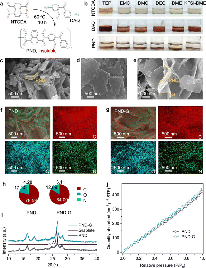
Here, two soluble high-capacity small molecules (NTCDA and DAQ) were polymerized and obtained an organic material (PND, Fig. 1a), which is insoluble in the common solvents (such as triethyl phosphate, TEP; ethyl methyl carbonate, EMC; dimethyl carbonate, DMC; diethyl carbonate, DEC; and 1,2-dimethoxyethane, DME) and 5 M KFSI-DME (5 M potassium bis(fluorosulfonyl)imide in DME) electrolyte at room temperature (Fig. 1b). In order to enhance the conductivity, a 5 wt% graphite (G) sheets were also introduced during the synthesis process and named this product as PND-G. The graphite sheets were successfully grafted to the PND sheets, as observed by scanning electron microscopy (SEM). Moreover, the in situ electrochemical impedance spectroscopy (EIS) also indicating that the introduction of graphite sheets can decrease the impedance. To fully investigate the as-prepared materials, we also used X-ray diffraction (XRD) analysis, cyclic voltammetry (CV) test, and Brunner–Emmett–Teller (BET) measurement. Specifically, when using a 5 M KFSI-DME electrolyte, the K‖PND-G half-cell exhibited a good stability over 1500 cycles, indicating that our design strategy is effective. Also, the full-cell assembled with the PND-G cathode and graphite anode exhibited a stability over 50 cycles.
2. Experimental
2.1 Materials synthesis
The PND-based materials were synthesized by a simple solvothermal method. Specifically, NTCDA (4 mmol) and DAQ (4 mmol) were completely dissolved into N-methylpyrrolidone (NMP, 40 ml) by ultrasound dispersion for half an hour. The mixture was transferred to a round bottomed flask and then experienced 10 hours of reflux at 160 °C under stirring. A solid mixture was obtained by centrifugation, washed with NMP and anhydrous ethanol, and dried under 80 °C. The final PND product was obtained by processing at 250 °C for 8 hours in an argon atmosphere. To prepare the PND-G product, 5 wt% (calculated based on the final PND mass) graphite sheets were added to the solution during the ultrasonic stage, other operations are consistent with the preparation of pure PND materials.2.2 Preparation of the electrodes
The active material, Ketjen Black, and polyvinylidene fluoride (PVDF) (7![[thin space (1/6-em)]](https://www.rsc.org/images/entities/char_2009.gif) :
:![[thin space (1/6-em)]](https://www.rsc.org/images/entities/char_2009.gif) 2
2![[thin space (1/6-em)]](https://www.rsc.org/images/entities/char_2009.gif) :
:![[thin space (1/6-em)]](https://www.rsc.org/images/entities/char_2009.gif) 1; mass ratio) were mixed in NMP. Then the mixture was cast on an Al foil with an average active material loading was about 0.9–1.2 mg cm−2. After that, the electrodes were dried at 65 °C for overnight in vacuum. The graphite electrode was also prepared with the mass ratio of 8
1; mass ratio) were mixed in NMP. Then the mixture was cast on an Al foil with an average active material loading was about 0.9–1.2 mg cm−2. After that, the electrodes were dried at 65 °C for overnight in vacuum. The graphite electrode was also prepared with the mass ratio of 8![[thin space (1/6-em)]](https://www.rsc.org/images/entities/char_2009.gif) :
:![[thin space (1/6-em)]](https://www.rsc.org/images/entities/char_2009.gif) 1
1![[thin space (1/6-em)]](https://www.rsc.org/images/entities/char_2009.gif) :
:![[thin space (1/6-em)]](https://www.rsc.org/images/entities/char_2009.gif) 1.
1.
2.3 Characterization of the materials
X-ray diffraction (XRD) measurements were performed on a Bruker D8 ADVANCE diffractometer. The samples were checked by scanning electron microscopy (SEM, S-4800 instrument). The Brunner–Emmett–Teller (BET) measurement was tested by Quabrasorb SI-3MP.2.4 Electrochemical measurements
Electrochemical measurements were performed at room temperature. The half-cells were assembled with working electrode, K foil, electrolyte (ca. 80 microliter), and glass fiber. 5 M potassium bis(fluorosulfonyl)imide in 1,2-dimethoxyethane (5 M KFSI-DME) solution was used as the electrolyte. In this work, “M” stands for mole of salt dissolved in a liter of solvent (not the electrolyte solution). To fabricate the full cells, PND-G cathode and graphite anode were all pre-cycled for 10 cycles. All the cells were aged at room temperature for overnight before the next test. The as-prepared cells were performed on a LAND BTS battery testing system at room temperature. Electrochemical workstation was used to record the cyclic voltammetry (CV) profiles and in situ electrochemical impedance spectroscopy (EIS).3. Results and discussion
As depicted in the Experimental Section, we not only prepared the pure PND material from NTCDA and DAQ via a simple one-step solvothermal method, but also introduced a 5% mass fraction carbon matrixes during the synthesis process to obtain PND-G material. The introduction of carbon matrixes may facilitate sufficient infiltration of electrolyte and increase the conductivity.27,28The morphologies of two samples were firstly investigated by SEM. As shown in Fig. 1c, clearly, the pure PND materials exhibited sheet like structures with varying thicknesses and are stacked on top of each other, with gaps in the middle that can be used to adsorb electrolytes. For the PND-G materials, it is interesting to observe that on the same “S” shaped sheet, the upper part is made of thick PND material, while the lower part is made of ultra-thin graphite sheet (Fig. 1d and e). The graphite sheets may serve as flexible matrix connecting bridges here, alleviating the volume changes caused by electrochemical reactions between the PND and PND.28 Furthermore, the PND materials wrapped in graphite sheets can be observed, which can increase electrode conductivity and reduce impedance. Further, elemental mapping detection was used to analyse the components. Fig. 1f and g depicted the typical morphology and the corresponding element maps. We can observe a uniform distribution of C, N, and O elements on both the PND and PND-G samples. Moreover, in terms of element content (Fig. 1h), there are differences among these three elements in both the PND and PND-G samples. Specifically, compared to pure PND materials, the carbon content in PND-G materials increases, while the content of the other two elements decreases due to the addition of graphite.
The XRD patterns in Fig. 1i reveal that the peak positions of PND-G match well with pure PND, indicating that the introduction of carbon matrix will not lead to significant peak shifts. The strong peak of PND-G material around 26.5 comes from the superposition of the PND and graphite.29 Considering that the PND-G material in this work serves as the cathode for PIBs (voltage range 1.0–3.5 V), and the reaction between potassium ions and graphite occurs below 0.5 V,29 the introduced graphite may not cause additional electrochemical redox reactions. Also, the BET test was conducted and the corresponding results were shown in Fig. 1j. Compared with the PND material, the introduction of 5 wt% graphite leads to a slight increase in BET surface area. Specifically, the maximal quantity adsorbed value of PND material is 424.23 cm3 g−1, while the maximal quantity adsorbed value of PND-G material is 442.21 cm3 g−1, indicating that the latter has a larger BET surface area to adsorb gas. This characteristic will also facilitate the adsorption of electrolyte for rapid ion transport.
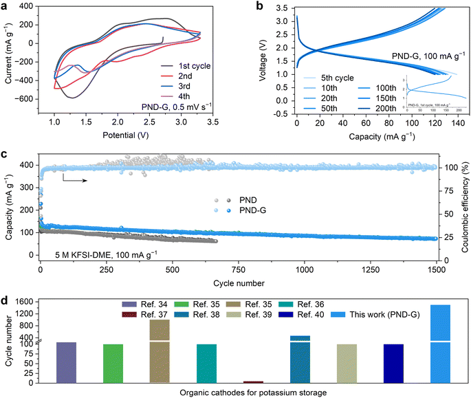
To evaluate the electrochemical properties of the PND and PND-G cathodes, the two materials were assembled in coin cells with metallic potassium as counter and reference electrode. The initial four CV profiles of K‖PND-G cell at a scanning speed of 0.5 mV s−1 were illustrated in Fig. 2a. The electrode exhibits the intense anodic/cathodic peaks, which correspond to the redox reactions of the potassium storage sites (Fig. 1a).7,28–30 Fig. 2b exhibited the charge–discharge profiles of K‖PND-G cell within the voltage range of 1.0 to 3.5 V (two electron transfer) at a current density 100 mA g−1. The difference in the charge–discharge profiles between the 5th to 200th cycles is small, indicating the high electrochemical repeatability of PND-G cathode. Moreover, the similar capacity of each charge and discharge also indicated that this electrochemical reaction is reversible. And the stable Coulombic efficiency of K‖PND-G cell in Fig. 2c also support its good reversibility. It is worth noting that the K‖PND-G cell achieved a stability of 1500 cycles under a constant-current of 100 mA g−1 with good Coulombic efficiency near 99.9% (Fig. 2c). For comparison, the capacity of the PND cathode is lower than that of PND-G in the same condition. Moreover, after 250 cycles, the Coulombic efficiency of pure PND exceeds 100%, which may be due to limited ion transport during charging processes, resulting in a poor charging phenomenon where the charging capacity exceeds the discharge capacity.5,31,32 This phenomenon is harmful and irreversible, often accompanied by a rapid decrease in capacity.33 These results mean that our strategy has a positive effect on solving the problems of rapid capacity degradation and poor Coulombic efficiency of conventional organic electrodes, which proves the importance of constructing insoluble and high conductivity electrodes. It is worth noting that the long-term cycling performance of PND-G cathode has certain advantages compared to other works34–40 (Fig. 2d).
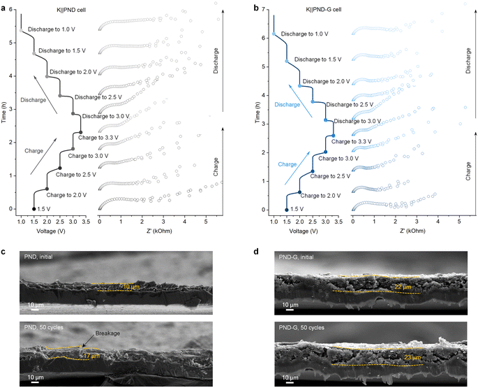
In order to further understand the charge transfer kinetics of the PND-based cathodes, in situ EIS of the K‖PND and K‖PND-G cells were performed (Fig. 3a and b). It is known that the formation of electrode–electrolyte interface (EEI) during the initial discharge cycle will cause a significant change in resistance.7,28,29 Therefore, the in situ EIS measurements were performed using the first charge and the following discharge process. Notably, the K‖PND cell exhibited higher resistances than that of the K‖PND-G cell. These findings indicate that PND-G inherently has low impedance, which facilitates ion transport and improves the original conduction defects of organic materials.
We compared the thicknesses of the PND electrode (Fig. 3c) and the PND-G electrode (Fig. 3d) in the initial and depotassiation states after 50 cycles at the current density of 100 mA g−1. For PND electrode, the initial electrode thickness is 10 μm, and after 50 cycles, its thickness expanded to 17 μm. And obvious breakage can be seen on the electrode after cycling. This change originates from the electrochemical reaction between the PND electrode and potassium ions. On the contrary, with the help of graphite, the thickness of the PND-G electrode changed from the initial 22 μm to 23 μm, and its volume change rate is much smaller than that of the PND electrode. This is because the grafted graphite on the PND-G electrode can buffer the volume change of PND sheet during charge and discharge processes.
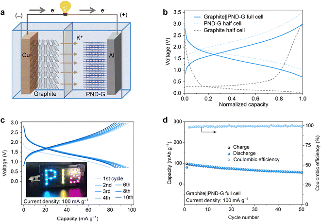
Furthermore, full cells were assembled using PND-G as the cathode, graphite as the anode, and 5 M KFSI-DME as the electrolyte (Fig. 4a). The graphite anode was pre-potassiated by running for 10 cycles and then discharged to 0.01 V, the cathodes were also pre-cycled for 10 cycles, and the capacity was calculated according to the mass of the cathode. As shown in Fig. 4b and c, the fabricated potassium-based graphite‖PND-G full cell has a typical charge–discharge profile similar to that of the K‖PND-G cell. Moreover, we found that two graphite‖PND-G full cells could power a LED light panel with “PIB” on it and light it up (Fig. 4c). The graphite‖PND-G full cell exhibited a cycling stability of 50 cycles at the current density of 100 mA g−1 (as shown in Fig. 4d). These properties indicate that the PND-G cathode proposed in this work has certain guidance, and may helpful to addressing the solubility and poor conductivity issues of organic electrode materials.
4. Conclusions
An insoluble and high conductive PND-G organic electrodes was developed by a facilely synthesize method. The as-prepared PND-G cathode realized a cycling life of over 1500 cycles with stable Coulombic efficiency, the K‖PND-G cell also possesses a low impedance, and the graphite‖PND-G full cell exhibited a cycling stability of 50 cycles. This study may provide significant insights for further exploring high-performance organic cathode materials to address their solubility and poor conductivity issues.Author contributions
B. L. and L. F. developed the concept. All the authors discussed and co-wrote the manuscript.Conflicts of interest
There are no conflicts to declare.Acknowledgements
X. S. and X. Y. contributed equally to this work. This work was financially supported by the National Natural Science Foundation of China (No. U20A20247 and 51922038).Notes and references
- L. Mauler, F. Duffner, W. G. Zeier and J. Leker, Energy Environ. Sci., 2021, 14, 4712–4739 RSC.
- J. C. Pramudita, D. Sehrawat, D. Goonetilleke and N. Sharma, Adv. Energy Mater., 2017, 7, 1602911 CrossRef.
- M. M. Uddin, M. H. Kabir, M. A. Ali, M. M. Hossain, M. U. Khandaker, S. Mandal, A. Arifutzzaman and D. Jana, RSC Adv., 2023, 13, 33336–33375 RSC.
- X. Yi, H. Fu, A. M. Rao, Y. Zhang, J. Zhou, C. Wang and B. Lu, Nat. Sustain., 2024, 7, 326–337 CrossRef.
- Y. Liang and Y. Yao, Joule, 2018, 2, 1690–1706 CrossRef CAS.
- Q. Pan, Y. Zheng, Z. Tong, L. Shi and Y. Tang, Angew. Chem., Int. Ed., 2021, 60, 11835–11840 CrossRef CAS PubMed.
- J. Peng, X. Yi, L. Fan, J. Zhou and B. Lu, Energy Lab., 2023, 1, 220014 Search PubMed.
- L. Tao, J. Zhao, J. Chen, C. Ou, W. Lv and S. Zhong, Nanoscale Adv., 2021, 3, 3199–3215 RSC.
- B. Tian, J. Zheng, C. Zhao, C. Liu, C. Su, W. Tang, X. Li and G.-H. Ning, J. Mater. Chem. A, 2019, 7, 9997–10003 RSC.
- Y. Katsuyama, H. Kobayashi, K. Iwase, Y. Gambe and I. Honma, Adv. Sci., 2022, 9, 2200187 CrossRef CAS PubMed.
- Y. Hu, Q. Yu, W. Tang, M. Cheng, X. Wang, S. Liu, J. Gao, M. Wang, M. Xiong, J. Hu, C. Liu, T. Zou and C. Fan, Energy Storage Mater., 2021, 41, 738–747 CrossRef.
- T. Shi, G. Li, Y. Han, Y. Gao, F. Wang, Z. Hu, T. Cai, J. Chu and Z. Song, Energy Storage Mater., 2022, 50, 265–273 CrossRef.
- Y. Hu, Y. Gao, L. Fan, Y. Zhang, B. Wang, Z. Qin, J. Zhou and B. Lu, Adv. Energy Mater., 2020, 10, 2002780 CrossRef CAS.
- Z. Li, J. Tan, Y. Wang, C. Gao, Y. Wang, M. Ye and J. Shen, Energy Environ. Sci., 2023, 16, 2398–2431 RSC.
- S. Bai, B. Kim, C. Kim, O. Tamwattana, H. Park, J. Kim, D. Lee and K. Kang, Nat. Nanotechnol., 2021, 16, 77–84 CrossRef CAS PubMed.
- X. Yi, A. M. Rao, J. Zhou and B. Lu, Nano-Micro Lett., 2023, 15, 200 CrossRef CAS PubMed.
- Y. He, Y. Qiao, Z. Chang and H. Zhou, Energy Environ. Sci., 2019, 12, 2327–2344 RSC.
- X. Yi, Y. Feng, A. M. Rao, J. Zhou, C. Wang and B. Lu, Adv. Mater., 2023, 35, 2302280 CrossRef CAS PubMed.
- L. Fan, R. Ma, J. Wang, H. Yang and B. Lu, Adv. Mater., 2018, 30, 1805486 CrossRef PubMed.
- X. Liu, Y. Jin, H. Wang, X. Yang, P. Zhang, K. Wang and J. Jiang, Adv. Mater., 2022, 34, 2203605 CrossRef CAS PubMed.
- Z. Yang, J. Liu, Y. Li, G. Zhang, G. Xing and L. Chen, Angew. Chem., Int. Ed., 2021, 60, 20754–20759 CrossRef CAS PubMed.
- Y. Yang, P. Zhang, L. Hao, P. Cheng, Y. Chen and Z. Zhang, Angew. Chem., Int. Ed., 2021, 60, 21838–21845 CrossRef CAS PubMed.
- H. Zhang, H. Wang, S.-a. Cao, T. Li and F. Xu, Mater. Lett., 2020, 268, 127596 CrossRef CAS.
- B.-C. Liao, B.-H. Jian, M.-J. Wu and J.-T. Lee, ACS Appl. Energy Mater., 2023, 6, 8581–8589 CrossRef CAS.
- K. Pongpanyanate, S. Roddecha, C. Piyanirund, T. Phraewphiphat and P. Hasin, RSC Adv., 2024, 14, 2354–2368 RSC.
- Y. Hu, H. Ding, Y. Bai, Z. Liu, S. Chen, Y. Wu, X. Yu, L. Fan and B. Lu, ACS Appl. Mater. Interfaces, 2019, 11, 42078–42085 CrossRef CAS PubMed.
- S. Wang, W. Deng, Z. Geng, P. Li, N. Hu, L. Zhu, W. Sun and C. M. Li, Battery Energy, 2023, 2, 20220050 CrossRef CAS.
- X. Yi, J. Ge, J. Zhou, J. Zhou and B. Lu, Sci. China: Chem., 2021, 64, 238–244 CrossRef CAS.
- L. Fan, H. Xie, Y. Hu, Z. Caixiang, A. M. Rao, J. Zhou and B. Lu, Energy Environ. Sci., 2023, 16, 305–315 RSC.
- Y. Yamada, J. Wang, S. Ko, E. Watanabe and A. Yamada, Nat. Energy, 2019, 4, 269–280 CrossRef CAS.
- W. L. Jorgensen and J. Tirado-Rives, Proc. Natl. Acad. Sci. U. S. A., 2005, 102, 6665–6670 CrossRef CAS PubMed.
- T. Zhu, H. Sternlicht, Y. Ha, C. Fang, D. Liu, B. H. Savitzky, X. Zhao, Y. Lu, Y. Fu, C. Ophus, C. Zhu, W. Yang, A. M. Minor and G. Liu, Nat. Energy, 2023, 8, 129–137 CrossRef CAS.
- M. A. T. Marple, B. G. Aitken, S. Kim and S. Sen, Chem. Mater., 2017, 29, 8704–8710 CrossRef CAS.
- J. Ge, L. Fan, A. M. Rao, J. Zhou and B. Lu, Nat. Sustain., 2022, 5, 225–234 CrossRef.
- M. Xiong, W. Tang, B. Cao, C. Yang and C. Fan, J. Mater. Chem. A, 2019, 7, 20127–20131 RSC.
- Y. Hu, W. Tang, Q. Yu, X. Wang, W. Liu, J. Hu and C. Fan, Adv. Funct. Mater., 2020, 30, 2000675 CrossRef CAS.
- Z. Zhang, Y. Zhu, M. Yu, Y. Jiao and Y. Huang, Nat. Commun., 2022, 13, 6489 CrossRef CAS PubMed.
- J. Ge, X. Yi, L. Fan and B. Lu, J. Energy Chem., 2021, 57, 28–33 CrossRef CAS.
- Y. Bai, W. Fu, W. Chen, Z. Chen, X. Pan, X. Lv, J. Wu and X. Pan, J. Mater. Chem. A, 2019, 7, 24454–24461 RSC.
- R. R. Kapaev, A. G. Scherbakov, A. F. Shestakov, K. J. Stevenson and P. A. Troshin, ACS Appl. Energy Mater., 2021, 4, 4465–4472 CrossRef CAS.
Footnote |
| † These authors contributed equally to this work. |
| This journal is © The Royal Society of Chemistry 2024 |


