 Open Access Article
Carbon nitride/polyimide porous film via an NIPS method with advanced dielectric and hydrophobicity properties
Wen Li,
Kejing Li,
Weizhen Li *,
Wenjun Gan
 and
Shiqiang Song
 *
*
Department of Macromolecular Materials and Engineering, School of Chemistry and Chemical Engineering, Shanghai University of Engineering Science, 201620, Shanghai, China. E-mail: liweizhen@sues.edu.cn; polymer_song@hotmail.com
First published on 13th May 2024
Abstract
Herein, an ultra-low dielectric porous polyimide (PPI) composite film was fabricated by non-solvent induced phase separation (NIPS). High-performance carbon nitride nanosheets grafted by heptadecafluoro-1,1,2,2-tetradecyl-trimethoxysilane (CNNF) were incorporated into the PPI film to enhance thermomechanical and hydrophobic properties. The effects of non-solvent and filler content on the porous morphology, dielectric properties, hydrophobicity and thermomechanical properties of films were investigated. The porous morphology of the CNNF/PPI film changed from the coexistence of pipe-like and spongy structure via H2O, to a tightly-stacked porous structure via MeOH as non-solvent. The dielectric constants ε′ of 0.5 wt%-CNNF/PPI(H2O) and 0.5 wt%-CNNF/PPI(MeOH) were 1.56 and 1.69 at 1 MHz, respectively, which were ∼50% lower than that of the original PI film (ε′ = 3.33). With the introduction of CNNF, the water contact angle (WCA) of CNNF/PPI(H2O) increased from 66° to 107° and that of CNNF/PPI(MeOH) increased from 92° to 120°. Simultaneously, the storage modulus E′ of 2 wt%-CNNF/PPI(MeOH) reached its highest value of ∼881 MPa, which was ∼350 MPa higher than that of PPI(MeOH), together with an enhancement in Tg. This method confirmed a promising prospect for the utilization of porous PI substrates in integrated circuits and microelectronic devices.
1. Introduction
With the rapid growth of the 5G/6G era and miniaturization of electronic devices, materials with an ultra-low dielectric constant have become increasingly in demand in recent years. These devices are the most cost-effective way to minimize crosstalk, solve signal transmission delay, and promote the development of high-frequency devices and communication modules.1–4High-performance insulating polymer materials, such as polyimide (PI), have attracted wide attention in the microelectronics industry, due to its outstanding mechanical properties, high breakdown strength, excellent thermal stability and low moisture absorption.5–8 Nevertheless, the relatively high dielectric constant of PI (ε′ ∼3.3–3.5) restricts its further application as a dielectric layer material in “high-speed” integrated circuits. Thus, efforts to develop PI substrates with an ultra-low dielectric constant have become the focus of attention in the field of integrated circuits and micro-devices over the past few years.9–12
In general, there are two principles for lowering the dielectric constant: reduction of the dipole strength and reduction of the number of dipoles.13 Based on previous research, there are three efficient ways to achieve PI films with a low dielectric constant or dielectric loss: design of the chemical structure by adding groups with large free volume or strongly polar fluorine elements;14 the introduction of an air-porous structure into the polymer matrix since air is the substance with the lowest dielectric constant of 1.0;8,15 blending with fluorine-containing fillers, such as fluorographene16–19 or fluorinated ethylene propylene (FEP) nanoparticles.20,21 The design of the chemical structure is usually very costly and causes a decrease in the glass transition temperature (Tg) of PI. The latter two ways are currently identified as being more practical approaches to obtain PI substrates with a low dielectric constant. Chen et al.22 proposed a new method for synthesizing fluorine-containing graphene oxide, which improved the dielectric property (ε′ = 2.34) and mechanical properties of PI composites.
Porous polymer films have been prepared by various methods, such as the use of foaming agents, the pyrolysis foaming method, chemical dissolution of block domains of the copolymer, and the non-solvent induced phase separation (NIPS) method.23–26 As a flexible method, NIPS has been commonly utilized to fabricate various porous polymer films. Khim et al.27 fabricated a hierarchically porous PI film by NIPS and grafted PI onto amino-functionalized mesoporous silica (AMS) to further regulate the thermal stability and dielectric constant (ε′ = 1.84). The interactions among polymer, solvent, and non-solvent play an important role in controlling the diffusive and exchange status, leading to changeable porous morphologies. However, the porous structure might inevitably be detrimental to hydrophobicity, mechanical properties and thermal stability. Thus, finding a balance between multiple properties is a challenge for the fabrication of porous PI films.
In this study, a facile NIPS method was employed to fabricate porous precursor films with interconnected pores using different solvents as a coagulation bath, followed by thermal imidization. Two-dimensional graphite nitride carbon (g-C3N4), as a high-performance electrical-insulated filler, was used to reinforce the porous structure and retain the thermomechanical properties of the polymer matrix.28–31 Additionally, g-C3N4 was exfoliated on the basis of a surfactant-assisted liquid exfoliation method32 and further grafted with heptadecafluoro-1,1,2,2-tetradecyl-trimethoxysilane (FAS) to improve the hydrophobicity property. This would lead to reliable ultra-low dielectric performance under extreme environmental conditions.
2. Experimental
2.1 Materials
g-C3N4 powder was purchased from XFNANO Materials Tech Co., Ltd, China. 4,4′-oxydianiline (ODA) and 4,4′-oxydiphthalic anhydride (ODPA) were provided by Shanghai Synthetic Resin Co., Ltd, China. Triammonium phosphate trihydrate ((NH4)3PO4·3H2O), sodium hydroxide (NaOH), 1-methyl-2-pyrrolidone (NMP), ethanol and methanol (MeOH) were supplied by Shanghai Titan Scientific Co., Ltd. FAS was obtained from SHANG FLUORO Tech Co., Ltd, China.2.2 Exfoliation and amino-functionalization of g-C3N4
The exfoliation and amino-functionalization of g-C3N4 nanosheets (CNNS) was carried out by a ball-milling method, which is illustrated in Scheme 1. First, g-C3N4 powder was mixed sufficiently with a mixture of (NH4)3PO4·3H2O and NaOH (where the weight ratio of (NH4)3PO4·3H2O, NaOH, and g-C3N4 was 16.9![[thin space (1/6-em)]](https://www.rsc.org/images/entities/char_2009.gif) :
:![[thin space (1/6-em)]](https://www.rsc.org/images/entities/char_2009.gif) 20
20![[thin space (1/6-em)]](https://www.rsc.org/images/entities/char_2009.gif) :
:![[thin space (1/6-em)]](https://www.rsc.org/images/entities/char_2009.gif) 1). Then, the mixture was ball-milled with zirconia balls under a revolution speed of 640 rpm for 12 h. The mixed powders were then dispersed in deionized water, magnetically stirred for 1 h and further ultrasonicated for 12 h. The obtained products were repeatedly washed with deionized water to get rid of free (NH4)3PO4·3H2O and NaOH until the pH of the supernatant was neutral. The resulting suspension was centrifuged at 3000 rpm three times to remove unexfoliated g-C3N4. Afterward, exfoliated CNNS were collected.
1). Then, the mixture was ball-milled with zirconia balls under a revolution speed of 640 rpm for 12 h. The mixed powders were then dispersed in deionized water, magnetically stirred for 1 h and further ultrasonicated for 12 h. The obtained products were repeatedly washed with deionized water to get rid of free (NH4)3PO4·3H2O and NaOH until the pH of the supernatant was neutral. The resulting suspension was centrifuged at 3000 rpm three times to remove unexfoliated g-C3N4. Afterward, exfoliated CNNS were collected.
2.3 Preparation of FAS-grafted carbon nitride nanosheets (CNNF)
First, 0.2 g of CNNS powder was ultrasonically dissolved in ethanol for 30 min, followed by 0.6 g of FAS and 2 mL of deionized water, then backflowed at 80 °C for 2 h. The obtained product was washed with ethanol several times to remove free FAS. Centrifugation and freeze drying were used to collect resulting CNNF.2.4 Synthesis process of CNNF/polyamic acid
First, a certain amount of CNNF was dispersed in 100 g of NMP. Then, 29.36 mmol of ODA (5.88 g) was dissolved in the above solution and stirred for 30 min under a dry nitrogen atmosphere. Next, 29.40 mmol of ODPA (9.12 g) was added in portions. Then, the solution was kept at 0 °C and stirred vigorously for 6 h. Finally, a homogeneous CNNF/polyamic acid (CNNF/PAA) precursor solution was obtained.2.5 Preparation of CNNF/PI and CNNF/PPI films
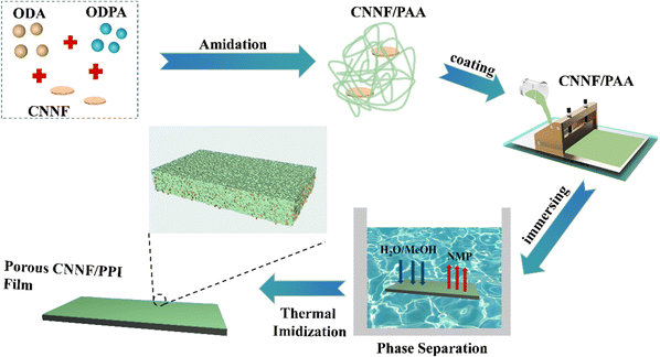
CNNF/PI non-porous film was obtained by a solution-casting process. The CNNF/PAA precursor solution was first caste on a clean glass plate with a scraper to form a CNNF/PAA wet film, followed by drying in a vacuum environment with a stepwise heating procedure. Then, the CNNF/PI non-porous film was obtained by thermal imidization at 200 °C and 300 °C for 1 h each.CNNF/PPI porous film was prepared by the NIPS method, the process of which is illustrated in Scheme 2. First, the CNNF/PAA precursor was uniformly coated on a clean glass plate with a scraper to form a CNNF/PAA wet film. Then, the wet film was soaked in deionized water (H2O) or MeOH as a coagulation bath for sufficient exchange to form a porous CNNF/PAA film. The porous film was peeled off from the glass plate and dried in a vacuum environment with a stepwise heating procedure (thermal imidization at 200 °C and 300 °C for 1 h each). Herein, PPI porous films generated by H2O or MeOH as the coagulation bath are denoted CNNF/PPI(H2O) and CNNF/PPI(MeOH).
2.6 Characterization
Fourier transform infrared spectroscopy (FTIR, Thermo Fisher, Nicolet AVATAR 370, USA) was employed to characterize the modification of fillers. X-ray diffraction (XRD, Bruker D2 PHASER, Germany) was used to characterize the crystallization peaks of original g-C3N4 and exfoliated CNNS. X-ray photoelectron spectroscopy (XPS, Thermo Fisher, ESCALAB Xi+, USA) was performed to qualitatively characterize the bonding energy of the surface of CNNF. The morphologies of the top and cross-sectional surfaces of CNNF/PI composite films were observed by scanning electron microscopy (SEM, Hitachi S-3400, Japan). Porous films were fractured in liquid nitrogen and sputter-coated with gold. The dielectric properties were measured by an impedance analyzer (Julang Technology, TZDM-200-300, China) within a frequency range of 50–106 Hz at normal temperature. Contact angle measurement (JC2000D, China) was used to evaluate the hydrophobic properties. The dynamic mechanical properties were measured by dynamic mechanical analysis (DMA, TA Q800, USA) in film tension mode with a heating rate of 5 °C min−1.3. Results and discussion
3.1 Characterization of CNNS and CNNF
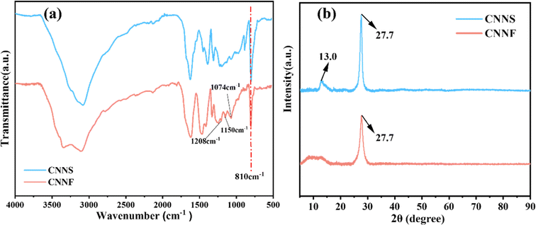
Exfoliated CNNS and CNNF were characterized by FTIR, and the results are shown in Fig. 1a. The band at 810 cm−1 corresponds to the out-of-plane bending of triazine molecules, whereas the peaks at 1626 cm−1 and 1397 cm−1 are ascribed to the tensile vibration peak of aromatic C–N. Furthermore, the peaks at 1313 cm−1 and 1230 cm−1 are related to C–N (–C)–C or C–NH–C. Besides, the range from 3000 cm−1 to 3500 cm−1 corresponds to the stretching vibration peaks of –NH2 and –OH.28The presence of these characteristic peaks indicates that the chemical structure of CNNS remains consistent after the grafting of FAS. It is noteworthy that three new characteristic peaks appear in the spectrum of CNNF. The peaks at 1150 cm−1 and 1208 cm−1 are attributed to the stretching vibration band of covalent C–F. The peak at 1074 cm−1 originates from the stretching vibration peak of Si–O–C. The above peaks represent the unique chemical structures of FAS and prove the successful grafting of FAS on the surface of CNNS.
XRD patterns of CNNS and CNNF samples are given in Fig. 1b. A strong peak at 27.7° is indexed as the (002) crystal face of a graphite-like layer stack structure, representing the accumulation of conjugated aromatic rings. Compared with CNNS, the diffraction peak intensity of CNNF at 27.7° is further reduced, indicating a reduction in thickness of the interplanar stacking. The peak at 13.0° is indexed as the (100) crystal face of the in-plane repeating structural unit of graphite, which changes from a sharp peak to a wide and steamed dumpling peak, due to the overlapping of FAS.33
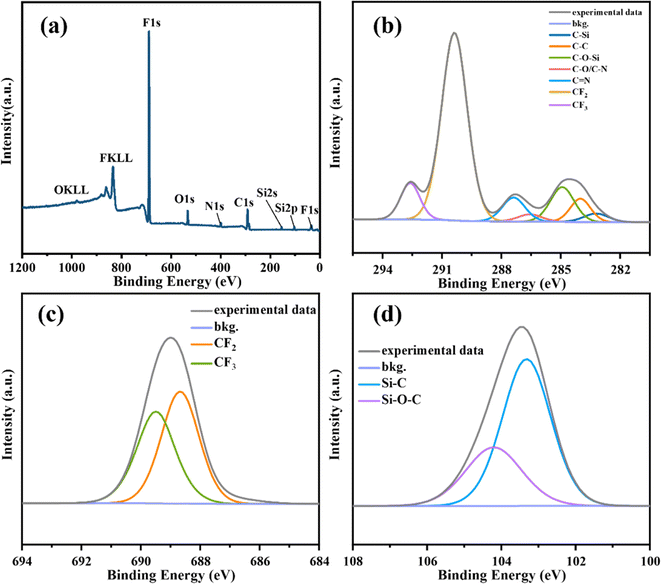
The chemical structure of the CNNF surface was probed by XPS, and the results are shown in Fig. 2. As shown in Fig. 2b, the peaks of C–Si (283.2 eV), C–C (284.0 eV), C–O–Si (284.9 eV), C–O/C–N (286.6 eV), C![[double bond, length as m-dash]](https://www.rsc.org/images/entities/char_e001.gif) N (287.4 eV), CF2 (290.4 eV) and CF3 (292.6 eV) can clearly be observed in the C1s spectrum. Fig. 2c shows the detailed F1s XPS spectrum at around 690 eV, which can be fitted into two peaks corresponding to –CF3 (689.49 eV) and –CF2 (688.68 eV), respectively. This confirms FAS grafted on the surface of carbon nitride. Furthermore, two peaks at 103.1 eV and 104.4 eV in the Si2p spectrum (Fig. 2d) are assigned to Si–C and Si–O–C, respectively. To sum up, the surface of CNNS was actually grafted by FAS.
N (287.4 eV), CF2 (290.4 eV) and CF3 (292.6 eV) can clearly be observed in the C1s spectrum. Fig. 2c shows the detailed F1s XPS spectrum at around 690 eV, which can be fitted into two peaks corresponding to –CF3 (689.49 eV) and –CF2 (688.68 eV), respectively. This confirms FAS grafted on the surface of carbon nitride. Furthermore, two peaks at 103.1 eV and 104.4 eV in the Si2p spectrum (Fig. 2d) are assigned to Si–C and Si–O–C, respectively. To sum up, the surface of CNNS was actually grafted by FAS.
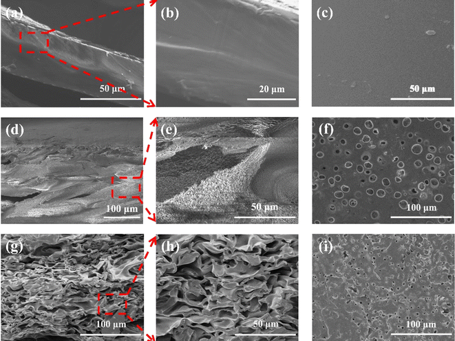
3.2 Morphology and structure of the composite films
SEM images of the cross-section and top surface of the PI and PPI films are illustrated in Fig. 3. As can be seen from Fig. 3a–c, the cross-section and top surface of PI film are uniform and smooth. In Fig. 3d–i, the cross-section and top surface of PPI(H2O) and PPI(MeOH) films via NIPS show a porous structure with different characters. The microstructures of the PPI films induced by two coagulation baths apparently differ from each other. The cross-section of the PPI(H2O) film displays the coexistence of large pipe-like pores (average size >100 μm) throughout the vertical cross-section and a sponge-like micropore structure (average size ∼1–3 μm) on the shell of the pipe, shown magnified in Fig. 3e. Nevertheless, a tightly-stacked porous structure (average size ∼10–30 μm) is shown in the cross-section of the PPI(MeOH) film, shown magnified in Fig. 3h. The results indicate that the porous morphology depends on the affinity between solvent (NMP) and non-solvent (coagulation bath), which leads to different diffusion rates of liquid–liquid demixing during phase separation. The large pipe-like porous structure of PPI(H2O) film is induced by an instantaneous phase separation, which occurs during the initial stage due to the strong mutual affinity between H2O and NMP,34 whereas tightly-packed pores in the PPI(MeOH) film are attributed to the relatively low diffusion rate between MeOH and NMP in the PAA matrix. In other words, the stronger interaction between solvent (NMP) and non-solvent (H2O) leads to a higher diffusion rate and promotes the aggregation of PAA molecules, which induces rapid phase separation and constructs the large pipe-like pores. Nevertheless, the relatively slow diffusion rate of non-solvent (MeOH) provides the tightly-stacked porous structure of PAA.The morphologies of the cross-sections of porous CNNF/PPI films prepared via H2O and MeOH as coagulation baths are shown in Fig. 4 and 5, respectively. The entire porous morphology of the large pipe-like pores in the PPI(H2O) film remains consistent with the loading of CNNF, whereas the stacked pores of the CNNF/PPI(MeOH) film grow slightly larger with the increase in CNNF content. The porous morphologies with distinct structures are consistent with the porosity of the CNNF/PPI films produced via the two coagulation baths. The porosity of 0.5, 1.0, and 2.0 wt%-CNNF/PPI(H2O) films was measured to be 64.8%, 63.1%, and 61.6%, respectively, while the porosity of 0.5, 1.0, and 2.0 wt%-CNNF/PPI(MeOH) films was found to be 22.5%, 24.8%, and 29.0%, respectively. The porosity of CNNF/PPI(H2O) is much higher than that of CNNF/PPI(MeOH).
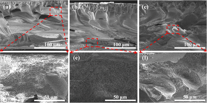 | ||
| Fig. 4 SEM images of cross-section of (a–c) CNNF/PPI(H2O) films with CNNF contents of 0.5, 2.0, and 5.0 wt%; (d–f) image magnification of (a–c). | ||
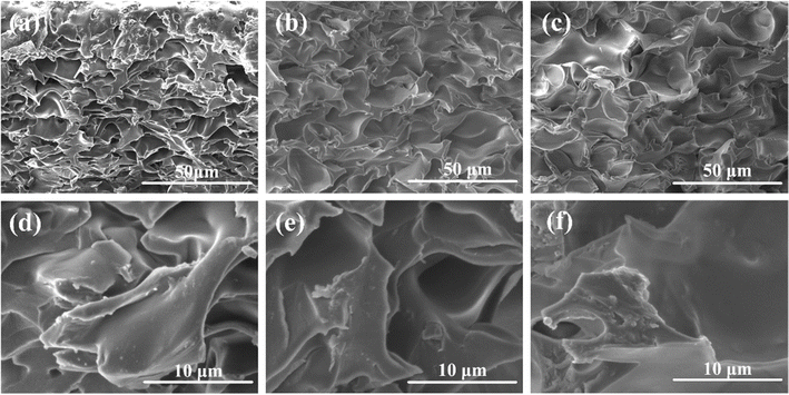 | ||
| Fig. 5 SEM images of cross-section of (a–c) CNNF/PPI(MeOH) films with CNNF contents of 0.5, 2.0, and 5.0 wt%; (d–f) image magnification of (a–c). | ||
In addition, the scattering dispersion of CNNF on the shell of the stacked pores in CNNF/PPI(MeOH) can apparently be investigated, as seen in Fig. 5d–f. Based on the variation in porosity of CNNF/PPI(MeOH), it is suggested that CNNF nanofillers may reinforce the micro-porous structure. The agglomeration of nanofillers becomes apparent when loaded with 2.0–5.0 wt% CNNF content (Fig. 5e and f), which induces an enhancement in interfacial polarization. This is the main reason for the increase in dielectric constant of the polymer/fillers composite. To achieve optimal properties, the PPI films with 0.5–2.0 wt% CNNF were selected to test their dielectric properties.
3.3 Dielectric properties of CNNF/PI and CNNF/PPI films
The dielectric properties of the CNNF/PI and CNNF/PPI films were evaluated in the frequency range 50–106 Hz at room temperature (Fig. 6 and 7). Fig. 6a, 7a and 7c demonstrate the dielectric constants ε′ of composite films with varying filler content. All the PPI films possess remarkably lower dielectric constants ε′ and dielectric loss ε′′ compared to the PI films, with ε′ ranging from 1.56 to 2.50 and ε′′ ranging from 0.0005 to 0.013 at 1 MHz. The 0.5 wt%-CNNF/PPI films exhibit the lowest dielectric constants of 1.56 and 1.69 at 1 MHz via H2O and MeOH as coagulation baths, respectively, which are ∼50% lower than that of the original PI film (ε′ = 3.33) and are generally independent of frequency over the frequency sweep. The apparent reduction in dielectric constant is due to the incorporation of a porous structure and FAS-grafted fillers into the PI matrix. The lowest dielectric constant of the PPI film occurs with 0.5 wt% CNNF content, which means that the overall porous structure (porosity and pore size distribution) and distribution of CNNF are optimum. When the CNNF content increases from 0.5 wt% to 2.0 wt%, the ε′ of CNNF/PPI(H2O) increases from 1.56 to 2.11 and that of CNNF/PPI(MeOH) increases from 1.69 to 2.50. Initially, the well-dispersed 0.5 wt% CNNF fillers interact with polymer chains and restrict the mobility of the molecular dipoles of the PI chains, thereby reducing the overall polarizability of non-porous and porous PI films.18 However, with increasing CNNF content, the interfacial polarization induced by the agglomeration of CNNF results in a less effective hindrance of charge regions and generates dipole mobility. Therefore, the dielectric constants of the PI and PPI films appear to increase with higher filler content. This is in agreement with previous studies.19 Meanwhile, the low dielectric loss ε′′ remains consistent (ε′′ <0.013) with the loading of 0.5–2.0 wt% CNNF, as shown in Fig. 7b and d. The 1 wt%-CNNF/PPI films via H2O and MeOH show an ultra-low dielectric loss of ε′′ <0.001.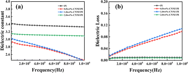 | ||
| Fig. 6 Dependence of dielectric properties on the frequency of the PI films (a) dielectric constant and (b) dielectric loss. | ||
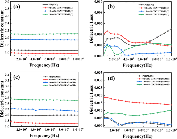 | ||
| Fig. 7 Dependence of dielectric properties on frequency of the PPI films obtained from (a and b) H2O and (c and d) MeOH coagulation bath. | ||
3.4 Hydrophobic property of the CNNF/PPI films
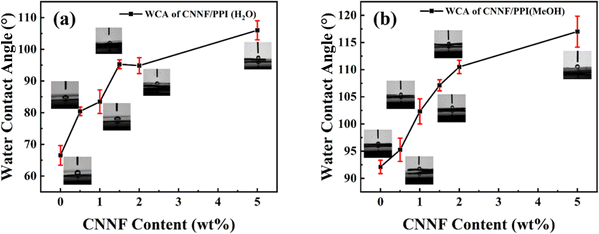
The hydrophobic property of a dielectric film is beneficial for dielectric stability, which can inhibit a sharp rise in dielectric constant due to moisture. The water contact angles (WCA) of CNNF/PPI(H2O) and CNNF/PPI(MeOH) with different CNNF contents were investigated to evaluate the hydrophobic performance of porous films. The results are shown in Fig. 8 and summarized in Table 1. Comparing the porous films via the two coagulation baths, the WCA of CNNF/PPI(H2O) increases from 66° to 107° (Fig. 8a), while that of CNNF/PPI(MeOH) increases from 92° to 120° (Fig. 8b). The better hydrophobicity of CNNF/PPI(MeOH) is attributed to the tightly-stacked micropores, which prevent the passage of moisture. However, the large pipe-like pores throughout the CNNF/PPI(H2O) film might cause quick infiltration of moisture. Besides, with the increase in fluorinated fillers, the enhancement in WCA can be observed in the CNNF/PPI(H2O) and CNNF/PPI(MeOH) films, as shown in Table 1. The improvement in hydrophobicity indicates that the absorption of moisture could be retarded by fluorinated microporous films, thus maintaining the long-term stability of the dielectric property in a humid environment.| PPI(H2O) films | Contact angle | PPI(MeOH) films | Contact angle |
|---|---|---|---|
| PPI(H2O) | 66° | PPI(MeOH) | 92° |
| 0.5-CNNF/PPI(H2O) | 80° | 0.5-CNNF/PPI(MeOH) | 95° |
| 1.0-CNNF/PPI(H2O) | 83° | 1.0-CNNF/PPI(MeOH) | 102° |
| 1.5-CNNF/PPI(H2O) | 95° | 1.5-CNNF/PPI(MeOH) | 107° |
| 2.0-CNNF/PPI(H2O) | 96° | 2.0-CNNF/PPI(MeOH) | 113° |
| 5.0-CNNF/PPI(H2O) | 107° | 5.0-CNNF/PPI(MeOH) | 120° |
3.5 Mechanical property of the PPI films
The dynamic mechanical properties of the CNNF/PPI films are presented in Fig. 9, and the corresponding results are summarized in Table 2. Comparing Fig. 9a with 9c, the storage modulus E′ of CNNF/PPI(MeOH) film is higher than that of the CNNF/PPI(H2O) film. The reason is that the uniformly and tightly-stacked micropores (∼10–30 μm) in the CNNF/PPI(MeOH) film lead to better mechanical properties. While CNNF/PPI(H2O) possesses a large pipe-like structure with an uneven pore size of >100 μm in length, which results in harm to the E′ of the PPI films. Further, it is obvious that the addition of CNNF can remarkably improve the resistance of porous films to elastic deformation for the CNNF/PPI(H2O) and CNNF/PPI(MeOH) films. The strengthening of the PPI films is attributed to the high elastic modulus of CNNF nanosheets. However, the storage modulus E′ increases with the continuous loading of CNNF content up to 2.0 wt%. The E′ of PPI(MeOH) drops from 881 to 573 MPa with an increase in loading from 2 wt% to 5 wt% CNNF. This can be explained by the excessive CNNF aggregation leading to poor interfacial compatibility between nanofillers and the PI matrix, which causes stress defects and mechanical damage.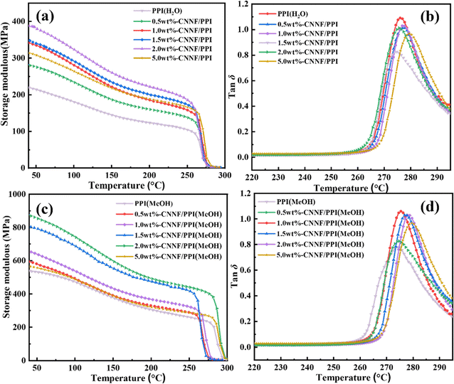 | ||
Fig. 9 Storage modulus E′ and tan![[thin space (1/6-em)]](https://www.rsc.org/images/entities/char_2009.gif) δ versus T of the (a and b) CNNF/PPI(H2O) films and (c and d) CNNF/PPI(MeOH) films. δ versus T of the (a and b) CNNF/PPI(H2O) films and (c and d) CNNF/PPI(MeOH) films. | ||
| PPI films | E′ at 30 °C/MPa | Tg/°C |
|---|---|---|
| PPI(H2O) | 225 | 275 |
| 0.5-CNNF/PPI(H2O) | 281 | 276 |
| 1.0-CNNF/PPI(H2O) | 348 | 276 |
| 1.5-CNNF/PPI(H2O) | 353 | 277 |
| 2.0-CNNF/PPI(H2O) | 389 | 278 |
| 5.0-CNNF/PPI(H2O) | 324 | 280 |
| PPI(MeOH) | 537 | 274 |
| 0.5-CNNF/PPI(MeOH) | 609 | 275 |
| 1.0-CNNF/PPI(MeOH) | 676 | 275 |
| 1.5-CNNF/PPI(MeOH) | 775 | 277 |
| 2.0-CNNF/PPI(MeOH) | 881 | 278 |
| 5.0-CNNF/PPI(MeOH) | 573 | 280 |
The Tg results of CNNF/PPI(H2O) and CNNF/PPI(MeOH) are summarized in Table 2. The original PPI(H2O) and PPI(MeOH) films show Tg at 275 °C and 274 °C, respectively. With the introduction of CNNF, the values of Tg increase by 3–4 °C when the CNNF content reaches 2 wt%. The enhancement in Tg is attributed to strong interactions between the remaining amino groups of the CNNF surface and carbonyl groups of PI, which restricts the movement of the PI molecular chains.
4. Conclusions
A facile NIPS method was proposed to successfully prepare porous PI films with an ultra-low dielectric constant, which contained FAS-grafted g-C3N4 nanosheets. The porous morphology was determined by a non-solvent coagulation bath and the content of nanofillers, which primarily influenced the dielectric property. FAS-grafted g-C3N4 nanosheets were utilized as a high-performance electrically-insulating filler to maintain the hydrophobicity and thermomechanical properties of the PPI porous structure. Compared to the CNNF/PPI(H2O) film, tightly-stacked micropores of the CNNF/PPI(MeOH) film provided better overall performance. The dielectric constants of 0.5 wt%-CNNF/PPI(H2O) and 0.5 wt%-CNNF/PPI(MeOH) were 1.56 and 1.69 at 1 MHz, respectively, which were ∼50% lower than that of the original PI film. Further, the hydrophobicity and thermomechanical properties of the CNNF/PPI(MeOH) film were superior to those of the CNNF/PPI(H2O) film. The storage modulus E′ of 2 wt%-CNNF/PPI(MeOH) was 881 MPa at 30 °C, with a WCA of 113°. Therefore, this optimized porous structure can be considered as potential reliable ultra-low dielectric film for use in microelectronic devices in an extreme environment.Conflicts of interest
The authors declare that they have no known competing financial interests or personal relationships that could have appeared to influence the work reported in this paper.Acknowledgements
This work was supported by National Natural Science Foundation (grant number 52003151). The authors thank to Class III Peak Discipline of Shanghai-Materials Science and Engineering (High-Energy Beam Intelligent Processing and Green Manufacturing).References
- R. Li, X. Yang, J. Li, Y. Shen, L. Zhang, R. Lu, C. Wang, X. Zheng, H. Chen and T. Zhang, Review on polymer composites with high thermal conductivity and low dielectric properties for electronic packaging, Mater. Today Phys., 2022, 22, 100594, DOI:10.1016/j.mtphys.2021.100594.
- F. Liu, Y. Jin, J. Li, W. Jiang and W. Zhao, Improved coefficient thermal expansion and mechanical properties of PTFE composites for high-frequency communication, Compos. Sci. Technol., 2023, 241, 110142, DOI:10.1016/j.compscitech.2023.110142.
- Z. Xie, D. Liu, Y. Xiao, K. Wang, Q. Zhang, K. Wu and Q. Fu, The effect of filler permittivity on the dielectric properties of polymer-based composites, Compos. Sci. Technol., 2022, 222, 109342, DOI:10.1016/j.compscitech.2022.109342.
- X. Yu, M. R. Bhatti, X. Ren, P. Steiner, F. Di Sacco, M. Dong, H. Zhang, D. Papageorgiou, G. Portale, C. Kocabas, C. W. M. Bastiaansen, M. Reece, H. Bilotti and E. Yan, Dielectric polymer composites with ultra-high thermal conductivity and low dielectric loss, Compos. Sci. Technol., 2022, 229, 109695, DOI:10.1016/j.compscitech.2022.109695.
- G. Sun, S. Zhang, Z. Yang, J. Wang, R. Chen, L. Sun, Z. Yang and S. Han, Fabrication and mechanical, electrical properties study of isocyanate-based polyimide films modified by reduced graphene oxide, Prog. Org. Coat., 2020, 143, 105611, DOI:10.1016/j.porgcoat.2020.105611.
- S. Liu, Y. Wang, C. Xiao, M. Jiang, X. Ding, H. Zhang, K. Zheng, L. Chen, X. Tian and X. Zhang, Pea-Pod-like Carbon microspheres encapsulated by graphene-like carbon nitride for enhanced thermal conductivity in polyimide films, ACS Appl. Polym. Mater., 2022, 4(9), 6553–6562, DOI:10.1021/acsapm.2c00929.
- P. Zhang, K. Zhang, X. Chen, S. Dou, J. Zhao and Y. Li, Mechanical, dielectric and thermal properties of polyimide films with sandwich structure, Compos. Struct., 2021, 261, 113305, DOI:10.1016/j.compstruct.2020.113305.
- Y. Li, B. Ma, R. Zhang and X. Luo, Mechanically strong, thermal-insulated, and ultralow dielectric polyimide aerogels with adjustable crosslinking methods, Polymer, 2022, 253, 125035, DOI:10.1016/j.polymer.2022.125035.
- Y. Li, Y. Cao, S. Wu, Y. Ju, X. Zhang, C. Lu and W. Sun, Manipulative pore-formation of polyimide film for tuning the dielectric property via breath figure method, Polymer, 2023, 269, 125731, DOI:10.1016/j.polymer.2023.125731.
- Y. Ma, Z. He, Z. Liao, Y. Han, J. Zhang and M. Zhu, Porous structure contained polyimide film with enhanced dielectric properties upon high temperature, J. Appl. Polym. Sci., 2022, 139(39), e52936, DOI:10.1002/app.52936.
- J. Lee, S. Yoo, D. Kim, Y. H. Kim, S. Park, N. K. Park, Y. So, J. Kim, J. Park, M. J. Ko and J. C. Won, Intrinsic low-dielectric constant and low-dielectric loss aliphatic-aromatic copolyimides: The effect of chemical structure, Mater. Today Commun., 2022, 33, 104479, DOI:10.1016/j.mtcomm.2022.104479.
- Y. Li, G. Sun, Y. Zhou, G. Liu, J. Wang and S. Han, Progress in low dielectric polyimide film - A review, Prog. Org. Coat., 2022, 172, 107103, DOI:10.1016/j.porgcoat.2022.107103.
- Z. Pang, H. Sun, Y. Guo, J. Du, L. Li, Q. Li, J. Yang, J. Zhang, W. Wu and S. Yang, Research Advances of Porous Polyimide-Based Composites with Low Dielectric Constant, Polymers, 2023, 15(16), 3341, DOI:10.3390/polym15163341.
- C. C. Kuo, Y. C. Lin, Y. C. Chen, P. H. Wu, S. Ando, M. Ueda and W. C. Chen, Correlating the Molecular Structure of Polyimides with the Dielectric Constant and Dissipation Factor at a High Frequency of 10 GHz, ACS Appl. Polym. Mater., 2021, 3(1), 362–371, DOI:10.1021/acsapm.0c01141.
- L. Wang, J. Yang, W. Cheng, J. Zou and D. Zhao, Progress on polymer composites with low dielectric constant and low dielectric loss for high-frequency signal transmission, Front. Mater., 2021, 8, 774843, DOI:10.3389/fmats.2021.774843.
- K. Fan, X. Liu, Y. Liu, Y. Li, Y. Chen, Y. Meng, X. Liu, W. Feng and L. Luo, Covalent functionalization of fluorinated graphene through activation of dormant radicals for water-based lubricants, Carbon, 2020, 167, 826–834, DOI:10.1016/j.carbon.2020.06.033.
- K. Fan, J. Fu, X. Liu, Y. Liu, W. Lai, X. Liu and X. Wang, Dependence of the fluorination intercalation of graphene toward high-quality fluorinated graphene formation, Chem. Sci., 2019, 10(21), 5546–5555, 10.1039/c9sc00975b.
- X. Yin, Y. Feng, Q. Zhao, Y. Li, S. Li, H. Dong, W. Hu and W. Feng, Highly transparent, strong, and flexible fluorographene/fluorinated polyimide nanocomposite films with low dielectric constant, J. Mater. Chem. C, 2018, 6(24), 6378–6384, 10.1039/c8tc00998h.
- F. Zhang, J. Li, T. Wang, C. Huang, F. Ji, L. Shan, G. Zhang, R. Sun and C. P. Wong, Fluorinated graphene/polyimide nanocomposites for advanced electronic packaging applications, J. Appl. Polym. Sci., 2021, 138(6), e49801, DOI:10.1002/app.49801.
- T. Cheng, G. Lv, Y. Li, H. Yun, L. Zhang, Y. Deng, L. Lin, X. Luo and J. Nan, Low dielectric polyimide/fluorinated ethylene propylene (PI/FEP) nanocomposite film for high-frequency flexible circuit board application, Macromol. Mater. Eng., 2021, 306(7), 2100086, DOI:10.1002/mame.202100086.
- X. Lv, J. Yv, X. Wang and P. Huang, Flexible low dielectric polyimide/fluorinated ethylene propylene composite films for flexible integrated circuits, Polym. Sci., Ser. B, 2022, 64(2), 219–228, DOI:10.1134/s1560090422020063.
- Z. Chen, H. Huang, S. Yan, Z. Zheng, S. Liu, Y. Yuan, J. Zhao and Y. Fu, New synthetic approach of fluorine-containing graphene oxide for improving dielectric and mechanical properties of polyimide composites, Ind. Eng. Chem. Res., 2017, 56(35), 9926–9932, DOI:10.1021/acs.iecr.7b02183.
- J. Liang, Z. Song, S. Wang, X. Zhao, Y. Tong, H. Ren, S. Guo, Q. Tang and Y. Liu, Cobweb-like, ultrathin porous polymer films for ultrasensitive NO2 detection, ACS Appl. Mater. Interfaces, 2020, 12(47), 52992–53002, DOI:10.1021/acsami.0c09821.
- Z. Liu, Y. Yin, M. Eginligil, L. Wang, J. Liu and W. Huang, Two-dimensional conjugated microporous polymer films: fabrication strategies and potential applications, Polym. Chem., 2021, 12(6), 807–821, 10.1039/d0py01368d.
- L. Wang, Z. Bai, C. Liu, R. Wei and X. Liu, Porous fluorinated polyarylene ether nitrile as ultralow permittivity dielectrics used under humid environment, J. Mater. Chem. C, 2021, 9(3), 860–868, 10.1039/d0tc04930a.
- S. Kim, J. Son, H. Park, E. Jeong, K. H. Nam and J. S. Bae, Polymer concentration and liquid-liquid demixing time correlation with porous structure of low dielectric polyimide in diffusion-driven phase separation, Polymers, 2022, 14(7), 1425, DOI:10.3390/polym14071425.
- S. Khim, Y. C. Hwang, J. Choi, H. Park and K. H. Nam, Temperature-invariant large broadband polyimide dielectrics with multimodal porous networks, ACS Appl. Polym. Mater., 2023, 5(6), 4159–4169, DOI:10.1021/acsapm.3c00369.
- V. Ugraskan and F. Karaman, Enhanced thermoelectric properties of highly conductive poly (3,4-ethylenedioxy thiophene)/exfoliated graphitic carbon nitride composites, Synth. Met., 2022, 287, 117070, DOI:10.1016/j.synthmet.2022.117070.
- F. Wang, M. Zhang, J. Li, Z. Dong, L. Xu, S. Wang, K. Zhang and B. Chen, Construction of 2D/2D graphene oxide/g-C3N4 hybrid for enhancing the friction and wear performance of poly (phthalazinone ether sulfone ketone), Polym. Compos., 2022, 43(4), 2055–2063, DOI:10.1002/pc.26520.
- S. K. Gaddam, R. Pothu and R. Boddula, Graphitic carbon nitride (g-C3N4) reinforced polymer nanocomposite systems-A review, Polym. Compos., 2020, 41(2), 430–442, DOI:10.1002/pc.25410.
- Y. Dong, Z. Wang, S. Huo, J. Lin and S. He, Improved dielectric breakdown strength of polyimide by incorporating polydopamine-coated graphitic carbon nitride, Polymers, 2022, 14(3), 385, DOI:10.3390/polym14030385.
- Z. Chu, W. Li, S. Song, W. Yuan, S. Zhu and W. Gan, Multilayered nacre-mimetic inspired flexible PEI film with high thermal conductivity and reliable dielectric performances, Ceram. Int., 2022, 48(10), 13794–13802, DOI:10.1016/j.ceramint.2022.01.261.
- P. Qiu, H. Chen, C. Xu, N. Zhou, F. Jiang, X. Wang and Y. Fu, Fabrication of an exfoliated graphitic carbon nitride as a highly active visible light photocatalyst, J. Mater. Chem. A, 2015, 3(48), 24237–24244, 10.1039/c5ta08406g.
- M. Sun, M. Li, X. Zhang, C. Wu and Y. Wu, Graphene oxide modified porous P84 co-polyimide membranes for boron recovery by bipolar membrane electrodialysis process, Sep. Purif. Technol., 2020, 232, 115963, DOI:10.1016/j.seppur.2019.115963.
| This journal is © The Royal Society of Chemistry 2024 |


