
 Open Access Article
 This Open Access Article is licensed under a Creative Commons Attribution-Non Commercial 3.0 Unported Licence
Crystallization of amorphous anodized TiO2 nanotube arrays†
Zhiqiang Wanga,
Kunfeng Chen *a and
Dongfeng Xue*b
*a and
Dongfeng Xue*b
aInstitute of Novel Semiconductors, State Key Laboratory of Crystal Materials, Shandong University, Jinan 250100, China. E-mail: kunfeng.chen@sdu.edu.cn
bShenzhen Institute for Advanced Study, University of Electronic Science and Technology of China, Shenzhen 518110, China. E-mail: dfxue@uestc.edu.cn
First published on 11th March 2024
Abstract
Anodized TiO2 nanotube arrays (TNTAs) prepared by anodization have garnered widespread attention due to their unique structure and properties. In this study, we prepared TNTAs of varying lengths by controlling the anodization time. Among them, the nanotubes anodized for 2 h have an inner diameter of approximately 92 nm and a wall thickness of approximately 12 nm. Then we subjected amorphous TNTAs prepared by the anodization method to annealing treatments, systematically analyzing the evolution of morphology and structure with varying annealing temperatures. As the annealing temperature increases, the amorphous successively undergoes transitions to the anatase phase and then to the rutile phase. During the transition to the anatase phase, the structure of the nanotube array remains intact, with the complete preservation of the tubular array structure. However, during the transition to the rutile phase, the tubular array structure is destroyed. To address why the tubular array remains undamaged during the amorphous-to-anatase transition, we subjected amorphous TNTAs to annealing at 300 °C for different durations. Raman spectroscopy was employed for fit analysis, providing insights into the evolution of the molecular structure during the anatase phase transition. Finally, TNTAs annealed at different temperatures were incorporated into lithium-ion batteries. By combining XRD for semi-quantitative phase content and anatase particle size calculations, we established a correlation between structure and electrochemical performance. The results indicate a significant improvement in electrochemical performance for an amorphous–anatase structure obtained through annealing at 300 °C, providing insights for the design of high-performance energy storage materials.
1. Introduction
Titanium dioxide (TiO2) is one of the most extensively studied oxide materials. Its advantages, such as non-toxicity, high chemical stability, and excellent biocompatibility, have led to widespread research in catalysis, sensors, dye-sensitized solar cells, electrochemical energy storage, and biomedical fields.1–5 In comparison to randomly oriented nanostructures, the ordered arrangement of TiO2 nanotube arrays (TNTAs) has attracted considerable attention due to its high surface area, porosity, and excellent electron transport properties.6 TNTAs are typically prepared directly on titanium substrates using the anodization method, which is a straightforward approach allowing for the fabrication of vertically aligned and highly ordered nanotube array.7,8 TiO2 exhibits three common phase structures, with the anatase phase primarily used in catalysis and electrochemical applications, while the rutile phase finds applications in high-temperature coatings, optical devices, and more.9,10 While brookite phase TiO2 has many applications, research on it has been relatively limited due to the difficulty in obtaining pure phases.11,12 In contrast to crystalline phases, amorphous TiO2 possesses unique electronic properties, offering abundant defect sites that contribute novel functionalities in practical studies.13 TNTAs produced through the anodization method are typically amorphous.10Extensive exploration has been conducted using the anodization method to prepare highly ordered nanotube array. Currently, a widely adopted approach involves the use of third-generation organic electrolytes for the growth of TNTAs.10 The impact of various factors such as the water content, fluoride ion concentration, anodization temperature, anodization time, anodization voltage, current, annealing temperature, annealing time, pressure, etc., on the morphology, structure, and properties of TNTAs has been extensively studied.10,14,15 In practical applications, the transformation of amorphous TNTAs into crystalline phases is often necessary. High-temperature annealing has proven to be an effective method for inducing the crystallization of amorphous TNTAs.16,17 In the study of the annealing process, researchers have reached a consensus that the transformation of amorphous to anatase occurs around 300 °C, while the transformation from anatase to rutile occurs around 600 °C, causing the collapse of the nanotube array structure at this temperature. Interestingly, during the transformation from amorphous to anatase, the structure of the TNTAs does not undergo destructive damage. Since amorphous TiO2 cannot be directly characterized by conventional testing methods, the structural evolution of amorphous to anatase has not been well-studied.
In this study, we investigated the morphological evolution of TNTAs by annealing the nanotube array obtained through anodization at different temperatures. The samples subjected to various annealing temperatures were characterized using X-ray diffraction (XRD) and Raman spectroscopy. Subsequently, Raman peaks were fitted to study the changes in peak positions during the crystallization process from amorphous to anatase. Combining molecular vibration models, we elucidated the structural evolution during the crystallization of amorphous to anatase. Finally, lithium-ion battery performance tests were conducted on samples annealed at different temperatures. Combining XRD for a semi-quantitative calculation of phase content, we proposed a model of the amorphous–anatase structure that exhibits improved electrochemical performance.
2. Experiment section
2.1 Preparation of TNTAs
Prior to anodizing, the titanium foils (10 mm × 35 mm × 0.1 mm, 99.99% purity) were cleaned in turn in acetone (AR, Tianjin Komiou Chemical Reagent Co. Ltd), HCl solution (10%), ethanol (AR, Tianjin Fuyu Fine Chemical Co. Ltd) and deionized water by sonication and dried in the air. Cover the back of the treated titanium foil with insulating tape to prevent the growth of TNTAs on the backside during the anodization process. Anodization was carried out using a two-electrode system, the size of cathode was same as the anode and they were separated by 2 cm. Ti foils were pre-anodization at 60 V for 2 h in the electrolytes (180 mL EG (AR, Sinopharm Chemical Reagent Co. Ltd), 0.4 wt% NH4F (AR, Sinopharm Chemical Reagent Co. Ltd) and 1 vol% H2O) and then ultrasound to remove the surface layer in deionized water. Finally, the dried Ti foils were anodized in the original electrolyte at 60 V for 2, 5 and 10 h, respectively. All the samples were cleaned by sonication in ethanol after anodization, then removed the insulation tape and cut to required size (10 mm × 10 mm) for annealing at nine different temperatures (from 100 to 900 °C, temperature rise rate: 5 per minute, dwelling time: 2 h, cooled naturally).2.2 Morphology and microstructure characterization of TNTAs
Surface morphology of all samples were characterized by SEM analysis using JSM-6700F device. Grazing incidence X-ray diffraction (GIXRD) was performed using Smartlab 3 kw. Raman spectroscopy was carried out using LabRAM HR Evolution (532 laser). Transmission electron microscopy (TEM) was performed using the Tecnai G2 F20 instrument from the United States.2.3 Electrochemistry characterization of TNTAs
The TNTAs, which grown on Ti metal, and lithium sheet were assembled into coin cells (CR2032) in an Ar-filled glovebox. These two electrodes were separated by a glass fiber separator, and all of them were immersed in the electrolyte (1 M LiPF4 in a 1![[thin space (1/6-em)]](https://www.rsc.org/images/entities/char_2009.gif) :1 (w/w) mixture of dimethyl carbonate (DMC) and ethylene carbonate (EC)). The charge–discharge cycles of all coin cells were tested between 1.0–3.0 V (vs. Li+/Li) at varied current densities with CT3001A battery test system (LANHE).
:1 (w/w) mixture of dimethyl carbonate (DMC) and ethylene carbonate (EC)). The charge–discharge cycles of all coin cells were tested between 1.0–3.0 V (vs. Li+/Li) at varied current densities with CT3001A battery test system (LANHE).
3. Results and discussion
3.1 The influence of crystallization on the morphology of TNTAs
The growth process of anodized TNTAs in organic-based electrolytes containing fluorine ions has been widely introduced.10,18,19 In this work, we use optimized electrolytes for the growth of TNTAs and then conduct the subsequent heat treatment research. The schematic diagram illustrating the morphological evolution of TNTAs obtained through anodization during the annealing process is shown in Fig. 1. At different annealing temperatures, SEM images of TNTAs are shown in Fig. 2, S1 and S2.† For TNTAs with the same anodization time, as the annealing temperature increases, the nanotubes gradually become curved, eventually collapsing and transitioning from a nanotubular morphology to a rod-like structure. Anodization time is a crucial factor affecting the length of the nanotubes.20,21 As shown in Fig. S3,† the nanotubes anodized for 2, 5, and 10 h exhibit tube lengths of 7–10, 10–15, and 16–23 μm, respectively. The nanotubes anodized for 2 h, without annealing, exhibit an inner diameter of 92 nm and a wall thickness of 12 nm, as depicted in Fig. S4.† Comparing SEM images at the same annealing temperature in Fig. 2, S1 and S2,† it can be observed that as the anodization time is extended, the tube walls are further etched, resulting in a reduction in wall thickness and a slight increase in diameter. Simultaneously, the thermal stability of the nanotubes is enhanced.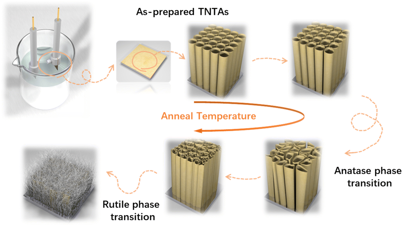 | ||
| Fig. 1 Schematic diagram of the relationship between the morphology and phase transition of TNTAs. | ||
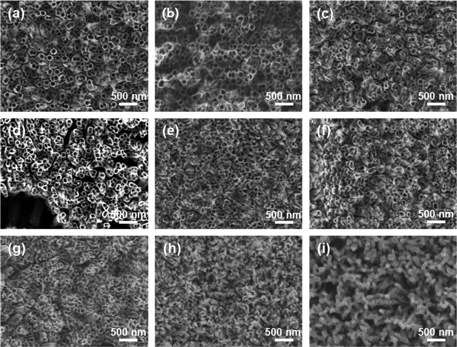 | ||
| Fig. 2 SEM images of TNTAs grown for 2 h and annealed at different temperatures: (a) 100 °C, (b) 200 °C, (c) 300 °C, (d) 400 °C, (e) 500 °C, (f) 600 °C, (g) 700 °C, (h) 800 °C, (i) 900 °C. | ||
To study the correlation between the morphological evolution and crystallization process of TNTAs, XRD and Raman investigations were conducted on TNTAs anodized for 2 h as shown in Fig. 3. When annealed at temperatures below 200 °C, all peaks in Fig. 3a (at 35.1, 38.4, 40.1, 53.0, 62.9, 70.6, 76.2, and 82.3°) belonged to the Ti substrate (PDF. 04-001-6809). The GIXRD results in Fig. 3c indicated that at this point, TNTAs exhibited no diffraction peaks, which is due to the fact that TNTAs grown via anodization are amorphous TiO2,22,23 and no crystallization occurs below 200 °C. The Raman spectrum in Fig. 3d also confirmed that TNTAs annealed below 200 °C did not undergo a phase transition, indicating that amorphous TNTAs can stably exist below 200 °C,24 and no crystalline phase is formed. This explains why there is no change in the morphology of TNTAs when annealed below 200 °C.
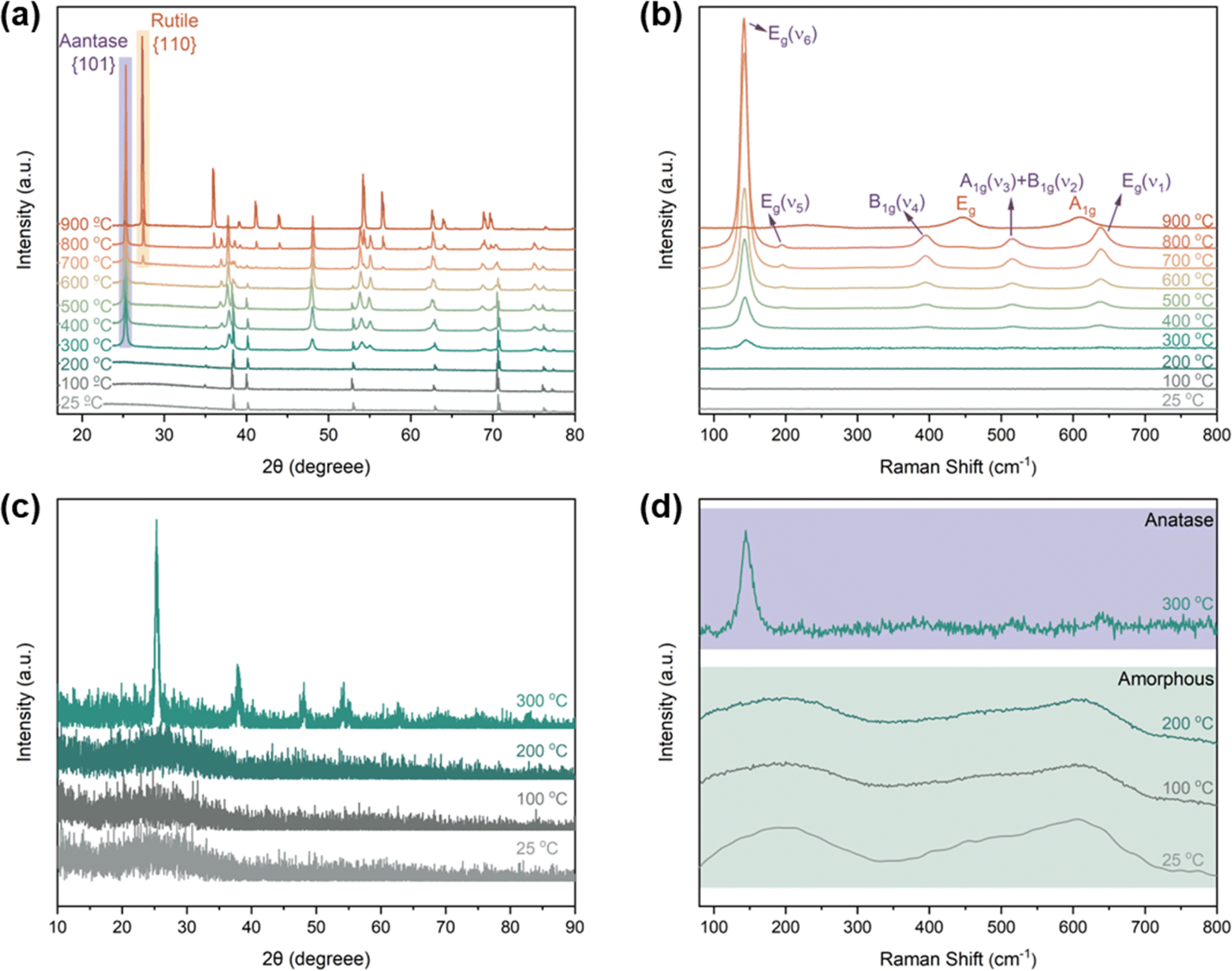 | ||
| Fig. 3 (a) XRD pattern of TNTAs grown for 2 h and annealed at different temperatures, (b) and (d) Raman patterns, (c) GIXRD patterns. | ||
As the temperature increased to 300 °C, the newly appeared peaks in Fig. 3a and c (at 25.3, 37.0, 37.9, 38.6, 48.0, 54.0, 55.1, 62.7, 68.9, and 75.2°) corresponded to the anatase phase of TiO2 (PDF. 01-075-2547).25 This indicates that at this temperature, TNTAs underwent a transition from an amorphous state to the anatase phase. In line with the XRD patterns, the Raman spectra at 300 °C in Fig. 3b and d also confirmed this transition, with the detection of Raman-active vibrations at 145 cm−1 characteristic of the anatase phase's Eg mode.26,27 From Fig. 2, it can be observed that when the temperature exceeds 300 °C, regular TNTAs undergo changes such as the curling deformation and partial collapse of nanotubes. However, the characteristic features of the nanotube array are still preserved, and these changes are closely associated with the anatase phase transition. Since 300 °C is the initial temperature for the amorphous-to-anatase phase transition,28 only sites with higher free energy undergo the phase change, so the overall structural impact is not very pronounced.
With further temperature increase, the XRD spectrum showed a significant increase in the intensity of the diffraction peaks corresponding to the {101} crystal planes of the anatase phase (labeled as anatase in Fig. 3a), indicating a continuous increase in the content of this phase, which is consistent with the results from the Raman spectrum. In the Raman spectrum, in addition to the changes in the intensity of the Eg mode, the high-frequency region's Raman peaks were well resolved. Vibrations observed at 395.0, 515.4, and 638.1 cm−1 were attributed to the anatase phase's B1g, A1g, and Eg modes, respectively.29,30 Comparing Fig. 2c–f, it can be observed that with the further increase in temperature, the extent of TNTAs' fragmentation gradually increases, while the nanotube structure remains. This phenomenon is attributed to the fact that TNTAs prepared through anodic oxidation in a fluoride-containing electrolyte are amorphous,31 containing many disordered structures and defects such as oxygen vacancies, dangling bonds, etc.32,33 After the anatase phase transition, it partially disrupts the nanotube array structure. Fig. 3d shows that amorphous TNTAs exhibit two distinct broad peaks. Although amorphous and anatase phases are entirely different in crystallography, amorphous structures with long-range disorder may have short-range atomic arrangements similar to the anatase phase. This characteristic allows the phase transition from amorphous to anatase not to cause destructive damage to the nanotube array structure. With increasing temperature, some of the curling and fragmentation of TNTAs may be attributed to the growth of anatase phase particles.
Upon annealing at 600 °C, peaks corresponding to the rutile phase of TiO2 (at 27.4, 36.1, 39.2, 41.2, 54.3, 56.6, 64.0, and 69.0°) began to appear in the XRD spectrum (PDF. 04-001-7096). However, in the Raman spectrum of TNTAs annealed at 600 °C, there were no new peaks, indicating that the transformation from anatase to rutile did not occur simultaneously on the surface and in the interior regions.34 The rutile phase primarily nucleated at the junction of the Ti substrate and TNTAs.35,36 Since the surface of TNTAs did not undergo the phase transition, there was minimal change in morphology compared to TNTAs annealed at 500 °C. The XRD spectrum of TNTAs annealed at 800 °C displayed a significant increase in the intensity of the peaks associated with the rutile phase, indicating a continued increase in the content of this phase, and the rutile phase transition persisted. A Raman peak at 446.9 cm−1 in Fig. 3b corresponded to the rutile phase's Eg mode,37 indicating that the surface also underwent rutile phase transformation at this stage, although the anatase phase still dominated. As seen in Fig. 2h, TNTAs had been severely damaged, with nanotube structures collapsing and visible particles. After annealing at 900 °C, both the XRD and Raman spectra exhibited drastic changes. The XRD peaks associated with the anatase phase significantly weakened and were replaced by newly emerging rutile peaks (labeled as rutile in the Fig. 3a). Spectral peaks at 446.9 and 609.6 cm−1 corresponded to the rutile phase's Eg and A1g Raman-active vibrations.38 At this point, the majority of TiO2 had transformed into the rutile phase, with only a very small amount of anatase phase remaining. As indicated in Fig. 2i, the nanotube morphology had disappeared, and the entire TNTAs had fully granulated. The relationship between the morphology of TNTAs and the phase transition is shown in Fig. 1.
3.2 The crystallization process of anatase TNTAs
The process of the crystalline transformation of TNTAs from amorphous to the anatase phase during annealing at 300 °C for different times was studied using Raman spectroscopy, as shown in Fig. 4a. After annealing for 3 minutes, characteristic Raman peaks of the anatase phase appeared in the spectrum, and with prolonged annealing time, these characteristic anatase peaks gradually strengthened, indicating an ongoing transformation to the anatase phase. According to previous research,27 anatase-phase TiO2 has six Raman-active vibrational modes: A1g + 2B1g + 3Eg. Each mode is labeled in Fig. 4a, and their corresponding molecular vibration diagrams are illustrated in Fig. 5. Eg(v6), Eg(v5), and B1g(v4) represent bending vibrations of O–Ti–O bonds, while A1g(v3), B1g(v2), and Eg(v1) correspond to stretching vibrations of Ti–O bonds. Due to the proximity in peak positions of A1g(v3) and B1g(v2), Raman spectra measured at room temperature often combine them into a single peak located at 516 cm−1.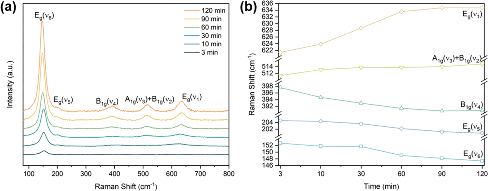 | ||
| Fig. 4 (a) Raman spectrum of TNTAs grown for 2 h and annealing at 300 °C, (b) peak positions of the five Raman peaks of anatase phase at 300 °C annealing versus annealing time. | ||
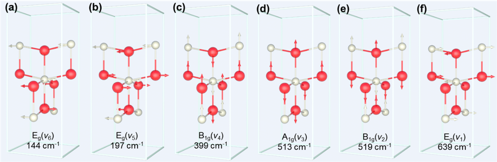 | ||
| Fig. 5 Schematic of molecular vibrations corresponding to six Raman active vibrations: (a) Eg(v6), (b) Eg(v5), (c) B1g(v4), (d) A1g(v3), (e) B1g(v2) and (f) Eg(v1). White spheres denote Ti atoms and red spheres O atoms. | ||
The relationship between the peak positions of the Raman peaks and annealing time was obtained by fitting the Raman peaks in Fig. 4a using Lorentzian functions, as shown in Fig. 4b. As annealing time increased, the Raman peak wavenumbers corresponding to Eg(v6), Eg(v5), and B1g(v4) decreased, indicating a redshift in the characteristic peaks associated with bending vibrations of O–Ti–O bonds (as shown in Fig. 5a–c). On the other hand, the Raman peak wavenumbers corresponding to A1g(v3), B1g(v2), and Eg(v1) increased, indicating a blueshift in the characteristic peaks associated with stretching vibrations of Ti–O bonds (as shown in Fig. 5d–f). The observed phenomenon can be explained by the relationship between vibrational frequencies and elastic constants. When TNTAs transform from amorphous to the anatase phase, bending vibrations become less favorable while stretching vibrations become more favorable. The reason for this change may be attributed to the release of distortions in the Ti–O octahedra during the annealing process. TNTAs prepared using anodic oxidation are amorphous and exhibit disordered atomic arrangements. The distorted Ti–O atomic configurations make bending vibrations more likely. During annealing, the release of distortions makes bending vibrations less favorable, while for stretching vibrations, the regular arrangement of Ti–O atomic configurations during annealing makes them more favorable, resulting in a shift toward higher frequencies in the Raman spectrum.
3.3 Study on the electrochemical performance of TNTAs
To assess the impact of the crystallization of amorphous TNTAs on their electrochemical performance, an estimation of the content of the amorphous phase, anatase phase, and rutile phase, as well as the size of anatase phase particles, was first conducted using XRD spectra. For samples containing only the anatase and rutile phases, the proportion of the rutile phase in XRD can be calculated using eqn (1):39
 | (1) |
 | (2) |
Since samples annealed at temperatures above 700 °C no longer contain an amorphous structure, eqn (1) can be used to calculate the content of the anatase and rutile phases in TNTAs annealed at different temperatures. For the samples annealed at temperatures below 700 °C, the content of the anatase and rutile phases can be calculated by comparing the integral areas of the diffraction peaks in the XRD patterns of these samples with those annealed at 700 °C.40,41 The grain size of the anatase particles can be calculated using the Debye–Scherrer formula as shown in eqn (2),42 where “D” represents the grain size (nm), “λ” is the wavelength of X-rays (0.1541 nm), “β” is the full width at half maximum (FWHM), and “θ” is the diffraction angle. Using these calculation methods, Lorentzian fitting was performed on the main peaks in the XRD data from Fig. 3a, and the results are shown in Table 1.
| Temperature/°C | Anatase {101} plane | Rutile {110} plane | ||||
|---|---|---|---|---|---|---|
| FWHM | Integral intensity | Integral areas | FWHM | Integral intensity | Integral areas | |
| 100 | — | — | — | — | — | — |
| 200 | — | — | — | — | — | — |
| 300 | 0.228 | 3978 | 1395 | — | — | — |
| 400 | 0.174 | 7425 | 1985 | — | — | — |
| 500 | 0.147 | 9469 | 2010 | — | — | — |
| 600 | 0.129 | 10087 |
1030 | 0.193 | 117 | 35 |
| 700 | 0.105 | 12604 |
2049 | 0.090 | 688 | 96 |
| 800 | 0.098 | 15406 |
2318 | 0.070 | 3629 | 391 |
| 900 | 0.144 | 375 | 78 | 0.101 | 16694 |
2591 |
Based on the fitting data obtained from Table 1, calculations were performed for the phase content and the grain size of anatase using eqn (1) and (2). The results are presented in Table 2 and Fig. 6.
| Temperature/°C | Phase content/% | Anatase particle size/nm | ||
|---|---|---|---|---|
| Amorphous | Anatase | Rutile | ||
| 100 | 100 | — | — | — |
| 200 | 100 | — | — | — |
| 300 | 35.9 | 64.1 | — | 35.71 |
| 400 | 8.8 | 91.2 | — | 49.92 |
| 500 | 7.6 | 92.4 | — | 55.47 |
| 600 | 4.6 | 93.3 | 2.1 | 62.92 |
| 700 | 0 | 94.2 | 5.8 | 77.87 |
| 800 | 0 | 79.0 | 21.0 | 82.86 |
| 900 | 0 | 1.9 | 98.1 | 56.58 |
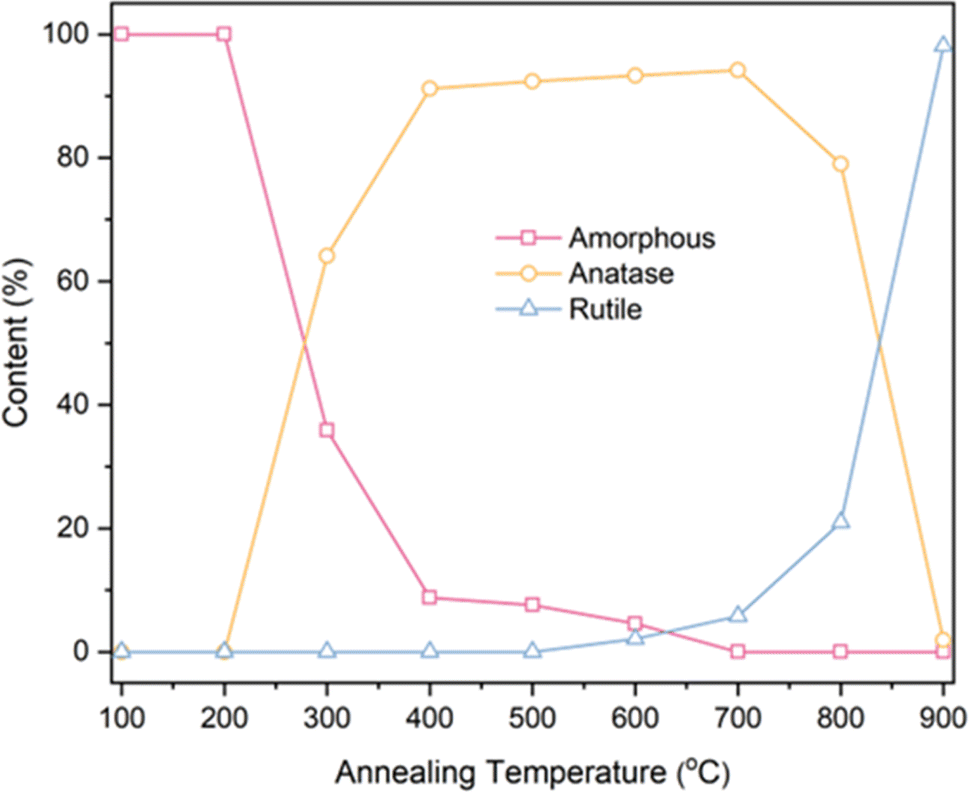 | ||
| Fig. 6 Phase content of TNTAs obtained by annealing at different temperatures after 2 h of anodizing. | ||
Based on the calculations in Table 2, the transformation of amorphous to anatase phase in TNTAs annealed for 2 h occurred between 200–300 °C and was mostly completed at 400 °C. The transformation to the rutile phase began at 600 °C and rapidly completed between 800–900 °C. As the annealing temperature increased, the size of the anatase particles gradually increased, starting from 35.71 nm and reaching 82.86 nm. However, between 800–900 °C, the particle size of the anatase phase decreased due to the transformation of anatase to rutile phase.
Numerous studies have been conducted on the use of TNTAs in lithium-ion batteries.19,32,43–45 Among the different types of TNTAs, amorphous TNTAs have shown better performance than crystalline TNTAs in terms of initial capacity, rate performance, electronic conductivity, and diffusion coefficient.46 However, amorphous TNTAs have poor cyclic stability, which limits their practical application in lithium-ion batteries.43 On the other hand, anatase TNTAs have better cyclic stability but lower capacity. Therefore, in recent years, research has focused on reducing the irreversible capacity and improving the cyclic stability of amorphous TiO2 while maintaining high capacity.45 Interestingly, the proportions of different phases in TNTAs can be controlled through annealing processes. To investigate the lithium-ion storage performance of TNTAs with different phase proportions, TNTAs obtained through 2 h anodization were annealed at various temperatures and assembled into TNTAs/Li half-cells for electrochemical performance testing. As shown in Fig. 7, the performance trend of TNTAs indicates that 300 °C is superior to 200 °C, which is superior to 400 °C, and so forth, with the order being 100 °C > 600 °C > 500 °C > 700 °C > 800 °C > 900 °C.
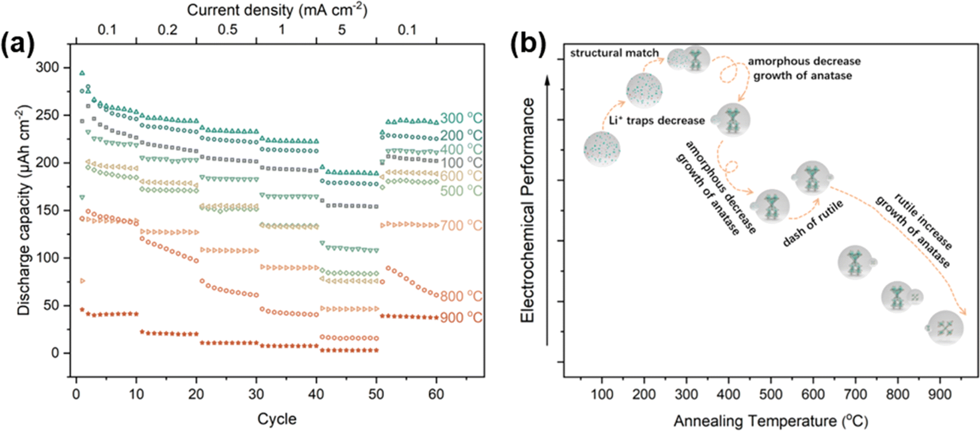 | ||
| Fig. 7 (a) High rate cycling performance of TNTAs grown for 2 h and annealing at different temperatures. Current density is 0.1–5 mA cm−2. (b) Relationship between electrochemical properties and annealing temperature. | ||
The superior performance of TNTAs annealed at 200 °C compared to those annealed at 100 °C suggests that during annealing, the reduction in the number of Li+ traps and defects in amorphous TNTAs leads to a decrease in irreversible capacity.46 Compared to amorphous TNTAs annealed at 100 °C and 200 °C, TNTAs annealed at 300 °C exhibit higher discharge capacity and better stability. According to the calculations in Table 2, the ratio of amorphous to anatase phases in TNTAs annealed at 300 °C is 35.9/64.1. It is noteworthy that the galvanostatic charge–discharge curves (Fig. S5a†) of TNTAs annealed at 300 °C do not show a voltage plateau, indicating that during charge–discharge processes, lithium-ion insertion and extraction primarily occur in the amorphous TiO2.47 The disordered structure and defects in the amorphous phase provide numerous insertion sites for lithium ions at relatively high potentials, thereby expanding the potential range of lithium-ions insertion reactions and facilitating uniform insertion and extraction of Li+ in the amorphous TiO2 nanotubes electrode without undergoing a two-phase reaction between LixTiO2 and TiO2.32,33,47 The high capacity and excellent stability of TNTAs annealed at 300 °C may be attributed to the structural match between the amorphous and anatase phases, where the amorphous phase provides larger discharge capacity while the anatase phase serves as a support within the TNTAs structure.
During the first 50 cycles, the performance of amorphous TNTAs annealed at 100 °C outperformed those annealed at 400 °C, indicating that the amorphous phase exhibits superior performance compared to anatase. However, when the current density is restored to 0.1 mA cm−2, the performance of TNTAs annealed at 400 °C surpasses that of the amorphous phase(annealed at 100 °C). From the charge–discharge curves in Fig. S5b,† a voltage plateau can be observed, corresponding to the insertion and extraction of lithium-ions in anatase. Although the appearance of anatase particles may weaken the performance of TNTAs, the structural combination of anatase and amorphous phases indeed improves the cyclic stability of amorphous TNTAs. Compared to TNTAs annealed at 400 °C, annealing at 500 °C results in a decrease in rate performance due to the increase in anatase particle size (from 49.92 to 55.47 nm).48 Interestingly, the performance of TNTAs annealed at 600 °C is superior to that at 500 °C. This phenomenon occurs because although the rutile phase TNTAs exhibit the poorest electrochemical performance, the lithium-ion diffusion coefficient of rutile TiO2 is 4–5 orders of magnitude larger than that of anatase, leading to the superior performance of the mixed phase TNTAs annealed at 600 °C compared to pure anatase phase TNTAs.47 The properties of different phases are shown in Fig. S6.† In the temperature range of 700–900 °C, the appearance of the rutile phase ultimately leads to a significant deterioration in performance.49
4. Conclusion
In this study, the amorphous TNTAs obtained through anodization were subjected to annealing in the temperature range of 100–900 °C to establish correlations between annealing temperature, morphology, structure, and performance. The length of the nanotubes exhibited a directly proportional to the anodization duration. Specifically, nanotubes anodized for 2, 5, and 10 h yielded lengths of approximately 7–10, 10–15, and 16–23 μm, respectively. With those anodized for 2 h showing dimensions of approximately 92 nm in inner diameter and 12 nm in wall thickness. SEM, XRD, and Raman analyses revealed that the transition from amorphous to anatase began at 300 °C without causing significant damage to the nanotube array structure. At 600 °C, the transformation to rutile occurred, leading to the complete particleization of the nanotube array. To investigate the amorphous-to-anatase transition, samples were annealed at 300 °C for different durations. Raman spectroscopy fitting showed that the bending vibrations became more difficult to occur, while stretching vibrations became easy to carry out during the transition, attributed to the release of distortions in the [TiO6] octahedra during the amorphous-to-anatase conversion. Utilizing XRD, estimations of phase content pertaining to the amorphous, anatase, and rutile phases, along with the particle size of anatase, were performed, followed by an exploration of their correlation with electrochemical performance. The results indicated that the samples annealed at 300 °C exhibited superior electrochemical performance, possibly stemming from the structural compatibility between the amorphous phase and diminutive anatase particles (approximately 35.71 nm in size). Moreover, within 300 and 800 °C range, an increase in annealing temperature corresponded to a gradual augmentation in the particle size of anatase, ranging from 34.71 nm to 82.86 nm. This increase in anatase particle size correlated with a decline in electrochemical performance, while a pronounced decrease was observed during the rutile phase transformation. Overall, this work successfully underscores the pivotal role of structural compatibility in the design of high-performance lithium-ion battery electrode materials.Conflicts of interest
There are no conflicts of interest to declare.Acknowledgements
This work was supported by International (regional) Cooperation and Exchange Projects of the National Natural Science Foundation of China (52220105010), Key Projects of the National Natural Science Foundation of China (51832007), Natural Science Foundation of Shandong Province (ZR2020ZD35).References
- N. Nashrah, A. Chaouiki, W. Al Zoubi and Y. G. Ko, Nano Mater. Sci., 2024 DOI:10.1016/j.nanoms.2023.09.007.
- E. Isik, L. B. Tasyurek, I. Isik and N. Kilinc, Microelectron. Eng., 2022, 262, 111834 CrossRef CAS.
- G. Cha, S. Ozkan, I. Hwang, A. Mazare and P. Schmuki, Surf. Sci., 2022, 718, 122012 CrossRef CAS.
- F. Zheng, F. Dong, L. Zhou, J. Yu, X. Luo, X. Zhang, Z. Lv, L. Jiang, Y. Chen and M. Liu, J. Rare Earths, 2023, 41, 539–549 CrossRef CAS.
- R. Aguirre Ocampo, M. Echeverry-Rendón, S. Robledo and F. Echeverría Echeverría, Mater. Chem. Phys., 2022, 275, 125137 CrossRef CAS.
- O. Zakir, E. Mountassir El Mouchtari, M. Elyaagoubi, E. Mersly Lekbira, R. Idouhli, A. Aityoub, M. Eddine Khadiri, S. Rafqah, A. Abouelfida and A. Outzourhit, J. Aust. Ceram. Soc., 2022, 58, 1389–1397 CrossRef CAS.
- A. Talla, N. J. Suliali, W. E. Goosen, Z. N. Urgessa, S. V. Motloung and J. R. Botha, Phys. B, 2022, 640, 414026 CrossRef CAS.
- M. Motola, L. Hromadko, J. Prikryl, H. Sopha, M. Krbal and J. M. Macak, Electrochim. Acta, 2020, 352, 136479 CrossRef CAS.
- P. Kubiak, J. Geserick, N. Hüsing and M. Wohlfahrt-Mehrens, J. Power Sources, 2008, 175, 510–516 CrossRef CAS.
- D. Regonini, C. R. Bowen, A. Jaroenworaluck and R. Stevens, Mater. Sci. Eng., R, 2013, 74, 377–406 CrossRef.
- L. A. García-Contreras, J. O. Flores-Flores, J. Á. Arenas-Alatorre and J. Á. Chávez-Carvayar, J. Alloys Compd., 2022, 923, 166236 CrossRef.
- C. Xing, L. Yang, R. He, M. C. Spadaro, Y. Zhang, J. Arbiol, J. Li, B. Poudel, A. Nozariasbmarz, W. Li, K. H. Lim, Y. Liu, J. Llorca and A. Cabot, Small, 2023, 19, 2303639 CrossRef CAS PubMed.
- M. Mansoorianfar, R. Rahighi, A. Hojjati-Najafabadi, C. Mei and D. Li, Mater. Des., 2021, 198, 109314 CrossRef CAS.
- M. L. Puga, J. Venturini, C. S. Ten Caten and C. P. Bergmann, Ceram. Int., 2022, 48, 19513–19526 CrossRef CAS.
- T. M. David, P. R. Dev, P. Wilson, P. Sagayaraj and T. Mathews, Electrochem. Sci. Adv., 2022, 2, e202100083 CrossRef CAS.
- I. Gavrilin, A. Dronov, R. Volkov, T. Savchuk, D. Dronova, N. Borgardt, A. Pavlikov, S. Gavrilov and D. Gromov, Appl. Surf. Sci., 2020, 516, 146120 CrossRef CAS.
- J. Zhang, J. Lu, P. Hou, Y. Liu, Z. Li, P. Lu, G. Wen, L. Liu and H. Sun, J. Alloys Compd., 2023, 952, 170010 CrossRef CAS.
- P. Roy, S. Berger and P. Schmuki, Angew. Chem., Int. Ed., 2011, 50, 2904–2939 CrossRef CAS PubMed.
- W. Cao, K. Chen and D. Xue, Materials, 2021, 14, 510 CrossRef CAS PubMed.
- Z. Yi, Y. Zeng, H. Wu, X. Chen, Y. Fan, H. Yang, Y. Tang, Y. Yi, J. Wang and P. Wu, Results Phys., 2019, 15, 102609 CrossRef.
- D. G. Li, D. R. Chen, J. D. Wang and P. Liang, Electrochim. Acta, 2016, 207, 152–163 CrossRef CAS.
- G. K. Mor, O. K. Varghese, M. Paulose and C. A. Grimes, Adv. Funct. Mater., 2005, 15, 1291–1296 CrossRef CAS.
- Y. Liao, W. Que, P. Zhong, J. Zhang and Y. He, ACS Appl. Mater. Interfaces, 2011, 3, 2800–2804 CrossRef CAS PubMed.
- J. Wang, L. Zhao, V. S. Y. Lin and Z. Lin, J. Mater. Chem., 2009, 19, 3682 RSC.
- T. Trung and C. Ha, Mater. Sci. Eng., C, 2004, 24, 19–22 CrossRef.
- W. Ma, Z. Lu and M. Zhang, Appl. Phys. A, 1998, 66, 621–627 CrossRef CAS.
- T. Ohsaka, F. Izumi and Y. Fujiki, J. Raman Spectrosc., 1978, 7, 321–324 CrossRef.
- J. Chen, Y. Fu, F. Sun, Z. Hu, X. Wang, T. Zhang, F. Zhang, X. Wu, H. Chen, G. Cheng and R. Zheng, Chem. Eng. J., 2020, 400, 125784 CrossRef CAS.
- T. Ohsaka, J. Phys. Soc. Jpn., 1980, 48, 1661–1668 CrossRef CAS.
- L. Miao, S. Tanemura, S. Toh, K. Kaneko and M. Tanemura, J. Cryst. Growth, 2004, 264, 246–252 CrossRef CAS.
- K. Zhu, N. R. Neale, A. Miedaner and A. J. Frank, Nano Lett., 2007, 7, 69–74 CrossRef CAS PubMed.
- A. Auer, D. Steiner, E. Portenkirchner and J. Kunze-Liebhäuser, ACS Appl. Energy Mater., 2018, 1, 1924–1929 CrossRef CAS.
- H. T. Fang, M. Liu, D. W. Wang, T. Sun, D. S. Guan, F. Li, J. Zhou, T. K. Sham and H. M. Cheng, Nanotechnology, 2009, 20, 225701 CrossRef PubMed.
- Y. Yang, X. Wang and L. Li, J. Am. Ceram. Soc., 2008, 91, 632–635 CrossRef CAS.
- D. Fang, Z. Luo, K. Huang and D. C. Lagoudas, Appl. Surf. Sci., 2011, 257, 6451–6461 CrossRef CAS.
- J. Zhang, M. Li, Z. Feng, J. Chen and C. Li, J. Phys. Chem. B, 2006, 110, 927–935 CrossRef CAS PubMed.
- Y. Zhang, C. X. Harris, P. Wallenmeyer, J. Murowchick and X. Chen, J. Phys. Chem. C, 2013, 117, 24015–24022 CrossRef CAS.
- M. Gotić, M. Ivanda, S. Popović, S. Musić, A. Sekulić, A. Turković and K. Furić, J. Raman Spectrosc., 1997, 28, 555–558 CrossRef.
- H. Zhang and J. F. Banfield, J. Phys. Chem. B, 2000, 104, 3481–3487 CrossRef CAS.
- K. Yanagisawa, K. Ioku and N. Yamasaki, J. Am. Ceram. Soc., 1997, 80, 1303–1306 CrossRef CAS.
- Y. Djaoued, R. Brüning, D. Bersani, P. P. Lottici and S. Badilescu, Mater. Lett., 2004, 58, 2618–2622 CrossRef CAS.
- Y. Rambabu, M. Jaiswal and S. C. Roy, Catal. Today, 2016, 278, 255–261 CrossRef CAS.
- Y. Jiang, C. Hall, N. Song, D. Lau, P. A. Burr, R. Patterson, D. Wang, Z. Ouyang and A. Lennon, ACS Appl. Mater. Interfaces, 2018, 10, 42513–42523 CrossRef CAS PubMed.
- V. Galstyan, J. M. Macak and T. Djenizian, Appl. Mater. Today, 2022, 29, 101613 CrossRef.
- M. Zhang, J. Chen, H. Li and C. Wang, Rare Met., 2021, 40, 249–271 CrossRef CAS.
- W. Ryu, D. Nam, Y. Ko, R. Kim and H. Kwon, Electrochim. Acta, 2012, 61, 19–24 CrossRef CAS.
- D. Guan, C. Cai and Y. Wang, MRS Online Proc. Libr., 2010, 1266, 7 Search PubMed.
- M. Wagemaker, W. J. H. Borghols and F. M. Mulder, J. Am. Chem. Soc., 2007, 129, 4323–4327 CrossRef CAS PubMed.
- V. Aravindan, Y. Lee, R. Yazami and S. Madhavi, Mater. Today, 2015, 18, 345–351 CrossRef CAS.
Footnote |
| † Electronic supplementary information (ESI) available. See DOI: https://doi.org/10.1039/d4ra00852a |
| This journal is © The Royal Society of Chemistry 2024 |