 Open Access Article
Application of static integrated skeletal reduction and tabulation of dynamic adaptive chemistry in the combustion simulation of ethylene-fueled scramjet combustor†
Zhongwen Liab,
Jianwen Liuc and
Jingbo Wang *ab
*ab
aSchool of Chemical Engineering, Sichuan University, Chengdu, 610065, P. R. China. E-mail: wangjingbo@scu.edu.cn
bEngineering Research Center of Combustion and Cooling for Aerospace Power, Ministry of Education, Sichuan University, Chengdu, 610065, P. R. China
cBeijing Power Machinery Institute, Beijing, 100074, P. R. China
First published on 8th May 2024
Abstract
The high-fidelity reduced mechanism is one of the key elements in the combustion simulation of scramjet combustors to reveal their combustion and flow phenomena. In the present work, the hierarchically constructed NUIGMech1.2 (2857 species and 11![[thin space (1/6-em)]](https://www.rsc.org/images/entities/char_2009.gif) 814 reactions) is applied to the combustion simulation of an ethylene-fueled scramjet combustor using the method of static integrated skeletal reduction and tabulation of dynamic adaptive chemistry (TDAC). The integrated skeletal reduction strategy successively consists of species elimination using the revised directed relation graph with error propagation method of fixed species scheme and improved sensitivity analysis method, and reactions elimination based on computational singular perturbation importance index. A preferred ethylene skeletal mechanism (26 species and 117 reactions) is obtained through the integrated skeletal reduction strategy under target working conditions of temperature range of 900–1800 K, pressure range of 1–4 atm, and equivalence ratio range of 0.25–5.0. The compact skeletal mechanism is comprehensively validated against the experimental results of ignition delay times, laminar flame speeds, and key species concentration profiles. Meanwhile, it shows consistent results with the detailed mechanism on the adiabatic flame temperature profiles and “S”-curves. When applying this skeletal mechanism to combustion simulations of ethylene-fueled scramjet combustor with double parallel cavities, the path flux analysis method and in situ adaptive tabulation algorithm of TDAC is further utilized to speed up the chemical reaction solution process at run-time. Under the scramjet and ramjet modes, the corresponding simulation results in terms of flame luminosity images, schlieren images, and static pressure distributions, coincide well with those of experimental measurements. The combustion and flow characteristics of the two modes are investigated and analyzed comparatively based on above results and combustion performance parameters. Present work contributes to the application of fuel kinetic mechanisms in scramjet combustor combustion simulation.
814 reactions) is applied to the combustion simulation of an ethylene-fueled scramjet combustor using the method of static integrated skeletal reduction and tabulation of dynamic adaptive chemistry (TDAC). The integrated skeletal reduction strategy successively consists of species elimination using the revised directed relation graph with error propagation method of fixed species scheme and improved sensitivity analysis method, and reactions elimination based on computational singular perturbation importance index. A preferred ethylene skeletal mechanism (26 species and 117 reactions) is obtained through the integrated skeletal reduction strategy under target working conditions of temperature range of 900–1800 K, pressure range of 1–4 atm, and equivalence ratio range of 0.25–5.0. The compact skeletal mechanism is comprehensively validated against the experimental results of ignition delay times, laminar flame speeds, and key species concentration profiles. Meanwhile, it shows consistent results with the detailed mechanism on the adiabatic flame temperature profiles and “S”-curves. When applying this skeletal mechanism to combustion simulations of ethylene-fueled scramjet combustor with double parallel cavities, the path flux analysis method and in situ adaptive tabulation algorithm of TDAC is further utilized to speed up the chemical reaction solution process at run-time. Under the scramjet and ramjet modes, the corresponding simulation results in terms of flame luminosity images, schlieren images, and static pressure distributions, coincide well with those of experimental measurements. The combustion and flow characteristics of the two modes are investigated and analyzed comparatively based on above results and combustion performance parameters. Present work contributes to the application of fuel kinetic mechanisms in scramjet combustor combustion simulation.
1. Introduction
Ethylene (C2H4) has the advantages of easy storage, short ignition delay time, and great energy per unit volume, which is also an important intermediate during oxidation and pyrolysis process of large hydrocarbons.1–5 Thus, it serves as fuel or surrogate fuel in practical scramjet combustors.3,6–11 Ethylene kinetic mechanism with high accuracy is one of the key elements for combustion simulation of ethylene-fueled scramjet combustors to reveal their combustion and flow phenomena.Global mechanisms of one step reaction12,13 or several steps of reactions with hydrogen (H2) and carbon monoxide (CO) as intermediates14–16 were adopted in previous combustion simulations of scramjet combustors.6,13,16–18 Due to the lack of universality of this kind of mechanisms, the prediction results gained are unsatisfactory under some circumstances,17,19 and the relevant combustion phenomena like flame propagation and dynamic evolution of combustion processes cannot be explained reasonably.20,21 Furthermore, they predict mostly incorrect trends or even fail to be solved in predicting fuel characteristics in kinetic simulations.20,22 In recent decades, a variety of detailed kinetic models related to ethylene–air combustion are developed.23–38 Among them, the NUIGMech1.2,38 including 2857 species and 11![[thin space (1/6-em)]](https://www.rsc.org/images/entities/char_2009.gif) 814 reactions, is hierarchically constructed that well characterize the combustion and pyrolysis characteristics for fuels ranging from C0–C7 hydrocarbons35,36,38–41 under wide working conditions. In terms of chemical kinetics, these mechanisms are good in predicting the characteristics of ethylene combustion. However, their large size leads to high computational cost when solving the corresponding chemical source terms and brings stiff problem to numerical solution.42,43 Thus, they cannot be directly applied to computationally expensive combustion simulation for ethylene-fueled scramjet combustors.
814 reactions, is hierarchically constructed that well characterize the combustion and pyrolysis characteristics for fuels ranging from C0–C7 hydrocarbons35,36,38–41 under wide working conditions. In terms of chemical kinetics, these mechanisms are good in predicting the characteristics of ethylene combustion. However, their large size leads to high computational cost when solving the corresponding chemical source terms and brings stiff problem to numerical solution.42,43 Thus, they cannot be directly applied to computationally expensive combustion simulation for ethylene-fueled scramjet combustors.
To facilitate the application of fuel mechanisms in combustion simulation of combustors, many mechanism reduction methods including skeletal reduction, lumping, time-scale analysis, etc., are developed in recent years to obtain skeletal mechanism without sacrificing accuracy on relevant combustion characteristics within a certain range of working conditions.42,44 Skeletal reduction as the main reduction method eliminates unnecessary species and reactions by dealing with complex coupling between species or reactions.42,44 Lu et al.45 first proposed the directed relation graph (DRG) method, and then a series of derivative methods including revised-DRG (r-DRG),46 DRG with error propagation (DRGEP),47 revised-DRGEP (r-DRGEP),44 path flux analysis (PFA),48 linearized error propagation (LEP),49 etc., are successively developed. Sensitivity analysis (SA) based methods are created later to aid reduction process, which eliminate unnecessary species by performing sensitivity analyses on certain retained species set. Given these methods are computationally expensive, they are often combined with DRG-related methods, and the corresponding methods include DRGASA,50 DRGEPASA51 and ISASA.52 Xue et al.44 recently proposed a fixed species (FS) scheme for six DRG-related methods to retain the species increasing the maximum error of ignition delay time sharply in skeletal reduction processes. The r-DRGEP method with the FS scheme showed good performance in the reduction of AramcoMech3.0![[thin space (1/6-em)]](https://www.rsc.org/images/entities/char_2009.gif) 33 for fourteen C0–C4 hydrocarbon and oxygenated fuels. Xi et al.53 improved SA method by introducing the scheme of recognition of strongly coupled species pairs and incremental deletion. As demonstrated in the reduction of n-heptane mechanism, the computational cost is greatly decreased compared with the traditional SA method. Moreover, reaction elimination methods for skeletal reduction are also developed, like elementary flux analysis (EFA)54 method and reaction elimination based on the computational singular perturbation (CSP) importance index.55 Lumping method is also introduced to reduce the mechanism size by combining similar species and reaction pathways.42 Although time-scale analysis reduction, such as quasi steady state approximation (QSSA),56,57 CSP,58 etc., can significantly reduce the mechanism size, the derived mechanism lacks universality for applications in customized or commercial software as reactions are not expressed in the extended Arrhenius format.59 In view of each reduction method is tailored for a certain reduction stage, integrated strategies are preferred in mechanism reduction process, which are proved to be reliable and efficient to achieve maximal reduction of many fuels.11,55,59
33 for fourteen C0–C4 hydrocarbon and oxygenated fuels. Xi et al.53 improved SA method by introducing the scheme of recognition of strongly coupled species pairs and incremental deletion. As demonstrated in the reduction of n-heptane mechanism, the computational cost is greatly decreased compared with the traditional SA method. Moreover, reaction elimination methods for skeletal reduction are also developed, like elementary flux analysis (EFA)54 method and reaction elimination based on the computational singular perturbation (CSP) importance index.55 Lumping method is also introduced to reduce the mechanism size by combining similar species and reaction pathways.42 Although time-scale analysis reduction, such as quasi steady state approximation (QSSA),56,57 CSP,58 etc., can significantly reduce the mechanism size, the derived mechanism lacks universality for applications in customized or commercial software as reactions are not expressed in the extended Arrhenius format.59 In view of each reduction method is tailored for a certain reduction stage, integrated strategies are preferred in mechanism reduction process, which are proved to be reliable and efficient to achieve maximal reduction of many fuels.11,55,59
Considering the application of reduction methods to the detailed mechanisms of ethylene, some skeletal mechanisms obtained under specific reduction conditions are summarized in Table 1. As for the detailed mechanisms adopted for reduction, Laskin Mech,23 USC-II,28 LLNL Mech24 and UCSD32 focus more on high temperature combustion of small hydrocarbons.34 GRI-Mech 3.0![[thin space (1/6-em)]](https://www.rsc.org/images/entities/char_2009.gif) 25 is mainly optimized for natural gas combustion. Therefore, these mechanisms are not well suited for wide conditions of ethylene combustion in combustion simulation of scramjet combustor. Different combustion characteristics can be as reduction target, such as ignition delay time (IDT), laminar flame speed (LFS), “S”-curve,60 the ignition characteristics deserve more attentions than other kinetics properties for scramjet combustors.4 Under narrow reduction conditions of single temperature and pressure point (298 K, 1 atm), a compact ethylene skeletal mechanism 23S–55R was obtained with an integrated reduction strategy. However, under wide temperature range of 800–1600 K, a larger skeletal mechanism 70S–451R was obtained by the single reduction method of DRGEP with FS scheme. Given the wide range of temperature, pressure, and equivalence ratio for scramjet combustor, there is still lack of a compact and comprehensively validated ethylene skeletal mechanism suitable for combustion simulation of scramjet combustors.
25 is mainly optimized for natural gas combustion. Therefore, these mechanisms are not well suited for wide conditions of ethylene combustion in combustion simulation of scramjet combustor. Different combustion characteristics can be as reduction target, such as ignition delay time (IDT), laminar flame speed (LFS), “S”-curve,60 the ignition characteristics deserve more attentions than other kinetics properties for scramjet combustors.4 Under narrow reduction conditions of single temperature and pressure point (298 K, 1 atm), a compact ethylene skeletal mechanism 23S–55R was obtained with an integrated reduction strategy. However, under wide temperature range of 800–1600 K, a larger skeletal mechanism 70S–451R was obtained by the single reduction method of DRGEP with FS scheme. Given the wide range of temperature, pressure, and equivalence ratio for scramjet combustor, there is still lack of a compact and comprehensively validated ethylene skeletal mechanism suitable for combustion simulation of scramjet combustors.
| Detailed mechanism | Target | Reduction method | Reduction conditionsa | Skeletal mechanismb |
|---|---|---|---|---|
| a Symbol T, p, and Φ respectively mean temperature, pressure, and equivalence ratio for reduction conditions.b Labelled by the number of species and reactions in the corresponding skeletal mechanism. | ||||
| Laskin Mech23 | — | DRGEPSA | T: 1100–1500 K | 25S–131R61 |
| p: 1 atm | ||||
| Φ: 1.0 | ||||
GRI-Mech 3.0![[thin space (1/6-em)]](https://www.rsc.org/images/entities/char_2009.gif) 25 25 |
— | DRG | T: 1300–1700 K | 19S–32R62 |
| CSP importance index | p: 1 atm | |||
| Φ: 0.4–1.4 | ||||
| UCSD32 | IDT | DRGEP | T: 1000–1800 K | 24S–86R11 |
| SA | p: 1.0–5.0 atm | |||
| CSP | Φ: 0.5–1.5 | |||
| USC-II28 | IDT | DRG | T: 1200–1800 K | 38S–230R63 |
| p: 1–3 atm | ||||
| Φ: 0.6–1.4 | ||||
| LLNL Mech24 | LFS | DRGEP | T: 298 K | 23S–55R64 |
| QSSA | p: 1 atm | |||
| SA | Φ: 0.6–1.2 | |||
| USC-II28 | “S”-curve | LEP | T: 1000 − (adiabatic flame temperature − 100) K | 35S–228R49 |
| p: 0.5–10 atm | ||||
| Φ: 0.5–1.5 | ||||
AramcoMech 3.0![[thin space (1/6-em)]](https://www.rsc.org/images/entities/char_2009.gif) 33 33 |
IDT | DRGEP with FS | T: 800–1600 K | 70S–451R44 |
| p: 1–10 atm | ||||
| Φ: 0.5–1.5 | ||||
| USC-II28 | IDT | PFA modified SA | T: 1500–2500 K | 26S–55R65 |
| p: 20–60 atm | ||||
| Φ: 0.5–1.5 | ||||
The tabulation of dynamic adaptive chemistry (TDAC) method is proved to be a promising method to utilize skeletal or detailed mechanisms in combustion simulation of combustors.66–69 The TDAC method66 reduce prohibitive computational cost in the solution of species transport equations by coupling in situ adaptive tabulation algorithm (ISAT)70 and dynamic adaptive chemistry (DAC).71 The ISAT algorithm decreases the effect of the number of cells by tabulating and reusing previously solutions, whereas the DAC method decreases the effect of the mechanism size by acquiring local reduced mechanisms at run-time.66–68 Preliminary static reduction of detailed mechanisms before applying DAC or TDAC method can dramatically decrease computational cost and storage requirements while guaranteeing accuracy and good acceleration performance.67,68,71,72 Li et al.67 evaluated the speed-up performance of different dynamic reduction methods (DRG, DRGEP, DAC, PFA, and EFA) with ISAT turned on for skeletal and detailed mechanisms of natural gas and biogas in combustion simulation of Delft jet in hot co-flow (DJHC) burner, and found that PFA provides a slightly larger speed-up factor for skeletal mechanism.
Considering the extensive applications of ethylene as fuel or surrogate fuel and the lack of its skeletal mechanism with high-fidelity applicable for wide range of operating conditions of scramjet combustors, present work aims to obtain a compact and comprehensively validated ethylene skeletal mechanism based on the development of ethylene mechanisms and newly proposed mechanism reduction methods. A static integrated skeletal reduction is performed for the high accuracy NUIGMech1.2![[thin space (1/6-em)]](https://www.rsc.org/images/entities/char_2009.gif) 38 containing ethylene sub-mechanism to obtain a preferred skeletal mechanism under target operating conditions. After systematic kinetic verifications for reliability on the skeletal mechanism, it is applied to the combustion simulations of an ethylene-fueled scramjet combustor combined with the TDAC method.66 And then the flow and combustion characteristics under a scramjet and a ramjet operating modes are investigated according to the results of combustion simulations and the discussion of combustion performance parameters.
38 containing ethylene sub-mechanism to obtain a preferred skeletal mechanism under target operating conditions. After systematic kinetic verifications for reliability on the skeletal mechanism, it is applied to the combustion simulations of an ethylene-fueled scramjet combustor combined with the TDAC method.66 And then the flow and combustion characteristics under a scramjet and a ramjet operating modes are investigated according to the results of combustion simulations and the discussion of combustion performance parameters.
2. Computational specifications
2.1. Static reduction setup
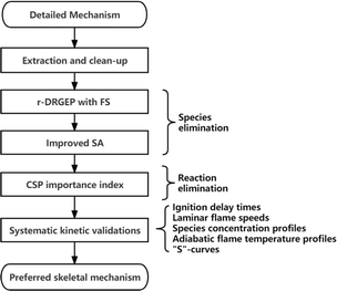
The flowchart of the static integrated reduction with NUIGMech1.2![[thin space (1/6-em)]](https://www.rsc.org/images/entities/char_2009.gif) 38 as the detailed mechanism is illustrated in Fig. 1. Mechanism extraction and clean-up is first carried out to extract sub-mechanism of species with carbon number ≤4 (including H2 mechanism) and clean unnecessary sub-mechanisms of NOx and NH3. According to the operating conditions of the ethylene-fueled scramjet combustor,3,5,10,11,22,73 the temperature range of 900–1800 K, pressure range of 1–4 atm, and equivalence ratio range of 0.25–5.0 are chosen as the reduction conditions. The cost-effective r-DRGEP with FS method44 and the efficient but slightly expensive improved SA method53 are employed to perform the two stage species eliminations, followed by the reactions elimination based on the method of CSP importance index.55 Systematic kinetic verifications are conducted on the preferred skeletal mechanism intended for combustion simulation to check its reliability. These verifications, including ignition delay times (IDTs), laminar flame speeds (LFSs), species concentration profiles (SCPs), adiabatic flame temperature profiles (AFTPs) and “S”-curves, are performed by the Chemkin-pro package.74 Present integrated skeletal reduction is performed by the automatic mechanism reduction program ReaxRed44,75 adopting the relative error of IDTs as the indicator, which has proven to be effective in extensive reduction practices.44,53,55,76,77
38 as the detailed mechanism is illustrated in Fig. 1. Mechanism extraction and clean-up is first carried out to extract sub-mechanism of species with carbon number ≤4 (including H2 mechanism) and clean unnecessary sub-mechanisms of NOx and NH3. According to the operating conditions of the ethylene-fueled scramjet combustor,3,5,10,11,22,73 the temperature range of 900–1800 K, pressure range of 1–4 atm, and equivalence ratio range of 0.25–5.0 are chosen as the reduction conditions. The cost-effective r-DRGEP with FS method44 and the efficient but slightly expensive improved SA method53 are employed to perform the two stage species eliminations, followed by the reactions elimination based on the method of CSP importance index.55 Systematic kinetic verifications are conducted on the preferred skeletal mechanism intended for combustion simulation to check its reliability. These verifications, including ignition delay times (IDTs), laminar flame speeds (LFSs), species concentration profiles (SCPs), adiabatic flame temperature profiles (AFTPs) and “S”-curves, are performed by the Chemkin-pro package.74 Present integrated skeletal reduction is performed by the automatic mechanism reduction program ReaxRed44,75 adopting the relative error of IDTs as the indicator, which has proven to be effective in extensive reduction practices.44,53,55,76,77
2.2. Computational domain and boundary conditions
The structure and experimental measurement data of investigated model scramjet combustor are taken from the researches of Zhong et al.3,10 As shown in Fig. 2(a), the scramjet combustor consists of an isolator section of 674 mm in length (equal-area of 75 mm × 54.5 mm), and three unilaterally diverging combustor sections with lengths of 480 mm, 702 mm, and 344 mm, respectively. The divergence angles are 2.5°, 3.5°, and 4° in sequence. Two integrated fuel-injection/flame-holder cavity modules are installed on the upper and lower walls of combustor Section I. The fuel-injection part is located 8 mm upstream of the leading edge of the cavity and has three 2.0 mm diameter holes symmetrically spaced 18 mm apart. The depth, length, width, and aft ramp angle of flame-holder cavity are respectively 15 mm, 110 mm, 75 mm, and 45°. For more details on the combustor configuration, the experimental setup and data measurements please refer to the experimental researches.3,10 According to the mesh independent analysis in ESI,† the hexahedral structured mesh containing approximately 4.89 million cells is utilized to discrete the computational domain, as illustrated in Fig. 2(b) and (c). The outer and inner O grid block schemes are adopted for six ethylene jet holes, and the cells are clustered towards shear layers of cavities and downstream of the ethylene jets.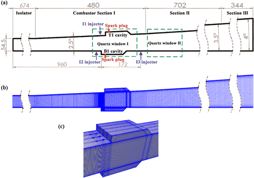 | ||
| Fig. 2 (a) The schematic diagram of scramjet combustor10 (unit in mm); (b) Ooverall computational mesh; (c) mesh refinement around integrated fuel-injection/flame-holder cavity modules. | ||
The total temperature T0, total pressure p0, and Mach number Ma of the vitiated air at combustor inlet is about 1430 K, 3.6 MPa, and 3.46. The ethylene injection pressure of injectors I1 and I2 are used to adjust the global equivalence ratio to perform a series of combustion experimental studies and there is a certain degree of fluctuations in the injection pressure of the ethylene jets.10 In the present work, combustion simulations are performed for two typical operating conditions with relatively comprehensive experimental data belonging to a scramjet (Φ = 0.26) and a ramjet (Φ = 0.51) operating mode.10 Their mode classifications are based on the quasi-one-dimensional (1-D) data analysis method.78 The flow parameters and components (in mass fraction) of the vitiated air and fuel jets prescribed under the two modes are summarized in Table 2. The turbulent intensities I of vitiated air and ethylene jets are taken as 1% and 5%. The turbulent kinetic energy k and specific dissipation rate ω are respectively estimated by 1.5(UI)2 and k0.5/(Cμ0.25l), where U is the magnitude of velocity and constant Cμ equals to 0.09. Turbulent length scale l is calculated by 0.07L, where the relevant dimension L are the diameter of the injector for ethylene jets and the hydraulic diameter for combustor inlet. Wall functions of kqRWallFunction, omegaWallFunction, alphatWallFunction, and nutkWallFunction are adopted and targeted for high Reynolds number flow to model corresponding turbulence variables in boundary layers.
| Parameter | Vitiated air | Scramjet mode | Ramjet mode |
|---|---|---|---|
| Φ | — | 0.26 | 0.51 |
| T0 [K] | 1430 | 305 | 305 |
| T [K] | 485.68 | 272.37 | 272.37 |
| p0 [Pa] | 3.60 × 10⁶ | 1.06 × 10⁶ | 2.05 × 10⁶ |
| p [Pa] | 4.00 × 10⁴ | 5.90 × 10⁵ | 1.14 × 10⁶ |
| Ma | 3.46 | 1.00 | 1.00 |
| U [m s−1] | 1491.29 | 316.30 | 316.30 |
| YO2 | 0.2495 | 0.00 | 0.00 |
| YH2O | 0.0356 | 0.00 | 0.00 |
| YCO2 | 0.1414 | 0.00 | 0.00 |
| YN2 | 0.5735 | 0.00 | 0.00 |
| YC2H4 | 0.00 | 1.00 | 1.00 |
2.3. Numerical simulation setup
The combustion simulations are carried out using the high speed gas phase compressible combustion solver79 developed on the open-source platform OpenFOAM.80 The inviscid convective fluxes are evaluated by Kurganov and Tadmor (KT) scheme81,82 that considers the wave transmission speed based on the central scheme, and determines a smaller dissipation coefficient according to the wave speed. Second-order backward time integration scheme is used.83 Second-order total variation decreasing scheme (van Leer flux limiter84) is used for divergence schemes of velocity, species mass fraction, internal energy, and turbulence variable fluxes. Laplacian schemes are Gauss linear corrected and the surface normal gradient scheme is corrected. The gradient schemes of turbulence variables, velocity, and pressure are cellLimited Gauss Linear 1, and the others are Gauss linear by default. The interpolation scheme for the reconstructed density, velocity, temperature, and species mass fraction is van Leer and the others are linear by default. Ignition in simulation is accomplished by means of adding energy source terms in the patch region over a period. Adjustable time step is used and the maximum Courant–Friedrichs–Lewy (CFL) number is set to 0.3. Turbulent Schmidt number Sct and turbulent Prandtl number Prt are respectively set to 0.9 and 0.72.The SST k–ω turbulence model85–87 and the partially stirred reactor (PaSR) combustion model88–90 are respectively used to model turbulent flow, turbulence and combustion interaction. The model constant Cmix in PaSR is taken as 0.01.16,22 The mechanism reduction method for TDAC part is PFA reduction method48,67 and ISAT algorithm.70 On the TDAC reduction, the ISAT tabulation tolerance εISAT and the reduction tolerance εPFA are both set to 1 × 10⁻⁴ according to previous related studies.66–68 Previous studies indicated that thermal radiation can affect the combustion characteristics of premixed combustible mixtures in one-dimensional laminar burning velocity.91,92 Whereas the radiation effect is usually ignored in the combustion simulations in engineering scale scramjet combustors,17,22,73,93 and therefore its effect is not considered in current simulations.
3. Results and discussions
3.1. Acquisition of preferred skeletal mechanism and its systematic kinetic verifications
Following the scheduled strategy in Fig. 1, the skeletal reduction is carried out for NUIGMech1.2 by setting the maximum relative error (MaxRE) of IDTs ≤20%![[thin space (1/6-em)]](https://www.rsc.org/images/entities/char_2009.gif) 34 under the target reduction conditions. The ethylene skeletal mechanisms obtained at different stages are summarized in Table 3. After the first stage of species eliminations using r-DRGEP with FS scheme,44 the obtained skeletal mechanism 44S–217R is significantly reduced compared to the pre-processed mechanism 581S–3200R. A more compact skeletal mechanism 26S–153R is derived in the second stage reduction for uncertain species set by adopting the improved SA method53 with a slight increase in the mean relative error (MeanRE) of IDTs from 5.07% to 6.40%. After elimination of unimportant reactions based on the method of CSP importance index,55 the skeletal mechanism 26S–117R is obtained with the MeanRE of 7.16%. Given its compact size and the ability to predict IDTs within reasonable accuracy,34 the mechanism 26S–117R is chosen as the preferred skeletal mechanism. Its comprehensive kinetic verifications concerning IDTs, LFSs, SCPs, etc. under the present reduction conditions are respectively shown in Fig. 3–7. Furthermore, considering the mechanisms applicable for ethylene combustion, such as mechanisms of 24S–86R,11 35S–228R,49 38S–230R,63 and 70S–451R44 in Table 1, their kinetic performances are systematically compared with the preferred skeletal mechanism obtained in present work in the ESI.† Compared to these mechanisms, the preferred skeletal mechanism has the advantages of favourable prediction results and compact in size.
34 under the target reduction conditions. The ethylene skeletal mechanisms obtained at different stages are summarized in Table 3. After the first stage of species eliminations using r-DRGEP with FS scheme,44 the obtained skeletal mechanism 44S–217R is significantly reduced compared to the pre-processed mechanism 581S–3200R. A more compact skeletal mechanism 26S–153R is derived in the second stage reduction for uncertain species set by adopting the improved SA method53 with a slight increase in the mean relative error (MeanRE) of IDTs from 5.07% to 6.40%. After elimination of unimportant reactions based on the method of CSP importance index,55 the skeletal mechanism 26S–117R is obtained with the MeanRE of 7.16%. Given its compact size and the ability to predict IDTs within reasonable accuracy,34 the mechanism 26S–117R is chosen as the preferred skeletal mechanism. Its comprehensive kinetic verifications concerning IDTs, LFSs, SCPs, etc. under the present reduction conditions are respectively shown in Fig. 3–7. Furthermore, considering the mechanisms applicable for ethylene combustion, such as mechanisms of 24S–86R,11 35S–228R,49 38S–230R,63 and 70S–451R44 in Table 1, their kinetic performances are systematically compared with the preferred skeletal mechanism obtained in present work in the ESI.† Compared to these mechanisms, the preferred skeletal mechanism has the advantages of favourable prediction results and compact in size.
| Methods | Skeletal mechanisms | MaxREa | MeanREa |
|---|---|---|---|
| a Maximum relative error and mean relative error under the reduction conditions. | |||
| Extraction and clean-up | 581S–3200R | — | — |
| r-DRGEP with FS | 44S–217R | 16.24% | 5.07% |
| r-DRGEP with FS + improved SA | 26S–153R | 14.94% | 6.40% |
| r-DRGEP with FS + improved SA + CSP importance index | 26S–117R | 16.19% | 7.16% |
Auto-ignition of fuel accounts for flame stabilization mechanism in combustion simulations of scramjet combustors,94,95 so the ability to accurately predict IDTs is an important aspect of high-fidelity skeletal mechanism.4 The ignition data for wide range conditions of ethylene/air mixtures in a shock tube was recently supplemented by Yang et al.34 The relevant experimental data and simulation settings are adopted in present work to show the performance of the skeletal mechanism. As illustrated in Fig. 3, the skeletal mechanism well reproduces the simulation results of the detailed mechanism under various conditions, and its prediction results match well with the experimental data. The pressure effect and the two cross-effects34,96,97 under lean-burn conditions are accurately captured by the skeletal mechanism.
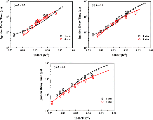 | ||
| Fig. 3 Validation of IDTs of ethylene/air mixture for the skeletal mechanism under the wide temperature, pressures of 1, 4 atm and different equivalence ratios. Symbols are experimental data;34 solid lines are predictions using the skeletal mechanism; dashed lines are predictions using NUIGMech1.2. | ||
Although the diffusion process is one or more orders of magnitude slower than the fluid-dynamic time scales at high speed situation, the residence time can be distinctly longer in recirculation zone (Ma ≈ 0) formed by flameholder, hence the accurate prediction of LFSs becomes significant for the skeletal mechanism.4 Fig. 4 displays the simulation results of LFSs of the skeletal and the detailed mechanism for ethylene/air mixtures under various equivalence ratios. Under the conditions of 298 K with initial pressures of 1 and 2 atm, the skeletal mechanism gives slightly larger simulation results than those of detailed mechanism. As shown in Fig. 4(b), the skeletal mechanism improves the insufficient prediction of the detailed mechanism under the conditions of 1 atm with initial temperatures of 298, 360 and 470 K, and the corresponding results are more in line with experimental data. Overall, the skeletal mechanism captures the pressure and temperature effect under the tested conditions.
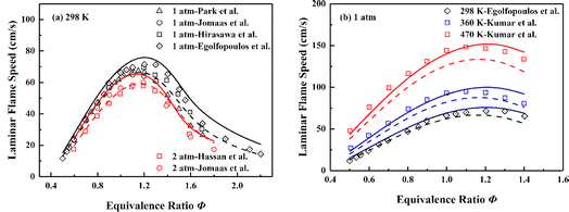 | ||
| Fig. 4 Validation of LFSs of ethylene/air mixture of various equivalence ratios at different initial pressures and temperatures. Symbols are experimental data;98–103 solid lines are predictions using the skeletal mechanism; dashed lines are predictions using NUIGMech1.2. | ||
The SCPs obtained in a jet-stirred reactor (JSR) characterize the evolution process on the consumption and production of interested species under operating conditions. Jallais et al. conducted JSR experiments on the oxidation of ethylene under various conditions (T = 773–900 K, p = 1.0 atm, and Φ = 3, 5, and 10).104 The initial mole fraction is 0.05 for ethylene diluted by N2, and the residence time is 1.3 s. The simulated concentration profiles of fuel (C2H4), and major products (CO, CO2) against experimental data in ethylene oxidation at different equivalence ratios are shown in Fig. 5. From the comparison results, the conclusion can be safely drawn that the skeletal mechanism presents good prediction for fuel consumption and major products generation in ethylene oxidation process.
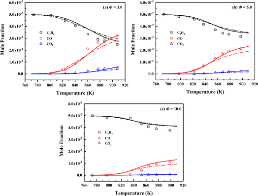 | ||
| Fig. 5 Validation of SCPs of fuel and major products for C2H4/O2/N2 mixtures of different equivalence ratios at the pressure of 1.0 atm and temperature range of 773–900 K. Symbols are experimental data;104 solid lines are predictions using the skeletal mechanism; dashed lines are predictions using NUIGMech1.2. | ||
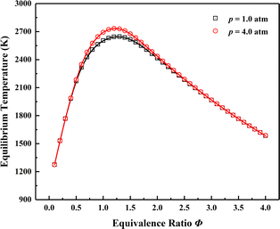
AFTPs are of paramount importance to characterize the stable combustion region when analysing premixed flames.105,106 Fig. 6 shows the comparison of AFTPs at equivalence ratio rang of 0.1–4.0 under initial temperature of 1000 K and pressures of 1.0 and 4.0 atm. The initial temperature is determined by the non-reactive temperature field adjacent to the two cavities with fuel injected, and the fuel and oxidizer are respectively ethylene and the vitiated air mentioned in Table 1. The obtained AFTPs are basically indistinguishable, which verifies the reliability of the thermochemical characteristics.
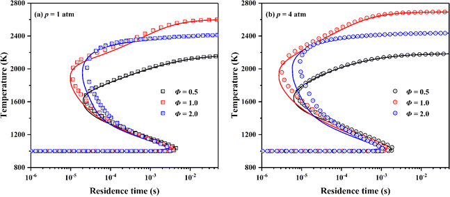
“S”-curve characterizes the variation of combustion state of premixed mixture in perfectly stirred reactor (PSR) with residence time.49,60 For the large span of residence time for scramjet combustor combustion conditions,22 the skeletal mechanism should maintain the prediction performance of the detailed mechanism on the combustion state of ignition, extinction, intermediate unstable combustion, and stable combustion of premixed mixture. Fig. 7 presents the simulation results of “S”-curves simulated by the detailed and the skeletal mechanism at equivalence ratios of 0.5, 1.0 and 2.0 and pressures of 1 and 4 atm. Same to the simulation setting in AFTPs, the fuel and oxidizer are respectively ethylene and the vitiated air, and the initial temperature of PSR is 1000 K. The skeletal mechanism accurately captures important combustion state of premixed mixture of different equivalence ratios and pressures in combustion process.
According to above systematic kinetic verifications, the simulation results of the skeletal mechanism are in good agreement with the experimental measurements for IDTs, LFSs, and SCPs. Meanwhile, it provides consistent results with the detailed mechanism in the aspects of AFTPs and “S”-curves. Additionally, reaction path analyses of the detailed mechanism and the skeletal mechanism for the ignition moments relevant to combustion conditions are provided in ESI.† As can be concluded from the analysis results, the preferred skeletal mechanism retains dominant key reaction pathways of ethylene combustion processes. Therefore, this compact and high-fidelity skeletal mechanism is well prepared for the combustion simulations of scramjet combustor in the subsequent section.
3.2. Application of the skeletal mechanism in combustion simulations
With the customized solver developed on OpenFOAM platform,79 the comparison of the computational efficiencies of the skeletal mechanisms of 44S–217R versus 26S–117R is carried out under other identical setups for combustion simulations. For the commonly adopted direct stiff integration chemical solution method, the test results indicate that the latter achieves 1.74 times acceleration performance than the former. Considering the TDAC method is utilized to speed up the chemical solution process at run-time, the comparison of computational efficiency between the TDAC method and the traditional direct stiff integration method is also performed for the preferred skeletal mechanism 26S–117R. Corresponding test results demonstrate that the former provides approximately 2.71 times acceleration performance compared to the latter. According to the above results, it can be further proved that the computational efficiency can be significantly improved by performing multi-stage integrated skeletal reduction and using the TDAC method. Thus, subsequent combustion simulations for the scramjet combustor adopt the skeletal mechanism 26S–117R of ethylene and the TDAC method. Two typical operating conditions of a scramjet mode and a ramjet mode are investigated to reveal their flow and combustion characteristics. The corresponding simulation results on reactive flow field against experimental measurements10 of flame luminosity images, schlieren images, static pressure distribution profiles are presented in Fig. 8–10. Flame luminosity image can intuitively characterize the outline of combustion zones and serve for the flame stabilization mechanism analysis in scramjet combustors.10,107,108 The flame luminosity is usually reflected by temperature contours in combustion simulation.17,18 Fig. 8 illustrates the simulated temperature contours of the central cross-section for the two operating modes. Simulation results well characterize the combustion characteristics around the two cavities in both operating modes and match well with those of experimental measurements. The thermodynamic throats formed owing to combustion heat release are comparable to those observed in experiments. Besides, the spreading angles obtained from the simulations are in good agreement with the corresponding experimental measurements for the two operating modes. The flames near the T1 and B1 cavities are visually nearly identical for the scramjet mode, whereas significant differences are recognized between the two flames for the ramjet mode, with distinct flame upstream propagation observed near the T1 cavity. Wang et al.109 summarized three different combustion stabilization mechanisms for cavity-based scramjet combustor based on optical observations. On the flames in both T1 and B1 cavities of the scramjet mode, the combustion stabilization attributes to cavity assisted jet-wake stabilized combustion. Whereas for the ramjet mode, the flames in T1 and B1 cavities respectively belong to combined cavity shear-layer/recirculation stabilized combustion and cavity shear-layer stabilized combustion.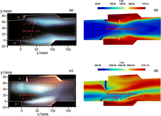 | ||
| Fig. 8 The comparison between the experimental flame luminosity images (left column) and the numerical results (right column). (a) and (b) for the scramjet mode; (c) and (d) for the ramjet mode. | ||
Schlieren images are especially applicable to measuring density gradient in compressible flow fields, which can be used to capture shock and expansion waves, and turbulent structures in mixing and wake flows.110 The numerical schlieren images (calculated by |∇ρ|) under the two operating modes are presented in Fig. 9 against corresponding experimentally measured images. In general, the numerical schlieren images well capture the complex structure of shock and expansion waves and their complex interaction with ethylene jets. For the scramjet mode as shown in Fig. 9(a) and (b), the heat release of combustion is quite small and the thermal blockage has minor effect on the mainstream. Pre-combustion shock waves is generated upstream of the two cavities due to the slightly flame upstream propagation and the formation of small recirculation zones ahead of the ethylene jets.10 Since combustion occurs mainly in ethylene jet-wake and cavity, cavity shear layers are slightly curved towards the mainstream side. The shock waves are reflected between the shear layers with gradually decreasing intensity. For the ramjet mode as illustrated in Fig. 9(c) and (d), the increase of global equivalence ratio results in more heat release, and then has a greater effect on the mainstream. Due to the intense thermal blockage, the mainstream is significantly slowed down before entering the combustor and the pre-combustion shock waves shift forward. Meanwhile, the different flow characteristics presented by ethylene jets injected by the I1 and I2 injectors using the same injection pressure are well reproduced by the numerical schlieren images for both modes.
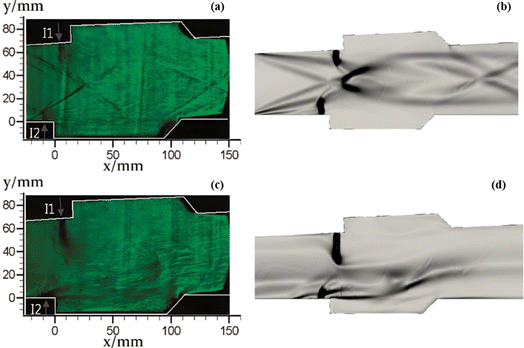 | ||
| Fig. 9 The comparison of experimental measured schlieren images (left column) and numerical schlieren images (right column). (a) and (b) for the scramjet mode; (c) and (d) for the ramjet mode. | ||
The static pressure profiles along the combustor directly reflect the intensity and distribution of combustion heat release.10 Fig. 10 provides the simulated pressure profiles along the centreline of the upper wall for the two combustion modes. The simulated pressure profiles coincide well with the corresponding experimental measurements in terms of the initial pressure rise location and the pressure rise ratio. For the scramjet mode, the heat release intensity is low and the static pressure rise is mainly limited in T1 cavity and its downstream. Whereas for the ramjet mode, more intense and sufficient combustion around T1 cavity and its downstream causes the static pressure increased significantly. Consistent with Fig. 8(c), the high back pressure caused by intense heat release leads to remarkable flame upstream propagation and the formation of recirculation zone in the upstream of T1 cavity.10
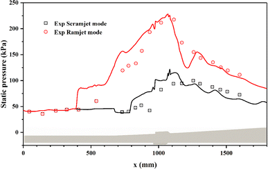 | ||
| Fig. 10 The comparison of static pressure profiles for the two combustion modes. Symbols are experimental data; solid lines are simulated results. | ||
Above detailed comparison and discussion demonstrates that present combustion simulation obtains reliable results using the ethylene skeletal mechanism, which further illustrates the applicability of the skeletal mechanism derivate from the integrated reduction strategy. The corresponding files of kinetic, thermodynamic, and transport data for this mechanism are provided in the ESI.† To further demonstrate the advantage of this mechanism, the corresponding combustion simulation results of the skeletal mechanism 26S–117R are compared with those of other mechanisms in related works. Detailed comparisons and discussions, as given in the ESI,† demonstrate that present skeletal mechanism gives predictions more in line with corresponding experimental measurements. Based on the numerical simulation results, present work further analyses combustion performance parameters including combustion efficiency ηcomb,93 total pressure loss ηpt,loss,93 and net thrust ΔF,12 which are difficult to measure experimentally but are important for combustor design. The definitions of these parameters are given by eqn (1)–(3).
 | (1) |
 | (2) |
 | (3) |
Fig. 11 compares the combustion performance parameters of the two operating modes. For the scramjet mode, the combustion intensity is weak in the wake of ethylene jets and cavities. The combustion efficiency gradually increases as combustion proceeds in the near-wall region downstream of the parallel cavities. For the ramjet mode, the recirculation zone generated around the T1 cavity provides favourable combustion conditions, thus higher combustion efficiency is achieved near here. From x = 1800 mm, the combustion efficiency of the scramjet mode exceeds that of the ramjet mode, with a final value of 0.825 at the combustor outlet, higher than the corresponding value of 0.729 for the ramjet mode. This is attributed to the richer oxygen condition ensuring a more complete conversion of the fuel into final combustion products, whereas for the ramjet mode, intermediate products (e.g., CO) are still abundantly exist until the combustor outlet. However, the final combustion efficiencies of the two modes are still insufficient and further method need to be taken to improve them. As for the total pressure loss, the ramjet mode is in average 0.182 and in maximum 0.294 higher than that of the scramjet mode. There is more combustion heat release in the ramjet mode, thereby the corresponding Rayleigh heat loss leads to a greater total pressure loss.93 The total pressure losses at the combustor outlet are respectively 0.753 and 0.871 for the scramjet and ramjet modes. The profiles of net thrust are calculated starting from the downstream of the two parallel cavities. As can be noted that the net thrust generated by the ramjet mode is higher than that of the scramjet mode, with final values of 533.3 N and 347.4 N at the combustor outlet, respectively.
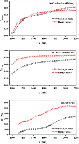 | ||
| Fig. 11 The combustion efficiency (a), total pressure loss (b), and net thrust (c) for the two modes along the streamwise location. | ||
4. Conclusions
Considering the lack of a high-fidelity ethylene skeletal mechanism suitable for combustion simulation of scramjet combustors, present work aims to obtain a compact and comprehensively validated ethylene skeletal mechanism qualified for wide combustion conditions. The static integrated skeletal reduction strategy successively consisting methods of r-DRGEP with FS scheme, improved SA and CSP importance index is performed for the hierarchically constructed NUIGMech1.2 under wide reduction conditions of temperature range of 900–1800 K, pressure range of 1–4 atm, and equivalence ratio range of 0.25–5.0. A skeletal mechanism 26S–117R with remarkably reduced size is obtained, and then it is comprehensively validated in terms of IDTs, LFSs, SCPs, AFTPs and “S”-curves. While the high-fidelity skeletal mechanism is applied to the combustion simulations of the ethylene-fueled scramjet combustor with double parallel cavities, the PFA dynamic reduction method and ISAT algorithm of TDAC is adopted to further speed up the chemical reaction solution process at run-time. Under the scramjet and the ramjet mode, the corresponding simulation results of flame luminosity images, schlieren images, and static pressure distributions, coincide well with those of experimental measurements, which further demonstrates the applicability of the skeletal mechanism derivate from the integrated reduction strategy. According to combustion efficiency, total pressure loss, and net thrust, the effects of the two modes on combustion performance are quantitatively compared, which are important for combustor design. The integrated reduction strategy and systematic kinetic verification used in present work provide reference values for the application of fuel mechanisms in scramjet combustor combustion simulation.Author contributions
Zhongwen Li: conceptualization, methodology, investigation, formalanalysis, writing – original draft. Jianwen Liu: methodology, writing – review & editing. Jingbo Wang: resources, conceptualization, funding acquisition, supervision, writing – review & editing.Conflicts of interest
There are no conflicts to declare.References
- S. P. Zeppieri, S. D. Klotz and F. L. Dryer, Proc. Combust. Inst., 2000, 28, 1587–1595 CrossRef CAS.
- Q.-D. Wang, J.-B. Wang, J.-Q. Li, N.-X. Tan and X.-Y. Li, Combust. Flame, 2011, 158, 217–226 CrossRef CAS.
- Z. Zhong, Z. Wang and M. Sun, Acta Astronaut., 2015, 110, 1–8 CrossRef CAS.
- N. Zettervall, C. Fureby and E. J. K. Nilsson, Energy Fuels, 2017, 31, 14138–14149 CrossRef CAS.
- F. Zhong, L. Cheng, H. Gu and X. Zhang, Aerosp. Sci. Technol., 2019, 86, 775–781 CrossRef.
- A. Brindle, R. Boyce and A. Neely, in AIAA/CIRA 13th International Space Planes and Hypersonics Systems and Technologies Conference, 2005, DOI:10.2514/6.2005-3239.
- G. L. Pellett, S. N. Vaden and L. G. Wilson, in 55th JANNAF Propulsion Meeting, 2008 Search PubMed.
- X. J. Fan, F. Q. Zhong, G. Yu, J. G. Li and C. J. Sung, J. Propul. Power, 2009, 25, 1226–1232 CrossRef CAS.
- K. Jackson, M. Gruber and T. Barhorst, Presented in Part at the 45th AIAA/ASME/SAE/ASEE Joint Propulsion Conference & Exhibit, Denver, Colorado, 2-5 August 2009 Search PubMed.
- Z. Zhong, Z. Wang, M. Sun and H. Wang, Proc. Inst. Mech. Eng., Part G, 2016, 230, 2515–2522 CrossRef CAS.
- K. Wu, W. Yao and X. Fan, Energy Fuels, 2017, 31, 14296–14305 CrossRef CAS.
- M. Dharavath, P. Manna and D. Chakraborty, Acta Astronaut., 2015, 117, 305–318 CrossRef CAS.
- M. Dharavath, P. Manna and D. Chakraborty, Acta Astronaut., 2016, 128, 107–118 CrossRef CAS.
- M. Mawid, B. Sekar, M. Mawid and B. Sekar, in 33rd Joint Propulsion Conference and Exhibit, 1997 Search PubMed.
- C. K. Westbrook and F. L. Dryer, Combust. Sci. Technol., 1981, 27, 31–43 CrossRef CAS.
- Z. Cai, Z. Wang, M. Sun and X.-S. Bai, in 21st AIAA International Space Planes and Hypersonics Technologies Conference, American Institute of Aeronautics and Astronautics, 2017 Search PubMed.
- T. Gao, J. Liang, M. Sun and Z. Zhong, Proc. Inst. Mech. Eng., Part G, 2017, 231, 1862–1872 CrossRef.
- M. B. Sun, Z. Zhong, T. Gao, H. Wang and J. Liang, in 21st AIAA International Space Planes and Hypersonics Technologies Conference, 2017 Search PubMed.
- J. Liu, C. J. Tam, T. Lu and C. Law, in 42nd AIAA/ASME/SAE/ASEE Joint Propulsion Conference & Exhibit, American Institute of Aeronautics and Astronautics, 2006 Search PubMed.
- C. K. Law, C. J. Sung, H. Wang and T. F. Lu, AIAA J., 2003, 41, 1629–1646 CrossRef CAS.
- A. Irannejad, A. Banaeizadeh and F. Jaberi, Combust. Flame, 2015, 162, 431–450 CrossRef CAS.
- X. Liu, Z. Cai, Y. Tong and H. Zheng, Acta Astronaut., 2017, 137, 1–7 CrossRef CAS.
- H. Wang and A. Laskin, Progress Report for an AFOSR New World Vista Program, 1998 Search PubMed.
- N. M. Marinov, W. J. Pitz, C. K. Westbrook, A. M. Vincitore, M. J. Castaldi, S. M. Senkan and C. F. Melius, Combust. Flame, 1998, 114, 192–213 CrossRef CAS.
- G. P. Smith, D. M. Golden, M. Frenklach, N. W. Moriarty, B. Eiteneer, M. Goldenberg, C. T. Bowman, R. K. Hanson, S. Song, W. C. Gardiner Jr, V. V. Lissianski and Z. Qin, GRI3.0, http://www.me.berkeley.edu/gri_mech/ Search PubMed.
- Z. Qin, V. V. Lissianski, H. Yang, W. C. Gardiner, S. G. Davis and H. Wang, Proc. Combust. Inst., 2000, 28, 1663–1669 CrossRef CAS.
- A. Konnov, Eurasian Chem.-Technol. J., 2000, 2, 257–264 CAS.
- H. Wang, X. You, A. V. Joshi, S. G. Davis, A. Laskin, F. Egolfopoulos and C. K. Law, UCS II, http://ignis.usc.edu/USC_Mech_II.htm Search PubMed.
- J. G. Lopez, C. L. Rasmussen, M. U. Alzueta, Y. Gao, P. Marshall and P. Glarborg, Proc. Combust. Inst., 2009, 32, 367–375 CrossRef CAS.
- C. Xu and A. A. Konnov, Energy, 2012, 43, 19–29 CrossRef CAS.
- E. Ranzi, A. Frassoldati, R. Grana, A. Cuoci, T. Faravelli, A. P. Kelley and C. K. Law, Prog. Energy Combust. Sci., 2012, 38, 468–501 CrossRef CAS.
- San Diego mechanism web page, University of California, at, San Diego, http://combustion.ucsd.edu Search PubMed.
- C.-W. Zhou, Y. Li, U. Burke, C. Banyon, K. P. Somers, S. Ding, S. Khan, J. W. Hargis, T. Sikes, O. Mathieu, E. L. Petersen, M. AlAbbad, A. Farooq, Y. Pan, Y. Zhang, Z. Huang, J. Lopez, Z. Loparo, S. S. Vasu and H. J. Curran, Combust. Flame, 2018, 197, 423–438 CrossRef CAS.
- M. Yang, Z. Wan, N. Tan, C. Zhang, J. Wang and X. Li, Combust. Flame, 2020, 221, 20–40 CrossRef CAS.
- M. Baigmohammadi, V. Patel, S. Martinez, S. Panigrahy, A. Ramalingam, U. Burke, K. P. Somers, K. A. Heufer, A. Pekalski and H. J. Curran, Energy Fuels, 2020, 34, 3755–3771 CrossRef CAS.
- S. S. Nagaraja, J. Liang, S. Dong, S. Panigrahy, A. Sahu, G. Kukkadapu, S. W. Wagnon, W. J. Pitz and H. J. Curran, Combust. Flame, 2020, 219, 456–466 CrossRef CAS.
- Y. Wu, S. Panigrahy, A. B. Sahu, C. Bariki, J. Beeckmann, J. Liang, A. A. E. Mohamed, S. Dong, C. Tang, H. Pitsch, Z. Huang and H. J. Curran, Combust. Flame, 2021, 226, 229–242 CrossRef CAS.
- S. Martinez, M. Baigmohammadi, V. Patel, S. Panigrahy, A. B. Sahu, S. Nagaraja, A. Ramalingam, K. A. Heufer, A. Pekalski and H. J. Curran, Combust. Flame, 2021, 234, 111626 CrossRef CAS.
- S. Dong, K. Zhang, P. K. Senecal, G. Kukkadapu, S. W. Wagnon, S. Barrett, N. Lokachari, S. Panigaphy, W. J. Pitz and H. J. Curran, Proc. Combust. Inst., 2021, 38, 611–619 CrossRef CAS.
- M. Baigmohammadi, V. Patel, S. Nagaraja, A. Ramalingam, S. Martinez, S. Panigrahy, A. A. E.-S. Mohamed, K. P. Somers, U. Burke, K. A. Heufer, A. Pekalski and H. J. Curran, Energy Fuels, 2020, 34, 8808–8823 CrossRef CAS.
- S. Martinez, M. Baigmohammadi, V. Patel, S. Panigrahy, A. B. Sahu, S. S. Nagaraja, A. Ramalingam, A. A. E.-S. Mohamed, K. P. Somers, K. A. Heufer, A. Pekalski and H. J. Curran, Combust. Flame, 2021, 228, 401–414 CrossRef CAS.
- T. Lu and C. K. Law, Prog. Energy Combust. Sci., 2009, 35, 192–215 CrossRef CAS.
- Z. Luo, C. S. Yoo, E. S. Richardson, J. H. Chen, C. K. Law and T. Lu, Combust. Flame, 2012, 159, 265–274 CrossRef CAS.
- J. Xue, S. Xi and F. Wang, Combust. Flame, 2020, 214, 184–198 CrossRef CAS.
- T. Lu and C. K. Law, Proc. Combust. Inst., 2005, 30, 1333–1341 CrossRef.
- Z. Luo, T. Lu, M. J. Maciaszek, S. Som and D. E. Longman, Energy Fuels, 2010, 24, 6283–6293 CrossRef CAS.
- P. Pepiot-Desjardins and H. Pitsch, Combust. Flame, 2008, 154, 67–81 CrossRef CAS.
- W. Sun, Z. Chen, X. Gou and Y. Ju, Combust. Flame, 2010, 157, 1298–1307 CrossRef CAS.
- Y. Wu, Y. Liu and T. Lu, Combust. Flame, 2020, 211, 303–311 CrossRef CAS.
- X. L. Zheng, T. F. Lu and C. K. Law, Proc. Combust. Inst., 2007, 31, 367–375 CrossRef.
- K. E. Niemeyer, C.-J. Sung and M. P. Raju, Combust. Flame, 2010, 157, 1760–1770 CrossRef CAS.
- R. Li, S. Li, F. Wang and X. Li, Combust. Flame, 2016, 166, 55–65 CrossRef CAS.
- S. Xi, J. Xue, F. Wang and X. Li, Combust. Flame, 2020, 222, 326–335 CrossRef CAS.
- F. Karst, M. Maestri, H. Freund and K. Sundmacher, Chem. Eng. J., 2015, 281, 981–994 CrossRef CAS.
- T. Lu and C. K. Law, Combust. Flame, 2008, 154, 153–163 CrossRef CAS.
- T. Lu and C. K. Law, J. Phys. Chem. A, 2006, 110, 13202–13208 CrossRef CAS PubMed.
- T. Løvs, D. Nilsson and F. Mauss, Proc. Combust. Inst., 2000, 28, 1809–1815 CrossRef.
- T. Lu, Y. Ju and C. K. Law, Combust. Flame, 2001, 126, 1445–1455 CrossRef CAS.
- G. Xiao, Energy Fuels, 2020, 34, 6367–6382 CrossRef CAS.
- R. Shan and T. Lu, Combust. Flame, 2012, 159, 2069–2076 CrossRef CAS.
- F. Zhong, S. Ma, X. Zhang, C.-J. Sung and K. E. Niemeyer, Acta Mech. Sin., 2015, 31, 732–740 CrossRef CAS.
- B. Liu, F. Qin and D. Cao, in 51st AIAA/SAE/ASEE Joint Propulsion Conference, 2015 Search PubMed.
- B. Liu, G.-Q. He and F. Qin, Acta Astronaut., 2018, 152, 521–533 CrossRef CAS.
- J. Li, L. Yuan, W. Li and K. Zhang, Int. J. Aerosp. Eng., 2018, 2018, 8672760 Search PubMed.
- J. He, J. Li, X. Ma, B. Meng and B. Tian, Fuel, 2023, 342, 127812 CrossRef CAS.
- F. Contino, H. Jeanmart, T. Lucchini and G. D'Errico, Proc. Combust. Inst., 2011, 33, 3057–3064 CrossRef CAS.
- Z. Li, M. T. Lewandowski, F. Contino and A. Parente, Energy Fuels, 2018, 32, 10121–10131 CrossRef CAS.
- K. Wu, F. Contino, W. Yao and X. Fan, Combust. Flame, 2018, 197, 265–275 CrossRef CAS.
- J. An, G. He, F. Qin, X. Wei and B. Liu, Combust. Flame, 2019, 206, 467–475 CrossRef CAS.
- S. B. Pope, Combust. Theory Modell., 1997, 1, 41–63 CrossRef CAS.
- L. Liang, J. G. Stevens and J. T. Farrell, Proc. Combust. Inst., 2009, 32, 527–534 CrossRef CAS.
- Y. L. Ong, F. Salehi, M. Ghiji and V. Garaniya, Combust. Theory Modell., 2021, 25, 208–234 CrossRef CAS.
- A. Storch, M. Bynum, J. Liu and M. Gruber, in 17th AIAA International Space Planes and Hypersonic Systems and Technologies Conference, 2011 Search PubMed.
- Chemkin-pro 15112, Reaction Design, San Diego, 2011 Search PubMed.
- S. H. Li, J. W. Liu, R. Li, F. Wang and X. Y. Li, Chem. J. Chin. Univ., 2015, 36, 1576–1587 CAS.
- Z. Tian, J. Li and Y. Yan, Fuel, 2019, 250, 52–64 CrossRef CAS.
- J. W. Jung, Y. C. Lim and H. K. Suh, Proc. Inst. Mech. Eng., Part D, 2020, 234, 3398–3413 CrossRef CAS.
- D. J. Micka, Combustion stabilization, structure, and spreading in a laboratory dual-mode scramjet combustor, University of Michigan, 2010 Search PubMed.
- Z. Li, J. Wang and X. Li, Fuel, 2023, 349, 128659 CrossRef CAS.
- OpenFOAM, https://openfoam.org/ Search PubMed.
- A. Kurganov and E. Tadmor, J. Comput. Phys., 2000, 160, 241–282 CrossRef CAS.
- C. J. Greenshields, H. G. Weller, L. Gasparini and J. M. Reese, Int. J. Numer. Methods Fluids, 2010, 63, 1–21 CrossRef.
- H. Zhang, M. Zhao and Z. Huang, Fuel, 2020, 282, 118812 CrossRef CAS.
- B. van Leer, J. Comput. Phys., 1974, 14, 361–370 CrossRef.
- F. Menter and T. Esch, in 16th Brazilian Congress of Mechanical Engineering (COBEM), 2001 Search PubMed.
- F. R. Menter, M. Kuntz and R. Langtry, Turbul., Heat Mass Transfer, 2003, 4, 625–632 Search PubMed.
- The OpenFOAM Foundation, kOmegaSSTBase, https://cpp.openfoam.org/v9/kOmegaSSTBase_8C_source.html Search PubMed.
- J. Chomiak and A. Karlsson, Symp. (Int.) Combust., 1996, 26, 2557–2564 CrossRef.
- L. A. Vulis, Thermal Regimes of Combustion, McGraw-Hill, 1961 Search PubMed.
- V. I. Golovitchev, N. Nordin, R. Jarnicki and J. Chomiak, SAE Trans., 2000, 109, 1391–1405 Search PubMed.
- S. Zheng, H. Liu, R. Sui, B. Zhou and Q. Lu, Combust. Flame, 2022, 235, 111699 CrossRef CAS.
- S. Zheng, Y. He, H. Liu, Y. Yang, W. Han and Q. Lu, Int. J. Hydrogen Energy, 2024, 49, 1336–1345 CrossRef CAS.
- W. Yao, Y. Lu, K. Wu, J. Wang and X. Fan, J. Propul. Power, 2018, 34, 975–991 CrossRef CAS.
- Z.-W. Huang, G.-Q. He, F. Qin and X.-G. Wei, Int. J. Hydrogen Energy, 2015, 40, 9815–9824 CrossRef CAS.
- D. J. Micka and J. F. Driscoll, Combust. Flame, 2012, 159, 1205–1214 CrossRef CAS.
- M. M. Kopp, N. S. Donato, E. L. Petersen, W. K. Metcalfe, S. M. Burke and H. J. Curran, J. Propul. Power, 2014, 30, 790–798 CrossRef CAS.
- K. Wang, R. Xu, T. Parise, J. Shao, A. Movaghar, D. J. Lee, J.-W. Park, Y. Gao, T. Lu, F. N. Egolfopoulos, D. F. Davidson, R. K. Hanson, C. T. Bowman and H. Wang, Combust. Flame, 2018, 198, 477–489 CrossRef CAS.
- O. Park, P. S. Veloo and F. N. Egolfopoulos, Proc. Combust. Inst., 2013, 34, 711–718 CrossRef CAS.
- G. Jomaas, X. L. Zheng, D. L. Zhu and C. K. Law, Proc. Combust. Inst., 2005, 30, 193–200 CrossRef.
- T. Hirasawa, C. J. Sung, A. Joshi, Z. Yang, H. Wang and C. K. Law, Proc. Combust. Inst., 2002, 29, 1427–1434 CrossRef CAS.
- F. N. Egolfopoulos, D. L. Zhu and C. K. Law, Symp. (Int.) Combust., 1991, 23, 471–478 CrossRef.
- M. I. Hassan, K. T. Aung, O. C. Kwon and G. M. Faeth, J. Propul. Power, 1998, 14, 479–488 CrossRef CAS.
- K. Kumar, G. Mittal, C.-J. Sung and C. K. Law, Combust. Flame, 2008, 153, 343–354 CrossRef CAS.
- S. Jallais, L. Bonneau, M. Auzanneau, V. Naudet and S. Bockel-Macal, Ind. Eng. Chem. Res., 2002, 41, 5659–5667 CrossRef CAS.
- M. Aliyu, A. Abdelhafez, M. A. Nemitallah, S. A. M. Said and M. A. Habib, Energy, 2022, 243, 123077 CrossRef CAS.
- A. Abdelhafez, M. A. Nemitallah, S. S. Rashwan and M. A. Habib, Energy Fuels, 2018, 32, 7868–7877 CrossRef CAS.
- Y. Tian, S. Yang, J. Le, T. Su, M. Yue, F. Zhong and X. Tian, Int. J. Hydrogen Energy, 2016, 41, 19218–19230 CrossRef CAS.
- D. J. Micka and J. F. Driscoll, Proc. Combust. Inst., 2009, 32, 2397–2404 CrossRef CAS.
- H. Wang, Z. Wang, M. Sun and H. Wu, Int. J. Hydrogen Energy, 2013, 38, 12078–12089 CrossRef CAS.
- T. Kouchi, C. P. Goyne, R. D. Rockwell and J. C. McDaniel, Exp. Fluids, 2015, 56, 211 CrossRef.
Footnote |
| † Electronic supplementary information (ESI) available. See DOI: https://doi.org/10.1039/d4ra00749b |
| This journal is © The Royal Society of Chemistry 2024 |

