 Open Access Article
Cellulose/silica composite microtubular superfoam with excellent flame retardancy, thermal insulation and ablative resistance†
Ding Han,
Xiankai Sun *,
Shichao Zhang,
Linghao Wu,
Bing Ai,
Haoran Sun and
Yufeng Chen
China Building Materials Academy Co., Ltd, No.1 Guan Zhuang Dong Li, Chaoyang District, Beijing, 100024, P. R. China. E-mail: sunxiankai2008@163.com; tjuhd@163.com; zhangshichao@cbma.com.cn; 16116339@bjtu.edu.cn; aibing2018@163.com; moto398@126.com; chenyunfeng@tom.com; Tel: +86 010-51167551
First published on 22nd April 2024
Abstract
Thermal insulation materials with good flame-retardant properties have attracted widespread attention because of their huge application potential. Traditional petrochemical-based polymer insulation materials are flammable and have problems with environmental pollution. The microtubule structure is a perfect microstructure with excellent thermal insulation performance. In addition, the microtubule structure also has low density and high elasticity. Therefore, the microtubule structure is an important reference microstructure for the development of efficient thermal insulation materials. In this paper, a cellulose/SiO2 composite microtube thermal insulation superfoam has been successfully prepared. Cellulose microtubules were successfully prepared from poplar sawdust by chemical methods. The SiO2 aerogel precursor solution can be quickly adsorbed by the delignified cellulose microtubes. The SiO2 aerogel shells are evenly distributed only on the inner and outer walls of the delignified cellulose microtubes. The cellulose/SiO2 microtube composite (CSMC) superfoam exhibits low density, good mechanical properties, and low thermal conductivity (as low as 0.042 ± 0.0018 W m−1 K−1). The CSMC superfoam exhibits excellent self-extinguishing and flame-retardant properties. After being burned by a butane flame, the superfoam still has certain mechanical properties. The thermal conductivity of the B-CSMC superfoam (the CSMC superfoam burned by a butane flame) is about 0.050 W m−1 K−1. The B-CSMC superfoam remained almost unchanged after being continuously ablated by a butane flame for 3600 seconds.
1. Introduction
In recent years, thermal insulation materials with excellent flame-retardant properties have attracted wide attention due to their huge application potential in the fields of construction and transportation.1,2 Generally, thermal insulation materials used in construction and transportation are currently dominated by petrochemical polymer-based thermal insulation materials.3,4 These petrochemical-based polymer thermal insulation materials are flammable organic materials, which can easily cause fire accidents and cause huge losses.5 In addition, the widespread use of petrochemical polymer-based thermal insulation materials will lead to serious environmental problems and cause white pollution.6 To solve these problems, the development of sustainable and environmentally friendly thermal insulation materials with better flame-retardant properties has attracted widespread attention.The long-term evolution of biological structures shows that the microtubule structure is a perfect microstructure with excellent thermal insulation performance.7,8 First, the air in the microtube structure has a lower thermal conductivity than the solid material, and the microtube structure can effectively prevent heat conduction.9,10 Second, the microtubule structure can also provide lightweight properties. The structure of a microtubule is usually composed of thin tube walls, so the microtubule structure generally has a lower density. This allows the microtubule structure to achieve the same thermal insulation effect while having a lighter mass.11,12 In addition, the microtubule structure can also provide better elasticity and durability.13,14 The special structure of microtubules endows them with a certain ability to bend and deform, and to resist external shocks and pressures. Therefore, the microtubule structure is an important reference microstructure for the development of high-efficiency thermal insulation materials.
Cellulose is a very abundant renewable natural biomass material, which is the main component of the tubular microstructure of wood.15 A slender cellulose microtube can be easily exfoliated from natural wood using a simple chemical delignification method.16–18 The slender cellulose microtubules are composed of microfibers that are spirally wound at different angles.19,20 A spindle-like pore structure appears between the spiral wound microfibers due to the removal of lignin.21 The porous cellulose microtubules still exhibit good mechanical properties due to the multi-scale hydrogen bond interface of the cellulose microfibers.22,23 In addition, the surface chemical environment with abundant hydroxyl and oxygen atoms is helpful to further regulate the properties of the slender cellulose microtubules by different physical or chemical methods.24,25 This is conducive to the preparation of porous natural cellulose microtubule composites with excellent thermal insulation properties. However, due to the inherent flammability of cellulose, the widespread application of cellulose microtubule thermal insulation materials in construction and transportation is greatly limited. It is found that the introduction of inorganic materials into cellulose-based thermal insulation materials can significantly improve their flame retardancy.26–28 These introduced inorganic materials (such as hydroxyapatite, montmorillonite, or exfoliated clay) have high fire-resistance properties, which can inhibit the combustion and flame spread of cellulosic materials, and thus improve the flame-retardant performance of cellulose insulation materials.29–32 However, the poor compatibility between inorganic fillers and polymers will weaken the interaction between inorganic fillers and polymer interface, and the dispersion of fillers in the polymers will also be affected.33 Therefore, the addition of inorganic materials (usually in the form of inorganic fillers) will not only reduce the strength of the composite material, but also prevent the flame-retardant performance of the composite insulation material from being significantly improved. In fact, the controlled introduction of inorganic materials in different states into polymer materials can simultaneously improve the thermal insulation, flame retardancy and even the mechanical properties of composite materials.34 Therefore, cellulose microtubule composites with excellent thermal insulation, flame retardance and mechanical properties can be prepared by introducing inorganic materials into cellulose microtubules.
In this study, we are committed to using green and low-carbon processes for the preparation of thermal protection materials. CSMC-X superfoam was prepared by vacuum filtration of cellulose microtubes saturated with adsorbed SiO2 aerogel precursor solution. The SiO2 aerogel shell is evenly distributed only on the inner and outer walls of the delignified cellulose microtubes. The CSMC-X superfoam exhibits a low density, good mechanical properties, low thermal conductivity, and good flame-retardant properties. The CSMC-X superfoam after butane flame calcination still exhibits certain mechanical properties.
2. Experimental section
2.1 Preparation of the delignified cellulose microtubes
About 10 g of poplar sawdust was added to 500 mL of sodium chlorite solution (5%, pH 4–5, adjusted by adding acetic acid), and the resulting mixed solution was heated and stirred at 95 °C in an oil bath for about 12 h.35 After several washes with deionized water to remove residual chemicals, the delignified cellulose microtube was obtained after freeze-drying.2.2 Preparation of the cellulose/SiO2 microtube composite thermal insulation superfoam
Tetraethyl orthosilicate (TEOS) was added to a mixed solution of ethanol and water (the pH of the mixed solution was adjusted with 0.5 M oxalic acid solution; the molar ratios of tetraethyl orthosilicate, ethanol, and water were 1![[thin space (1/6-em)]](https://www.rsc.org/images/entities/char_2009.gif) :
:![[thin space (1/6-em)]](https://www.rsc.org/images/entities/char_2009.gif) 1
1![[thin space (1/6-em)]](https://www.rsc.org/images/entities/char_2009.gif) :
:![[thin space (1/6-em)]](https://www.rsc.org/images/entities/char_2009.gif) 4, 1
4, 1![[thin space (1/6-em)]](https://www.rsc.org/images/entities/char_2009.gif) :
:![[thin space (1/6-em)]](https://www.rsc.org/images/entities/char_2009.gif) 2.5
2.5![[thin space (1/6-em)]](https://www.rsc.org/images/entities/char_2009.gif) :
:![[thin space (1/6-em)]](https://www.rsc.org/images/entities/char_2009.gif) 4, 1
4, 1![[thin space (1/6-em)]](https://www.rsc.org/images/entities/char_2009.gif) :
:![[thin space (1/6-em)]](https://www.rsc.org/images/entities/char_2009.gif) 5
5![[thin space (1/6-em)]](https://www.rsc.org/images/entities/char_2009.gif) :
:![[thin space (1/6-em)]](https://www.rsc.org/images/entities/char_2009.gif) 4, and 1
4, and 1![[thin space (1/6-em)]](https://www.rsc.org/images/entities/char_2009.gif) :
:![[thin space (1/6-em)]](https://www.rsc.org/images/entities/char_2009.gif) 10
10![[thin space (1/6-em)]](https://www.rsc.org/images/entities/char_2009.gif) :
:![[thin space (1/6-em)]](https://www.rsc.org/images/entities/char_2009.gif) 4, respectively), and hydrolysed for about 7 hours to obtain a mixed hydrolysis solution (50 g). 0.5 g of cellulose microtubes were added to the above mixed hydrolysis solution (50 g), and stirred for 1 min. Then, the cellulose microtubes that evenly adsorb mixed hydrolysates were filtered with a Büchner funnel for about 6 min (the excess mixed hydrolysates absorbed by the cellulose microtubes were completely removed). The obtained cellulose microtubule composite material adsorbing TEOS hydrolysate was placed in a closed area and left to stand overnight (the TEOS hydrolysate undergoes polycondensation to form SiO2 hydrogel shells). The obtained cellulose/SiO2 microtubules composite superfoam material was aged in ethanol for 24 hours. It was replaced twice with a solution of n-hexane and dried at 80 °C for 6 hours. Finally, the cellulose/SiO2 microtube composite superfoam materials were prepared. A butane spray gun was adjusted to the maximum blue flame. B-CSMC superfoam was obtained by moving the blue flame to ablate the surface of the cellulose/SiO2 microtubule composite superfoam material continuously and uniformly for 5 minutes. The fabrication process of the B-CSMC superfoam material is illustrated in Fig. 1.
4, respectively), and hydrolysed for about 7 hours to obtain a mixed hydrolysis solution (50 g). 0.5 g of cellulose microtubes were added to the above mixed hydrolysis solution (50 g), and stirred for 1 min. Then, the cellulose microtubes that evenly adsorb mixed hydrolysates were filtered with a Büchner funnel for about 6 min (the excess mixed hydrolysates absorbed by the cellulose microtubes were completely removed). The obtained cellulose microtubule composite material adsorbing TEOS hydrolysate was placed in a closed area and left to stand overnight (the TEOS hydrolysate undergoes polycondensation to form SiO2 hydrogel shells). The obtained cellulose/SiO2 microtubules composite superfoam material was aged in ethanol for 24 hours. It was replaced twice with a solution of n-hexane and dried at 80 °C for 6 hours. Finally, the cellulose/SiO2 microtube composite superfoam materials were prepared. A butane spray gun was adjusted to the maximum blue flame. B-CSMC superfoam was obtained by moving the blue flame to ablate the surface of the cellulose/SiO2 microtubule composite superfoam material continuously and uniformly for 5 minutes. The fabrication process of the B-CSMC superfoam material is illustrated in Fig. 1.
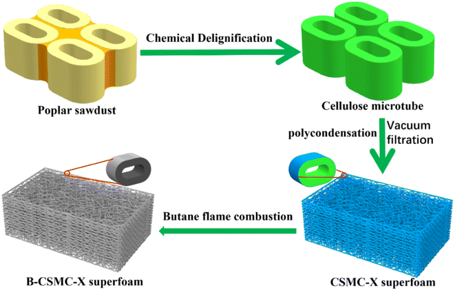 | ||
| Fig. 1 Illustration of fabrication process for the flame-retardant CSMC-X thermal insulation superfoam. | ||
2.3 Material characterization
The morphologies of the samples were characterized using field emission scanning electron microscopy (SEM, JSM-6490LV, Japan) with energy dispersive X-ray spectroscopy (Noran System 7) at 3 kV accelerating voltage. The samples were prepared as follows: the samples were placed on conductive tape and processed with gold spraying for about 240 s.The X-ray diffraction (XRD) patterns of the samples were characterized on a D8 ADVANCE (Germany) instrument with Cu (λ = 0.1541 nm) Kα irradiation (30 mA and 40 kV, in the 2θ range from 5° to 80° with a scan rate of 0.04°·s−1). The samples were prepared as follows: the crushed sample was placed directly into the groove of the test stand, and the sample in the groove was pressed into a flat surface.
The Raman spectra of the samples were investigated on a HORIBA Scientific LabRAM HR Evolution Raman spectrometer (laser wavelength of 532 nm, 600 line per mm grating, scanned 3 times, for 5 s each time). The samples were prepared as follows: the sample was placed on a slide and pressed into a flat surface with the slide. The baseline of the Raman spectra was not corrected using software correction.
The X-ray photoelectron spectra of the samples were performed on a ESCALAB 250Xi (USA, monochromatic Al Ka source with 0.1 eV resolution). The samples were prepared as follows: the sample was pressed directly onto double-sided tape, and then the double-sided tape with the sample was directly adhered to the sample stage. The wide-range scans were performed once; the XPS spectra of C, O and Si were scanned five times.
The N2 sorption measurements of the samples (the sample was degassed at 120 °C for 12 h.) were collected in a BELSORP-mini II instrument (Japan) under nitrogen conditions (at 77 K). The pore size distribution of the composite foams was determined using the Barrett–Joyner–Halenda (BJH) method.36
The compressive strength of the samples was evaluated in a UTM2501 (China) with a loading rate of 2 mm min−1 (the ratio of height to diameter of the cylindrical composite foam was approximately 0.24, 1000 N load cell at room temperature).
The thermal degradation properties of the samples (the samples were dried in a vacuum oven at 100 °C for 24 h) were studied from 50 to 800 °C under an N2 atmosphere with a heating rate of 5 °C min−1.
The Fourier transform infrared (FT-IR) spectra of the samples were performed in a BRUKER TENSOR 27 FT–IR Spectrometer. The samples were analysed by transmission spectra in the region between 4000 and 400 cm−1, with 32 scans at 4 cm−1 resolution. The baseline of the FT-IR spectra was corrected using software correction. The samples were prepared as follows: the samples were dried in a vacuum oven at 80 °C for 24 h. About 1 mg of dried sample and about 100 mg of KBr were ground in a mortar, and the mixture was transferred to a mold and pressed into a round sheet.
The thermal conductivity of the sample was measured on a DRE-III thermal conductivity meter (Xiangtan Instrument Co., Ltd Xiangtan, China; the output power was 0.1 W, the test time was 160 s, the sampling interval was 1000 ms, the probe resistance was 16.7 Ω, the probe radius was 7.5 mm, and the probe thickness was 0.2 mm) at room temperature. The samples were used directly to test the thermal conductivity, and the sensor was directly sandwiched between the two sample planes.
The adsorption of the SiO2 aerogel precursor solutions by cellulose microtubules was observed using an optical microscope (XZJ-2023B, PHENIX, China) at room temperature. The sample was placed on a slide and then covered with a cover slide. Focus imaging was performed under a 5× objective lens using a CCD camera. Then the SiO2 aerogel precursor solution was dropped onto the edge of the cover glass, and the image was re-focused under a 5× objective lens. The process of adsorption of SiO2 aerogel precursor solution by cellulose microtubules was observed under an objective lens with appropriate magnification.
3. Results and discussion
3.1 Structural and morphological analysis of the delignified cellulose microtubes
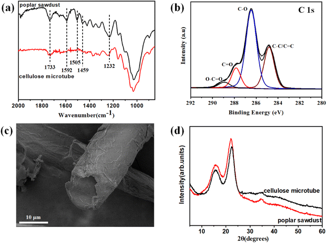
The average removal percentage after delignification with sodium chlorite is as high as 41.8 ± 1.5% (significantly higher than the 20–30 wt% lignin content in wood). This indicates that high-efficiency removal of lignin and partial hemicellulose can be achieved using sodium chlorite. The characteristic lignin bands at 1232 cm−1 (C–O groups in lignin and hemicellulose), 1459 cm−1 (aromatic skeletal vibrations), 1505 cm−1 (aromatic skeletal vibrations), 1592 cm−1 (aromatic skeletal vibrations), and 1732 cm−1 (C![[double bond, length as m-dash]](https://www.rsc.org/images/entities/char_e001.gif) O stretching in unconjugated ketone) tended to be weaker and even disappeared after delignification. This indicates that the lignin had been almost completely removed (Fig. 2a).37,38 High-resolution C 1s spectra of the poplar sawdust and cellulose microtubes (Fig. 2b and S1†), showed that the relative percentage of C–C/C
O stretching in unconjugated ketone) tended to be weaker and even disappeared after delignification. This indicates that the lignin had been almost completely removed (Fig. 2a).37,38 High-resolution C 1s spectra of the poplar sawdust and cellulose microtubes (Fig. 2b and S1†), showed that the relative percentage of C–C/C![[double bond, length as m-dash]](https://www.rsc.org/images/entities/char_e001.gif) C peak at 284.8 eV decreased significantly from about 41.9% of the poplar sawdust to about 28.2% of the cellulose microtubes after delignification. Lignin is a polymer composed of phenylpropane units. When the lignin is removed by sodium chlorite, the proportion of the C–C/C
C peak at 284.8 eV decreased significantly from about 41.9% of the poplar sawdust to about 28.2% of the cellulose microtubes after delignification. Lignin is a polymer composed of phenylpropane units. When the lignin is removed by sodium chlorite, the proportion of the C–C/C![[double bond, length as m-dash]](https://www.rsc.org/images/entities/char_e001.gif) C peak will become significantly smaller. This further proves that the lignin in the wood tubes was effectively removed. The efficient removal of lignin and partial hemicellulose promoted the efficient separation of elongated wood cells. Furthermore, many microporous structures appeared in the delignified cellulose microtube after delignification. Correspondingly, the total pore volume increased from 0.0040 cm3 g−1 (poplar sawdust) to 0.0083 cm3 g−1 (the delignified cellulose microtubes, Table S1 and Fig. S2†). Compared with poplar sawdust (approximately 2.9 m2 g−1), the Brunauer–Emmett–Teller (BET) specific surface area of the delignified cellulose microtubes is significantly larger (approximately 4.8 m2 g−1). The abundant micropore structure and large specific surface area are conducive to increasing the tight adsorption capacity of SiO2 aerogel precursor solution by delignified cellulose microtubules. The diameter of the delignified cellulose microtubes is about 10 μm, and the length can even reach the centimeter scale (Fig. 2c and S3†). The XRD spectra of the delignified cellulose microtubes show two broad diffraction peaks at about 15.5° and 22.3° (Fig. 2d). The peak at about 15.5° is assigned to the (1
C peak will become significantly smaller. This further proves that the lignin in the wood tubes was effectively removed. The efficient removal of lignin and partial hemicellulose promoted the efficient separation of elongated wood cells. Furthermore, many microporous structures appeared in the delignified cellulose microtube after delignification. Correspondingly, the total pore volume increased from 0.0040 cm3 g−1 (poplar sawdust) to 0.0083 cm3 g−1 (the delignified cellulose microtubes, Table S1 and Fig. S2†). Compared with poplar sawdust (approximately 2.9 m2 g−1), the Brunauer–Emmett–Teller (BET) specific surface area of the delignified cellulose microtubes is significantly larger (approximately 4.8 m2 g−1). The abundant micropore structure and large specific surface area are conducive to increasing the tight adsorption capacity of SiO2 aerogel precursor solution by delignified cellulose microtubules. The diameter of the delignified cellulose microtubes is about 10 μm, and the length can even reach the centimeter scale (Fig. 2c and S3†). The XRD spectra of the delignified cellulose microtubes show two broad diffraction peaks at about 15.5° and 22.3° (Fig. 2d). The peak at about 15.5° is assigned to the (1![[1 with combining macron]](https://www.rsc.org/images/entities/char_0031_0304.gif) 0)/(110) planes of the cellulose I crystalline structure, and the peak at about 22.3° is assigned to the (200) planes of the cellulose I crystalline structure.39 This indicates that the obtained delignified cellulose microtube possess a typical cellulose I crystal structure.
0)/(110) planes of the cellulose I crystalline structure, and the peak at about 22.3° is assigned to the (200) planes of the cellulose I crystalline structure.39 This indicates that the obtained delignified cellulose microtube possess a typical cellulose I crystal structure.
3.2 The adsorption ability of the delignified cellulose microtube for the SiO2 aerogel precursor solution
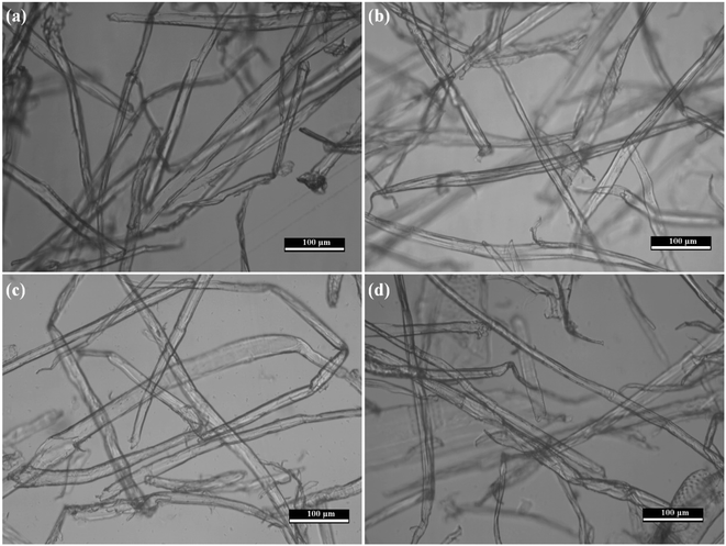
The SiO2 aerogel precursor solution can be quickly adsorbed by the delignified cellulose microtubes, so that a certain number of tubular bubbles appeared in the delignified cellulose microtubes at the beginning of adsorption (Fig. S4†). The tubular bubbles gradually disappeared as the SiO2 aerogel precursor solution was gradually adsorbed by the delignified cellulose microtubes due to the good wettability (between the delignified cellulose microtubes and the precursor solution) and the abundant microporous structures of the delignified cellulose microtubes (Fig. 3). The delignified cellulose microtubes that adsorbed different concentrations of SiO2 aerogel precursor solution were all in a saturated state. The saturation adsorption capacities of the delignified cellulose microtubes were 3.39 ± 0.05 (CSMC-1.0), 3.06 ± 0.42 (CSMC-2.5), 2.34 ± 0.25 (CSMC-5.0) and 1.83 ± 0.35 g (CSMC-10.0) (the mass of the delignified cellulose microtubes was about 0.5 g, the saturation adsorption capacity of cellulose microtubules was measured by subtracting the mass of cellulose microtubules from the mass of the wet foam of cellulose microtubules after adsorption, Fig. S5†). The mass of the SiO2 aerogel precursor solution adsorbed by the delignified cellulose microtubes gradually increases with an increase in TEOS.3.3 Morphological and structural analysis of the CSMC-X superfoam
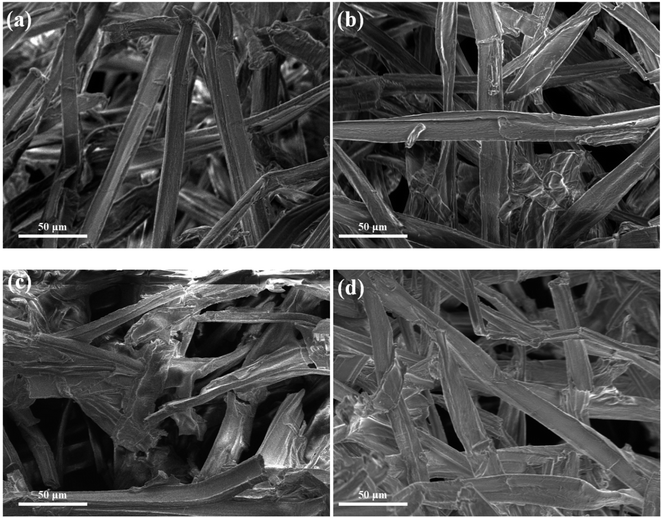
The SiO2 aerogel shells are uniformly distributed only on the inner and outer walls of the delignified cellulose microtubes. Bulk SiO2 aerogels were not found in the delignified cellulose microtubes or between the delignified cellulose microtubes (Fig. 4a–d and S6†). Furthermore, the cellulose/SiO2 aerogel microtubes still have the structural and morphological characteristics of the delignified cellulose microtube. This indicates that the vacuum filtration process can not only remove the SiO2 aerogel precursor solution in the cellulose microtubules and between the cellulose microtubules, but also remove the SiO2 aerogel precursor solution that is not tightly bound to the cellulose microtubules on the inner and outer surfaces of the delignified cellulose microtube. Only the SiO2 aerogel precursor solution tightly bound to the delignified cellulose microtube remained on the inner and outer surfaces of the cellulose microtubules. There seems to be no significant difference in the thickness of the SiO2 aerogel shell among the different composites (Fig. S7†). This may be because the concentration of the SiO2 precursor solution has limited influence on the thickness of the SiO2 precursor solution (which is tightly bound to the cellulose microtubules). The thickness of the tightly bound SiO2 precursor solution may be related mainly to the surface properties of the cellulose microtubules. However, with an increase in the concentration of the SiO2 aerogel precursor solution, the morphology of the SiO2 aerogel shell on the surface of the delignified cellulose microtube also changed obviously (Fig. S8†). The SiO2 aerogel shell of the delignified cellulose microtube became apparently denser with an increase in the concentration of the SiO2 aerogel precursor solution.Fig. 5a–d show the energy dispersive X-ray spectroscopy (EDS) element mapping patterns of the CSMC-5.0 superfoam. The EDS element mapping patterns reveal that the C (yellow), O (red) and Si (yellow) elements are uniformly distributed throughout the composite cellulose/SiO2 microtubules.
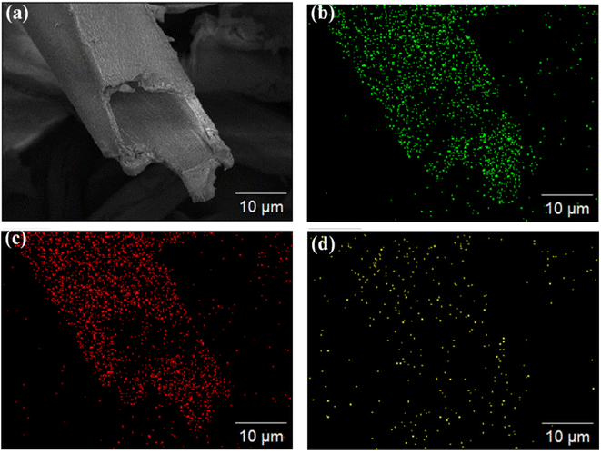 | ||
| Fig. 5 Microtubule structure of the CSMC-2.5 superfoam (a) and its corresponding EDS elemental mappings of C (b), O (c), and Si (d). | ||
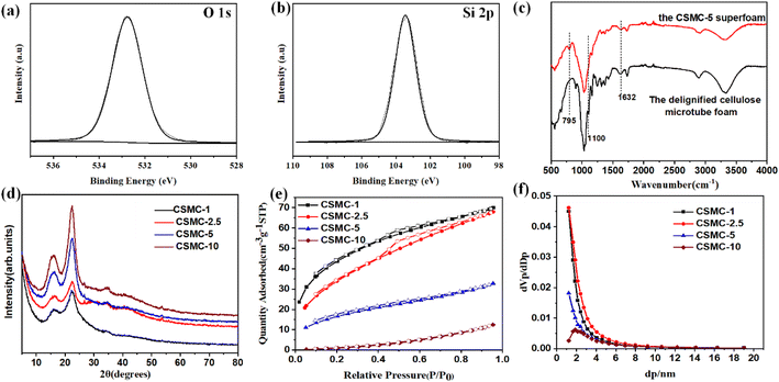
To investigate the surface chemical environment of the cellulose/SiO2 composite microtubes, the CSMC-5.0 superfoam was further characterized by X-ray photoelectron spectroscopy (XPS). Fig. 6a and b show the high-resolution O 1s and Si 2p, respectively (calibrated by the peak of C 1s with a standard binding energy of 284.8 eV). Obviously, both the high-resolution Si 2p and O 1s high-resolution peaks of the CSMC-5.0 superfoam can be deconvoluted into a symmetric single peak (centered at 103.45 eV for Si 2p and centered at 532.77 for O 1s). Therefore, this demonstrates that the Si element on the surface of the composite microtube has only one chemical structure of Si oxidation state Si4+.40 On the other hand, the O 1s spectrum with the same single peak characteristic indicates that the O element also has only one chemical structure (O–Si). The results of XPS data analysis show that the surface of a cellulose/SiO2 composite microtube is evenly covered with an SiO2 aerogel shell. The interaction between SiO2 aerogel shells and cellulose microtubules was evaluated by infrared spectroscopy.41 The absorption band at about 795 cm−1 in the infrared spectrum of the CSMC-5 superfoam is the Si–O–Si stretching vibration band (Fig. 6c). The absorption band at about 1100 cm−1 in the infrared spectrum of the CSMC-5 superfoam is the Si–O–C stretching vibration band, and the stretching vibration band of the C–O bond in cellulose is covered by the Si–O–C stretching vibration band due to the molar extinction coefficient of the stretching vibration of the C–O bond being lower than the Si–O band by about 4–5 orders of magnitude. The infrared results indicated that the SiO2 aerogel shell is combined with cellulose microtubules. Compared with the delignified cellulose microtube, a weaker absorption band at 1632 cm−1 (the absorption band of the O–H bending vibration for the absorbed water) indicated that the hydrophilicity of the CSMC-5 superfoam had been weakened. The crystal structure of the CSMC-X superfoam was characterized by XRD analysis. Fig. 6d shows the XRD spectrum of the CSMC-X superfoam. The patterns of the CSMC-X superfoam exhibit two broad diffraction peaks at about 2θ = 15.7° and at around 2θ = 27.4°, which can be assigned to the (1![[1 with combining macron]](https://www.rsc.org/images/entities/char_0031_0304.gif) 0), (110) and (200) characteristic diffraction peaks of the cellulose I crystal structure. It can be seen that only the characteristic diffraction peaks of the cellulose I crystal structure are present in the spectra, while the characteristic diffraction peaks of the SiO2 aerogel are not observed. The results of the XRD analysis indicated that the SiO2 aerogel shell on the inner and outer surface of the cellulose microtubules has an amorphous structure. The pore structure of the CSMC-X superfoam, especially the SiO2 aerogel shell, was evaluated by analysis of the nitrogen adsorption/desorption isotherms. Fig. 6e and f show the N2 absorption/desorption isotherms and pore size distribution curves of the CSMC-X superfoam (the relevant pore structure data are summarized in Table S2†). According to the IUPAC classification, the N2 absorption/desorption isotherm of the CSMC-10 superfoam is a typical type-III adsorption/desorption isotherm curve, which indicates that the CSMC-10 superfoam consists mainly of macropores.42 With an increase in the concentration of SiO2 precursor solution, the type of the N2 absorption/desorption isotherm gradually transforms from a type-III adsorption/desorption isotherm curve to a type-I adsorption/desorption isotherm curve (with a type H4 hysteresis loop) due to the stronger interaction between N2 and SiO2 aerogel than that between N2 and delignified cellulose microtubes. The type-I adsorption/desorption isotherm curve with a type H4 hysteresis loop indicates that there are many micropores in the SiO2 aerogel shell of the CSMC-2.5 and CSMC-1 superfoams. The BET specific surface areas of CSMC-1, CSMC-2.5, CSMC-5 and CSMC-10 superfoams are 159, 120, 57 and 7 m2 g−1, respectively. The BET specific surface area of the CSMC-X superfoam increases significantly with an increase in the concentration of the SiO2 aerogel precursor solution. This phenomenon shows that the pore structure of the CSMC-X superfoam is derived mainly from the SiO2 aerogel shell on the inner and outer surfaces of the cellulose microtubules. Obviously, the percentage of N2 absorption/desorption originating from the SiO2 aerogel shell gradually increases with an increase in the concentration of the SiO2 aerogel precursor solution. The average pore size of the CSMC superfoam decreases with an increase in the concentration of SiO2 aerogel precursors. The average pore sizes of CSMC-1, CSMC-2.5, CSMC-5 and CSMC-10 superfoam are 2.7, 3.4, 3.5 and 10.9 nm, respectively. The total pore volume are 0.1081 (CSMC-1 superfoam), 0.1051 (CSMC-2.5 superfoam), 0.0507 (CSMC-5 superfoam), and 0.0193 (CSMC-10 superfoam). The results of the N2 absorption/desorption isotherm analysis indicated that the pore structure of the SiO2 aerogel shell on the inner and outer surfaces of the cellulose microtubules can be efficiently regulated by the concentration of the SiO2 aerogel precursor.
0), (110) and (200) characteristic diffraction peaks of the cellulose I crystal structure. It can be seen that only the characteristic diffraction peaks of the cellulose I crystal structure are present in the spectra, while the characteristic diffraction peaks of the SiO2 aerogel are not observed. The results of the XRD analysis indicated that the SiO2 aerogel shell on the inner and outer surface of the cellulose microtubules has an amorphous structure. The pore structure of the CSMC-X superfoam, especially the SiO2 aerogel shell, was evaluated by analysis of the nitrogen adsorption/desorption isotherms. Fig. 6e and f show the N2 absorption/desorption isotherms and pore size distribution curves of the CSMC-X superfoam (the relevant pore structure data are summarized in Table S2†). According to the IUPAC classification, the N2 absorption/desorption isotherm of the CSMC-10 superfoam is a typical type-III adsorption/desorption isotherm curve, which indicates that the CSMC-10 superfoam consists mainly of macropores.42 With an increase in the concentration of SiO2 precursor solution, the type of the N2 absorption/desorption isotherm gradually transforms from a type-III adsorption/desorption isotherm curve to a type-I adsorption/desorption isotherm curve (with a type H4 hysteresis loop) due to the stronger interaction between N2 and SiO2 aerogel than that between N2 and delignified cellulose microtubes. The type-I adsorption/desorption isotherm curve with a type H4 hysteresis loop indicates that there are many micropores in the SiO2 aerogel shell of the CSMC-2.5 and CSMC-1 superfoams. The BET specific surface areas of CSMC-1, CSMC-2.5, CSMC-5 and CSMC-10 superfoams are 159, 120, 57 and 7 m2 g−1, respectively. The BET specific surface area of the CSMC-X superfoam increases significantly with an increase in the concentration of the SiO2 aerogel precursor solution. This phenomenon shows that the pore structure of the CSMC-X superfoam is derived mainly from the SiO2 aerogel shell on the inner and outer surfaces of the cellulose microtubules. Obviously, the percentage of N2 absorption/desorption originating from the SiO2 aerogel shell gradually increases with an increase in the concentration of the SiO2 aerogel precursor solution. The average pore size of the CSMC superfoam decreases with an increase in the concentration of SiO2 aerogel precursors. The average pore sizes of CSMC-1, CSMC-2.5, CSMC-5 and CSMC-10 superfoam are 2.7, 3.4, 3.5 and 10.9 nm, respectively. The total pore volume are 0.1081 (CSMC-1 superfoam), 0.1051 (CSMC-2.5 superfoam), 0.0507 (CSMC-5 superfoam), and 0.0193 (CSMC-10 superfoam). The results of the N2 absorption/desorption isotherm analysis indicated that the pore structure of the SiO2 aerogel shell on the inner and outer surfaces of the cellulose microtubules can be efficiently regulated by the concentration of the SiO2 aerogel precursor.
The compressive strength of the CSMC superfoams increased from 63 kPa for the CSMC-10 superfoam to 366 kPa for the CSMC-1 superfoam under a strain of 60% (the monolithic cellulose microtubular foam cannot be obtained using hexane, Fig. 7a). The CSMC-5.0 superfoam could withstand about 1005 times its own mass without deformation, indicating superior mechanical robustness (Fig. S9†). This indicates that the controlled introduction of SiO2 aerogel shells on the inner and outer walls of the delignified cellulose microtubes can significantly enhance the structure of the CSMC superfoams and improve the mechanical properties of the CSMC superfoams. The densities of the CSMC-10, CSMC-5, CSMC-2.5, and CSMC-1 superfoams were 44.7 ± 2.3, 58.4 ± 3.0, 69.5 ± 7.7, and 77.5 ± 8.7 kg m−3, respectively (Fig. 7b). The CSMC superfoam exhibits a lower density. Such a low density of the CSMC superfoam may be derived from its unique composite microtubule structure. With an increase in the concentration of SiO2 aerogel precursor, the density of the CSMC superfoam gradually increases, indicating that the SiO2 aerogel shell has a significant effect on the density of the CSMC superfoam. The CSMC superfoams exhibit excellent mechanical performance while possessing low densities.
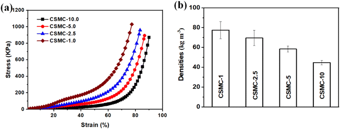 | ||
| Fig. 7 The mechanical strength of the CSMC-X superfoam (a). The density of the CSMC-X superfoam (b). | ||
3.4 Thermal insulation, flame retardant and ablative properties of the CSMC-X superfoam
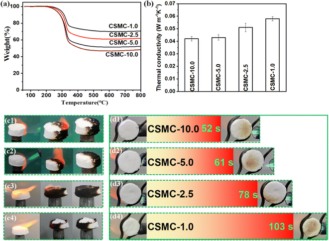
The thermal stability of the CSMC-X superfoam was determined by thermogravimetric techniques. The thermogravimetric data of the CSMC-X superfoam is shown in Fig. 8a. It is obvious that the CSMC-X superfoam showed a one-step thermal decomposition process in nitrogen, related to the thermal degradation of cellulose microtubules over the range of 200–345 °C.43 The decomposition temperature of the CSMC-X superfoam gradually increases from 289 °C (CSMC-10.0 superfoam) to 311 °C (CSMC-1.0 superfoam) with an increase in the concentration of the SiO2 precursor solution. On the other hand, the residue of CSMC-X superfoam gradually increases from approximately 48% (CSMC-10.0 superfoam) to approximately 70% (CSMC-1.0 superfoam) at a carbonization temperature of 800 °C. The above results indicate that the SiO2 aerogel shell on the surface of cellulose microtubules leads to higher thermal stability and residue of the CSMC-X superfoam. The thermal conductivity of the CSMC-X superfoam gradually decreases as the concentration of the SiO2 aerogel precursor decreases, and the thermal conductivity of the CSMC-10.0 superfoam is as low as 0.042 ± 0.0018 W m−1 K−1 (Fig. 8b). Compared to the cellulose-based foams developed by other research groups, the CSMC-X superfoam exhibits lower density and smaller thermal conductivity (Table 1). This indicates that the hollow microtubule structure has excellent structural advantages in the field of high-performance lightweight thermal insulation materials.| Material | Drying method | ρ (kg m−3) | λ (W m−1 K−1) | Reference |
|---|---|---|---|---|
| Rice straw fibers/PVA | Freeze-drying | 50–60 | 0.034–0.036 | 44 |
| Silica/cellulose | Freeze-drying | 55–60 | 0.023 | 45 |
| Kapok fiber/MMT | Ambient drying | 41 | 0.054 | 46 |
| Bamboo fiber/cellulose | Thermal drying | 160 | 0.054 | 47 |
| Pulp fibers/clay | Thermal drying | 136 | 0.043 | 48 |
| Dissolved cellulose | Ambient drying | 90 | 0.063 | 49 |
| Pulp/cellulose nanofibers | Microwave radiation | 100–200 | 0.045–0.07 | 50 |
| Bamboo fibers/nanocellulose | Ambient drying | 80–120 | 0.037–0.047 | 51 |
| Cellulose nanofibers/RGO | Ambient drying | 40 | 0.05 | 52 |
| Pulp/nanocellulose/borates | Ambient drying | 12 | 0.049 | 53 |
| Polyurethane/natural resources | Ambient drying | 105–178 | 0.045–0.065 | 54 |
| Cellulose microtube | Ambient drying | 44–77 | 0.042–0.058 | This work |
Furthermore, direct butane flame ignition tests were used to visually evaluate the combustion characteristics of the CSMC-X superfoam (Fig. 8cx). An orange flame appears immediately after the composite foam comes into contact with the butane flame. A possible reason is that part of the flame heat is absorbed by the CSMC-X superfoam, resulting in violent high-temperature degradation of the cellulose microtubes in the cellulose/SiO2 composite microtubes and a large amount of flammable gas. These flammable gases can penetrate through the SiO2 aerogel shell of the cellulose/SiO2 composite microtubes and burn to produce an orange flame. The butane flame was extinguished after burning violently for 5 seconds. The orange flame on the surface of the composite material gradually became smaller as the concentration of SiO2 aerogel precursor increased. The orange flame on the surface of the composite material will be extinguished within 1 second and without smoldering. This phenomenon indicates that the extinction of the butane flame deprives the high-temperature degradation environment of the cellulose microtubes. The SiO2 aerogel shell not only provides an inert-atmosphere-like environment for the cellulose microtubules, but also blocks the conduction of heat into the cellulose microtubules. As a result, the cellulose microtubules cannot continue to undergo high-temperature degradation to produce flammable gases. It is obvious that the color of the CSMC-X superfoam, which is only in contact with the butane flame, will turn black. This indicates that the CSMC-X superfoam has excellent self-extinguishing performance. In contrast, the cellulose microtube foam is relatively flammable (Fig. S10†). After contact with the butane flame, the cellulose microtubule foam began to burn and the flame began to spread. The flame was extinguished after burning over a span of 27 s and then showed a long-term smoldering phenomenon.
In order to further prove that the CSMC-X superfoam has excellent flame retardant and thermal insulation properties, the carbonization phenomenon on the opposite end face of the CSMC-X superfoam was observed, when the end face of the CSMC-X superfoam was continuously violently burned by the butane flame (Fig. 8dx). The times of the carbonization occurring on the opposite end surface of the CSMC-X superfoam were 52 s (CSMC-10.0), 61 s (CSMC-5.0), 78 s (CSMC-2.5) and 103 s (CSMC-1.0). The above results indicate that the flame retardant and self-extinguishing properties of the CSMC-X superfoam are significantly enhanced as the concentration of SiO2 aerogel precursor increases.
3.5 The properties of the B-CSMC-10.0 superfoam
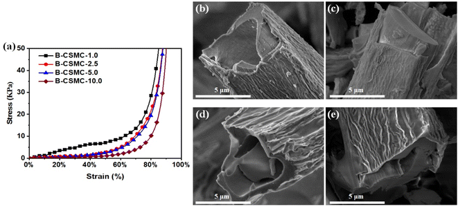
After the CSMC-X superfoams had been continuously burned by a butane flame for 5 minutes, the volume of the CSMC-X superfoam shrank to a certain extent, but it could still maintain a complete block structure (Fig. S11†). Interestingly, the CSMC-X superfoam burned by a butane flame (B-CSMC-X superfoam) still exhibits certain mechanical properties. As the concentration of SiO2 aerogel precursor concentration increases, the compressive strength of the B-CSMC-X superfoam gradually increases from a compressive strength of 2.0 kPa (B-CSMC-10.0 superfoam) to a compressive strength of 9.0 kPa (B-CSMC-1.0 superfoam) under a strain of 60% (Fig. 9a). Furthermore, the B-CSMC-5.0 superfoam could withstand about 268 times its own mass (Fig. S12†). The good mechanical properties of the B-CSMC-X superfoam indicate that the 3D network structure of the composite superfoam is not destroyed during butane flame combustion. Fig. 9b–e and S13† show the SEM images of the B-CSMC-X superfoam. The B-CSMC-X superfoam has a microtubular structure similar to that of the CSMC-X superfoam. The SiO2 aerogel shell on the surface of the composite microtubes was obviously wrinkled after CSMC-X superfoam had been burned by the butane flame. The carbon material (derived from cellulose microtubules, Fig. S14†) is separated from the SiO2 aerogel shell. The reason for the above phenomenon is that the volume of cellulose microtubes will be significantly reduced after combustion with a butane flame. However, the SiO2 aerogel shell will prevent the volume shrinkage of the composite microtubules. The B-CSMC-X superfoam can maintain a relatively complete 3D network structure, so the B-CSMC-X superfoam exhibits good mechanical properties. The B-CSMC-X superfoam also exhibits good thermal insulation properties. The thermal conductivity of the B-CSMC-X superfoam is about 0.050 W m−1 K−1 (Fig. S15†). The B-CSMC-X superfoam barely changed after burning with a butane flame for 3600 seconds (Fig. S16†). Only a small amount of white SiO2 material appeared on the burned surface of B-CSMC-X superfoam (Fig. S17†). This indicates that the SiO2 aerogel shell can effectively prevent oxygen penetration at high temperatures even in an aerobic environment, which endows B-CSMC-X superfoam excellent ablative resistance performance. Therefore, the B-CSMC-X superfoam not only has good mechanical properties, but also exhibits good ablative resistance performance.4. Conclusions
In conclusion, we are committed to using green and low-carbon processes for the preparation of thermal protection materials. A cellulose/SiO2 composite microtubule thermal insulation superfoam has been successfully prepared. Cellulose microtubules were successfully prepared from poplar sawdust using a chemical method. An SiO2 aerogel precursor solution can be quickly adsorbed by the delignified cellulose microtubes. The SiO2 aerogel shells are uniformly distributed only on the inner and outer walls of the delignified cellulose microtubes. The CSMC-X superfoam exhibits low density, good mechanical properties, and low thermal conductivity (as low as 0.042 ± 0.0018 W m−1 K−1). The CSMC-X superfoam exhibits excellent self-extinguishing and flame-retardant properties. The CSMC-X superfoam still exhibits certain mechanical properties after being burned by a butane flame. The thermal conductivity of the B-CSMC-X superfoam is about 0.050 W m−1 K−1. The B-CSMC-X superfoam barely changed after burning with a butane flame for 3600 seconds. Therefore, the hollow microtubule structure has excellent structural advantages in the field of lightweight high-performance thermal protection materials with heat insulation, flame retardance and even ablative resistance. Thermal protection materials based on a hollow microtubule structure have broad application prospects in construction, transportation, aerospace, and other fields.Author contributions
DH and XS: idea for the article, literature search and analysis, experiment, writing and revision of the manuscript. SZ: literature search and experiment. LW: idea for the article, analysis, revision of the manuscript. BA: analysis, revision of the manuscript. HS: experimental protocol design. YC: revision of the manuscript.Conflicts of interest
The authors declare no competing interests.References
- H. Vahabi, F. Laoutid, M. Mehrpouya, M. R. Saeb and P. Dubois, Mater. Sci. Eng., R, 2021, 144, 100604 CrossRef.
- Y. Niu, S. Wang, Z. Zhu, M. Su, Y. Wang, L. Yan, Y. Ma, H. Sun, W. Liang and A. Li, Polym. Degrad. Stab., 2022, 202, 110030 CrossRef CAS.
- J. R. Zhou, R. Zheng, J. Tang, H. J. Sun and J. Wang, J. Hazard. Mater., 2022, 438, 129449 CrossRef PubMed.
- L. E. Reynoso, A. B. Carrizo Romero, G. M. Viegas and G. A. San Juan, Constr. Build. Mater., 2021, 301, 124058 CrossRef CAS.
- H.-K. Peng, X. Wang, T.-T. Li, C.-W. Lou, Y. Wang and J.-H. Lin, Polym. Adv. Technol., 2019, 30, 2045–2055 CrossRef CAS.
- N. Singh, O. A. Ogunseitan, M. H. Wong and Y. Tang, Sustainable Horizons, 2022, 2, 100016 CrossRef.
- C. Chen and L. Hu, Matter, 2019, 1, 36–38 CrossRef.
- A. S. Wu, J. E. Oldfield and J. Adair, J. Anim. Sci., 1977, 44, 462–466 CrossRef CAS PubMed.
- J. C. Damfeu, P. Meukam and Y. Jannot, Thermochim. Acta, 2016, 630, 64–77 CrossRef CAS.
- J. Sun, Z. Wu, C. Ma, M. Xu, S. Luo, W. Li and S. Liu, J. Mater. Chem. A, 2021, 9, 13822–13850 RSC.
- E. Novitskaya, C. J. Ruestes, M. M. Porter, V. A. Lubarda, M. A. Meyers and J. McKittrick, J. Mech. Behav. Biomed. Mater., 2017, 76, 85–96 CrossRef CAS PubMed.
- G. Tlaiji, S. Ouldboukhitine, F. Pennec and P. Biwole, Constr. Build. Mater., 2022, 316, 125915 CrossRef CAS.
- H.-J. Zhan, K.-J. Wu, Y.-L. Hu, J.-W. Liu, H. Li, X. Guo, J. Xu, Y. Yang, Z.-L. Yu, H.-L. Gao, X.-S. Luo, J.-F. Chen, Y. Ni and S.-H. Yu, Chem, 2019, 5, 1871–1882 CAS.
- L. Zhuang, D. Lu, J. Zhang, P. Guo, L. Su, Y. Qin, P. Zhang, L. Xu, M. Niu, K. Peng and H. Wang, Nat. Commun., 2023, 14, 3178 CrossRef CAS PubMed.
- Z.-J. He, K. Chen, Z.-H. Liu, B.-Z. Li and Y.-J. Yuan, J. Cleaner Prod., 2023, 414, 137708 CrossRef CAS.
- Q. Tang, L. Fang, Y. Wang, M. Zou and W. Guo, Nanoscale, 2018, 10, 4344–4353 RSC.
- L. Liu, Z. Ji, S. Zhao, Q. Niu and S. Hu, J. Mater. Chem. A, 2021, 9, 6172–6179 RSC.
- X. Liu, M.-C. Li, Y. Lu, Z. Li, C. Liu, Z. Liu, C. Mei and Q. Wu, Prog. Nat. Sci.: Mater. Int., 2024, 162–171 CrossRef.
- H. Lichtenegger, M. Müller, O. Paris, C. Riekel and P. Fratzl, J. Appl. Crystallogr., 1999, 32, 1127–1133 CrossRef CAS.
- J. R. Barnett and V. A. Bonham, Biol. Rev., 2004, 79, 461–472 CrossRef CAS PubMed.
- J. Boyd, in New Perspectives in Wood Anatomy: Published on the Occasion of the 50th Anniversary of the International Association of Wood Anatomists, Springer, 1982, pp. 171–222 Search PubMed.
- Y. Hou, Q.-F. Guan, J. Xia, Z.-C. Ling, Z. He, Z.-M. Han, H.-B. Yang, P. Gu, Y. Zhu and S.-H. Yu, ACS Nano, 2020, 15, 1310–1320 CrossRef.
- R. Sinko and S. Keten, J. Mech. Phys. Solids, 2015, 78, 526–539 CrossRef CAS.
- C. Jia, C. Chen, R. Mi, T. Li, J. Dai, Z. Yang, Y. Pei, S. He, H. Bian and S.-H. Jang, ACS Nano, 2019, 13, 9993–10001 CrossRef CAS.
- M. I. Shams, H. Yano and K. Endou, J. Wood Sci., 2005, 51, 234–238 CrossRef CAS.
- W. Guo, X. Wang, P. Zhang, J. Liu, L. Song and Y. Hu, Carbohydr. Polym., 2018, 195, 71–78 CrossRef CAS.
- B. Wicklein, A. Kocjan, G. Salazar-Alvarez, F. Carosio, G. Camino, M. Antonietti and L. Bergstrom, Nat. Nanotechnol., 2015, 10, 277–283 CrossRef CAS PubMed.
- X. Shi, R. Bi, Z. Wan, F. Jiang and O. J. Rojas, ACS Nano, 2024, 18, 7959–7971 CrossRef CAS.
- I. Turku, A. Rohumaa, T. Tirri and L. Pulkkinen, Fire, 2024, 7, 31 CrossRef.
- S. Yan, D. Yi, H. Lu, L. Huang, X. Xu, M. Gao and J. Hao, Polym. Adv. Technol., 2024, 35, e6283 CrossRef CAS.
- L. Xia, C. Tan, W. Ren, X. Liu, X. Zhang, J. Wu, X. Zhang, F. Guo, Y. Yu and R. Yang, Carbohydr. Polym., 2024, 324, 121495 CrossRef CAS PubMed.
- R. Cheng, Y. Wu, B. Wang, J. Zeng, J. Li, J. Xu, W. Gao and K. Chen, J. Mater. Chem. A, 2023, 11, 18323–18335 RSC.
- J. L. Suter, D. Groen and P. V. Coveney, Adv. Mater., 2015, 27, 966–984 CrossRef CAS.
- J. Sun, Z. Wu, B. An, C. Ma, L. Xu, Z. Zhang, S. Luo, W. Li and S. Liu, Composites, Part B, 2021, 220, 108997 CrossRef CAS.
- K. Gao, J. Song, Q. Niu, Q. Tang, X. Sun and L. Wang, J. Mater. Sci., 2023, 58, 13009–13018 CrossRef CAS.
- S. K. Masthan, K. R. Rao, P. S. Prasad and P. K. Rao, Adsorpt. Sci. Technol., 1992, 9, 212–230 CrossRef CAS.
- Q. Niu, Q. Tang, X. Sun, L. Wang and K. Gao, J. Mater. Sci., 2022, 57, 5154–5166 CrossRef CAS.
- C. Chen, Y. Wang, Q. Wu, Z. Wan, D. Li and Y. Jin, Chem. Eng. J., 2020, 400, 125876 CrossRef CAS.
- I. Siro and D. Plackett, Cellulose, 2010, 17, 459–494 CrossRef CAS.
- C. C. Negrila, C. Cotirlan, F. Ungureanu, C. Logofatu and R. V. G. M. F. Lazarescu, J. Optoelectron. Adv. Mater., 2008, 10, 1379–1383 CAS.
- J. Raabe, A. d. S. Fonseca, L. Bufalino, C. Ribeiro, M. A. Martins, J. M. Marconcini and G. H. Denzin Tonoli, Carbohydr. Polym., 2014, 114, 424–431 CrossRef CAS.
- M. Kruk and M. Jaroniec, Chem. Mater., 2001, 13, 3169–3183 CrossRef CAS.
- D. K. Shen and S. Gu, Bioresour. Technol., 2009, 100, 6496–6504 CrossRef CAS PubMed.
- T. Du Tuan, N. Son Truong, D. Nam Duc, T. Ngan Ngoc Thanh, T. Quoc Ba, H. Ha Ky Phuong, N. Van Thi Thuy and P. Anh Ngoc, Mater. Chem. Phys., 2020, 253, 123363 CrossRef.
- Y. Chen, S. Sepahvand, F. Gauvin, K. Schollbach, H. Brouwers and Q. Yu, Constr. Build. Mater., 2021, 293, 123289 CrossRef CAS.
- J. Sun, Z. Wu, B. An, C. Ma, L. Xu, Z. Zhang, S. Luo, W. Li and S. Liu, Composites, Part B, 2021, 220, 108997 CrossRef CAS.
- X. Li, T. Zhong, Y. Xiao, H. Cheng and H. Chen, Carbohydr. Polym., 2024, 121966 CrossRef CAS.
- Y. Zhu, J. Zhu, Y. Li, J. Chen, O. Rojas and F. Jiang, ACS Sustain. Chem. Eng., 2023, 11, 16499–16508 CrossRef CAS.
- L. Chen, S. Wang, S. Wang, C. Chen, L. Qi, L. Yu, Z. Lu, J. Huang, J. Chen and Z. Wang, ACS Nano, 2022, 16, 16414–16425 CrossRef CAS.
- I. Hafez and M. Tajvidi, ACS Sustain. Chem. Eng., 2021, 9, 10113–10122 CrossRef CAS.
- L. Sun, L. Liu, M. Wu, D. Wang, R. Shen, H. Zhao, J. Lu and J. Yao, Carbohydr. Polym., 2023, 299, 120192 CrossRef CAS.
- C. Chen, Y. Zhou, W. Xie, T. Meng, X. Zhao, Z. Pang, Q. Chen, D. Liu, R. Wang and V. Yang, Adv. Funct. Mater., 2023, 33, 2204219 CrossRef CAS.
- Y. Hou, J. Liao, L. Huang, S. Guo, Y. Zhang, Z. Liu, L. Mo, X. Zhang and J. Li, J. Mater. Chem. A, 2023, 11, 1138–1147 RSC.
- H. Shao, Q. Zhang, H. Liu, W. Guo, Y. Jiang, L. Chen, L. He, J. Qi, H. Xiao and Y. Chen, Mater. Res. Express, 2020, 7, 055302 CrossRef CAS.
Footnote |
| † Electronic supplementary information (ESI) available. See DOI: https://doi.org/10.1039/d4ra00426d |
| This journal is © The Royal Society of Chemistry 2024 |

