 Open Access Article
Flexible tactile sensors with interlocking serrated structures based on stretchable multiwalled carbon nanotube/silver nanowire/silicone rubber composites†
Junyan Feng *a,
Hezheng Ao*b,
Peng Caob,
Tao Yangb and
Bo Xingc
aCollege of Mechanical and Electronic Engineering, Jiaxing Nanhu University, Jiaxing 314001, China. E-mail: 202408@jxnhu.edu.cn
bCollege of Mechanical Engineering, Zhejiang University of Technology, Hangzhou 310014, Zhejiang, China. E-mail: 2112102451@zjut.edu.cn
cCollege of Information Science and Engineering, Jiaxing University, Jiaxing 314000, China
First published on 29th April 2024
Abstract
Flexible tactile sensors have attracted significant interest because of their application scope in the fields of biomedicine, motion detection, and human–computer interaction. However, the development of tactile sensors with high sensitivity and flexibility remains a critical challenge. This study develops a patterned, stretchable, and fully elastomeric multiwalled carbon nanotube (MWCNT)/silver nanowire (Ag NW)/silicone rubber (SR) composite. The addition of Ag NWs to MWCNTs enhances the transmission path of the conductive network, yielding a CNT/Ag NW/SR composite with a sensitivity coefficient of 40. This characteristic renders it suitable for use as a piezoresistive sensing material. The interlocking sawtooth structure can convert the mechanical stimuli of the sensor to the tensile strain of the composite, thereby enhancing its sensitivity and flexibility. Experimental results indicate that the developed tactile sensor exhibited a sensitivity of 2.82 N−1 at 0–0.5 N and 1.51 N−1 at 0.5–2 N. These haptic sensors also demonstrate good dynamic response, repeatability, and long life. Furthermore, experimental results show that these haptic sensors exhibit high reproducibility, fast dynamic response, and good mechanical and electrical stability. Because of these exceptional properties, the as-prepared sensor can be applied in the development of smart robots, prosthetics, and wearable devices.
1 Introduction
With recent advancements in flexible and wearable electronic materials, the next generation of skin-mountable and implantable smart devices has extensive potential application scope in lifestyle modification, including personalized health monitoring,1–4 human–machine interfaces,5,6 soft robots,7–9 and implantable biomedical devices.10 In recent decades, wearable sensors have showcased attractive features such as miniaturization, multifunctionality, and smart integration, as well as wearable properties such as lightweightness, flexibility, stretchability, and conformability. In order to adapt the irregular surfaces of humans and robots, there has been significant effort to improve the flexibility and stretchability of the wearable electronic devices. Therefore, polymers based on elastic silicone rubber (SR) such as polydimethylsiloxane (PDMS),11 hydrogels,12 and copolyester (Ecoflex)13,14 have been employed as flexible substrates to enhance sensor flexibility. However, the tradeoff between high flexibility and sensitivity remains a key challenge in the development of tactile sensors.Various sensing systems, such as capacitive,15 piezoresistive,16–19 piezoelectric,20 and triboelectric,21 have been used in flexible tactile sensors. Piezoresistive sensors, which converts strain and stress to resistance, have attracted considerable attention owing to their simple structure, high sensitivity, wide dynamic measurement range, and convenient signal acquisition.22,23 Nowadays, the one-dimensional nanomaterials, such as carbon nanotubes (CNTs),24,25 silver nanowires (Ag NWs),26,27 and two-dimensional nanomaterial, such as graphene28 and MXene,29 have been used as the sensitive material to fabricate tactile sensor. MXene and graphene have excellent theoretical electrical conductivity and mechanical properties, thus the strain sensors exhibit high sensitivity. However, these materials always result in a small strain range and limited flexibility, making them unsuitable for monitoring full-range human body movements.30 One-dimensional carbon nanotubes have significant advantages in enhancing the stability and flexibility of tactile sensors due to their tubular structure, which provides high electrical conductivity, chemical stability, and flexibility. Unfortunately, current research indicates that strain sensors based on pure carbon nanotubes suffer from low sensitivity, nonlinearity, and poor recoverability.31,32 Therefore, it is of great significance to develop sensitive materials with excellent sensitivity and flexibility for the further development of tactile sensors.
Structural design of the sensor is also essential to develop tactile sensors with high sensitivity and flexibility. Various researchers have applied two-dimensional (2D) structures, including helix33 and serpentine modes,34,35 and three-dimensional (3D) structures, such as micro-pyramids,36 micro-pillars37 and micro-domes38,39 to maintain high electrical conductivity of electrodes under tensile conditions. However, most of the reported microstructures of flexible pressure sensors have been fabricated through photolithography, which involves the use of expensive equipment, complicated procedures, and time-consuming processes that are difficult to perform over large areas. Therefore, to develop a facile approach to improve the structure feature of sensor is also an important issue for the development of tactile sensor.
In this work, we proposed a novel, highly flexible and sensitive tactile sensor based on the stretchable sensitive material composed of multiwalled CNTs, Ag NWs, and SR, and an interlocked sawtooth structure was used to convert the external pressure applied on the sensor to the strain of the sensing composite. Mixing two or more conductive materials is beneficial to compensate the shortcomings of each component while maintaining the advantages of both, thereby improving the performance of the composite material.40–45 Jheng et al.43 reported that when CNTs fill the space of the Ag NWs network, a multiscale electron transport path is formed thus the CNT/AgNWs hybrid conductors have better mechanical compliance and conductivity than CNT conductors. However, research on the application of such materials in tactile sensors is still limited. In this work, the content of the nanofiller in this composite was adjusted to achieve a desired properties including excellent stretchability (80%), high conductivity (100 S m−1), and an exceptionally high gauge factor (40). Then this composite was encapsulated in a ductile self-locking structure to construct a tactile sensor. When the sensor is subjected to an external force, the top part of the self-locking structure compresses the sensitive material, creating stress concentration and leading to an amplified change in the local structure of the material, thus enhancing its resistance variation. The proposed flexible tactile sensor exhibited excellent performance in terms of detection range (0–2 N), response time (200 ms), recovery time (500 ms), and repeatability (200 cycles). The sensitivity was 2.82 N−1 at 0–0.5 N and 1.51 N−1 at 0.5–2 N. These results indicate that the sensor exhibited high electromechanical stability, repeatability, and fast dynamic response. Furthermore, human-wearing experiments were conducted to verify the applicability of the proposed tactile sensor in the accurate monitoring of human motion.
2 Experimental
2.1 Materials
All chemical reagents were of analytical grade and used without further purification. These include silver nitrate (AgNO3, ≥99.8%, Sinopharm), EG (EG, ≥99.0%, Sinopharm), acetone (C3H6O, ≥99.5%, Sinopharm), PVP (MW ≈ 1![[thin space (1/6-em)]](https://www.rsc.org/images/entities/char_2009.gif) 300
300![[thin space (1/6-em)]](https://www.rsc.org/images/entities/char_2009.gif) 000, Aldrich), ferric chloride hexahydrate (FeCl3·6H2O, ≥99.5%, Sinopharm), copper chloride dihydrate (CuCl2·2H2O, ≥99.5%, Sinopharm), sodium bromide (NaBr, ≥99.5%, Sinopharm), and ethanol (C2H5OH, ≥99.0%, Xilong Chemicals). MWCNTs with lengths of 10–20 μm, outer diameters of 4–6 nm, specific surface areas of 500–700 m2 g−1, and purities of >98% (China Organic Chemical Co., Ltd, Chinese Academy of Sciences, Chengdu, China) were used. SR (GD401, elongation 100%, tensile strength 1.0 MPa) was obtained from Zhonghao Chenguang Research Institute of Chemical Industry. It is one-component room-temperature vulcanized (RTV) SR with a base elastomer and a curing agent inside, and it can be cured when heated and exposed to air. Tetrahydrofuran (THF, Sinopharm Chemical Reagent Co., Ltd) was selected as the solvent because of its high polarity, making it suitable for nanomaterial dispersion.
000, Aldrich), ferric chloride hexahydrate (FeCl3·6H2O, ≥99.5%, Sinopharm), copper chloride dihydrate (CuCl2·2H2O, ≥99.5%, Sinopharm), sodium bromide (NaBr, ≥99.5%, Sinopharm), and ethanol (C2H5OH, ≥99.0%, Xilong Chemicals). MWCNTs with lengths of 10–20 μm, outer diameters of 4–6 nm, specific surface areas of 500–700 m2 g−1, and purities of >98% (China Organic Chemical Co., Ltd, Chinese Academy of Sciences, Chengdu, China) were used. SR (GD401, elongation 100%, tensile strength 1.0 MPa) was obtained from Zhonghao Chenguang Research Institute of Chemical Industry. It is one-component room-temperature vulcanized (RTV) SR with a base elastomer and a curing agent inside, and it can be cured when heated and exposed to air. Tetrahydrofuran (THF, Sinopharm Chemical Reagent Co., Ltd) was selected as the solvent because of its high polarity, making it suitable for nanomaterial dispersion.
2.2 Synthesis of Ag NWs
Ultra-long Ag NWs were synthesized via a one-step chemical reaction. First, 1.2 g of PVP (MW ≈ 1![[thin space (1/6-em)]](https://www.rsc.org/images/entities/char_2009.gif) 300
300![[thin space (1/6-em)]](https://www.rsc.org/images/entities/char_2009.gif) 000) was dissolved in 50 mL of EG. The solution was then heated and continuously stirred at 170 °C for 1 h. Subsequently, 1 mL of CuCl2·2H2O (9.8 mM) and 1 mL FeCl3·6H2O (3.9 mM) and 10 mL of NaBr solution (1.05 mM) was added to the mixture and stirred for 15 min at 170 °C. Finally, 10 mL of AgNO3 (0.6 M) was added to the mixed solution, which was stirred at 170 °C for 45 min and cooled down to room temperature.
000) was dissolved in 50 mL of EG. The solution was then heated and continuously stirred at 170 °C for 1 h. Subsequently, 1 mL of CuCl2·2H2O (9.8 mM) and 1 mL FeCl3·6H2O (3.9 mM) and 10 mL of NaBr solution (1.05 mM) was added to the mixture and stirred for 15 min at 170 °C. Finally, 10 mL of AgNO3 (0.6 M) was added to the mixed solution, which was stirred at 170 °C for 45 min and cooled down to room temperature.
2.3 Preparation of CNT/Ag NW/SR composites
First, using an ultrasonic processor (FS-300N, Shanghai Songxi Ultrasonic Instrumentation Co.), different mass fractions of CNTs were dispersed in THF for 1 h at a power of 100 W; subsequently, different mass fractions of Ag NWs were added to the dispersion and magnetically stirred for 15 min to and ultrasound for 10 min homogeneously disperse the Ag NWs in the solution. SR was also added to the dispersion and magnetically stirred for 15 min. Finally, the homogeneous suspension was warmed up to 80 °C under magnetic stirring to remove excess solvent, and a high-viscosity CNT/Ag NW/SR composite mixture was obtained. A high-viscosity mixture was formed upon continuous stirring, ensuring that the composites did not undergo severe agglomeration in SR.3 Results and discussion
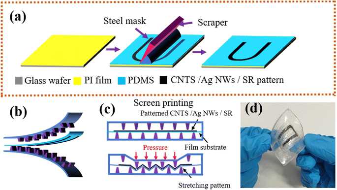
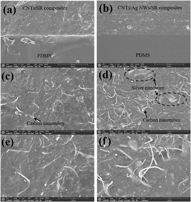
The proposed flexible tactile sensor was fabricated using a multistep process, as shown in Fig. 1a. Step 1: a glass wafer covered with a thin PI film was prepared, and a 100 mm layer of polydimethylsiloxane (PDMS) was rotationally coated on the PI film and cured. Step 2: the steel mold with patterned hollow grooves was securely placed over the substrate. A paste mixture of CNT/Ag NW/SR composites was applied to the mask using a squeegee, and the residual mixture was wiped away. After the mask was removed, the CNT/Ag NW/SR composite maintained its designated pattern on the PDMS substrate. Step 3: a serrated layer with upper and lower interlocking was fabricated using the mold-casting method (Fig. 1b). Plastic molds with the designed recesses were prepared and cleaned with ethanol in an ultrasonic bath. PDMS was poured over the mold, degassed, and heated to cure. The cured serrated layer was then peeled off. Step 4: the prepared composite patterned layer was aligned with the serrated layer, and a thin layer of PDMS was applied to the edges and heat-cured to allow them to assemble together (Fig. 1d). Fig. 1c shows the cross-section of the sensor, a composite pattern with a thin-film backing was sandwiched between the top and bottom sawtooth structures. When the external pressure was applied on the cell, the top serration compresses the composite pattern into the gap between the serrations. This created an interlocking structure that stretches the composite pattern and produces a significant change in resistance. When the compression pressure was removed, the film substrate supports the composite pattern, returning to its original state.We first investigated the morphologies of the CNT/SR and CNT/Ag NW/SR composites through SEM (Helios 5 CX, USA). Fig. 2a, c and e show the cross-sectional SEM images of the CNT/SR composites. Fig. 2b, d and f show the cross-sectional images of the CNT/Ag NW/SR composites. Fig. 2a and b show that the smooth PDMS substrate and nanocomposites could be easily divided into two layers, with almost no delamination boundary between the two layers. This shows that the composite material was closely combined with the PDMS substrate, thereby improving the strength and reliability of the composite material. Fig. 2c and e show the cross-sectional SEM images of the CNT/SR composites at ×10![[thin space (1/6-em)]](https://www.rsc.org/images/entities/char_2009.gif) 000 and ×20
000 and ×20![[thin space (1/6-em)]](https://www.rsc.org/images/entities/char_2009.gif) 000 magnifications, respectively. The CNTs were uniformly dispersed and enveloped by SR, with no significant number of neat planar substrates observed, indicating a more continuous and uniform conductive network. Fig. 2d and f show the morphology of the CNT/Ag NW/SR composites. The nanofillers were uniformly dispersed in the SR matrix. The addition of Ag NWs also produces denser conductive paths. Because Ag NWs have been proven to have excellent intrinsic conductivity, the conductivity of the CNT/SR composites will be significantly improved. The SEM images of CNT/Ag NW/SR composite surface under different tensile strains are shown in Fig. S1.† The microstructures indicate that the silver nanowires and carbon nanotubes within the composite present uniform deformability along with the elastic deformation of SR.
000 magnifications, respectively. The CNTs were uniformly dispersed and enveloped by SR, with no significant number of neat planar substrates observed, indicating a more continuous and uniform conductive network. Fig. 2d and f show the morphology of the CNT/Ag NW/SR composites. The nanofillers were uniformly dispersed in the SR matrix. The addition of Ag NWs also produces denser conductive paths. Because Ag NWs have been proven to have excellent intrinsic conductivity, the conductivity of the CNT/SR composites will be significantly improved. The SEM images of CNT/Ag NW/SR composite surface under different tensile strains are shown in Fig. S1.† The microstructures indicate that the silver nanowires and carbon nanotubes within the composite present uniform deformability along with the elastic deformation of SR.
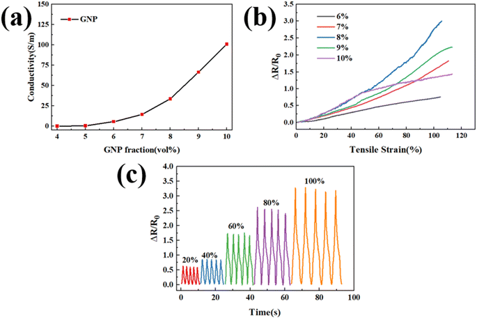
The effects of nanofillers on electromechanical properties of the composites were then investigated. Fig. 3a shows the electrical conductivity of the CNT/SR composites with CNT mass fractions of 4, 5, 6, 7, 8, and 10 wt%. The electrical conductivity of the CNT/SR composites monotonically increased with an increase in the CNT mass fraction. This indicates that a higher CNT content leads to the formation of a denser and more uniformly conductive network. In addition, a sharp increase in conductivity was observed between 7 and 10 wt%, suggesting that the most sensitive specimens had a CNT content between 7 and 10 wt%.
Fig. 3b shows the relative resistance change (ΔR/R0) of the CNT/SR composites under different tensile strains. The maximum value of 3 was obtained when the CNT/SR composite contains 8% CNT was stretched by 100%. The strain sensitivity of the composite was reduced to 1.5 when the mass fraction of CNT was increased to 10%. A higher CNT content led to a denser conductive network inside the composite. Consequently, the number of conductive paths changed more slowly when tensile strain was applied. Multicycle tests were conducted on the CNT composites with varying CNT mass fractions and strains. The results show that the variation in the magnitude of ΔR/R0 is closely related to the cyclic tensile strain. As shown in Fig. 3c, at a strain of 20%, the relative resistance change was approximately 0.6; at a strain of 60%, it was approximately 1.7; and at a strain of 100%, it was approximately 3.2.
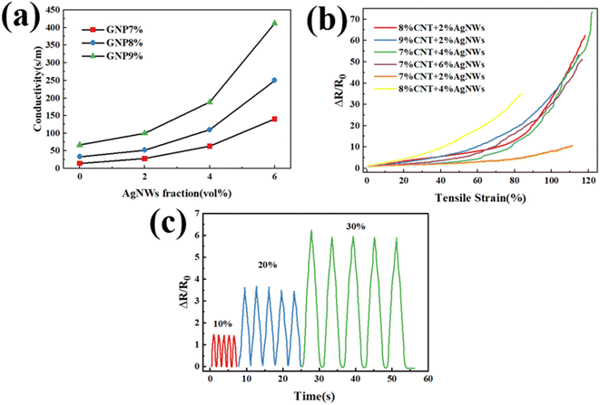
The incorporation of Ag NWs into the CNT/SR composites enabled the formation of a composite with two conductive compositions. This approach was employed to overcome the drawbacks of each component, while maintaining their corresponding advantages. Because the inherent tensile properties of SR materials can reach up to 100%, increasing the amount of Ag NWs does not affect the tensile properties of the composites. However, owing to the excellent intrinsic conductivity of Ag NWs, their incorporation results in denser electrical paths, thereby achieving enhanced conductivity within the mixed system. To further explore the influence of Ag NWs on the composites, we examined the electromechanical properties of CNT/Ag NW/SR composites which contain different mass fraction of CNTs and Ag NWs. The mass fractions of CNTs were selected as 7, 8, and 9 wt%, and Ag NWs with different mass fraction were added to the composites. Fig. 4a shows that the conductivity increased monotonically as the mass fraction of the Ag NWs increased from 0 to 6 wt%. This indicates that the higher the Ag NWs mass fraction, the denser and more uniform the conductive network.
Fig. 4b shows the change of relative resistance of the CNT/Ag NW/SR composites under different composition and tensile strains. It can be found that the ΔR/R0 curve becomes smooth and monotonous as the CNT/Ag NW/SR composites are stretched. However, when 4 or 6 wt% Ag NWs are added, ΔR/R0 becomes unstable and fluctuates. This indicates that the Ag NWs were not uniformly and stably dispersed in the SR matrix. Therefore, we can infer that the addition of excess Ag NWs hindered the dispersion uniformity and stability of the nanocomposites. Table S1† lists the detailed value of ΔR/R0 of the composite with different mass fraction of CNTs and Ag NWs. When SR composited with 8 wt% CNTs and 4 wt% Ag NWs, the composites had a conductivity of 100 S m−1, an elongation of 80%, and a sensitivity coefficient of nearly 40. This value of sensitivity coefficient is far exceeding the composite prepared using carbon nanotubes and silicone rubber as reported in the literature.14,46 Thus the result indicates that this CNT/Ag NW/SR composite can be used as sensitive element with high sensitivity and good tensile properties. Fig. 4c shows the composites tested for multiple cycles under different strains. The change in the magnitude of ΔR/R0 is closely related to the cyclic tensile strain. At a strain of 10%, ΔR/R0 was approximately 1.5; at a strain of 20%, it was approximately 3.5; and at a strain of 30%, it was approximately 6.
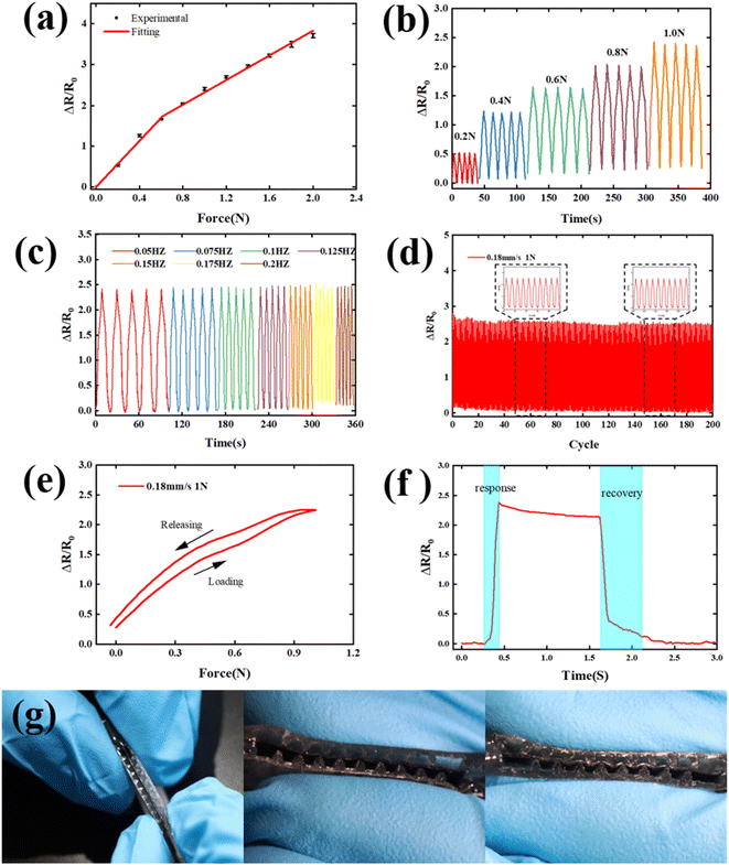
Fig. 5 shows the force-sensing performance of the developed flexible tactile sensor. As the applied force increased from 0 to 2 N, the measured resistance increased almost linearly (Fig. 5a), exhibited high linear sensitivity in this range. For the smaller force range (0–0.5 N), the sensor exhibited a sensitivity of 2.82 N−1 (0–6.4 kPa), while for the larger force range (0.5–2 N), the sensitivity was 1.51 N−1 (6.4–25.6 kPa). This result is superior to the recently reported value that a composite contains carbon nanotubes, graphene, and silicone rubber was used as the sensitive material,47 indicates that our sensor has well capable of perceiving minute strains. To investigate the power-sensing performance, cyclic loading and unloading tests were conducted at different loading forces and frequencies; the results are shown in Fig. 5(b) and (c). As shown in Fig. 5(b), a change in the relative resistance of the sensor was observed over a wide range of forces. Five repetitive loading/unloading cycles with different applied forces were performed at constant loading rates. The relative resistance was 1.25 at a 0.4 N loading force, 1.6 at a 0.6 N loading force, 2 at a 0.8 N loading force, and 2.5 at a 1 N loading force. This indicates that the sensing unit generally exhibits a good resistive response to different applied forces. As shown in Fig. 5(c), the test tactile sensor exhibited a detection force of 1 N. The loading frequency ranged from 0.08 to 0.2 Hz, and each set was repeated for five cycles. As the loading frequency increased, the cyclic changes in voltage became more frequent. The peak values of all the cycles were similar, indicating a good dynamic response and stability.
To further demonstrate its durability and repeatability, 200 loading/unloading cycles were performed at a constant loading rate of 0.18 mm s−1 at a normal force of 1 N, the result was shown in Fig. 5(d). The black dashed boxes on the left and right show several cyclic loading–unloading profiles throughout the cyclic test. A slight decrease occurred initially, and the relative resistance of the sensing unit stabilized as the number of cycles increased. These results indicate that our tactile sensor can serve as a reliable long-term force-sensing sensor. As shown in Fig. 5(e), during the loading and unloading of 1 N at a loading speed of 0.18 mm s−1, the sensor exhibited high elastic performance with a resistance hysteresis of 10.1%. For further applications, the response time of the sensor was considered. A stepping force input of 1 N was applied to the sensing unit, and the loading time was maintained at 1.5 s. Fig. 5f shows that the sensing unit had a relatively fast response time of 180 ms and a recovery time of 500 ms. When the loading force was completely released, the relative resistance of the output changed by 10.4%. The output of the sensing unit did not return to its original value within a short time, and the unloading time was slightly longer than that of the loading process. This can potentially be attributed to the hysteresis of the nanocomposites. When the composite pattern is stretched and released, the composite material in SR may change slightly, resulting in a new conductive network; thus, the sensing unit does not return to its original state. Fig. 5g shows the cross-section of the final fabricated tactile sensor. When the force is applied initially, the composite pattern can be easily extruded and the deformation occurs immediately. With the increase of the applied force, the contact surface between composite and the serrations increase, thus the deformation of the pattern becomes smaller. Finally, the composite layer reaches the bottom of the gap and no further deformation occurs.
Fig. S2† shows the changes in the performance of the tactile sensor after being placed at room temperature for a long time. It can be found that the sensitivity and cycle stability of the sensor have not significantly degraded after being placed at room temperature for three months, indicates that the sensor has good long-term stability. In this study, the CNTs and Ag NWs are completely embedded within the silicone rubber, which prevents oxidation of the silver nanowires and carbon nanotubes. Additionally, silicone rubber also possesses excellent room-temperature stability, thus the sensor's sensitivity performance is well safeguarded. Fig. S3† shows the fatigue characteristics of the sensitive composite within sensor under different service environments. When the sensor was cycled 200 times per day at its maximum compressive volume (actual deformation of the sensitive material is up to 20%), after 30 days of continuous operation, no cracks are observed on surface of the sensitive material, as shown in Fig. S3a,† indicating that the sensor has good fatigue resistance under this strain conditions. However, when the sensor is continuously cycled at a tensile deformation of 80% for 200 cycles, cracks appear on surface of the sensitive material, as shown in fig. S3b,† indicating that excessive tensile strain can damage the fatigue performance of the sensor. In practical applications, there are many factors affecting the fatigue performance of sensors, including the composition of sensitive material, structure of the sensor, direction and magnitude of cyclic strain, and environmental temperature, etc. In the next step, it is necessary to systematically design experiments to study the fatigue performance of the sensor thus to further enhance the stability and fatigue performance of the sensor.
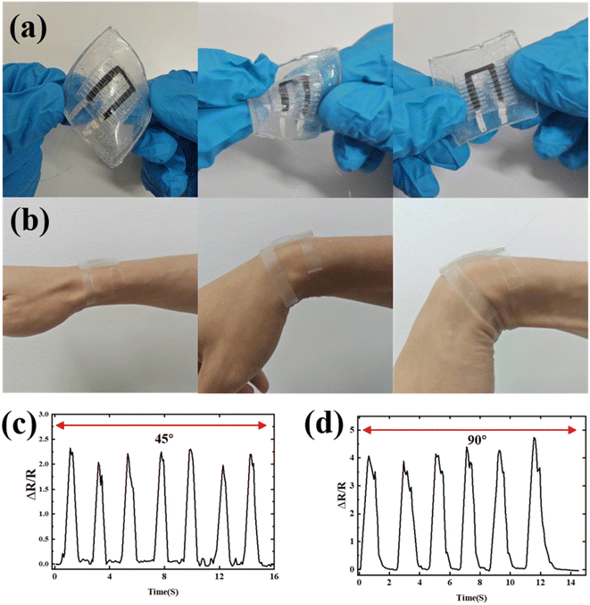
To verify the flexibility and stretchability of the fabricated tactile sensors, the haptic sensor was subjected to bending, stretching, and twisting; the images are shown in Fig. 6a. Almost no delamination or disconnection of the sensor was observed during these deformation processes. The tactile sensor with the multilayer structure, including the composite pattern, and top and bottom serrated layers, exhibited high flexibility and stability owing to the presence of the PDMS substrate. To further demonstrate the applicability of haptic sensors, we conducted wearable experiments for human motion monitoring. The haptic sensor was mounted on the wrist using an adhesive tape. Subsequently, the wrist was repeatedly bent to 45° and 90° and then returned to a stretched state, as shown in Fig. 6b. Finally, the resistance signals during movement were recorded by the measurement circuit; the results are plotted in Fig. 6c and d. The changes in the signals of the haptic sensors were nearly synchronized with the movement of the wrist. When the wrist was flexed at 45°, the sensor produced a response of 2.3 (Fig. 6c). This indicates that the cells in the sensor were partially deformed owing to wrist flexion. In this case, the deformation of the units was not completely uniform. When the wrist was bent to 90°, the response of the units in the sensor increased to 4.5 (Fig. 6d). These results confirmed that the CNT/Ag NW/SR composite haptic sensors exhibit good repeatability and stability in human motion monitoring and have great potential for applications in health monitoring and development of wearable devices and smart products.
4 Conclusions
In this study, we developed a flexible tactile sensor that uses an interlocking serrated structure to enhance force-sensing sensitivity and detection range. Because of its structure, the sensor could effectively convert external forces and pressures to tensile strains within the sensing material. Tactile sensors were successfully prepared using the proposed cost-effective fabrication method and procedures. CNT/Ag NW/SR composites were prepared with an extremely high specification factor of 40 and a conductivity of 100 S m−1. The overall structure of the sensor is flexible and can withstand significant bending on curved surfaces. The characterization results confirmed that the developed tactile sensor exhibited high linear sensitivity in the sensing range of 0–2 N. Specifically, it showcased a sensitivity of 2.82 N−1 for the small force range (0–0.5 N) and 1.51 N−1 for the large force range (0.5–2 N). Cyclic loading and unloading test results revealed that the tactile sensor exhibited good resistive responsiveness, recovery, and repeatability. The results of preliminary human posture monitoring experiments indicated that the developed haptic sensor could accurately measure the signals. Therefore, this highly sensitive and flexible tactile sensor can be readily applied in the development of wearable electronics for smart robotics and smart prosthetics and in healthcare monitoring.Data Availability
Data and materials will be made available on request.Author contributions
H. Z. A.: investigation, data curation, writing – original draft preparation, writing – review and editing, formal analysis. J. Y. F.: conceptualization, investigation, methodology, validation, data curation, writing – review and editing, resources, supervision, project administration. P. C.: investigation, data curation, formal analysis. T. Y.: investigation, data curation, formal analysis. T. S.: formal analysis. B. X.: review and editing, formal analysis, funding acquisition.Conflicts of interest
No potential conflict of interest was reported by the authors.Acknowledgements
This work is supported by the Science and Technology Project of Jiaxing (2022AY10005); Science and Technology Project of Jiaxing (2019AY11018); General scientific research project of Zhejiang Education Department (Y202250333).References
- Y. He, M. Zhou, M. H. H. Mahmoud, X. Lu, G. He, L. Zhang, M. Huang, A. Y. Elnaggar, Q. Lei, H. Liu, C. Liu and I. H. El Azab, Adv. Compos. Hybrid Mater., 2022, 5, 1939–1950 CrossRef CAS.
- D. Wang, B. Sheng, L. Peng, Y. Huang and Z. Ni, Polymers, 2019, 11, 1433 CrossRef CAS PubMed.
- Y. Xiong, J. Xiao, J. Chen, D. Xu, S. Zhao, S. Chen and B. Sheng, Soft Matter, 2021, 17, 10016–10024 RSC.
- M. Zhu, Z. Sun, T. Chen and C. Lee, Nat. Commun., 2021, 12, 2692 CrossRef CAS PubMed.
- T. Qin, X. Li, A. Yang, M. Wu, L. Yu, H. Zeng and L. Han, Chem. Eng. J., 2023, 461, 141905 CrossRef CAS.
- Y. Wang, Y. Yue, F. Cheng, Y. Cheng, B. Ge, N. Liu and Y. Gao, ACS Nano, 2022, 16, 1734–1758 CrossRef CAS PubMed.
- Y. Ma, N. Liu, L. Li, X. Hu, Z. Zou, J. Wang, S. Luo and Y. Gao, Nat. Commun., 2017, 8, 1207 CrossRef PubMed.
- J. Xie, Y. Zhao, D. Zhu, J. Li, M. Qiao, G. He, S. Deng and J. Yan, ACS Appl. Mater. Interfaces, 2023, 15, 12551–12559 CrossRef CAS PubMed.
- T. Jia, Y. Wang, Y. Dou, Y. Li, M. J. de Andrade, R. Wang, S. Fang, J. Li, Z. Yu, R. Qiao, Z. Liu, Y. Cheng, Y. Su, M. Minary-Jolandan, R. H. Baughman, D. Qian and Z. Liu, Adv. Funct. Mater., 2019, 29, 1808241 CrossRef.
- E. A. Al-Suhaimi, M. A. Aljafary, T. M. Alfareed, H. A. Alshuyeh, G. M. Alhamid, B. Sonbol, A. Almofleh, F. M. Alkulaifi, R. K. Altwayan, J. N. Alharbi, N. M. Binmahfooz, E. S. Alhasani, H. Tombuloglu, A. S. Rasdan, A. A. Lardhi, A. Baykal and A. M. Homeida, Front. Energy Res., 2022, 10, 900534 CrossRef.
- Y. Pang, Y.-X. Li, Q. Wang, T.-Y. Zhang, J.-B. Wang, X. Liu, Y.-Y. Yang, J.-M. Jian, M.-Q. Jian, Y.-Y. Zhang, Y. Yang and T.-L. Ren, ACS Appl. Mater. Interfaces, 2018, 10, 3948–3954 CrossRef PubMed.
- H. Liu, Y. Wang, Z. Shi, D. Tan, X. Yang, L. Xiong, G. Li, Y. Lei and L. Xue, Small Methods, 2022, 6, 2200461 CrossRef CAS PubMed.
- Q. Liu, S. Zhao, T. Hu, C. Jiang and B. Sheng, IEEE Sensor. J., 2023, 23, 8268–8276 CAS.
- V. Kumar, G. Lee, Monika, J. Choi and D.-J. Lee, Polymer, 2020, 190, 122221 CrossRef.
- Z. Duan, Y. Jiang, Q. Huang, Z. Yuan, Q. Zhao, S. Wang, Y. Zhang and H. Tai, J. Mater. Chem. C, 2021, 9, 13659–13667 RSC.
- H. Li, J. Chen, X. Chang, Y. Xu, G. Zhao, Y. Zhu and Y. Li, J. Mater. Chem. A, 2021, 9, 1795–1802 RSC.
- F. Wang, J. Chen, X. Cui, X. Liu, X. Chang and Y. Zhu, ACS Appl. Mater. Interfaces, 2022, 14, 30268–30278 CrossRef CAS PubMed.
- Z. Yu, J. Xu, H. Gong, Y. Li, L. Li, Q. Wei and D. Tang, ACS Appl. Mater. Interfaces, 2022, 14, 5101–5111 CrossRef CAS PubMed.
- F. Guan, Z. Han, M. Jin, Z. Wu, Y. Chen, S. Chen and H. Wang, Adv. Fiber Mater., 2021, 3, 128–137 CrossRef CAS.
- J. B. Park, M. S. Song, R. Ghosh, R. K. Saroj, Y. Hwang, Y. Tchoe, H. Oh, H. Baek, Y. Lim, B. Kim, S.-W. Kim and G.-C. Yi, NPG Asia Mater., 2021, 13, 57 CrossRef CAS.
- G. Zhao, Y. Zhang, N. Shi, Z. Liu, X. Zhang, M. Wu, C. Pan, H. Liu, L. Li and Z. L. Wang, Nano Energy, 2019, 59, 302–310 CrossRef CAS.
- L. Zhu, Y. Wang, D. Mei, W. Ding, C. Jiang and Y. Lu, ACS Appl. Mater. Interfaces, 2020, 12, 31725–31737 CrossRef CAS PubMed.
- Y. Wang, L. Zhu, D. Mei and W. Zhu, J. Mater. Chem. C, 2019, 7, 8669–8679 RSC.
- T. Yan, Y. Wu, W. Yi and Z. Pan, Sens. Actuators, A, 2021, 327, 112755 CrossRef CAS.
- S. Shang, L. Gan, C. W. M. Yuen, S.-x. Jiang and N. M. Luo, Composites, Part A, 2014, 66, 135–141 CrossRef CAS.
- S. Peng, S. Wu, Y. Yu, Z. Sha, G. Li, H. Trung Thien, T. Mai Thanh, D. Thanh Nho, D. Chu and C. H. Wang, J. Mater. Chem. A, 2021, 9, 26788–26799 RSC.
- X. Liu, G. Chen, J. Bao and X. Xu, Adv. Fiber Mater., 2022, 4, 66–75 CrossRef CAS.
- H. Chen, F. Zhuo, J. Zhou, Y. Liu, J. Zhang, S. Dong, X. Liu, A. Elmarakbi, H. Duan and Y. Fu, Chem. Eng. J., 2023, 464, 142576 CrossRef CAS.
- J. Yan, Y. Ma, G. Jia, S. Zhao, Y. Yue, F. Cheng, C. Zhang, M. Cao, Y. Xiong, P. Shen and Y. Gao, Chem. Eng. J., 2022, 431, 133458 CrossRef CAS.
- Y. Yang, Z. Cao, P. He, L. Shi, G. Ding, R. Wang and J. Sun, Nano Energy, 2019, 66, 104134 CrossRef CAS.
- M. Ramuz, B. Tee, J. Tok and Z. Bao, Adv. Mater., 2012, 24, 3223–3227 CrossRef CAS PubMed.
- Y. Li, Y. Shang, X. He, Q. Peng, S. Du, E. Shi, S. Wu, Z. Li, P. Li and A. Cao, ACS Nano, 2013, 7, 8128–8135 CrossRef CAS PubMed.
- S. Zhang, B. Wang, J. Jiang, K. Wu, C. F. Guo and Z. Wu, ACS Appl. Mater. Interfaces, 2019, 11, 7148–7156 CrossRef CAS PubMed.
- Z. Yan, T. Pan, D. Wang, J. Li, L. Jin, L. Huang, J. Jiang, Z. Qi, H. Zhang, M. Gao, W. Yang and Y. Lin, ACS Appl. Mater. Interfaces, 2019, 11, 12261–12271 CrossRef CAS PubMed.
- C. Jiang, Q. Li, S. Fan, Q. Guo, S. Bi, X. Wang, X. Cao, Y. Liu and J. Song, Nano Energy, 2020, 73, 104782 CrossRef CAS.
- S. Lee, J. Oh, J. C. Yang, J. Y. Sim, J. Ryu, J.-O. Kim and S. Park, Adv. Mater. Technol., 2018, 3, 1800307 CrossRef.
- S. Chun, Y. Choi, D. I. Suh, G. Y. Bae, S. Hyun and W. Park, Nanoscale, 2017, 9, 10248–10255 RSC.
- Y. Jeong, J. Gu, J. Byun, J. Ahn, J. Byun, K. Kim, J. Park, J. Ko, J.-h. Jeong, M. Amjadi and I. Park, Adv. Healthcare Mater., 2021, 10, 2001461 CrossRef CAS PubMed.
- H. Chen, Y. Jing, J.-H. Lee, D. Liu, J. Kim, S. Chen, K. Huang, X. Shen, Q. Zheng, J. Yang, S. Jeon and J.-K. Kim, Mater. Horiz., 2020, 7, 2378–2389 RSC.
- Y. Wang, S. Dai, D. Mei and J. Jin, IEEE Trans. Instrum. Meas., 2022, 71, 9502710 CAS.
- S. Shajari, S. Ramakrishnan, K. Karan, L. J. Sudak and U. Sundararaj, Appl. Mater. Today, 2022, 26, 101295 CrossRef.
- W.-B. Zhu, S.-S. Xue, H. Zhang, Y.-Y. Wang, P. Huang, Z.-H. Tang, Y.-Q. Li and S.-Y. Fu, J. Mater. Chem. C, 2022, 10, 8226–8233 RSC.
- L.-C. Jheng, C.-H. Hsiao, W.-C. Ko, S. L.-C. Hsu and Y.-L. Huang, Nanotechnology, 2019, 30, 235201 CrossRef CAS PubMed.
- Y. Wang, W. Qin, M. Yang, Z. Tian, W. Guo, J. Sun, X. Zhou, B. Fei, B. An, R. Sun, S. Yin and Z. Liu, Adv. Funct. Mater., 2023, 33, 2301587 CrossRef CAS.
- Y. Wang, W. Qin, X. Hu, Z. Liu, Z. Ren, H. Cao, B. An, X. Zhou, M. Shafiq, S. Yin and Z. Liu, Sens. Actuators, B, 2022, 368, 132228 CrossRef CAS.
- M. Amjadi, Y. Yoon and I. Park, Nanotechnology, 2015, 26, 375501 CrossRef PubMed.
- S. Dai, Y. Wang, D. Mei, K. Tao and S. Wang, IEEE Trans. Electron Devices, 2023, 5, 2465–2472 Search PubMed.
Footnote |
| † Electronic supplementary information (ESI) available. See DOI: https://doi.org/10.1039/d4ra00381k |
| This journal is © The Royal Society of Chemistry 2024 |

