
 Open Access Article
 This Open Access Article is licensed under a Creative Commons Attribution-Non Commercial 3.0 Unported Licence
Graphene oxide functionalized with N-methyl-D-glucamine as a novel sorbent for boron removal from produced and formation waters
Izylla O. de Lucenaa,
Jefferson S. de Gois b and
Ricardo J. Cassella*a
b and
Ricardo J. Cassella*a
aDepartamento de Química Analítica, Universidade Federal Fluminense, Outeiro de São João Batista s/n, Centro, Niterói/RJ, 24020-141, Brazil. E-mail: rcassella@id.uff.br
bDepartamento de Química Analítica, Universidade do Estado do Rio de Janeiro, Rua São Francisco Xavier 524 – Maracanã, Rio de Janeiro/RJ, 20550-013, Brazil
First published on 9th February 2024
Abstract
This work describes the synthesis of a novel material based on graphene oxide (GO) for the selective removal of boron in an aqueous medium. The material was obtained by functionalizing graphene oxide with N-methyl-D-glucamine (NMDG). This material, named NMDG@GO, was successfully characterized using Fourier-transform infrared spectroscopy, scanning electron microscopy, X-ray diffraction, thermogravimetric analysis, atomic force microscopy, and elemental analysis. The adsorption process was studied from a kinetic perspective using pseudo-first-order and pseudo-second-order models, with the pseudo-second-order model presenting a better fit. The adsorption process was studied using Langmuir and Freundlich isotherms, with the Freundlich model providing a better fit and an r2 value of 0.9368. This result indicates that the adsorption process occurred in multilayers, considering a heterogeneous distribution of adsorption sites. The levels of the factor's adsorbent mass, pH, and time were optimized using a central composite design, with the optimal values achieved at 120 mg of material, pH = 2.0, and an agitation time of 40 min. Under these optimized conditions, it was possible to remove 22 to 35% of the boron present in saline waters from oil production (production and formation waters) using the developed adsorbent.
1. Introduction
Boron is a non-metallic element from group 13 of the periodic table, typically found in the environment as boric acid (H3BO3) and/or borate ions (B(OH)4−). It is essential for the maintenance of both animal and plant life when present in low concentrations.1 Boron concentrations in nature can vary depending on the environment, with levels of up to 100 mg kg−1 in soil and an average concentration of 4.5 mg L−1 in oceans.2,3Boron can be found in numerous industrial applications, including the production of glass, ceramics, cosmetics, pharmaceuticals, capacitors, semiconductors, soaps, detergents, and in agriculture in the formulations of some pesticides and fertilizers.4,5 These anthropogenic sources of boron can lead to an increase in its concentration in wastewater and industrial effluents, potentially contaminating surface waters used for human consumption. It is important to note that high concentrations of boron can adversely affect plant growth and have implications for animal and human life.4
The World Health Organization (WHO) has established the maximum tolerated limit for boron in drinking water at 2.4 mg L−1, while the European Union (EU) has set this concentration at 1.0 mg L−1.1,6,7 In Brazil, there is no specific regulation for boron concentration in drinking water, but the maximum allowable limit for industrial effluents is 5.0 mg L−1, except for the disposal of saline waters (salinity > 30‰). These values are determined by Brazilian authorities through CONAMA (National Council for the Environment).8–10
The oil extraction process, particularly in offshore environments, generates substantial volumes of water, primarily from the secondary oil recovery process. These waters are discharged into oceans and seas, potentially affecting the environment due to, among other factors, the high concentrations of boron compounds present in these effluents. Since there is no specific regulation for this type of effluent, boron contamination has not yet been recognized as a risk.3,10 In the current literature, various strategies for removing boron from saline waters are discussed, including reverse osmosis,11 chemical precipitation,5 electrocoagulation, membrane filtration,12 ion exchange,13 and adsorption.14,15 Among these methods, adsorption processes can be highlighted for their simplicity and relatively lower cost compared to other methods. Additionally, a wide range of adsorbent materials can be employed, such as activated carbon, layered double hydroxides, ashes, minerals, nanomaterials, and resins, among others.16
The modification of polymeric supports with N-methyl-D-glucamine (NMDG) is an effective approach for boron removal in water.14 Several commercial products with these characteristics are commercially available, such as XSC-70, VBC-NMDG, and Amberlite IRA 743 resins.17 This is because NMDG is an organic molecule containing multiple hydroxyl groups in its structure, which gives it a high affinity for boron through the formation of coordination complexes.18 Table 1 shows a comparison among different sorbent materials already employed for boron removal from aqueous medium.19–27
| Sorbent material | Sample | Removal | Ref. |
|---|---|---|---|
| a N-Methyl-D-glucamine (NMDG)@γ-glycidoxypropyl-trimethoxysilane (GPTMS).b HPEI = hydroxyl-terminated poly(ethyleneimine).c PDA = polydopamine, PEI = polyethyleneimine, and DHHA = 3,4-dihydroxyphenylpropionic acid. | |||
| NMDG@GPTMSa | Aqueous solution | 1.64 mmol g−1 | 17 |
| NMDG modified mesoporous silica | Geothermal water | 75–92% | 19 |
| Hydrotalcite layered double hidroxide (Mg–Al)1 | Oilfield wastewater | 80% | 20 |
| HPEI-diol and HPEI-gluconamide polymersb | Aqueous solution | 47 a 94% | 21 |
| Magnetic nanoparticles of Fe3O4 | Aqueous solution | 4.54 mmol g−1 | 22 |
| Fe3O4/PDA/Ti3C2Tx/PEI/DHHA nanocompositec | Wastewater from a petrochemical plant | 98.99 mg g−1 | 23 |
| Al(OH)3 | Pretreated wastewater | 94.7 mg B per g Al(OH)3 | 24 |
| Fly ash and biomass burning power plant | Aqueous solution | 16.14 mg g−1 | 25 |
| Magnetic nanoparticles of Fe3O4-NMDG | Desalinated seawater | 9.21 mg g−1 | 26 |
| Mg–Al layered double hydroxide | Aqueous solution | 67 a 75% | 27 |
In this study, a new material prepared by functionalizing GO with NMDG is proposed for boron removal in aqueous media. Graphene can be obtained as a 2-D nanomaterial with properties such as high surface area and relatively easy dispersion in water,16,28,29 while GO can be obtained through mechanical exfoliation or chemical oxidation–reduction of graphite flakes. Mechanical exfoliation is expensive and has a low yield, while chemical exfoliation uses concentrated reagents that can result in the generation of large quantities of chemical waste. However, despite these disadvantages, chemical oxidation–reduction using Hummer's method is commonly employed in the exfoliation process. This method is based on the oxidation of graphite using sulfuric acid to form hydroxyl, epoxy, and carboxyl groups on the graphene's surface through the insertion of oxygen atoms.30
On the other hand, the functionalization of GO with NMDG (to prepare NMDG@GO) appears promising due to the nature of these compounds. While the use of a selective molecule like NMDG can promote a strong interaction with boron-containing molecules, graphene materials can provide desirable properties for adsorption processes, such as high surface area and easy separation of the material from aqueous solutions.
Therefore, this study aimed to propose a new material prepared by functionalizing GO with NMDG for boron removal in an aqueous medium. GO nanomaterial was obtained using the modified Hummers' method, followed by the functionalization of the material with NMDG molecules using a microwave oven. The resulting material was characterized by Fourier-transform infrared spectroscopy (FTIR), scanning electron microscopy (SEM), X-ray diffraction (XRD), thermogravimetry (TGA), atomic force microscopy (AFM), and elemental analysis (CHN). Adsorption conditions were optimized using a multivariate approach through the application of a central composite design (CCD). The adsorption process was studied using pseudo-first-order and pseudo-second-order kinetic models and Langmuir and Freundlich isotherms. Finally, the material was applied to the removal of boron from saline water samples originating from the oil industry, such as production and formation waters.
2. Experimental
2.1. Apparatus
The determination of boron in aqueous solutions was performed by microwave-induced plasma optical emission spectrometry using an Agilent Technologies MP-AES 4210 spectrometer (Palo Alto, CA, USA). The instrument was equipped with a OneNeb Series 2® nebulizer and a double-pass cyclonic spray chamber, both from Agilent. Nitrogen, supplied by an N2 generator (model 4107, Agilent), was used as a nebulizer, auxiliary, and main gas. The operational parameters used for boron determination were: (i) plasma gas flow rate of 20 L min−1, nebulizer gas flow rate of 0.45 L min−1, and auxiliary gas flow rate of 1.5 mL min−1. The boron emission was monitored at 249.772 nm.The salinity of water samples was determined using a portable refractometer from Instrutherm (São Paulo, Brazil), model RTS-101ATC.
For the functionalization of GO, a Berghof SpeedWave 4 microwave oven (Eningen, Germany), equipped with modified polytetrafluoroethylene (TFM®) vials, model DAK 100, also from Berghof, was used. The same microwave oven was also employed in the microwave-assisted digestion process for the boron-loaded adsorbent in the adsorption study.
The synthesis of the materials was carried out using a Sonics ultrasonic processor (Darmstadt, Germany), model VCX130, a Terroni freeze dryer (São Paulo, Brazil), model LC1500, and a Unique ultrasonic bath (Indaiatuba, Brazil), model USC 1600, with a fixed frequency of 40 kHz.
The pH measurements were conducted using a Digimed pH meter (São Paulo, Brazil), model DM-22. A Kasvi horizontal mixer (São Paulo, Brazil), and an Eppendorf centrifuge (Hamburg, Germany), model 5804, were used in the adsorption experiments.
Fourier-transform infrared spectroscopy (FTIR) analysis was performed using a Thermo Nicolet FTIR iS50 spectrometer (Massachusetts, USA), while X-ray diffraction (XRD) analysis was carried out using a Rigaku Miniflex II X-ray diffractometer (Tokyo, Japan), with an angle range of 5° to 70° and a scan rate of 1° min−1. A Hitachi FlexSEM 1000 II scanning electron microscope (Tokyo, Japan) was used to obtain images of the synthesized and starting materials. Thermogravimetric analysis was conducted using a Shimadzu TGA-60 thermogravimetric analyzer (Tokyo, Japan) in a nitrogen atmosphere (flow rate of 50 mL min−1) and operated at a heating rate of 10 °C min−1. Atomic force microscopy (AFM) images were obtained with a Nanosurf FlexAFM (Liestal, Switzerland) in tapping mode. Elemental analysis (CHN) of the materials was performed using a carbon, hydrogen, and nitrogen analyzer from PerkinElmer (Shelton, USA), model 2400 Series II CHNS analyzer.
2.2. Reagents and solutions
The aqueous solutions used in this work were prepared using deionized water (18.2 MΩ cm at 25 °C) obtained from a Direct-Q 3 purification system from Millipore (Bedford, MA, USA).The preparation and functionalization of GO were carried out using the following reagents: graphite (Aldrich Chemistry, mesh 325, 99%), sodium nitrate (Vetec, Rio de Janeiro, Brazil), concentrated sulfuric acid (Tedia, Fairfield, OH, USA), potassium permanganate (Vetec, Rio de Janeiro, Brazil), 30% m/v hydrogen peroxide solution (Sigma-Aldrich, St. Louis, USA), concentrated hydrochloric acid (37% w/w) (J. T. Baker, Mexico City, Mexico), N-methyl-D-glucamine (Sigma-Aldrich, St. Louis, MO, USA), dimethylformamide (J. T. Baker, Mexico City, Mexico), absolute ethanol (J. T. Baker, Mexico City, Mexico).
The standard boron solutions were prepared by appropriate dilution of an individual stock solution of boron with a concentration of 1000 mg L−1 (Sigma-Aldrich, St. Louis, USA) in a 1% v/v HNO3 solution. All standard solutions were prepared immediately before use, and the addition of HNO3 was made to ensure the stability of the solutions. The concentrated HNO3 (65% w/w) used in this work was supplied by Merck (Darmstadt, Germany) and was also used in the microwave-assisted digestion of the boron-loaded adsorbent obtained after the adsorption procedure.
2.3. Samples
Four samples of saline waters originating from the oil exploration and production process: one formation water (FW) and three production waters (PWA, PWB, and PWC) were used. All samples were provided by Petrobras and were kept refrigerated at 4 °C until the adsorption experiment took place.2.4. Preparation of graphene oxide
The synthesis of graphene oxide was carried out following a modified Hummers' method.31 In this procedure, initially, 46 mL of concentrated H2SO4 was added to a flask containing 2.0 g of graphite and 1.0 g of NaNO3. This mixture was kept at a temperature of 0 °C and stirred continuously for 10 min. Then, 6.0 g of KMnO4 was slowly added to the mixture, which was stirred again. The mixture was heated to 35 °C and maintained at this temperature for 60 min. Afterward, 92 mL of cold distilled water was slowly added, and the temperature was raised to 90 °C. After 15 min, the heating was stopped, and the solution was left in a fume hood until it reached room temperature. Next, 280 mL of deionized water and 20 mL of a 10% m/v solution of hydrogen peroxide were added. The mixture was stirred for an additional 60 min.After 24 h of settling, the supernatant was removed, and the obtained material was washed with a 0.05% m/v NaOH solution and then with deionized water until the wash effluent reached a neutral pH. Subsequently, the solid material obtained was dried at 60 °C for 24 h. The dried solid was dispersed in 200 mL of deionized water and sonicated for 20 min using an ultrasonic probe (40% amplitude) to achieve material exfoliation. The final suspension was freeze-dried for 72 h to complete the drying process. This process resulted in the synthesis of graphene oxide for further use in the study.
2.5. Functionalization of graphene oxide with N-methyl-D-glucamine
The functionalization of GO was carried out in a microwave oven using the procedure proposed by Caliman et al.32 for the functionalization of GO with aromatic and non-aromatic amines. For this purpose, a suspension was prepared by dispersing 25 mg of GO in 6.25 mL of dimethylformamide (DMF). This suspension was sonicated in an ultrasonic bath for 20 min to ensure complete dispersion of the solid particles. A solution of N-methyl-D-glucamine (NMDG) was prepared by dissolving 100 mg of the solid reagent in 3.75 mL of water. Then, the GO suspension and the NMDG solution were mixed, and the mixture was placed in the microwave oven for heating at 120 °C for 40 min. The resulting solid material (NMDG@GO) was separated from the liquid by centrifugation and washed with a 50% v/v ethanol solution. The solid was then dried at 60 °C for 24 h. This process led to the functionalization of graphene oxide with N-methyl-D-glucamine, resulting in the synthesis of NMDG@GO for further use in the study.2.6. Boron adsorption in aqueous medium
Under the optimized conditions, the boron adsorption was carried out using 120 mg of NMDG@GO material for every 8 mL of saline water (FW or PW).After mixing the solid phase (NMDG@GO) with the saline water, the pH was adjusted to 2.0 using a 1.0 mol per L HCl solution and/or a 0.05 mol per L NaOH solution. The final volume was then adjusted to 10 mL, and the mixture was stirred for 40 min. After the agitation time, the phases were separated by centrifugation at 3500 rpm for 10 min. The adsorbed boron was determined in the solid phase using the MIP OES technique after its microwave-assisted digestion using 5 mL of concentrated HNO3.
2.7. Kinetic studies and isotherms
The kinetic and isotherm curves were constructed using the optimized adsorption conditions (mass = 120 mg, pH = 2.0, and agitation time = 40 min) in solutions with boron concentrations ranging from 0.5 to 1000 mg L−1. The values of the solute concentration remaining in the solution (Ce) and the amount retained on the adsorbent (qe) at equilibrium were calculated according to eqn (1) and (2), respectively. The analyses were conducted in the supernatant since the experiments were carried out in an aqueous matrix with the addition of boron at known concentrations.
 | (1) |
 | (2) |
For the construction of the kinetic curves, the adsorbent was agitated with boron solutions of 5, 25, and 50 mg L−1 for 5, 10, 25, and 40 min. The parameter qt (mol g−1) was calculated in the same way as qe.
3. Results and discussion
3.1. Adsorbent characterization
The characterization of the adsorbent (NMDG@GO) was performed using XRD, AFM, SEM, TGA, FTIR, and CHN.The XRD technique was employed to evaluate the exfoliation of the material (Fig. 1). Graphite showed a diffraction peak at 2θ = 26.48°, while in the GO structure, this peak was located at 2θ = 10.11°. In the case of NMDG@GO, a broad band at 2θ = 20.96° was observed, typical of a disordered material. By applying Bragg's law (nλ = 2d![[thin space (1/6-em)]](https://www.rsc.org/images/entities/char_2009.gif) sinθ), it was possible to estimate the interplanar spacings (d) for each material (y-axis), which were 0.1235, 0.0818, and 0.0885 for graphite, GO, and NMDG@GO, respectively. This variation in the spacing between the graphite and GO structures indicated the exfoliation of the material, demonstrating the transformation from a multi-layered material (graphite) to a single-layer material (GO). As expected, no significant difference was observed in the measured spacings between GO and NMDG@GO, as both materials have only one layer.32,33
sinθ), it was possible to estimate the interplanar spacings (d) for each material (y-axis), which were 0.1235, 0.0818, and 0.0885 for graphite, GO, and NMDG@GO, respectively. This variation in the spacing between the graphite and GO structures indicated the exfoliation of the material, demonstrating the transformation from a multi-layered material (graphite) to a single-layer material (GO). As expected, no significant difference was observed in the measured spacings between GO and NMDG@GO, as both materials have only one layer.32,33
 | ||
| Fig. 1 X-ray diffraction (XRD) spectra of graphite, GO and NMDG@GO. | ||
The topography of GO (Fig. 2A), obtained through AFM, showed a height difference between the valley and the peak of 0.44 μm, while in the topography of the functionalized material (Fig. 2B), the difference was 2.5 μm, an order of magnitude greater than in GO. The average roughness of GO was also significantly lower than that of the functionalized material. While GO had an average roughness of 36.665 nm, NMDG@GO had an average roughness of 160.643 nm. This difference indicated the addition of material (NMDG molecules) to the graphene oxide surface, as GO exhibited a flatter surface with smaller height and roughness differences.34
 | ||
| Fig. 2 Atomic force microscopy (AFM) results from the analysis of GO and NMDG@GO. (A) Topography images and (B) high profile on a region of 10 μm × 10 μm. | ||
The morphology of the materials under study was analyzed by SEM. In the image of graphite (Fig. 3A), the presence of scales on small solid aggregates was observed, characteristic of amorphous graphite. After the exfoliation and oxidation of graphite to obtain GO, the material exhibited a leaf-like structure, characteristic of 2D materials (Fig. 3B), confirming the success of the procedure. After functionalizing GO with NMDG, a material with a leaf-like structure broken into smaller pieces was obtained (Fig. 3C), possibly as a result of sonication and heating during the functionalization reaction.
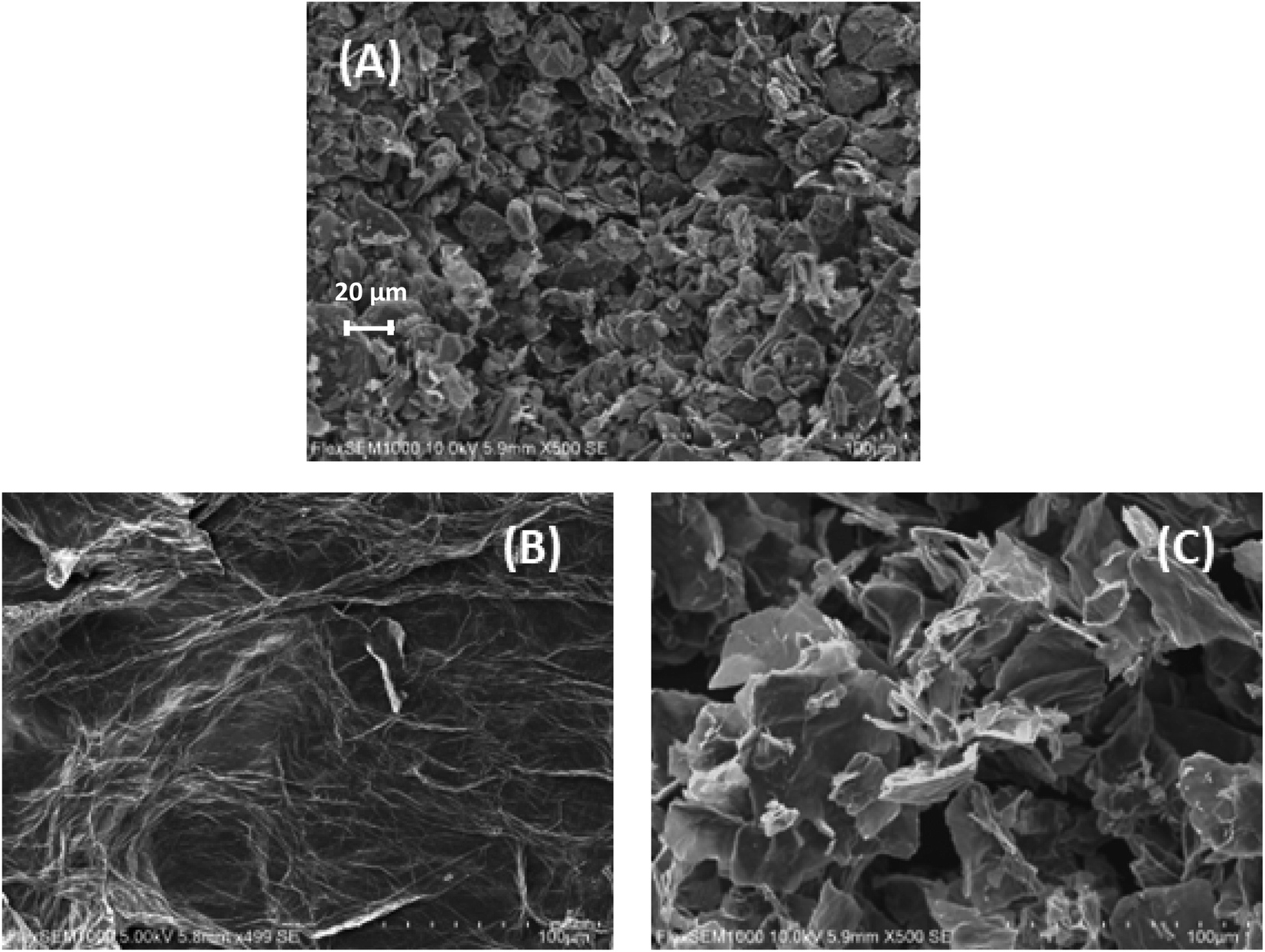 | ||
| Fig. 3 Scanning electron microscopy (SEM) images of (A) graphite, (B) GO and (C) NMDG@GO, with 500× of magnification. | ||
The FTIR spectra of GO and NMDG@GO are presented in Fig. 4. As can be seen, the GO spectrum showed a broad band at 3280 cm−1, related to the stretching of the O–H bond. Other characteristic bands of GO were observed in the spectrum, such as the band at 1720 cm−1, related to the stretching of the carbonyl double bond C![[double bond, length as m-dash]](https://www.rsc.org/images/entities/char_e001.gif) O, the band at 1588 cm−1 related to the stretching in-plane of the double bond CC, and the characteristic bands of the stretching of the C–O bond, which appeared at 1364 cm−1 and 1055 cm−1, related to epoxy and alkoxy groups, respectively.16,31,33 The occurrence of these bands means that the graphene was satisfactorily oxidated. In the NMDG@GO spectrum, the band at 3280 cm−1 was not as intense, as well as the bands at 1364 and 1055 cm−1, indicating a decrease in the amount of oxygen functional groups on the surface of the material, possibly due to the binding of NMDG to the structure. The typical band related to the stretching of the C–N bond was observed at 1190 cm−1,35 providing strong evidence of the binding of NMDG molecules to the GO structure, which was confirmed by elemental analysis, which showed the presence of 3.44% of nitrogen in the functionalized material, whereas the GO only presented residual amounts of this element.
O, the band at 1588 cm−1 related to the stretching in-plane of the double bond CC, and the characteristic bands of the stretching of the C–O bond, which appeared at 1364 cm−1 and 1055 cm−1, related to epoxy and alkoxy groups, respectively.16,31,33 The occurrence of these bands means that the graphene was satisfactorily oxidated. In the NMDG@GO spectrum, the band at 3280 cm−1 was not as intense, as well as the bands at 1364 and 1055 cm−1, indicating a decrease in the amount of oxygen functional groups on the surface of the material, possibly due to the binding of NMDG to the structure. The typical band related to the stretching of the C–N bond was observed at 1190 cm−1,35 providing strong evidence of the binding of NMDG molecules to the GO structure, which was confirmed by elemental analysis, which showed the presence of 3.44% of nitrogen in the functionalized material, whereas the GO only presented residual amounts of this element.
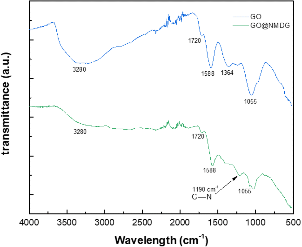 | ||
| Fig. 4 FTIR spectra for GO and NMDG@GO. | ||
Thermogravimetric analysis was used to assess the mass loss of the materials with increasing applied temperature in a nitrogen atmosphere to avoid oxidation reactions. In the case of graphite, no significant mass loss was observed, possibly due to the stability of its structure characterized by strong interlayer bonds (Fig. 5). In both GO and NMDG@GO, three distinct mass loss events were observed at different temperatures. The first mass loss was related to the removal of adsorbed water and the decomposition of epoxy groups, occurring around 100 °C. The second loss of mass, occurring between 180–210 °C, was attributed to the evolution of CO, CO2, and NO2, in the case of the functionalized material. The third loss of mass, occurring in the temperature range of 300–500 °C, indicated the decomposition of carbon rings in both materials.32,33 The difference in the mass loss between the materials, in the three stages, indicated that the functionalized GO presented stronger internal bonds than the non-functionalized GO since the loss of mass verified in the thermogravimetric analysis of NMDG@GO was smaller than in the case of GO. This same observation was previously reported by Caliman et al.32 when graphene oxide was modified with other amines.
 | ||
| Fig. 5 Thermogravimetric (TG) analysis of graphite, GO and NMDG@GO. | ||
3.2. Optimization of boron adsorption
The optimization of boron adsorption parameters was carried out using aqueous solutions (in deionized water) at a boron concentration of 3.0 mg L−1 and using produced water to investigate the influence of the sample's matrix. Three factors that could affect the solute removal efficiency were optimized in this study: (i) the mass of the adsorbent (NMDG@GO), (ii) the agitation time, and (iii) the pH of the medium. The levels of the factors were optimized using a central composite design (CCD). Seventeen experiments were conducted, encompassing 3 replicates at the central point, 6 experiments at the axial points of the design, and 8 experiments in the factorial region (2n, where n = the number of factors). The experimental planning, as well as the coded values and the results obtained, are shown in Table 2. Data analysis was performed using Statistica software, version 7.| Experiment | Mass (mg) | Time (min) | pH | B removal (%) |
|---|---|---|---|---|
| 1 | 30.00 (−1) | 20 (−1) | 4 (−1) | 56.74 |
| 2 | 100.00 (1) | 20 (−1) | 4 (−1) | 91.47 |
| 3 | 30.00 (−1) | 60 (1) | 4 (−1) | 60.58 |
| 4 | 100.00 (1) | 60 (1) | 4 (−1) | 99.15 |
| 5 | 30.00 (−1) | 20 (−1) | 10 (1) | 23.64 |
| 6 | 100.00 (1) | 20 (−1) | 10 (1) | 33.70 |
| 7 | 30.00 (−1) | 60 (1) | 10 (1) | 18.78 |
| 8 | 100.00 (1) | 60 (1) | 10 (1) | 33.69 |
| 9 | 65.00 (0) | 40 (0) | 7 (0) | 64.55 |
| 10 | 65.00 (0) | 40 (0) | 7 (0) | 68.47 |
| 11 | 65.00 (0) | 40 (0) | 7 (0) | 61.91 |
| 12 | 6.13 (−1682) | 40 (0) | 7 (0) | 22.43 |
| 13 | 123.87 (1682) | 40 (0) | 7 (0) | 72.67 |
| 14 | 65.00 (0) | 6 (−1682) | 7 (0) | 67.54 |
| 15 | 65.00 (0) | 74 (1682) | 7 (0) | 67.89 |
| 16 | 65.00 (0) | 40 (0) | 2 (−1682) | 64.40 |
| 17 | 65.00 (0) | 40 (0) | 12 (1682) | 26.45 |
After data analysis, it was found that only adsorbent mass and pH had a significant effect on the response (percentage of boron removal), as shown in the Pareto chart of standardized effects (Fig. 6) and the analysis of variance (ANOVA) table (Table 3). The generated full model was tested for lack-of-fit and the normality of residuals. No lack-of-fit of the model was observed, and the model residues exhibited a normal distribution, according to the Shapiro–Wilk test (W = 0.9885, n = 17). Both tests were performed at a 95% confidence level and confirmed that the model is suitable for predicting the percentage of boron removal based on the selection of the adsorbent mass used and the pH of the medium.
 | ||
| Fig. 6 Pareto chart of the standardized effects obtained in the multivariate optimization of boron removal from aqueous medium using a Central Composite Design (CCD). The factors under study were: pH, adsorbent (NMDG@GO) mass and agitation time. | ||
| Factor | Sum of squares | df | Mean square | F-Value | p-Value |
|---|---|---|---|---|---|
| Mass (L) | 2445.86 | 1 | 2445.86 | 224.49 | 0.0044 |
| Mass (Q) | 443.48 | 1 | 443.48 | 40.70 | 0.0237 |
| Time (L) | 3.809 | 1 | 3.809 | 0.3496 | 0.6142 |
| Time (Q) | 8.237 | 1 | 8.237 | 0.7560 | 0.4762 |
| pH (L) | 5039.96 | 1 | 5039.96 | 462.60 | 0.0022 |
| pH (Q) | 559.61 | 1 | 559.61 | 51.364 | 0.0189 |
| Mass × time | 9.440 | 1 | 9.440 | 0.8664 | 0.4502 |
| Mass × pH | 291.97 | 1 | 291.97 | 26.799 | 0.0353 |
| Time × pH | 33.579 | 1 | 33.579 | 3.082 | 0.2212 |
| Lack-of-fit | 613.09 | 5 | 122.62 | 11.255 | 0.0836 |
| Pure error | 21.790 | 2 | 10.895 |
Although the full model presented a good fit, one can consider that the mathematical model must be parsimonious, and, therefore, the model was recalculated by removing the non-significant factors (agitation time and the interactions of time–mass and time–pH) and, once again, no lack-of-fit was observed (Table 4). Moreover, residues followed a normal distribution according to the Shapiro–Wilk test at a 95% confidence level (W = 0.9824, n = 17), and the adjusted r2 parameter was equal to 0.9961, confirming the ability of the model to predict boron removal based on the pH of the medium and the adsorbent mass used. The fitted model is presented in eqn (3).
| R(%) = −2.806 + 1.477m − 0.0053m2 + 8.842pH − 0.8236pH2 − 0.0575m × pH | (3) |
| Factor | Sum of squares | df | Mean square | F-Value | p-Value |
|---|---|---|---|---|---|
| Mass (L) | 2445.86 | 1 | 2445.86 | 224.49 | 0.0044 |
| Mass (Q) | 527.09 | 1 | 527.09 | 48.379 | 0.0200 |
| pH (L) | 5039.96 | 1 | 5039.96 | 462.60 | 0.0022 |
| pH (Q) | 658.28 | 1 | 658.28 | 60.421 | 0.0162 |
| Mass × pH | 291.97 | 1 | 291.97 | 26.799 | 0.0353 |
| Lack-of-fit | 668.16 | 9 | 74.240 | 6.814 | 0.1345 |
| Pure error | 21.790 | 2 | 10.895 |
Using this model, the optimized adsorption condition was achieved at an adsorbent mass of about 120 mg, a pH of 2.0, and an extraction time of 40 min (response surface plot presented in Fig. 7). The optimized value for the adsorbent mass corresponded to the maximum axial value from the experiment, as expected since a greater mass of material results in higher availability of active sites for solute adsorption. Regarding the pH, boric acid (H3BO3; pKa = 9.2) is the predominant form of boron at pH 2.0, and, according to Bhagyaraj et al.,2 when found at concentrations below 220 ppm (as in this case), boric acid binds to NMDG diol with the formation of a stable 5-membered ring, as shown in Fig. 8. This justifies higher boron extraction at pH 2.0.
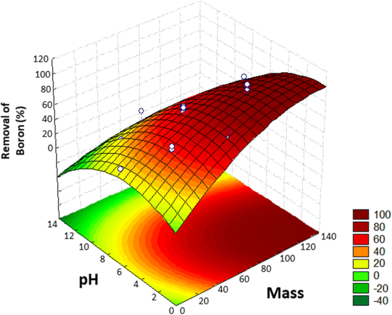 | ||
| Fig. 7 Response surface obtained in the Central Composite Design (CCD) for the removal of boron from aqueous medium. | ||
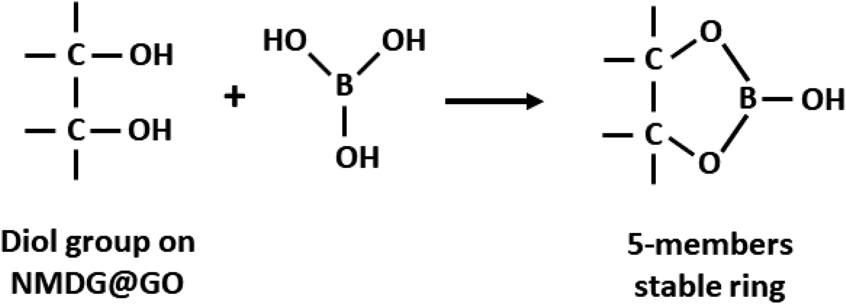 | ||
| Fig. 8 Schematic representation of boron adsorption by NMDG@GO through of diol group present in the NMDG molecule. | ||
The same central composite design was executed using produced water (PWC) to investigate the potential influence of the saline matrix on the adsorption process. The PWC sample was diluted 20 times to adjust the boron concentration to approximately 3.5 mg L−1, a boron concentration similar to that in experiments conducted in deionized water. The obtained results (optimal values) were similar to those observed in deionized water (adsorbent mass = 120 mg, pH = 2.0, and time = 40 min), indicating that the adsorption process in a saline medium is similar to that observed in pure water. However, it was noted that the percentages of boron removal in the saline medium were systematically lower than those observed in deionized water, indicating that the matrix effect does not alter the adsorption mechanism but affects the efficiency of the process.
During the optimization of the adsorption conditions, desorption tests were conducted to test the recovery of boron from the solid phase. In this experiment, elution was performed with both 1.0 mol per L HCl and 0.05 mol per L NaOH solutions. The elution with HCl solution resulted in the recovery of only 10 to 25% of boron, whereas the recovery of boron was even worse (0 to 11%) when elution was carried out with the NaOH solution. Consequently, the unique approach viable to recover (desorb) boron from the material involved the total digestion of the loaded material in a microwave oven with concentrated HNO3, as mentioned in section 2.6. Total digestion provided a quantitative release of the adsorbed boron (>90% recovery).
3.3. Adsorption isotherms
Adsorption isotherms are tools capable of quantitatively describing the capacity of the adsorbent to retain the solute under equilibrium conditions.36 Initially, the Nernst partition equation (eqn (4)) was tested. The results showed a linear relationship between the amount of boron retained on the adsorbent (qe) and its remaining concentration in the solution at equilibrium (Ce). Fig. 9 illustrates this relationship as a straight line with an r2 value of 0.9667 and a slope of 0.0564 L g−1, which represents the boron partition constant (Kd) between the two phases.
 | (4) |
 | ||
| Fig. 9 Nerst adsorption isotherm for boron in aqueous medium using NMDG@GO as an adsorbent. | ||
After the preliminary assessment using the Nernst partition law, the Langmuir and Freundlich isotherms were tested, as they provide a more appropriate description of adsorption processes and can estimate various parameters related to the adsorption process. The Langmuir isotherm was first tested. It is essential to remember that this isotherm has some requirements for data to fit satisfactorily: (i) adsorption should occur in a monolayer, (ii) no interaction should occur between solute molecules when adsorbed on the solid phase, (iii) the active sites of the adsorbent should have identical adsorption capacities.36,37 The linearized form of the Langmuir isotherm is expressed in eqn (5).
 | (5) |
Modeling the data using the Langmuir isotherm resulted in an r2 value of 0.0619, clearly showing that it is not possible to describe the system's behavior using this isotherm. Certainly, one or more restrictions of this isotherm were not met in the adsorption process under study.
Since the data did not fit the Langmuir isotherm, the Freundlich isotherm was tested. This isotherm describes the behavior of heterogeneous systems where adsorption can occur in multiple layers.36 The linearized equation of the Freundlich isotherm is shown in eqn (6):
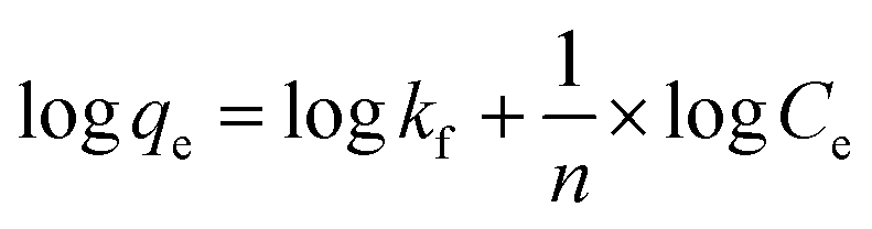 | (6) |
The application of the Freundlich isotherm to the data obtained in the boron adsorption by NMDG@GO showed a linear behavior with an r2 value of 0.9368 and a value of 1/n equal to 0.89, indicating that the solute has a greater affinity for the adsorbent than for the liquid phase.38 Based on these data, it can be concluded that the adsorption of boron by NMDG@GO is favorable and likely occurs in multiple layers and on the heterogeneous surface of the material. This conclusion is consistent with the data shown in Fig. 9, which indicates that even at high boron concentrations, the adsorbent did not reach its maximum adsorption capacity. This suggests that multiple adsorption mechanisms may be occurring, related to both chemical adsorption (as proposed earlier) and physical adsorption in multiple layers.
In this context, the model that best explained the boron adsorption process with the proposed material was the Nernst partition equation (eqn (5)). By plotting the Ce (mol L−1) versus qe (mol g−1), a straight line with an r2 value of 0.9667 (Fig. 9) was obtained, indicating that the mass of solute adsorbed per unit mass of adsorbent is proportional to the solute concentration in the liquid phase. In other words, the adsorption process occurs in a way that maintains equilibrium between the amount of solute in the liquid phase and the amount of solute retained in the solid phase. Interestingly, this fact may explain why the maximum adsorption capacity of the adsorbent was not reached even when experiments were conducted with concentrations much higher than those naturally found in the environment (boron concentration up to 1000 mg L−1 was tested).
3.4. Adsorption kinetics
Adsorption kinetics is the study of the rate of mass transfer of the solute from the liquid phase into the interior of the adsorbent particle over time. In general, adsorption kinetics can be evaluated using the pseudo-first-order and pseudo-second-order models, which can be described by eqn (7) and (8), respectively.
 | (7) |
 | (8) |
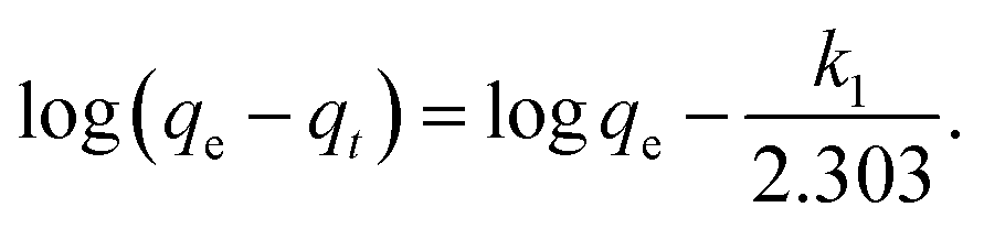
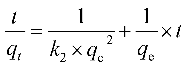
The application of the pseudo-first-order model to the obtained data showed a reasonable fit of the data to the model, as the coefficient of determination (r2) values of the curves were always greater than 0.94 (Table 5). However, the predictive capability of this model was limited, as the observed differences between the predicted qe and the observed qe were always greater than 20%. On the other hand, the application of the pseudo-second-order model generated models with even higher coefficients of determination (r2) than those observed in the pseudo-first-order model (>0.98) and superior predictive capability. In this case, the observed differences between the predicted qe and the observed qe ranged between 8 and 17% (Table 6). Therefore, the process that best modeled data was the pseudo-second-order kinetics since, in this case, predicted values were closer to the experimental values than in the case of pseudo-first order model.
| Parameter | Initial concentration of boron (mg L−1) | ||
|---|---|---|---|
| 5 | 25 | 50 | |
| r2 | 0.9413 | 0.9813 | 0.9982 |
| k | −0.05 | −0.12 | −0.18 |
| qe predicted | 11.2 | 35.0 | 55.7 |
| qe observed | 17.4 | 45.9 | 71.0 |
| Difference (%) | 36 | 24 | 22 |
| Parameter | Initial concentration of boron (mg L−1) | ||
|---|---|---|---|
| 5 | 25 | 50 | |
| r2 | 0.9862 | 0.9926 | 0.9937 |
| k | 0.0070 | 0.0032 | 0.0057 |
| qe predicted | 19.9 | 53.5 | 76.9 |
| qe observed | 17.4 | 45.9 | 71.0 |
| Difference (%) | −14 | −17 | −8 |
In general, the processes that control the adsorption rate are (i) the mass transport of the analyte from the solution to the interface of the adsorbent particle with the solution, which tends to be minimized through efficient system agitation; (ii) interfacial diffusion, which is related to the diffusion of the solute through the interfacial film, whose resistance can be evaluated; and (iii) intraparticle diffusion, which is related to the diffusion of the solute that reaches the adsorbent surface (after diffusing through the interfacial film) into the pores of the material. The application of the Morris–Weber kinetic model can provide information about the occurrence (or not) of a diffusive process during solute adsorption. Thus, this model was tested, as described in eqn (9).
 | (9) |
In all conducted experiments, values of C greater than 1 were obtained, indicating that there is resistance to solute diffusion at the interface of the material. However, intraparticle diffusion was ruled out because graphene oxide (GO) is a material with atomic thickness and is considered a 2D material. Therefore, intraparticle diffusion models were not tested, as these models specifically study diffusion within the pores of the material. In front of this scenario, it is possible to conclude that the interfacial film diffusion is the process that controls the adsorption rate of boron by NMDG@GO.
3.5. Application
The new material proposed in this study was tested for the adsorption of boron present in waters originating from petroleum exploration, supplied by Petrobras. Three samples of production waters (PWA, PWB, and PWC) and one sample of formation water (FW) were tested. Boron removal experiments were conducted using previously optimized adsorption conditions, and boron concentrations in the solutions were determined by MIP OES. It is important to note that the masses of boron removed from the solution were estimated by determining the boron retained on the NMDG@GO after its microwave-assisted acid digestion. The percentage of boron removal (R) was calculated according to eqn (10).
 | (10) |
The results obtained in this experiment are shown in Table 7, along with information about the tested samples. The percentages of boron removal ranged from 22% to 35%. These values contrast with the removal percentages obtained in the optimization experiments with deionized water, which reached values higher than 90%. These differences are certainly due to the high complexity of the sample matrices, which, in addition to containing dissolved organic substances, have high salinities.
| Sample | Salinity (‰) | Cia (mg L−1) | Initial mass of boron in solution (μg) | Adsorbed mass of boron (μg) | Boron removal (%) |
|---|---|---|---|---|---|
| a Ci is the initial concentration of boron in the sample. | |||||
| FW | 9 | 10.47 ± 1.05 | 104.7 | 23.03 | 22 ± 2 |
| PWA | 30 | 4.80 ± 0.01 | 48.0 | 14.88 | 31 ± 5 |
| PWB | 65 | 26.46 ± 0.01 | 264.6 | 92.61 | 35 ± 2 |
| PWC | 220 | 71.49 ± 0.01 | 714.9 | 207.32 | 29 ± 1 |
Applying the Nernst partition equation to the analyzed saline samples, and plotting the initial boron concentration against the retained mass of boron, it was evident that the model fits the data well (r2 = 0.9881). For instance, when the initial boron concentration was 71.49 mg L−1 (PWC sample), the adsorbed mass on the material was 207.32 μg (Table 7), which significantly exceeds the initial masses of boron present in the PWA, PWB, and FW samples. This behaviour confirmed that the boron adsorption process with NMDG@GO is dependent on the equilibrium between boron concentration in the liquid phase and boron adsorbed on the solid phase. Additionally, it could be verified that the salinity of the samples affected this equilibrium, through the reduction of the percentage of boron removed by the material compared to the boron removed in a boron solution without the presence of other ions (no saline solution). On the other hand, the concentration of salts did not alter the adsorption process significantly as can be evidenced by removal percentages ranging from 29 to 35% in production waters, despite the difference among the salinities (30 to 220‰). This behavior is consistent with what was observed in the construction of the isotherms, where the system under study followed the Nernst partition law.
4. Conclusions
In this study, a new material was developed for boron removal in water. It was prepared by functionalizing graphene oxide with N-methyl-D-glucamine and successfully characterized using various analytical techniques.The adsorption of boron in aqueous media was optimized through a multivariate process with a central composite design (CCD). The pH of the medium and the mass of the adsorbent had a significant effect on boron removal in solution, while the agitation time was not relevant in the range of 6 to 74 min (the studied interval).
The adsorption process was characterized from both a kinetic and equilibrium standpoint under the optimized conditions. The transfer of the solute from the solution to the adsorbent followed a pseudo-second-order kinetics and could be modeled using the Freundlich isotherm. The adsorption process seems to occur heterogeneously in multilayers, suggesting that both chemical and physical sorption may be occurring simultaneously. Even at high boron concentrations in solution, it was not possible to reach the maximum sorption capacity of the material. This can be explained by the Nernst partition equation, which demonstrated that the boron adsorption process with NMDG@GO was governed by an equilibrium between the solute concentration in the solution and the amount retained in the proposed material.
The developed material was applied for boron removal from saline waters originating from petroleum exploration. It was tested for boron removal from three samples of production waters and one sample of formation water, with varying salinities and boron concentrations. The removal percentages ranged from 22% to 35%. The amounts retained were found to be dependent on the initial boron concentration in solution, following the Nernst partition law.
Conflicts of interest
The authors declare that they have no known competing financial interests or personal relationships that could have appeared to influence the work reported in this paper.Acknowledgements
The authors would like to thank for the financial support of Fundação Carlos Chagas Filho de Amparo à Pesquisa do Estado do Rio de Janeiro (E-26/201.127/2022, E-26/200.201/2023, E-26/010.002212/2019), Conselho Nacional de Desenvolvimento Científico e Tecnológico (Proc. 317085/2021-2, Proc. 306787/2022-9) and the scholarship granted by Coordenação de Aperfeiçoamento de Pessoal de Nível Superior – Brazil (CAPES) – Finance code 001.References
- S. Akdag, R. Keyikoglu, A. Karagunduz, B. Keskinler, A. Khataee and Y. Yoon, Appl. Clay Sci., 2023, 233, 106814 CrossRef CAS.
- S. Bhagyaraj, M. A. Al-Ghouti, P. Kasak and I. Krupa, Emergent Mater., 2021, 4, 1167–1186 CrossRef CAS.
- C. Resgalla Jr, L. M. Mansor, D. C. Vieira, J. Pereira and C. M. Radetski, Chemosphere, 2022, 288, 132595 CrossRef PubMed.
- X. W. Liu, C. J. Xu, P. Chen, K. X. Li, Q. K. Zhou, M. M. Ye, L. Zhang and Y. Lu, Int. J. Environ. Res. Public Health, 2022, 19, 10671 CrossRef CAS PubMed.
- A. Siciliano, C. Limonti, G. M. Curcio and F. Marchio, J. Water Proc. Eng., 2022, 50, 103310 CrossRef.
- European Parliament, European Union (EU). Boron concentration limit for water intended for human consumption in Europe, 2011, https://www.europarl.europa.eu/doceo/document/E-7-2011-010115_EN.html, accessed on 14th October 2023.
- WHO (World Health Organization), Boron in drinking water, guidelines for drinking-water quality, 2009, https://www.who.int/docs/default-source/wash-documents/wash-chemicals/boron-chemical-fact-sheet.pdf?sfvrsn=a936384f_4, accessed on 14th October 2023.
- CONAMA (Conselho Nacional do Meio Ambiente), 2005, Resolução No 357, de 17 de março de 2005, https://www.icmbio.gov.br/cepsul/images/stories/legislacao/Resolucao/2005/res_conama_357_2005_classificacao_corpos_agua_rtfcda_altrd_res_393_2007_397_2008_410_2009_430_2011.pdf, accessed on 14th October 2023.
- CONAMA (Conselho Nacional do Meio Ambiente), 2008, DOI:10.1016/j.mtcomm.2022.103611, Resolução No 397, de 03 de abril de 2008, https://agencia.baciaspcj.org.br/docs/resolucoes/resolucao-conama-397.pdf, accessed on 14th October 2023.
- CONAMA (Conselho Nacional do Meio Ambiente), 2011, Resolução No 430, de 13 de maio de 2011, https://www.legisweb.com.br/legislacao/?id=114770, accessed on 14th October 2023.
- Y. W. Du, X. R. Zhang, C. P. Cao, J. B. Dai, Q. Y. Gong, D. X. Zhang, H. N. Deng and L. X. Xie, Desalination, 2023, 546, 116178 CrossRef CAS.
- B. Ozbey-Unal, D. Y. Imer, B. Keskinler and I. Koyuncu, Desalination, 2018, 433, 141–150 CrossRef CAS.
- P. Cyganowski, F. Sen, E. Altiok, J. Wolska, M. Bryjak, N. Kabay, M. Arda and M. Yuksel, Solvent Extr. Ion Exch., 2021, 39, 584–603 CrossRef CAS.
- T. T. Sun, F. L. Li, Q. K. Zhang, X. L. Geng, H. W. Chen and Q. Zhao, Water, 2022, 14, 1212 CrossRef CAS.
- A. Y. Goren, Y. K. Recepoglu, A. Karagunduz, A. Khataee and Y. Yoon, Chemosphere, 2022, 293, 133587 CrossRef PubMed.
- N. Al-Afy and H. Sereshti, Desalin. Water Treat., 2019, 153, 65–75 CrossRef CAS.
- Y. Zhang, X. Liang, T. Jiang, Z. Chen and X. Ji, Mater. Today Commun., 2022, 31, 103611 CrossRef CAS.
- S. Mehanathan, J. Jaafar, A. M. Nasir, R. A. Rahman, A. F. Ismail, R. M. Illias, M. H. D. Othman, M. A. Rahman, M. R. Bilad and M. N. Naseer, Membranes, 2022, 12, 798 CrossRef CAS PubMed.
- O. Kaftan, M. Açikel, A. E. Eroglu, T. Shahwan, L. Artok and C. Ni, Anal. Chim. Acta, 2005, 547, 34–41 CrossRef.
- T. Delazare, L. P. Ferreira, N. F. P. Ribeiro, M. M. V. M. Souza, J. C. Campos and L. Yokoyama, J. Environ. Sci. Health, Part A, 2014, 49, 923–932 CrossRef CAS PubMed.
- J. G. Neo, S. Japip, L. Luo, T. Chung, M. Weber and C. Maletzko, Sep. Purif. Technol., 2019, 222, 214–220 CrossRef CAS.
- T. Chen, Q. Wang, J. Lyu, P. Bai and X. Guo, Sep. Purif. Technol., 2020, 231, 115930 CrossRef CAS.
- J. Bao, T. Zhang, S. Wu, X. Li, W. Li, C. Liu, J. Li and R. Lu, J. Hazard. Mater., 2023, 460, 132460 CrossRef CAS PubMed.
- Z. B. Ocal, M. S. Oncel, B. Keskinler, A. Khataee and A. Karagunduz, Process Saf. Environ. Prot., 2024, 182, 719–726 CrossRef CAS.
- J. Ulatowska, I. Polowczyk, A. Bastrzyk, T. Kozlecki and W. Sawinski, Sep. Sci. Technol., 2020, 55, 2149–2157 CrossRef CAS.
- T. Sun, F. Li, Q. Zhang, X. Geng, H. Chen and Q. Zhao, Water, 2022, 14, 1212 CrossRef CAS.
- O. Eljamal, I. Maamoun, S. Alkhudhayri, R. Eljamal, O. Falyouna, K. Tanaka, N. Kozai and Y. Sugihara, J. Water Proc. Eng., 2022, 46, 102608 CrossRef.
- S. Eigler and A. Hirsch, Angew Chem. Int. Ed. Engl., 2014, 53, 7720–7738 CrossRef CAS PubMed.
- K. S. Novoselov, A. K. Geim, S. V. Morozov, D. Jiang, Y. Zhang, S. V. Dubonos, I. V. Grigorieva and A. A. Firsov, Science, 2004, 306, 666–669 CrossRef CAS PubMed.
- Y. Liu, H. Y. Huang, D. F. Gan, L. R. Guo, M. Y. Liu, J. Y. Chen, F. J. Deng, N. G. Zhou, X. Y. Zhang and Y. Wei, Ceram. Int., 2018, 44, 18571–18577 CrossRef CAS.
- C. P. P. Soares, R. L. Baptista and D. V. Cesar, Mater. Res., 2018, 21, e20170726 Search PubMed.
- C. C. Caliman, A. F. Mesquita, D. F. Cipriano, J. C. C. Freitas, A. A. C. Cotta, W. A. A. Macedo and A. O. Porto, RSC Adv., 2018, 8, 6136–6145 RSC.
- Z. Zhang, H. C. Schniepp and D. H. Adamson, Carbon, 2019, 154, 510–521 CrossRef CAS.
- L. A. Pérez, N. Bajales and G. Lacconi, Appl. Surf. Sci., 2019, 495, 143539 CrossRef.
- H. Gunzler, and H. U. Gremlich, IR Spectroscopy – An Introduction, Wiley-VCH Verlag, Weinheim, Germany, 1st edn, 2002 Search PubMed.
- R. F. Nascimento, A. C. A. Lima, C. B. Vidal, D. Q. Melo, and G. S. C. Raulino, Adsorção: aspectos teóricos e aplicações ambientais, Editora UFC, Fortaleza, Brazil, 2014 Search PubMed.
- J. O. Vinhal, M. R. Lage, J. W. M. Carneiro, C. F. Lima and R. J. Cassella, J. Environ. Manage., 2015, 156, 200–208 CrossRef CAS PubMed.
- G. Crini and H. N. Peindy, Dyes Pigm., 2006, 70, 204–211 CrossRef CAS.
| This journal is © The Royal Society of Chemistry 2024 |