 Open Access Article
Tunable internal structure carbon sphere synthesis driven by water-solubility and its application in gas separation†
Yaqi Yaoab,
Hongying Zhuo*a,
Jinming Xu*a,
Xiaofeng Yanga and
Yanqiang Huang *a
*a
aState Key Laboratory of Catalysis, Dalian Institute of Chemical Physics, Chinese Academy of Sciences, No. 457 Zhongshan Road, Dalian 116023, China. E-mail: zhuohongying@dicp.ac.cn; xujm@dicp.ac.cn; yqhuang@dicp.ac.cn
bUniversity of Chinese Academy of Sciences, Beijing 100049, China
First published on 13th February 2024
Abstract
A method for synthesizing carbon spheres with a tunable particle size and internal structure from polyfurfuryl alcohol (PFA) was developed. By tuning the concentration of a structure directing agent (polypropylene glycol, PPG), we found a mechanism to tune the inner architecture of carbon spheres driven by water-solubility. A mixture of PFA and PPG transferred from the “water-in-oil” phase to an “oil-in-water” phase with an increasing content of PPG because of a difference in water-solubility between furfuryl alcohol (FA), PFA, and PPG. As a result, the internal morphology of the carbon sphere evolved from a “cheese-like” to a “pomegranate-like” structure, which was accompanied by an increasing specific surface area and pore volume. Furthermore, the separation of C2H2 and C2H3Cl was tested on the 25%-FACS (furfuryl alcohol-based carbon sphere) sample under different activation treatments with CO2 or CO2–NH3, with the coexisting “cheese-like” and “pomegranate-like” inner structures, owing to its moderate pore volume and mechanical strength. The maximum adsorption capacity of C2H3Cl reached 0.77 mmol g−1, while C2H2 was adsorbed in significantly lower quantities. It is believed that the high polarizability and high dipole moment of the C2H3Cl molecule primarily contribute to the excellent performance of C2H2 and C2H3Cl separation, and the introduction of polar N-containing groups on the carbon skeleton further promotes C2H3Cl adsorption.
1 Introduction
Carbon materials with various morphologies, including granular, powder, fiber, and sphere morphologies, find extensive applications in gas adsorption,1–4 hydrogen storage,5 catalysis,6–8 energy storage,9,10 and other fields. Compared with granular/powder/fiber carbon materials, carbon spheres are receiving considerable attention owing to their unique advantages of smooth surface, low pressure drop, good fluidity, high wear resistance, and mechanical properties, which are essential properties in practical applications.11–13 Consequently, considerable efforts have been devoted to the controllable synthesis of spherical carbon materials with tailored physical and chemical properties.14Millimeter-sized carbon spheres can be categorized into asphalt-based carbon spheres, coal-based carbon spheres, low-molecular-weight organic matter-based carbon spheres, and polymer-based carbon spheres based on the various precursors that are employed in their synthesis. Polymer materials, particularly resin materials, are extensively utilized in the synthesis of spherical activated carbon. Resin offers advantages such as a high carbon element content, uniform and controllable structure, and high mechanical strength, making it a highly valued precursor in the active carbon field. Among these, furfuryl alcohol (FA) derived from agricultural and sideline products supports low-carbon development and holds promising prospects for use in the production of various high-performance furan resins.15 Current research on the synthesis of furfuryl alcohol-derived carbon spheres predominantly focuses on size regulation,16–18 dispersion improvement,14 and morphology control.17 In addition, synthesized carbon spheres typically possess a homogeneous solid internal structure; however, few studies have been carried out to design and regulate the internal structure.
Internal structures play a pivotal role in determining the property and application of carbon spheres. In this study, polyfurfuryl alcohol (PFA) was used as a carbon precursor and polypropylene glycol (PPG) as a structure directing agent. By adjusting synthesis process parameters, carbon spheres with different internal structures were obtained. Thermogravimetric analysis (TG), N2 physical adsorption, Fourier transform infrared spectroscopy (FTIR), X-ray diffraction (XRD), and scanning electron microscopy (SEM) techniques were used to investigate the formation process of carbon spheres and the evolution of internal structures. Finally, the adsorption properties of C2H2 and C2H3Cl on the obtained carbon spheres were studied.
2 Experimental sections
2.1. Chemicals
Furfuryl alcohol (C5H6O2, (AR)) were purchased from Sinopharm Chemical Reagent Co., Ltd. Polypropylene glycol (>99.0%) was purchased from Shandong Yousuo Chemical Technology Co., Ltd. Polyvinyl alcohol ([C2H4O]n, (AR)) was purchased from Shanghai Aladdin Bio-Chem Technology Co., Ltd. Dodecylbenzene sulfonic acid (C18H30SO3, (AR)) was purchased from Shanghai Macklin Biochemical Co., Ltd.2.2. Synthesis of furfuryl alcohol-based carbon sphere
Firstly, 0.33 g maleic anhydride was dissolved in 250 g deionized water, then furfuryl alcohol and polypropylene glycol-2000 (PPG-2000) were added to the solution to pre-polymerize for 3 hours under 80 °C. Secondly, the pre-polymerized furfuryl alcohol resin (PFA) was mixed with 50 g water, 1.43 g 5% aqueous solution of polyvinyl alcohol (PVA), and 4.58 g 10% aqueous solution of dodecylbenzene sulfonic acid. After stirring for 30 min, the obtained mixture was cured at 95 °C for 3 hours. The furfuryl alcohol resin sphere (FARS) was obtained after filtration, washing, and air drying. Finally, the furfuryl alcohol resin sphere was carbonized at 800 °C for 30 min in the rotary tube furnace under an inert atmosphere to form the furfuryl alcohol-based carbon sphere (FACS).2.3. Structural tuning of FACS
To tune the internal structure of FACS, the amount and the molecular weight of the structure directing agent were systemically investigated. The total mass of furfuryl alcohol and PPG-2000 remain unchanged, the mass ratio of PPG-2000 to furfuryl alcohol was changed from 0 to 50% and named as X%-FACS (taking 25%-FACS for an example, the added amount of PPG-2000 was 37.5 g, and furfuryl alcohol was 112.5 g). Then, the molecular weight of PPG was changed to 1500 and 4000 while maintaining its content of 25%, named as 25%-FACS-1500 and 25%-FACS-4000, respectively. As the default molecular weight of PPG is 2000, so 2000 is not labeled in the following part of this paper unless when we talk about the influence of molecular weight. To tune the particle size of FACS, the amount of PVA (S: 0.96 g PVA; M: 1.43 g PVA; L: 2.86 g PVA, denoted as 25%-FACS-S, 25%-FACS-M, 25%-FACS-L) and pre-polymerization time (1, 2, 3 hours, named as 25%-FACS-1 h, 25%-FACS-2 h, 25%-FACS-3 h) were investigated.2.4. Activation of the 25%-FACS-2000 sample
The activation of FACS was carried out by physical activation in a tube furnace. The sample was placed in a quartz tube and activated for 1, 3, and 5 hours at 900 °C under CO2 atmosphere, denoted as 25%-FACS-CO2-T, T represents the activation time. In order to introduce N-groups to the carbon surface, a two-step activation method is adopted. The FACS is firstly treated with CO2 under 800 °C for 5 h, denoted as 25%-FACS-CO2. Then, the temperature was lowered to 600 °C, the gas was switched to NH3 at the same time, which was expressed as 25%-FACS-CO2-NH3-T, T (1, 2, and 3 hours), represents the NH3 treatment time.2.5. Characterization
The textural properties of FACS were tested on a Micromeritics ASAP 2460 physical adsorption instrument. The specific surface area calculated based on the BET model and micropore specific surface area and pore volume were determined using the t-plot method. The TG test was performed on the Q600 TG analyzer manufactured by TA Instruments, with the temperature increasing from room temperature to 900 °C under 100 mL min−1 Ar flow rate. FTIR analysis was obtained on a Bruker Tensor 27 spectrometer using KBr and 100![[thin space (1/6-em)]](https://www.rsc.org/images/entities/char_2009.gif) :
:![[thin space (1/6-em)]](https://www.rsc.org/images/entities/char_2009.gif) 1 compression of samples over a range of 4000–400 cm−1 with a scanning number of 32. Raman spectroscopy was conducted via a Micro Raman spectrometer of Renishaw Company. X-ray diffraction (XRD) patterns were analyzed by PANalytical X'Pert-Pro X-ray diffractometer in the 2θ range of 10–80°. The surface morphology of the material was characterized by JSM-7800F of Japan Electronics Corporation. Surface nitrogen species were characterized by X-ray photoelectron spectroscopy (XPS) on a Thermo Fisher ESCALAB 250Xi equipped with and Al Kα radiation source (hν = 1486.6 eV).
1 compression of samples over a range of 4000–400 cm−1 with a scanning number of 32. Raman spectroscopy was conducted via a Micro Raman spectrometer of Renishaw Company. X-ray diffraction (XRD) patterns were analyzed by PANalytical X'Pert-Pro X-ray diffractometer in the 2θ range of 10–80°. The surface morphology of the material was characterized by JSM-7800F of Japan Electronics Corporation. Surface nitrogen species were characterized by X-ray photoelectron spectroscopy (XPS) on a Thermo Fisher ESCALAB 250Xi equipped with and Al Kα radiation source (hν = 1486.6 eV).
2.6. Evaluation of adsorbents
The separation of C2H2 and C2H3Cl was performed in a fixed bed. 0.5 g carbon sphere adsorbent was put into a U-shaped quartz tube, then the adsorbent was purged with He at a flow rate of 200 mL min−1 for 1 hour in an oil bath at 100 °C to remove the impurities adsorbed on the carbon sphere. After cooling to 30 °C, the He was switched to the mixture gas of 1000 ppm C2H2 and 1000 ppm C2H3Cl and balanced with N2 at a flow rate of 100 mL min−1. The C2H2 and C2H3Cl signals in real-time were collected by online mass spectrometry (GAM200, IPI, Germany).3 Results and discussion
3.1. Synthesis of furfuryl resin micro-spheres
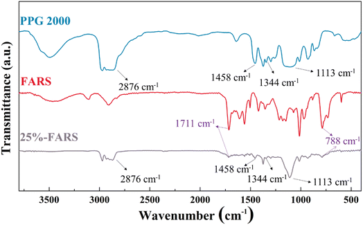
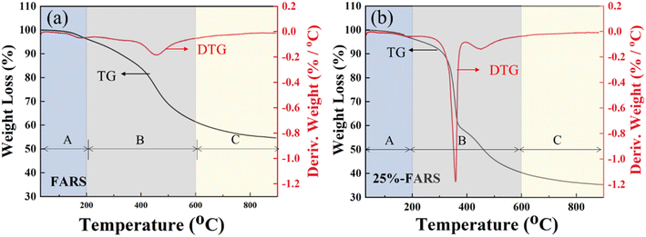
The polymerization of water-soluble furfuryl alcohol can be catalyzed by acid (maleic acid) through electrophilic substitution between the inter-molecular aromatic rings.19 As such, the red viscous but sparingly-soluble PFA can be acquired after a certain time of reaction at 80 °C. In addition, polyvinyl alcohol (PVA) was selected as the dispersant, which serves a kind of water-soluble polymer with hydrophilic hydroxyl group, and its long carbon chain facilitates the effective spatial dispersion of organic substances in the aqueous phase.20 This allows polyvinyl alcohol to envelop the PFA as spherical droplets, directly influencing the dispersion and stabilization of droplets in water. Ultimately, with the assistance of the curing agent (dodecylbenzene sulfonic acid) under elevated temperature, the spherical droplets undergo solidification, resulting in the formation of furfuryl alcohol resin sphere (FARS).The chemical composition of the FARS was firstly characterized by FTIR and TG analysis. Fig. 1 shows the FTIR results of pure FARS, PPG, and the representative 25%-FARS sample. The peaks at 1711 and 788 cm−1 belonging to the conjugated C![[double bond, length as m-dash]](https://www.rsc.org/images/entities/char_e001.gif) O and C
O and C![[double bond, length as m-dash]](https://www.rsc.org/images/entities/char_e001.gif) C bond vibration of γ-diketone in the hydrolysis furan rings, respectively, were observed in pure FARS and 25%-FARS samples, indicating the polymerization of FA. Meanwhile, the characteristic peaks of PPG at 2876, 1458, 1344, and 1113 cm−1 were detected in the 25%-FARS sample, suggesting the successful incorporation of PPG into FARS. Furthermore, the samples were subjected to testing in an Ar atmosphere using TG with the programmed temperature method. The weight loss process was delineated into three stages, as labeled in Fig. 2a and b. The weight loss below 200 °C was attributed to water removal (stage A), as observed in both the samples. In stage B (200–600 °C), the deoxygenation reaction of the C–O bond in five-membered heterocyclics occurred. Notably, the 25%-FARS sample exhibited an additional and sharp mass change rate at about 360 °C with a weight loss of nearly 25%. It can be explained as the decomposition of PPG in this sample. As the temperature rose above 600 °C, the carbonization process commenced (stage C), in this phase, the remaining chain carbon species with diene structure, undergoes a cyclization reaction to form the six-membered fused ring structure, which then further dehydrogenated to obtain the final FACS.21,22
C bond vibration of γ-diketone in the hydrolysis furan rings, respectively, were observed in pure FARS and 25%-FARS samples, indicating the polymerization of FA. Meanwhile, the characteristic peaks of PPG at 2876, 1458, 1344, and 1113 cm−1 were detected in the 25%-FARS sample, suggesting the successful incorporation of PPG into FARS. Furthermore, the samples were subjected to testing in an Ar atmosphere using TG with the programmed temperature method. The weight loss process was delineated into three stages, as labeled in Fig. 2a and b. The weight loss below 200 °C was attributed to water removal (stage A), as observed in both the samples. In stage B (200–600 °C), the deoxygenation reaction of the C–O bond in five-membered heterocyclics occurred. Notably, the 25%-FARS sample exhibited an additional and sharp mass change rate at about 360 °C with a weight loss of nearly 25%. It can be explained as the decomposition of PPG in this sample. As the temperature rose above 600 °C, the carbonization process commenced (stage C), in this phase, the remaining chain carbon species with diene structure, undergoes a cyclization reaction to form the six-membered fused ring structure, which then further dehydrogenated to obtain the final FACS.21,22
3.2. Size controlling of carbon sphere
Achieving precise size control, the optimal dispersion of carbon spheres is crucial for its practical applications, and this represents a key advantage of the polymer-based synthesis strategy employed in this work. Through the carbonization of FARS samples at 800 °C, we successfully produced carbon spheres with varying particle size by tuning the amount of PVA, which serves to prevent the resin spheres from clumping. PVA is a water-soluble polymer with hydrophilic hydroxyl groups, which is suitable for dispersing organic substances in the aqueous phase.23,24 As a dispersant, it can form single or multiple anchor points on the surface of organic particles, enhancing the adsorption stability and preventing easy dissolution. When the resin is stirred and dispersed into small droplets in the aqueous phase, PVA envelops around the droplets, preventing their aggregation into clusters. The long solvation chain of PVA creates sufficient three-dimensional barriers for effective spatial dispersion and stability. Therefore, as the quantity of PVA increases, the number of anchor points formed on the particle surface increases, resulting in smaller particle sizes. With the relatively lower usage of PVA, the particle size of FACS was observed to range from 30 to 60 meshes, with each size accounting for almost ∼30% (Fig. 3c and S2†). As the quantity of PVA increased, the particle size of FACS decreased, exhibiting a smaller particle size distribution. For instance, there were virtually no particles larger than 40 mesh, and the particles smaller than 60 mesh accounted for up to 70% in the 25%-FACS-L sample (Fig. 3i).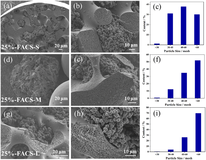 | ||
| Fig. 3 SEM images of the inside structure and the size distribution of (a–c) 25%-FACS-S, (d–f) 25%-FACS-M, (g–i) 25%-FACS-L. | ||
Additionally, the polymerization degree of PFA may also affect the size distribution of the carbon sphere. Varying the polymerization time resulted in corresponding changes in the particle size of carbon spheres. As illustrated in Fig. 4, almost all the carbon spheres were smaller than 60 mesh (Fig. 4 and Fig. S3†) when the polymerization time was set to 1 h. As the polymerization time is shortened, the particle size gradually decreases. The reason for this phenomenon is that the polymerization time becomes shorter, the molecular weight of the polymer becomes lower, and the viscosity of PFA decreases. At this time, the breakup of the droplets becomes easier and the size of the droplets becomes smaller.
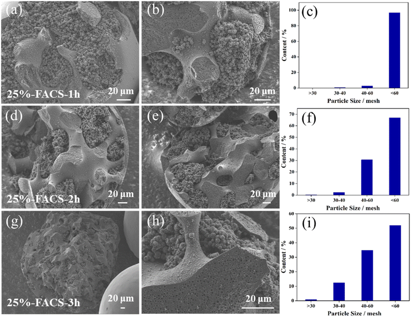 | ||
| Fig. 4 SEM images of the inside structure and the size distribution of (a–c) 25%-FACS-1 h, (d–f) 25%-FACS-2 h, (g–i) 25%-FACS-3 h. | ||
3.3. Internal morphology regulation for carbon sphere
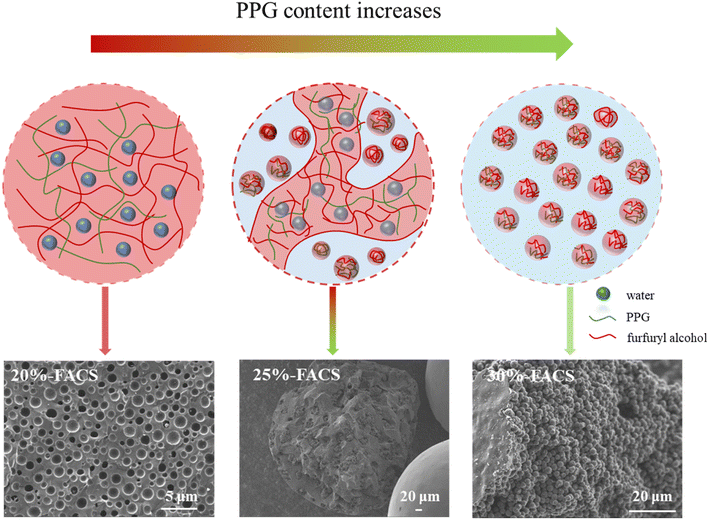
With the carbonization of the FARS samples at 800 °C, we obtained the carbon spheres FACS with a varied inner structure by adjusting the amount of the structure directing agent of PPG. Interestingly, while the particle shape of FACS remained largely unchanged with increasing PPG usage (Fig. 5), significant difference was observed in both the superficial layer and inner architecture of carbon spheres. With an increased proportion of PPG, the superficial layer exhibited an increasingly rough texture, and remarkable wrinkles can be found for the 50%-FACS sample. Notably, the inner architecture of carbon spheres underwent distinct transformations. The FACS without PPG displayed a transverse section similar to the superficial layer, featuring a smooth and uniform texture. In contrast, the transverse section of 20%-FACS presents a multi-hole structure like cheese (Fig. 5e and f). As the PPG proportion increased to 30% (Fig. 5j–l) and 50% (Fig. 5m–o), the carbon spheres show a distinct inner architecture with that of 20%-FACS, and it possesses a “pomegranate-like” structure through particle aggregation. In addition, a transition state between these two internal structures can be found, in which the “cheese-like” and “pomegranate-like” inner structure was found to be coexisting in the 25%-FACS sample (Fig. 5g–i).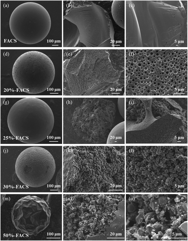 | ||
| Fig. 5 SEM images of the outside and inside surfaces of (a–c) FACS, (d–f) 20%-FACS, (g–i) 25%-FACS, (j–l) 30%-FACS, (m–o) 50%-FACS. | ||
Such an evolution of the inner architecture can be attributable to the differences and changes in the water-solubility of PPG and PFA with molecular weight. PPG with smaller molecular weight (e.g., PPG-400 and PPG-600) can be dissolved in water to form a homogeneous solution, but PPG with larger molecular weight (e.g., PPG-2000 and PPG-4000) can only be slightly soluble in water and two phases of oil and water are formed. Thus, as the molecular weight increases, the solubility of PPG in water decreases dramatically. The change in the PFA solubility with molecular weight in water is almost the same as PPG. In the three-component liquid phase system water–PPG–PFA, the equilibrium state of the PPG–PFA oil phase and water phase can change with variations in the initial composition. Drawing inspiration from this, it is reasonable to suspect that adjusting the solubility and ratio of the component could disrupt the original phase equilibrium, lead to changes in miscibility between components, and result in the formation of a new internal structure. Both PFA and PPG contain polyether bonds to facilitate their blending according to the principle of “like dissolves like”. As the molecular weight of PFA reaches a certain level, PFA and PPG separate from the water phase to form PPG–PFA oil phase droplets. When the PPG content is less than 20%, the liquid–liquid phase separation process with PPG requires a higher polymerization degree of PFA. As the polymerization of FA is a dehydration process between two molecules (eqn (1)), less water released by higher molecular weight PFA is introduced into the PPG–PFA droplets during the solidification, and finally “water-in-oil” structure similar to “cheese” is created, as shown in Fig. 6. When the content of PPG exceeds 30%, there is a lower requirement for the degree of polymerization of FA, leading to the release of more water by lower molecular weight PFA during the solidification stage. This results in the formation of “oil-in-water” phase in the PPG–PFA droplets, and a “pomegranate-like” internal structure is produced. When the conditions are between the above two situations, both the “oil-in-water” and the “water-in-oil” phases exist simultaneously in 25%-FACS.25–27
 | (1) |
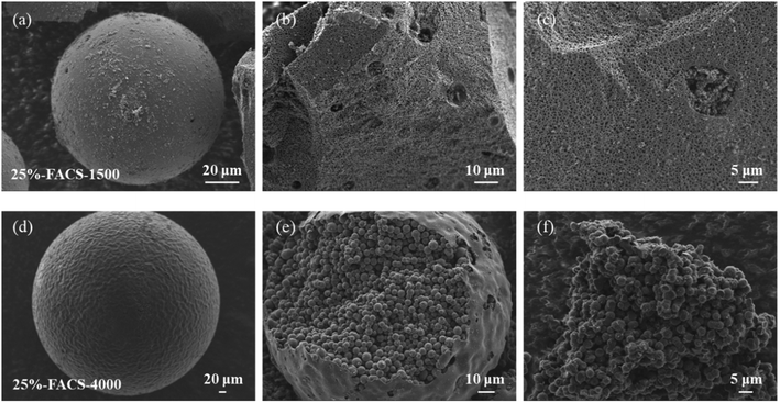
The molecular weight of PPG could also play an important role in the internal structure of carbon sphere. Fig. 7 shows the microstructure of 25%-FACS with different molecular weight of PPG (PPG-1500 and PPG-4000). Under the same dosage as PPG-2000, PPG-1500 leads to an inner structure of FACS composed with both the “cheese-like” and “pomegranate-like” structures, while the single phase “pomegranate-like” structure was only observed when the molecular weight of PPG-4000 was used (Fig. 7d–f). The solubility of PPG decreases with an increase in the molecular weight, indicating that higher molecular weight PPG promotes the liquid–liquid phase separation process; therefore, lower molecular weight PFA can introduce more water to the system and the “oil-in-water” phase forms in the drops of PPG–PFA.
3.4. Activation of carbon spheres
After carbonization, the carbon materials need to be activated to obtain a flourishing pore structure.28–31 Generally, there are two different ways for carbon activation: the physical and the chemical methods. In this work, carbon spheres were activated by high temperature heat treatment with CO2 or NH3, where the activation with CO2 aimed to improve the specific surface area of carbon spheres, while the nitridation through NH3 aimed to introduce N-containing functional groups onto the carbon surface.The activation of carbon spheres through partial gasification with CO2 involves the reversed Boudouard gasification reaction (C (s) + CO2 (g) = 2CO (g)) to generate the micropores of carbon spheres.32,33 The 25%-FACS sample was activated at 900 °C in CO2 atmosphere for 1, 3, and 5 hours (25%-FACS-CO2-1 h, 25%-FACS-CO2-3 h, and 25%-FACS-CO2-5 h), respectively, and their N2 physical adsorption isotherms are shown in Fig. 8a. All samples present the type I isotherms, indicative of a typical microporous material of the carbon sphere materials. Moreover, the adsorption capacity was significantly promoted with extended activation time. The surface area ranged from 691 to 1300 m2 g−1 as the activation time ranges from 1 to 5 hours, with the pore volume increasing from 0.27 to 0.51 cm3 g−1. The average pore size was estimated to be 0.56 nm (Table 1), while it still keeps its form of amorphous carbon, and no obvious graphitization was observed by XRD (Fig. 8b). Such a phase composition of carbon was also confirmed by the Raman spectrum. Peaks at 1360 and 1580 cm−1, corresponding to the D and G band in the carbon material, respectively, can be seen in Fig. 8c. Here, the G peak is ascribed to the stretching vibration of all sp2 atom pairs in the carbon ring or carbon chain, and the D peak represents the defects and disorders of carbon.34,35 The intensity ratio of the D and G peaks are widely used to measure the defect degree of carbon material,36,37 which are 0.97, 1.01, and 1.02 for the samples activated for 1, 3, and 5 hours, respectively, meaning a slight impact of activation time on the defect degrees of 25%-FACS-CO2 samples. The SEM result (Fig. S5†) showed that the activation time had no significant effect on the morphology of the materials. CO2 activation primarily enhances the micro-porous (<2 nm) of carbon spheres, while the changes at the micrometer scale remain unobservable at the resolution of the SEM.
 | ||
| Fig. 8 (a) N2 adsorption–desorption isotherms, (b) XRD patterns, and (c) Raman spectra of 25%-FACS-CO2 with different CO2 activation times. | ||
| Sample | SBET (m2 g−1) | Smicro (m2 g−1) | Vmicro (cm3 g−1) | V (cm3 g−1) | Pore size (nm) |
|---|---|---|---|---|---|
| 25%-FACS-CO2-1 h | 698 | 691 | 0.27 | 0.28 | 0.54 |
| 25%-FACS-CO2-3 h | 924 | 909 | 0.35 | 0.37 | 0.55 |
| 25%-FACS-CO2-5 h | 1320 | 1300 | 0.51 | 0.53 | 0.57 |
In addition, the doping of heteroatoms on the carbon skeleton, especially N-containing functional groups, has attracted great attention in carbon materials.38–41 This can modulate the surface alkalinity of carbon material and can be well realized through partial gasification with NH3. Here, in this work, the introduction of N species was achieved through a two-step method by calcining the activated carbon spheres with CO2 at 800 °C for 5 hours followed by an NH3 atmosphere at 600 °C (25%-FACS-CO2-NH3). The nitridation process only introduced N to the carbon skeleton but did not influence the pore structure of the carbon sphere, as evidenced by the N2 physical adsorption isotherms (Fig. 9a, S4† and Table 2). The elemental distribution characterized by EDS showed that the signal intensity of N species increased significantly with the activation time with NH3 and was uniformly distributed in the carbon spheres (Fig. 9e, h and k). To quantitatively analyze the surface nitrogen species, XPS analysis was performed. As shown in Fig. 9b, four N species coexisted, the peaks at 403.2 and 401.3 eV were attributed to nitrogen oxides and quaternary nitrogen species, and the peaks at 400.3 and 398.6 eV represent pyrrole nitrogen and pyridine nitrogen, respectively.39,42 The total nitrogen content varied from 1.41% to 2.57% (Table 3) with the increase in activation time with NH3.
| Sample | SBET (m2 g−1) | Smicro (m2 g−1) | Vmicro (cm3 g−1) | V (cm3 g−1) | Pore size (nm) |
|---|---|---|---|---|---|
| 25%-FACS-CO2 | 853 | 848 | 0.33 | 0.34 | 0.55 |
| 25%-FACS-CO2-NH3-1 h | 869 | 864 | 0.33 | 0.34 | 0.55 |
| 25%-FACS-CO2-NH3-2 h | 877 | 869 | 0.34 | 0.35 | 0.55 |
| 25%-FACS-CO2-NH3-3 h | 858 | 857 | 0.33 | 0.33 | 0.55 |
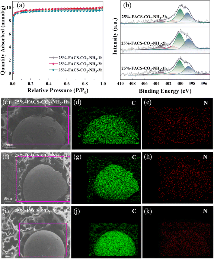 | ||
| Fig. 9 (a) N2 adsorption–desorption isotherms, (b) XPS N 1s spectra, (c–k) distribution of C and N elements of 25%-FACS-CO2-NH3 samples. | ||
| Sample | Npyridinca (%) | Npyrrolica (%) | Nquaternarya (%) | Noxidea (%) | Ncontentb (%) | Saturated time (min) | Breakthrough capacity (mmol g−1) |
|---|---|---|---|---|---|---|---|
| a Calculated from the XPS N 1s spectrum.b N content was measured using XPS. | |||||||
| 25%-FACS-CO2-NH3-1 h | 26.5 | 50.6 | 11.5 | 11.4 | 1.41 | 71 | 0.63 |
| 25%-FACS-CO2-NH3-2 h | 26.4 | 48.6 | 12.8 | 12.1 | 1.92 | 78 | 0.70 |
| 25%-FACS-CO2-NH3-3 h | 28.9 | 49.3 | 10.4 | 11.3 | 2.57 | 83 | 0.74 |
3.5. Adsorption property of carbon spheres toward C2H2 and C2H3Cl
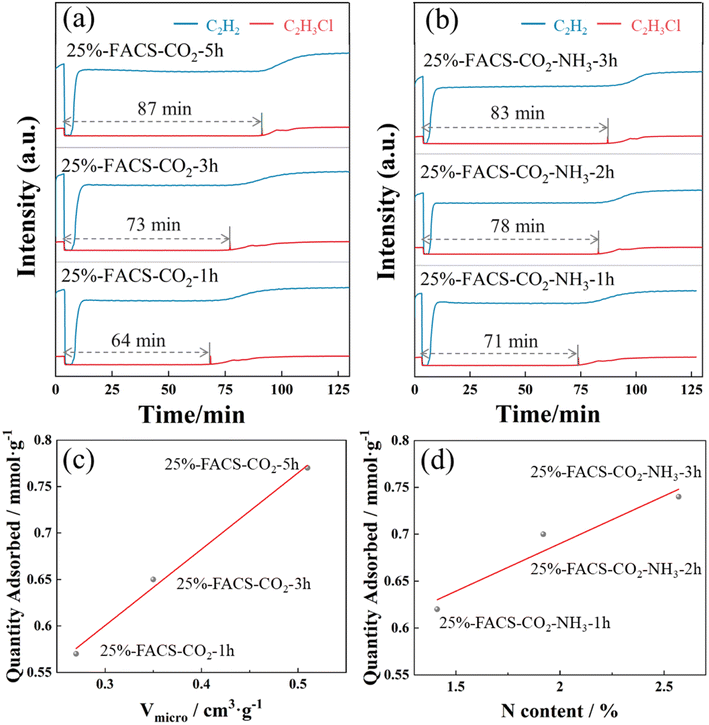
In the process of producing vinyl chloride through the acetylene hydrochlorination method, there is a significant amount of C2H3Cl and C2H2 in the exhaust gas. If these are directly emitted without treatment, they not only pollute the atmospheric environment but also pose a health risk to humans. Additionally, as crucial industrial raw materials, the direct emission of C2H3Cl and C2H2 would result in resource wastage. To enhance the utilization efficiency of vinyl chloride raw materials produced through the acetylene hydrochlorination method, it is necessary to separate and recover C2H3Cl and C2H2.43–45 Activated carbon is widely employed as a selective adsorbent owing to its abundant pore structures, substantial specific surface areas, and cost effectiveness.43,46The 25%-FACS sample with different activation methods, including one-step activation by CO2 and two-step activation by CO2–NH3, were used for the selective adsorption of C2H3Cl and C2H2. The corresponding breakthrough curves are shown in Fig. 10 and Table S3.† The results reveal that C2H2 cannot be adsorbed by either the 25%-FACS-CO2 or the 25%-FACS-CO2-NH3 samples, as evidenced by the short breakthrough time. While C2H3Cl can be adsorbed by both the samples, no C2H3Cl is detected until a breakthrough time as long as 64 min on 25%-FACS-CO2-1 h. Meanwhile, the pore volume of carbon spheres plays a crucial role in the capacity of C2H3Cl adsorption, with the breakthrough time observed to increase with CO2 activation. Additionally, as depicted in Fig. 10d, the penetration capacity of C2H3Cl exhibits a positive linear relationship with the N content, and the two-step CO2–NH3-activated samples exhibit a longer breakthrough time than the corresponding one-step CO2-activated samples (Fig. S6†). Thus, not only are suitable micropores essential for the adsorption of C2H3Cl but the introduction of polar N-containing groups also facilitate the C2H3Cl adsorption capacity.
It is believed that the kinetic diameter of the adsorbent molecular as well as the pore size of the adsorbate are the two important factors for gas separation, and the adsorption process occurs only when the kinetic diameter of the adsorbent molecular is smaller than the micropore size. The activation of carbon spheres with CO2 thus guarantees the match of the pore size for C2H3Cl adsorption. Furthermore, the physical properties of adsorbates (Table S4†) also determine the adsorption behaviors in the pores. Molecules with high polarizability and high dipole moment experience enhanced intermolecular interactions, promoting their assembly in the pores. This is a primary reason for FACS's robust adsorption capacity for C2H3Cl. The modulation of pore polarizability by doping with N species also plays an important role in C2H3Cl adsorption capability within the carbon spheres' pores.
To investigate the influence of different structures on adsorption, we selected 20%-FACS and 30%-FACS samples, representing cheese-like and pomegranate-like structures, respectively. Following identical CO2 and NH3 treatments, their adsorption performances for C2H3Cl and C2H2 were evaluated. As shown in Fig. S7† and 10, the adsorption capacities of 20%-FACS-CO2-NH3 and 30%-FACS-CO2-NH3 for C2H3Cl did not increase as expected with an increase in the PPG content, and both exhibited breakthrough times below 25%-FACS-CO2-NH3. It is well-known that micropores serve as the primary adsorption sites in activated carbon, while macropores play a role in facilitating transport during adsorption. From the SEM images (Fig. 5), it is evident that 20%-FACS consists mainly of closed macropores, while the internal structure of 30%-FACS comprises densely packed small spheres. In the case of 25%-FACS, due to a structural transition, interconnected macropores are observed at the interface of the transition, playing a crucial role in adsorption and contributing significantly to the higher adsorption capacity exhibited by 25%-FACS.
4 Conclusion
Using a straightforward soft template synthesis strategy, a carbon sphere with excellent shape stability was designed using FA as a raw material. The internal morphology changed with the ratio between FA and PPG. With the increase in PPG, the internal morphology changed from a “cheese-like” to a “pomegranate-like” structure. This structural evolution is attributed to the water content introduced by FARS with different polymerization degrees during the pre-polymerized process with PPG as the polymerization process of FA to PFA is hydrophobic. The relative content of water determines the transformation of the coating structure. In addition, the internal structure of the carbon sphere can be controlled by the molecular weight of the polymer structure directing agent. With higher molecular weight, PPG promotes structural evolution. The particle size distribution can be altered by controlling the content of dispersant and resin polymerization time. 25%-FACS composed by both the “cheese-like” and “pomegranate-like” inner structure exhibited a moderate micropore volume and mechanical strength. Interconnected macropores play a crucial role in adsorption. Moreover, it shows exceptional performance in the separation of C2H3Cl and C2H2 due to the strong intermolecular interaction between C2H3Cl molecules. The adsorption capacity of C2H3Cl exhibits a linear relationship with the micropore volume and surface nitrogen species content, and the maximum adsorption capacity can reach 0.77 mmol g−1.Author contributions
Yaqi Yao: writing – original draft, data curation, software, writing – review & editing. Hongying Zhuo: writing – review & editing, investigation. Jinming Xu: conceptualization, methodology, writing – review & editing. Xiaofeng Yang: writing – review & editing, funding acquisition, formal analysis. Yanqiang Huang: supervision, resource, funding acquisition, project administration.Conflicts of interest
There are no conflicts to declare.Acknowledgements
We thank the financial support from the National Key Research and Development Program of China (No. 2021YFB4000700), Strategic Priority Research Program of the Chinese Academy of Sciences (No. XDA29040600), the National Natural Science Foundation of China (21925803, U19A2015).References
- M. Sharma and M. A. Snyder, Facile synthesis of flower-like carbon microspheres for carbon dioxide capture, Microporous Mesoporous Mater., 2022, 335, 111801 CrossRef CAS.
- S. A. Nicolae, P. Á. Szilágyi and M. M. Titirici, Soft templating production of porous carbon adsorbents for CO2 and H2S capture, Carbon, 2020, 169, 193–204 CrossRef CAS.
- J. Wang, F. N. Wang, H. M. Duan, Y. Li, J. M. Xu, Y. Q. Huang, B. Liu and T. Zhang, Polyvinyl chloride-derived carbon spheres for CO2 adsorption, ChemSusChem, 2020, 13, 6426–6432 CrossRef CAS PubMed.
- X. Kan, X. P. Chen, W. Chen, J. X. Mi, J. Y. Zhang, F. J. Liu, A. M. Zheng, K. Huang, L. J. Shen, C. Au and L. L. Jiang, Nitrogen-decorated, ordered mesoporous carbon spheres as high-efficient catalysts for selective capture and oxidation of H2S, ACS Sustain. Chem. Eng., 2019, 7, 7609–7618 CrossRef CAS.
- J. F. Chen, Z. L. Lang, Q. Xu, B. Hu, J. W. Fu, Z. M. Chen and J. N. Zhang, Facile preparation of monodisperse carbon spheres: template-free construction and their hydrogen storage properties, ACS Sustain. Chem. Eng., 2013, 1, 1063–1068 CrossRef CAS.
- L. Li, L. J. Zhang, Z. X, D. Y. Yan and G. Y. Xiao, Hierarchically porous carbons fabricated by dual pore-forming approach for the oxygen reduction reaction, Carbon, 2022, 189, 634–641 CrossRef CAS.
- L. J. Yang, J. L. Shui, L. Du, Y. Y. Shao, J. Liu, L. M. Dai and Z. Hu, Carbon-based metal-free ORR electrocatalysts for fuel cells: past, present, and future, Adv. Mater., 2019, 31, 1804799 CrossRef PubMed.
- Y. Nie and Z. D. Wei, Electronic and physical property manipulations: recent achievements towards heterogeneous carbon-based catalysts for oxygen reduction reaction, ChemCatChem, 2019, 11, 5885–5897 CrossRef CAS.
- S. Umezawa, T. Douura, K. Yoshikawa, Y. Takashima, M. Yoneda, K. Gotoh, V. Stolojan, S. R. P. Silva, Y. Hayashi and D. Tanaka, Supercapacitor electrode with high charge density based on boron-doped porous carbon derived from covalent organic frameworks, Carbon, 2021, 184, 418–425 CrossRef CAS.
- Y. P. Zhai, Y. Q. Dou, D. Y. Zhao, P. F. Fulvio, R. T. Mayes and S. Dai, Carbon materials for chemical capacitive energy storage, Adv. Mater., 2011, 23, 4828–4850 CrossRef CAS PubMed.
- J. L. Wu, F. Xu, S. M. Li, P. W. Ma, X. C. Zhang, Q. H. Liu, R. W. Fu and D. C. Wu, Porous polymers as multifunctional material platforms toward task-specific applications, Adv. Mater., 2019, 31, 1802922 CrossRef PubMed.
- H. Wang, Y. Shao, S. L. Mei, Y. Lu, M. Zhang, J. K. Sun, K. Matyjaszewski, M. Antonietti and J. Y. Yuan, Polymer-derived heteroatom-doped porous carbon materials, Chem. Rev., 2020, 120, 9363–9419 CrossRef CAS PubMed.
- Y. Li, J. Wang, S. S. Fan, F. N. Wang, Z. Shen, H. M. Duan, J. M. Xu and Y. Q. Huang, Nitrogen-doped hierarchically porous carbon spheres for low concentration CO2 capture, J. Energy Chem., 2020, 53, 168–174 CrossRef.
- C. Moreno-Castilla, Colloidal and micro-carbon spheres derived from low-temperature polymerization reactions, Adv. Colloid Interface Sci., 2016, 236, 113–141 CrossRef CAS PubMed.
- A. Pophali, K. M. Lee, L. X. Zhang, Y. C. Chuang, L. Ehm, M. A. Cuiffo, G. P. Halada, M. Rafailovich, N. Verma and T. Kim, First synthesis of poly(furfuryl) alcohol precursor-based porous carbon beads as an efficient adsorbent for volatile organic compounds, Chem. Eng. J., 2019, 373, 365–374 CrossRef CAS.
- J. F. Yao, H. T. Wang, J. Liu, K.-Y. Chan, L. X. Zhang and N. P. Xu, Preparation of colloidal microporous carbon spheres from furfuryl alcohol, Carbon, 2005, 43, 1709–1715 CrossRef CAS.
- M. Peer, A. Qajar, R. Rajagopalan and H. C. Foley, On the effects of emulsion polymerization of furfuryl alcohol on the formation of carbon spheres and other structures derived by pyrolysis of polyfurfuryl alcohol, Carbon, 2013, 51, 85–93 CrossRef CAS.
- M. H. Ju, C. F. Zeng, C. Q. Wang and L. X. Zhang, Preparation of ultrafine carbon spheres by controlled polymerization of furfuryl alcohol in microdroplets, Ind. Eng. Chem. Res., 2014, 53, 3084–3090 CrossRef CAS.
- T. Kim, R. S. Assary, C. L. Marshall, D. J. Gosztola, L. A. Curtiss and P. C. Stair, Acid-catalyzed furfuryl alcohol polymerization: characterizations of molecular structure and thermodynamic properties, ChemCatChem, 2011, 3, 1451–1458 CrossRef CAS.
- Y. Q. Zhang, Q. Ma, S. L. Wang, X. Liu and L. Li, Poly (vinyl alcohol)-assisted fabrication of hollow carbon spheres/reduced graphene oxide nanocomposites for high-performance lithium-ion battery anodes, ACS Nano, 2018, 12, 4824–4834 CrossRef CAS PubMed.
- S. Bertarione, F. Bonino, F. Cesano, S. Jain, M. Zanetti, D. Scarano and A. Zecchina, Micro-FTIR and micro-raman studies of a carbon film prepared from furfuryl alcohol polymerization, J. Phys. Chem. B., 2009, 113, 10571–10574 CrossRef CAS PubMed.
- M. Zolghadr, M. J. Zohuriaan-Mehr, A. Shakeri and A. Salimi, Epoxy resin modification by reactive bio-based furan derivatives: Curing kinetics and mechanical properties, Thermochim. Acta., 2019, 673, 147–157 CrossRef CAS.
- O. V. Borisov and A. Halperin, Micelles of Polysoaps: The Role of Bridging Interactions, Macromolecules, 1996, 29, 2612–2617 CrossRef CAS.
- P. Raffa, A. A. Broekhuis and F. Picchioni, olymeric surfactants for enhanced oil recovery: A review, J. Pet. Sci. Eng., 2016, 145, 723–733 CrossRef CAS.
- L. D. F. Santos, J. A. P. Coutinho and S. P. M. Ventura, From water-in-oil to oil-in-water emulsions to optimize the production of fatty acids using ionic liquids in micellar systems, Biotechnol. Prog., 2015, 31, 1473–1480 CrossRef CAS PubMed.
- H. K. Huang, J. Shi, B. L. Pan, H. C. Liu, D. Q. Wang, Y. F. Gao, F. Min, Y. X. Li, W. T. Zhou and Z. L. Chu, Intelligent device composed of two membranes with opposite wettability for identification and purification of both water and oil phases from oil-in-water and water-in-oil emulsions, Sep. Purif. Technol., 2023, 312, 123406 CrossRef CAS.
- O. Sonneville-Aubrun, D. Babayan, D. Bordeaux, P. Lindner, G. Rata and B. Cabane, Phase transition pathways for the production of 100 nm oil-in-water emulsions, Phys. Chem. Chem. Phys., 2009, 11, 101–110 RSC.
- H. Yi, K. Nakabayashi, S. H. Yoon and J. Miyawaki, Pressurized physical activation: A simple production method for activated carbon with a highly developed pore structure, Carbon, 2021, 183, 735–742 CrossRef CAS.
- D. Prahas, Y. Kartika, N. Indraswati and S. Ismadji, Activated carbon from jackfruit peel waste by H3PO4 chemical activation: Pore structure and surface chemistry characterization, Chem. Eng. J., 2008, 140, 32–42 CrossRef CAS.
- M. Zgrzebnicki, V. Nair, S. Mitra, A. Kałamaga, J. Przepiórski and R. J. Wrobel, N-doped activated carbon derived from furfuryl alcohol – development of porosity, properties, and adsorption of carbon dioxide and ethene, Chem. Eng. J., 2022, 427, 131709 CrossRef CAS.
- H. Teng and S. C. Wang, Preparation of porous carbons from phenol–formaldehyde resins with chemical and physical activation, Carbon, 2000, 38, 817–824 CrossRef CAS.
- F. Rodríguez-Reinoso, M. Molina-Sabio and M. T. González, The use of steam and CO2 as activating agents in the preparation of activated carbons, Carbon, 1995, 33, 15–23 CrossRef.
- Y. Z. Wu, C. Su, C. M. Zhang, R. Ran and Z. P. Shao, A new carbon fuel cell with high power output by integrating with in situ catalytic reverse Boudouard reaction, Electrochem. Commun., 2009, 11, 1265–1268 CrossRef CAS.
- Z. Y. Shu, G. Y. Ye, J. Wang, S. Q. Liu, Z. He, W. W. Zhu, B. Liu and M. Liu, Nitrogen-doped carbon with high graphitic-N exposure for electroreduction of CO2 to CO, Ionics, 2021, 27, 3089–3098 CrossRef CAS.
- M. D. Hossain, Y. F. Huang, T. H. Yu, W. A. Goddard III and Z. T. Luo, Reaction mechanism and kinetics for CO2 reduction on nickel single atom catalysts from quantum mechanics, Nat. Commun., 2020, 11, 2256 CrossRef CAS PubMed.
- S. S. Shang, P. P. Chen, L. Y. Wang, Y. Lv, W. X. Li and S. Gao, Metal-free nitrogen- and boron-codoped mesoporous carbons for primary amides synthesis from primary alcohols via direct oxidative dehydrogenation, ACS Catal., 2018, 8, 9936–9944 CrossRef CAS.
- C. H. Choi, S. H. Park and S. I. Woo, Binary and ternary doping ofnitrogen, boron, and phosphorus into carbon for enhancing electrochemical oxygen reduction activity, ACS Nano, 2012, 6, 7084–7091 CrossRef CAS PubMed.
- Q. Lv, W. Y. Si, J. J. He, L. Sun, C. F. Zhang, N. Wang, Z. Yang, X. D. Li, X. Wang, W. Q. Deng, Y. Z. Long, C. S. Huang and Y. L. Li, Selectively nitrogen-doped carbon materials as superior metal-free catalysts for oxygen reduction, Nat. Commun., 2018, 9, 3376 CrossRef PubMed.
- M. Inagaki, M. Toyoda, Y. Soneda and T. Morishita, Nitrogen-doped carbon materials, Carbon, 2018, 132, 104–140 CrossRef CAS.
- Y. Xu, C. L. Wang, P. Niu, Z. Q. Li, L. Z. Wei, G. Yao, F. C. Zheng and Q. W. Chen, Tuning the nitrogen-doping configuration in carbon materialsviasulfur doping for ultrastable potassium ion storage, J. Mater. Chem. A., 2021, 9, 16150–16159 RSC.
- K. P. Gong, F. Du, Z. H. Xia, M. Durstock and L. M. Dai, Nitrogen-doped carbon nanotube arrays with high electrocatalytic activity for oxygen reduction, Science, 2009, 323, 760–764 CrossRef CAS PubMed.
- A. K. Thakur, K. Kurtyka, M. Majumder, X. Q. Yang, H. Q. Ta, A. Bachmatiuk, L. J. Liu, B. Trzebicka and M. H. Rummeli, Recent advances in boron-and nitrogen-doped carbon-based materials and their various applications, Adv. Mater. Interfaces., 2022, 9, 2101964 CrossRef CAS.
- S. Jiang, L. L. Zhang, T. Chen and G. Y. Wang, Adsorption separation of vinyl chloride and acetylene on activated carbon modified by metal ions, J. Ind. Eng. Chem., 2014, 20, 1693–1696 CrossRef CAS.
- G. J. Hutchings, Vapor phase hydrochlorination of acetylene: Correlation of catalytic activity of supported metal chloride catalysts, J. Catal., 1985, 96, 292–295 CrossRef CAS.
- K. Zhou, W. Wang, Z. Zhao, G. H. Luo, J. T. Miller, M. S. Wong and F. Wei, Synergistic gold-bismuth catalysis for non-mercury hydrochlorination of acetylene to vinyl-chloride monomer, ACS Catal., 2014, 4, 3112–3116 CrossRef CAS.
- S. Sircar, T. C. Golden and M. B. Rao, Activated carbon for gas separation and storage, Carbon, 1996, 34, 1–12 CrossRef CAS.
Footnote |
| † Electronic supplementary information (ESI) available. See DOI: https://doi.org/10.1039/d3ra08430b |
| This journal is © The Royal Society of Chemistry 2024 |

