
 Open Access Article
 This Open Access Article is licensed under a Creative Commons Attribution-Non Commercial 3.0 Unported Licence
A novel porous interbody fusion cage modified by microarc oxidation and hydrothermal treatment technology accelerate osseointegration and spinal fusion in sheep†
Jiang Sun‡
abc,
Shan-Shan Liu‡abc,
Da Zouabc,
Ren-Hua Niabc,
Chong-Bin Weid,
Hao Wangd and
Wei-Shi Li *abc
*abc
aPeking University Third Hospital, Beijing, 100191, China. E-mail: sjdoctor@pku.edu.cn; 1039165305@qq.com; zd_puth@163.com; tiffanyni@126.com; puh3liweishi@163.com
bEngineering Research Center of Bone and Joint Precision Medicine Department of Orthopedics, Beijing, 100191, China
cBeijing Key Laboratory of Spinal Disease Research, Beijing, 100191, China
dBeijing AKec Medical Co., Ltd, Beijing 102200, China. E-mail: chongbin.wei@ak-medical.net; hao.wang@ak-medical.net
First published on 9th October 2024
Abstract
The clinical outcome of spinal fusion surgery is closely related to the success of bone fusion. Nowadays, the interbody cage which is used to replace the disc for spinal fusion is expected to have biological activity to improve osseointegration, especially for the aging and osteoporotic patients. Here, through micro-arc oxidation and hydrothermal treatment (MAO + HT), a bioactive CaP coating with micro/nano multilevel morphology was developed on 3D printed Ti6Al4V alloy then verified in vitro and in sheep anterior cervical decompression fusion model systematically. In vitro studies have confirmed the positive effects of characteristic micro/nano morphology and hydrophilicity of the coating formed after surface treatment on the adhesion, proliferation, and osteogenic differentiation of osteoblast precursor cells. Furthermore, the MAO + HT treated interbody cage showed a closer integration with the surrounding bone tissue, improved kinetic stability of the implanted segment, and significantly reduced incidence of fusion failure during the early postoperative period, which indicated that such a surface modification strategy is applicable to the biomechanical and biological microenvironment of the intervertebral space.
1 Introduction
Lumbar fusion often remains the last treatment option for degenerative disc disease, spondylolisthesis, trauma, tumor reconstruction and scoliosis which has been the case for decades.1 Over 400![[thin space (1/6-em)]](https://www.rsc.org/images/entities/char_2009.gif) 000 spinal fusion surgeries are performed in the United States annually, with estimated costs exceeding $33 billion which are reported to be among the top 3 costly procedures for the Medicare system.2 In spinal surgery, once the disc is completely removed, a cage is placed in the interspace to replace the disc for the spinal fusion.3 Since its first use by Bagby in 1988,4 interbody cages have become a highly successful means of achieving fusion, being associated with less postoperative pain, shorter hospital stay, fewer complications and higher rates of fusion than bone graft only spinal fusion.5 Polyetheretherketone (PEEK) and titanium-alloy interbody cages are traditionally used. Nowadays, additive manufacturing (AM) technology was introduced to simulate natural bone tissue in terms of structural and biomechanical properties, thereby reducing stress shielding and improving osteoconductivity as well as the metabolic efficiency of nutrients. Some in vivo studies and case reports have reported that 3D printed titanium alloy cage can accelerate osseointegration and improve the stability of fusion segments compared with traditional solid titanium alloy and PEEK.6–10 However, complications such as vertebral endplate cyst formation and cage subsidence (8/6 in 36 cases) were still reported in the 3D printed tested group,10 suggesting that the intrinsic osseointegration of fusion device still needs to be further improved to cope with the needs of clinical, especially the elderly population with decreased bone quality.
000 spinal fusion surgeries are performed in the United States annually, with estimated costs exceeding $33 billion which are reported to be among the top 3 costly procedures for the Medicare system.2 In spinal surgery, once the disc is completely removed, a cage is placed in the interspace to replace the disc for the spinal fusion.3 Since its first use by Bagby in 1988,4 interbody cages have become a highly successful means of achieving fusion, being associated with less postoperative pain, shorter hospital stay, fewer complications and higher rates of fusion than bone graft only spinal fusion.5 Polyetheretherketone (PEEK) and titanium-alloy interbody cages are traditionally used. Nowadays, additive manufacturing (AM) technology was introduced to simulate natural bone tissue in terms of structural and biomechanical properties, thereby reducing stress shielding and improving osteoconductivity as well as the metabolic efficiency of nutrients. Some in vivo studies and case reports have reported that 3D printed titanium alloy cage can accelerate osseointegration and improve the stability of fusion segments compared with traditional solid titanium alloy and PEEK.6–10 However, complications such as vertebral endplate cyst formation and cage subsidence (8/6 in 36 cases) were still reported in the 3D printed tested group,10 suggesting that the intrinsic osseointegration of fusion device still needs to be further improved to cope with the needs of clinical, especially the elderly population with decreased bone quality.
Most cases of spinal fusion failure can be attributed to layer of fibrous connective tissue that grows between the bone and the implant,11 which is now well accepted that can be avoided by optimizing the micro- and nanoscale topography and chemical composition of the implant surface. Except through physical behavior just like increasing friction, aiding in initial fixation and limiting micromotion,12 suitable surface properties can benefit intervertebral fusion intervertebral fusion by reducing the probability of aseptic inflammation, promoting adsorption of selective proteins such as vitronectin and fibronectin, stimulating osteogenic cell migration and differentiation.13,14 Prior researchers have successfully developed coatings covered the entire surfaces of porous titanium displaying promising osteogenic and osteointegration effects,15 through the use of anodization, microarc oxidization (MAO), grit blast, acid-alkali treatments and electrodeposition.16–19 Among those, microarc oxidation is a relatively simple and reliable technique, after treatment, there is not only the formation of porous oxide layer structures on the Ti alloy surfaces, but also the incorporation of abundant calcium and phosphorus chemical elements. The characteristics of the coatings can be adjusted by changing the voltage, current, electrolyte composition, and process duration.20,21
In recent years, researchers have been exploring new rapid surface modification techniques to modify MAO coatings in order to form more bioactive surfaces, such as hydrothermal treatment (HT),22–27 alkali treatment,28,29 and sol–gel method.30,31 Titanium alloys treated with the above techniques often need to be tested for biocompatibility and osteoinductivity to determine whether the obtained surface characteristics, such as roughness and chemical composition, are conducive to bone repair.20,25,27,32–35 For instance, Huang et al. found the MAO-HT-fabricated coating exhibits enhanced hydrophilicity, fibronectin adsorption and initial MG-63 cell attachment compared with single-scale surface topography MAO-fabricated coating.36 The above reports are often based on the in vitro experiments or the performance of materials applied to rodent bone defect models. However, such results are not necessarily applicable to interbody fusion. First, the physiological mechanical loads are mainly oriented parallel to the longitudinal axis of the limbs, yet the stress directions and distribution of the cage in the intervertebral space change accompanied by the spine segmental motion. For example, in vivo pressures in the nucleus are between 460 and 1330 kPa in the seated position, 500 and 870 kPa in the standing position, and 91 and 539 kPa when lying either prone or supine.37 Second, interbody fusion cage is in direct contact with the bony endplate of the vertebral body and integrated with upper and lower endplates by endochondral ossification. In contrast, bone defect repair scaffolds often come into contact with periosteum, cortical bone, and large area cancellous bone, providing a more favorable physiological environment for bone fusion. Thus, whether 3D printed titanium alloy fusion cage after MAO-HT treatment has advantages in the special physiological environment of intervertebral space is still unclear.
In this study, we aimed to develop a characteristic morphology and chemical composition on the surface of 3D printed titanium with good cytocompatibility and osteogenesis induction ability via MAO + HT treatment. Further, cages with the bioactive coating described above will be implanted into a sheep anterior cervical discectomy and fusion (ACDF) model to systematically evaluated its ability to promote intervertebral fusion compared with untreated titanium alloy interbody cages.
2 Materials and methods
2.1. AM and surface treatment of porous Ti6Al4V
All samples were prepared using an EBM Q10 Plus (Arcam AB, Sweden). The porous structure was designed based on a bionic trabecular structure unit cell using CAD software. The porous Ti6Al4V scaffold was printed with a pore size of ∼600 μm, strut diameter of ∼400 μm, and porosity of ∼70%. According to previous studies,38 the interbody cages was fabricated to a rectangular design with an outer dimension of 12 mm × 10 mm × 5–6 mm in the animal experiments (ESI Fig. 1†). Samples were sequentially washed by acetone, acid pickled and ethanol in ultrasonic cleaner (KQ-250D, China). For MAO treatment, the porous Ti6Al4V alloy were used as an anode, and a stainless plate was used as a cathode in an electrolytic bath. The electrolytes were composed of 0.065 M Ca (CH3COO)2·H2O, 0.03 M NaH2PO4, 0.065 M EDTA-2Na, and 0.5 M NaOH. The reaction parameters are set as follows: 450 V working voltage, 500 Hz pulse frequency, 10% duty ratio and 10 min reaction time. Maintain the bath temperature below 40 °C with water cooling. After ultrasonically rinsed with distilled water for 5 min, MAO treated samples were treated in a sodium hydrate solution (NaOH, 0.01 M). In detail, the sodium hydrate solution was heated up to 80 °C, with a heating rate of 5 °C min−1. The temperature was kept for 12 hours. Subsequently, the solution was naturally cooled to room temperature. The MAO + HT treated samples were gently rinsed with deionized water and then dried in ambient atmosphere. After the hydrothermal treatment of the titanium alloy implant samples, subsequent cleaning is required to remove NaOH residues. The cleaned samples are placed in a 50 ml centrifuge tube with 20 ml of pure water for 30 minutes of ultrasonic cleaning.2.2. Characterization of MAO-HT coating
The macro-, micro-, and nanostructure of MAO + HT treated surface were acquired by scanning electron microscopy (SEM; Hitachi, Regulus 8100, Japan) at 0.1k, 1k and 20k magnifications. The samples were fixed on a tray with conductive glue then sprayed using an ion sputter coater (Hitachi, E-1010, Japan) before testing in order to enhance the conductivity of the material. The water contact angle of each surface was measured to identify their wettability (Kino, SCA20, USA). The shape of the 1 μL drops of deionized water taken at three locations per sample were recorded using software to calculate the water contact angle. To reduce the influence of macroscopic porosity on contact angle measurements, disc samples were used for this test. The crystallinity of the coating was analyzed using X-ray diffraction (XRD; Bruker, D8 Focus, Germany) equipped with a Cu-Kα radiation source. The setting parameters were as follows: the incident beam wavelength (λ) was 1.54 Å, the scanning range was 10–80° and the operating current was 50 mA. The surface chemistry of 3D printed scaffold after the MAO + HT treatment was acquired using X-ray photoelectron spectroscopy (XPS; Kratos, AXIS UltraDLD, Japan). XPS results were analyzed on the basis of binding energies of Ca2p, P2p and O1s to evaluate the chemical environment and oxidation states of the respective elements on the surface.2.3. In vitro cell experiments
Passage 3 human bone marrow mesenchymal stem cells (hBMSCs, LONZA, Switzerland) were cultured into cylindrical (∅3 × 6 mm) samples to evaluate the cytocompatibility and osteogenic properties of MAO + HT and untreated titanium alloy scaffold.2.4. Animal experiment
2.5. Statistical analysis
Statistical analysis was performed on SPSS 17.0 software (SPSS Institute Inc., USA), using independent sample t-test and one-way analysis of variance (ANOVA). All experiment data were expressed as means ± standard deviations (SD) and any of p < 0.05 (indicated as *), p < 0.01 (indicated as **), p < 0.001 (indicated as ***) was considered to be significant.3 Results
3.1. In vitro results
 | ||
| Fig. 1 Representative macroscale, microscale and nanoscale SEM images of MAO + HT treated surface at 0.1k, 1k and 20k magnifications, red arrows refer to the diameter of characteristic structural units at different magnifications (a); representative images and quantitative analysis of the contact angle test, n = 3 in each group (b); XPS survey and high-resolution spectra at the O1s, Ca2p and P2p core-level energy region of the MAO + HT treated surfaces (c); XRD patterns before and after surface treatment (d). | ||
 | ||
| Fig. 2 In vitro cytocompatibility and osteogenic properties of different surface condition: (a) Live/Dead assay (green, live cell; red, dead cell) of hBMSCs seeded on scaffolds for 24 h; (b) CCK-8 assay after culturing for 3, 7 and 14 days; (c) CLSM images of cytoskeleton (phalloidin, red) and nuclei (DAPI, blue) of hBMSCs seeded on scaffolds for 24 h; (d) quantification of ALP activity relative to total protein after culturing for 7 and 14 days, the size bar represents 100 μm. | ||
3.2. In vivo results
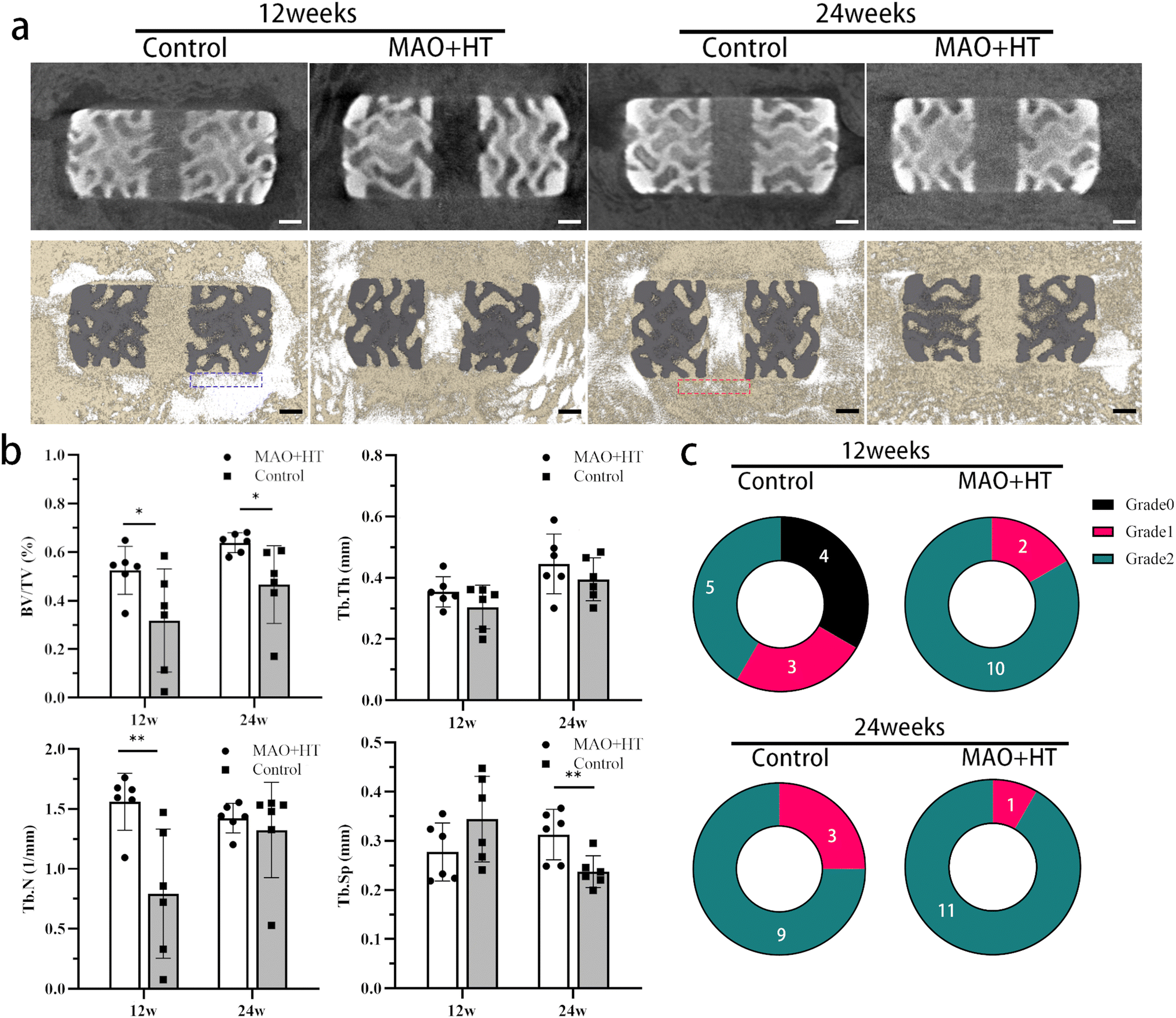 | ||
| Fig. 3 Imaging reconstruction and analysis: (a) representative 2D and 3D micro-CT images of cages and the upper and lower endplates at 12 and 24 weeks after surgery; (b) quantitative analyses of trabecular bone volume fraction (BV/TV), trabecular thickness (Tb.Th), trabecular number (Tb.N), and trabecular separation (Tb.Sp) for ROI described above; (c) classification and induction of intervertebral fusion status according to our criteria, the size bar represents 1 mm. | ||
 | ||
| Fig. 4 Representative fluorescence imaging at 12 and 24 weeks after surgery: (a) region of endplate–cage interface labelled by calcein green and xylenol orange (b) the measurement of mineral apposition rate, C represents cage, F represents fibrous tissue, NB represents new bone, arrows indicate bone growth direction. | ||
Representative histological images of methylene blue acid fuchsin and modified Goldner trichrome staining of different groups are shown in Fig. 5. For the MAO + HT surface, more extensive and homogeneously distributed newly generated bone could be detected and gradually penetrated intra-porous region from 12 to 24 weeks (red triangle in Fig. 5a), indicating a continuous ingrowth process. There was a direct contact between the MAO-HT cage implant and surrounding bone tissue. In contrast, bone trabeculae around the untreated cages were sparse, thin and exhibited ruptures. Moreover, fibrous tissue barrier between the untreated cage surface and native bone was commonly observed (white triangle in Fig. 5) just like fluorescence images, which showed an improvement at week 24.
 | ||
| Fig. 5 Histomorphology analysis of the new formed tissue within the fusion zone between endplate and cage at 12 and 24 weeks. (a) Representative images of Goldner trichrome staining of the hard-tissue slices, black regions correspond to the cages, green color represents mineralized bone, orange color represents osteoid, brown color represents fibrous tissue, (b) representative images of methylene blue acid fuchsin staining of the hard-tissue slices, red color represents bone tissue, blue color represents fibrous tissue. Red triangle: bone tissue penetrated into intra-porous region, white triangle: fibrous tissue barrier. | ||
 | ||
| Fig. 6 EDS elemental map and line scan of Ti, C, O Ca and P across the endplate–cage interface at 12 weeks: (a) MAO + HT group; (b) untreated group. | ||
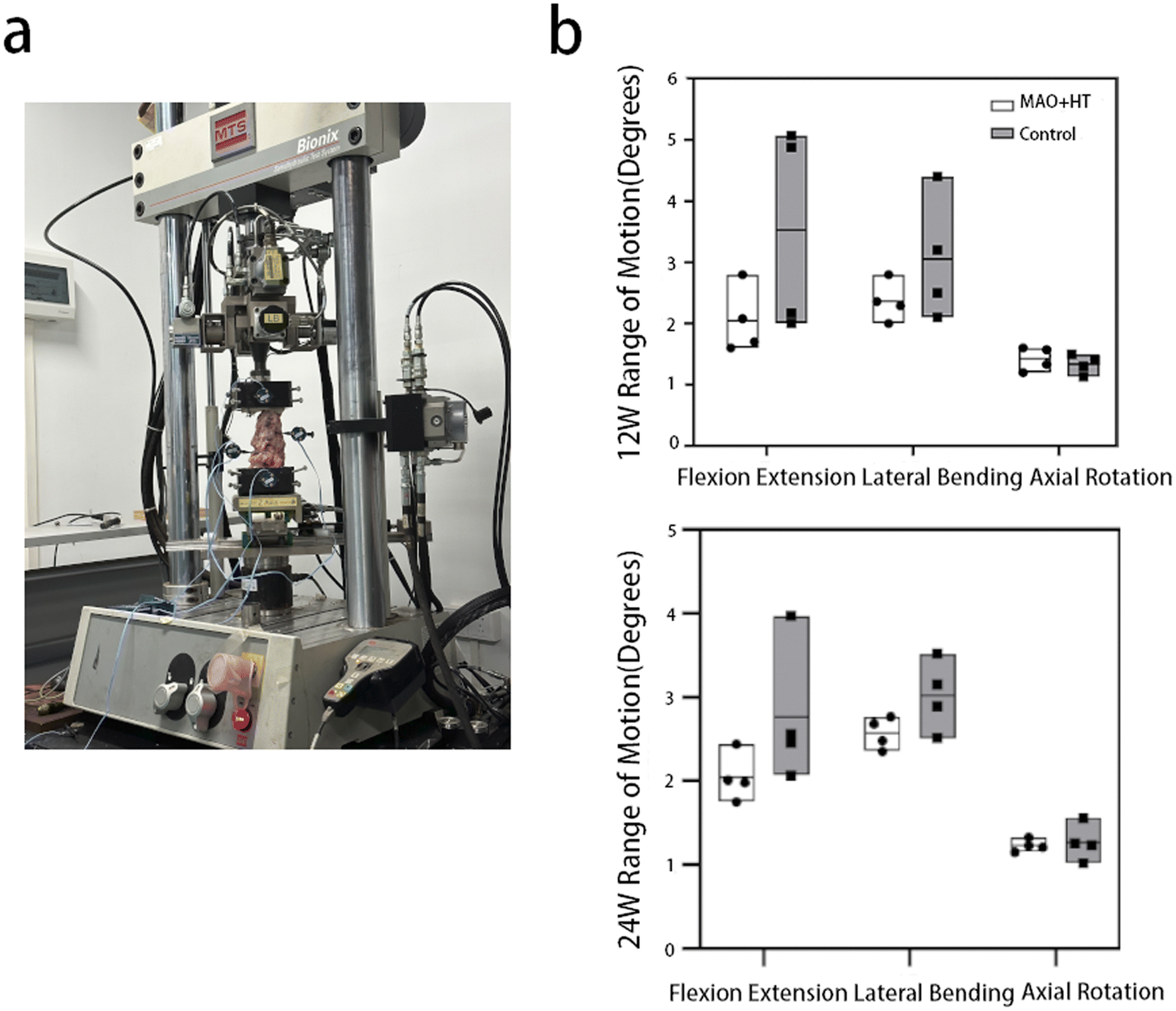 | ||
| Fig. 7 Biomechanical analysis: (a) spinal motion segments fixed with 3D movement measuring system via cement; (b) range of motion (ROM) data collected for each loading mode. | ||
4 Discussion
In the current study, a high Ca/P ratio coating with hierarchical surface topography, which is similar to that of bone apatite, was successfully prepared on 3D printed titanium substrate through MAO and subsequent HT. Through the sheep ACDF model, we confirmed that the 3D printed Ti cage treated with MAO-HT technology could effectively promote interbody fusion and improve the motion stability of the cervical segments. MAO treatment could lead to a micron-scale topographical surface with numerous hemispheric rosette-like clumps. The subsequent HT process enables the in situ nucleation and growth of nano petals on MAO-fabricated surface. Using NaOH solution to perform hydrothermal treatment on titanium alloys helps to induce the formation of hydroxyapatite, thereby enhancing the bioactivity of titanium implants.42 During the hydrothermal treatment, the following chemical reactions occur:43TiO2 oxide film reacts with OH− as follows:
| TiO2 + OH− → HTiO3− | (1) |
Titanium further reacts with OH−:
| Ti + 3OH− → Ti(OH)3+ + 4e− | (2) |
| Ti(OH)3+ + e− → TiO2·H2O + 1/2H2↑ | (3) |
| Ti(OH)3+ + OH− ↔ Ti(OH)4 | (4) |
Hydrated TiO2 will continue to react with OH−:
| TiO2·nH2O + OH− ↔ HTiO3−·nH2O | (5) |
As a result, negatively charged hydrates form on the substrate surface, which can attract sodium ions from the solution through electrostatic interactions to form a sodium titanate hydrogel layer. The sodium ions in the hydrogel layer exchange with H3O+ in the aqueous solution, leading to an increase in the pH value on the substrate surface. The increase in pH enhances the ionic activity of hydroxyapatite, promoting its nucleation.44 During the hydrothermal reaction, calcium ions and phosphate ions in the film layer diffuse outward under the influence of the hydrothermal medium, forming a locally supersaturated region of calcium and phosphate ions on the film surface. These calcium and phosphate ions react with hydroxide ions in the hydrothermal medium to produce hydroxyapatite. The reaction equation is as follows:
| 10Ca2+ + 6PO43− + 2OH− → Ca10(PO4)6(OH)2 | (6) |
During the bone remolding stage of the spine fusion, osteoclasts acidify the mineralized matrix, dissolving calcium phosphate crystals and creating microscale resorption lacunae (30–100 μm in diameter), and leave the collagen tufts and fibers as scaffolds at the submicro- and nanoscale.14 Similar characteristically complex topology of 3D printed titanium alloys treated with MAO-HT can be recognized by osteoblasts then facilitate subsequent osseointegration.45 Meanwhile, a robust interlock between the bone matrix and sub-micron topographical surface structures can be indicated by the non-collagenous proteins matrix secreted by the differentiating osteoblasts called “the cement line”.46
Since the surface is the only region in contact with host bone tissue initially, surface characteristics are widely implicated in regulating several biological events that determine the mechanical stability and osseointegration outcome of the implant.47 Meanwhile, microscopic morphology plays an important role in preventing a chronic immune response as well as regulating cell behaviors like attachment and differentiation. For example, Navarrete et al. found that NHOst and hMSCs cells seeded on surfaces with various topography characteristics displayed different integrin subunit expression, alkaline phosphatase activity and osteocalcin content,48 suggesting that osteoblast lineage cells are sensitive to specific micro/nanostructures. In the present study, an evenly distributed crater-like porous structure with various pore sizes in microscale along with significantly different unique nano hemispheric rosette-like “clumps” structures in nanoscale after MAO + HT treatment was proved to promote the adhesion and proliferation of hBMSCs in vitro (Fig. 2). Meanwhile, higher degree of osteogenic differentiation of hBMSCs seeded on MAO + HT surface is demonstrated by increased ALP activity which is high in mineralized tissue cells and is considered to be an early marker of osteogenic differentiation. Surface wettability also take part in the regulation of classically activated (M1) macrophages and anti-inflammatory (M2) to maintain the balance of wound clearance and regeneration in bone repair. Meanwhile, the increased surface wettability combined with suitable nanostructures leading to continuous protein adsorption and the formation of a blood clot and fibrin network on the implant surface,49 which is conducive to the adhesion and differentiation of osteogenesis-related cells.50 Through the water contact angle experiment, it is proved that hydrothermal treatment can further improve the hydrophilicity of titanium alloy surface after MAO, providing a more appropriate active interface for bone repair (ESI Table 1†).
Interbody cage and internal fixation system play a major role in limiting motion and load bearing in the early postoperative period. Over time, along with the bone absorption and remodeling, a fusion mass forms in intervertebral space and load is transmitted through the newly formed bone.12 The lack of interlock between interbody cages and host bone generates a vicious cycle that starts with micromotion and inflammation and ends with thickening of the fibrous layer, surrounding bone resorption and loosening of the cage.14 Anteroposterior migration of the cage may lead to progressive spinal deformity and narrowing of the disc space, even mechanical compression and secondary damage of spinal canal or foramen in some serious cases.51 While, subsidence of an interbody cage into the vertebral body can lead to loss of indirect decompression and recurrence of neural compression.
In this experiment, no significant interbody cage migration or subsidence was detected in both groups. However, the vicious cycle mentioned above was founded in untreated group which trigger deterioration of stability in flexion, lateral bending directions (Fig. 5 and 7).
As we know, the mechanical property of the connection between the implant and the bone is one of the important parameters to determine the stability of implant. The stiffness of bone–implant interface changes along with the process of new bone formation that originated from the implant surface (so called contact osteogenesis) and the other from the pre-existing host bone (so called distance osteogenesis).52,53 It has been demonstrated that contact osteogenesis is significantly faster than distance osteogenesis. More in detail, there is an open gap between the front of contact osteogenesis and distance osteogenesis during early stage of bone repair (days 0–30), resulting in low bone–implant interface stiffness constant around 1.87 GPa. It was not until the open gap closed (days 50) that the stiffness of the material begins to significantly increase, reaching 25 GPa, close to mature bone (days 100).52 Thanks to the favourable cytocompatibility and osteogenic properties (Fig. 2), we found both contact osteogenesis and distance osteogenesis within the bone–MAO + HT cages interface, while in the case of smooth cage surfaces only distance osteogenesis was observed (Fig. 4a). It is easy to infer that the open gap existed within bone–untreated cage interface will result in micromotions between the cage and endplate, leading to decreased bonding strength and increased risk of fusion failure. And the bone–MAO + HT cages interface achieves stable mechanical strength in a relatively short period of time due to early contact of the osteogenic front ends in both directions.
Variations in trabecular bone architecture have been known to reflect mechanical quality of interbody fusions during the fusion process. As reported by Theo et al., a more coarser and homogeneous bone structure was observed in “mature” spinal fusions characterized by increase in BV/TV ratio and Tb.Sp.54 In line with this theory, similar changes in parameters of trabecular bone from 12 to 24 weeks of MAO + HT group compared with the control indicate a high-quality fusion mass (Fig. 3b).
According to the EDS elemental map, a widely extended calcium- and phosphorus-rich layer was detected between the MAO + HT cages and bone, but not in untreated group (Fig. 6). Previous reports reveal that CaP on the surface may link bony tissue to the implants via chemical bonding thereby accelerating the process of bone–implant bonding, resulting in more rapid and firmer mechanically interlock.55 Furthermore, this thick calcium- and phosphorus-rich layer helps strengthen the vertebral endplate, which is particularly meaningful for osteoporotic patients. A single-center cohort study of 3D printed Ti cage subsidence for 55 patients showed that 8.2% of the vertebral bodies were found to have collapsed by more than 20% volume, and poor bone quality was considered as one of the most statistically significant risk factors.56 Similarly, Okano et al. reported that vertebral bodies with lower endplate volumetric bone mineral density were prone to severe subsidence.57 Thus, though not happened in sheep model, more mature and thicker mineralized bone surrounding the MAO + HT cages may reduce the risk of long-term cage subsidence in human.
The principal limitation of the study is that we only validated the performance of one type of MAO + HT treated 3D printed interbody cage with certain surface chemical composition and morphological characteristics in sheep ACDF model. Theoretically, a series of fusion cages with different morphological characteristics and chemical components should be developed by adjusting the electrolyte ratio, voltage and other reaction conditions for in vivo evaluation, so as to summarize the interaction between the repair tissue and the device surface characteristics, which might be different from the bone defect model and is specific to the biomechanics and osteogenic microenvironment of the intervertebral space mentioned above. This follow-up work is currently underway until the most suitable 3D printing interbody cage surface treatment completed by clinical validation.
5 Conclusion
In this study, a bioactive CaP coating with micro/nano multilevel morphology was developed on MAO + HT treated 3D printed Ti6Al4V. This coating helped to enhance the hydrophilicity, cell compatibility, and cell adhesion of hBMSCs on the material surface in vitro. Meanwhile, a tendency of higher expression of the osteogenic marker ALP suggested a possible early osteogenic commitment for MAO + HT group. In sheep ADCF model, compared with the untreated group, there were more direct contact and better fusion between the MAO + HT treated 3D interbody cage and surrounding bone tissue in the intervertebral space. Meanwhile, the better flexion–extension and lateral bending stability of the implanted segment at 12 weeks indirectly verified the promoting effect of the surface treated interbody cage on early fusion. The limitation of this study is the lack of a control group that only applies MAO or HT to identify the specific biological activity differences of each technology. However, despite the large differences between physiological and biomechanical environments, this study confirms that similar to the bone defect model, appropriate MAO + HT treatment can significantly promote bone repair in the interbody fusion. This discovery prompts us to develop more technologies and reaction parameters to find the optimal surface treatment scheme for clinical fusion devices.Abbreviations
| MAO | Microarc oxidation |
| HT | Hydrothermal treatment |
| CLSM | Confocal laser scanning microscope |
| ACDF | Anterior cervical discectomy and fusion |
| SEM | Scanning electron microscopy |
| XRD | X-ray diffraction |
| XPS | X-ray photoelectron spectroscopy |
| EDS | Energy dispersive spectrometer |
| ROI | Region of interest |
Ethical statement
All experimental designs and protocols involving animals were approved by the Animal Ethics Committee Peking University Institutional Review Board Office (LA2022558) and complied with the recommendations of the academy's animal research guidelines.Data availability
The data supporting this article have been included as part of the ESI.†Author contributions
Jiang Sun: investigation, data curation, writing – original draft. Shan-Shan Liu: investigation, data curation. Da Zou: writing – review & editing. Ren-Hua Ni: data curation. Cong-Bin Wei: resources. Hao Wang: resources. Wei-Shi Li: writing – review & editing.Conflicts of interest
The patent for the surface treatment technology used in the study was vested in Beijing AKec Medical Co., Ltd. The authors Chong-Bin Wei and Hao Wang work for the company. No financial support for the study was provided by the company. No other author has reported a potential conflict of interest relevant to this article.Acknowledgements
This work was supported by the Research and Application of Clinical Diagnosis and Treatment Technology Foundation of Beijing (Grant No. Z201100005520073).References
- S. Jain, A. E. Eltorai, R. Ruttiman and A. H. Daniels, Orthop. Surg., 2016, 8, 278–284 CrossRef.
- C. D. Lopez, V. Boddapati, J. M. Lombardi, N. J. Lee, C. Saifi, M. D. Dyrszka, Z. M. Sardar, L. G. Lenke and R. A. Lehman, Spine J., 2020, 20, 1586–1594 CrossRef PubMed.
- C. Q. Jia, Z. Zhang, S. Q. Cao, T. J. Wang, H. C. Yu, W. X. Wang, B. M. Guo, X. Y. Qiu, Y. G. You, F. Q. Hu, J. Zhao and X. S. Zhang, Bioact. Mater., 2023, 23, 234–246 CAS.
- G. W. Bagby, Orthopedics, 1988, 11, 931–934 CrossRef CAS.
- J. R. Dimar, S. D. Glassman, K. J. Burkus and L. Y. Carreon, Spine, 2006, 31, 2534–2539 CrossRef PubMed ; discussion 2540..
- M. R. Van Horn, R. Beard, W. Wang, B. W. Cunningham, K. P. Mullinix, M. Allall and B. S. Bucklen, Spine J., 2021, 21, 2097–2103 CrossRef PubMed.
- G. Fogel, N. Martin, K. Lynch, M. H. Pelletier, D. Wills, T. Wang, W. R. Walsh, G. M. Williams, J. Malik, Y. Peng and M. Jekir, Spine J., 2022, 22, 1028–1037 CrossRef.
- P. Li, W. Jiang, J. Yan, K. Hu, Z. Han, B. Wang, Y. Zhao, G. Cui, Z. Wang, K. Mao, Y. Wang and F. Cui, J. Biomed. Mater. Res., Part A, 2019, 107, 1386–1392 CrossRef CAS.
- K. C. McGilvray, J. Easley, H. B. Seim, D. Regan, S. H. Berven, W. K. Hsu, T. E. Mroz and C. M. Puttlitz, Spine J., 2018, 18, 1250–1260 CrossRef PubMed.
- T. Makino, S. Takenaka, Y. Sakai, H. Yoshikawa and T. Kaito, Global Spine J., 2022, 12, 931–939 CrossRef.
- P. M. Beck, Oral Health, 1970, 60, 19–21 CAS passim..
- P. J. Rao, M. H. Pelletier, W. R. Walsh and R. J. Mobbs, Orthop. Surg., 2014, 6, 81–89 CrossRef PubMed.
- W. Liu, X. Li, Y. Jiao, C. Wu, S. Guo, X. Xiao, X. Wei, J. Wu, P. Gao, N. Wang, Y. Lu, Z. Tang, Q. Zhao, J. Zhang, Y. Tang, L. Shi and Z. Guo, ACS Appl. Mater. Interfaces, 2020, 12, 51885–51903 CrossRef CAS PubMed.
- R. A. Gittens, R. Olivares-Navarrete, Z. Schwartz and B. D. Boyan, Acta Biomater., 2014, 10, 3363–3371 CrossRef PubMed.
- T. Zhang, W. Zhou, Z. Jia, Q. Wei, D. Fan, J. Yan, C. Yin, Y. Cheng, H. Cai, X. Liu, H. Zhou, X. Yang, Y. Zheng and Z. Liu, Sci. China Mater., 2018, 61, 579–592 CrossRef CAS.
- S. Amin Yavari, J. van der Stok, Y. C. Chai, R. Wauthle, Z. Tahmasebi Birgani, P. Habibovic, M. Mulier, J. Schrooten, H. Weinans and A. A. Zadpoor, Biomaterials, 2014, 35, 6172–6181 CrossRef CAS PubMed.
- H. Lee, T.-S. Jang, J. Song, H.-E. Kim and H.-D. Jung, Mater. Lett., 2016, 185, 21–24 CrossRef CAS.
- M. A. Lopez-Heredia, J. Sohier, C. Gaillard, S. Quillard, M. Dorget and P. Layrolle, Biomaterials, 2008, 29, 2608–2615 CrossRef CAS.
- P. Xiu, Z. Jia, J. Lv, C. Yin, Y. Cheng, K. Zhang, C. Song, H. Leng, Y. Zheng, H. Cai and Z. Liu, ACS Appl. Mater. Interfaces, 2016, 8, 17964–17975 CrossRef CAS PubMed.
- J. C. M. Souza, M. B. Sordi, M. Kanazawa, S. Ravindran, B. Henriques, F. S. Silva, C. Aparicio and L. F. Cooper, Acta Biomater., 2019, 94, 112–131 CrossRef CAS.
- S. Sikdar, P. V. Menezes, R. Maccione, T. Jacob and P. L. Menezes, Nanomaterials, 2021, 11, 1375 CrossRef CAS PubMed.
- Q. Du, D. Q. Wei, S. D. Wang, S. Cheng, Y. M. Wang, B. Q. Li, D. C. Jia and Y. Zhou, Appl. Surf. Sci., 2019, 487, 708–718 CrossRef CAS.
- Y. Han, J. H. Zhou, S. M. Lu and L. Zhang, RSC Adv., 2013, 3, 11169–11184 RSC.
- H.-J. Song, J.-W. Kim, M.-S. Kook, W.-J. Moon and Y.-J. Park, Appl. Surf. Sci., 2010, 256, 7056–7061 CrossRef CAS.
- Y. Li, W. Wang, F. Yu, D. Wang, S. Guan, Y. Li and M. Qi, Mater. Sci. Eng., C, 2020, 109, 110610 CrossRef CAS PubMed.
- H.-J. Song, K.-H. Shin, M.-S. Kook, H.-K. Oh and Y.-J. Park, Surf. Coat. Technol., 2010, 204, 2273–2278 CrossRef CAS.
- G. Li, H. Cao, W. Zhang, X. Ding, G. Yang, Y. Qiao, X. Liu and X. Jiang, ACS Appl. Mater. Interfaces, 2016, 8, 3840–3852 CrossRef CAS PubMed.
- G. L. Zhao, L. Xia, B. Zhong, S. S. Wu, L. Song and G. W. Wen, Trans. Nonferrous Met. Soc. China, 2015, 25, 1151–1157 CrossRef CAS.
- P. L. Jiang, J. H. Liang and C. J. Lin, Appl. Surf. Sci., 2013, 280, 373–380 CrossRef CAS.
- W. Shang, B. Chen, X. Shi and Y. Wen, Chin. J. Mater. Res., 2011, 25, 57–60 CAS.
- P. Shi, W. F. Ng, M. H. Wong and F. T. Cheng, J. Alloys Compd., 2009, 469, 286–292 CrossRef CAS.
- W. Zhang, G. Wang, Y. Liu, X. Zhao, D. Zou, C. Zhu, Y. Jin, Q. Huang, J. Sun, X. Liu, X. Jiang and H. Zreiqat, Biomaterials, 2013, 34, 3184–3195 CrossRef CAS PubMed.
- X. Shen, Y. Zhang, P. Ma, L. Sutrisno, Z. Luo, Y. Hu, Y. Yu, B. Tao, C. Li and K. Cai, Biomaterials, 2019, 212, 1–16 CrossRef CAS PubMed.
- Y. Zhao, H. Cao, H. Qin, T. Cheng, S. Qian, M. Cheng, X. Peng, J. Wang, Y. Zhang, G. Jin, X. Zhang, X. Liu and P. K. Chu, ACS Appl. Mater. Interfaces, 2015, 7, 17826–17836 CrossRef CAS.
- I. A. J. van Hengel, M. Lacin, M. Minneboo, L. E. Fratila-Apachitei, I. Apachitei and A. A. Zadpoor, Mater. Sci. Eng., C, 2021, 124, 112074 CrossRef CAS PubMed.
- Q. Huang, X. Liu, T. A. Elkhooly, R. Zhang, Z. Shen and Q. Feng, Colloids Surf., B, 2015, 134, 169–177 CrossRef CAS PubMed.
- N. Newell, J. P. Little, A. Christou, M. A. Adams, C. J. Adam and S. D. Masouros, J. Mech. Behav. Biomed. Mater., 2017, 69, 420–434 CrossRef CAS.
- H. Xu, F. Zhang, H. Wang, F. Geng, M. Shao, S. Xu, X. Xia, X. Ma, F. Lu and J. Jiang, BioMed Res. Int., 2018, 2018, 7961509 Search PubMed.
- Y. Hojo, Y. Kotani, M. Ito, K. Abumi, T. Kadosawa, Y. Shikinami and A. Minami, Biomaterials, 2005, 26, 2643–2651 CrossRef CAS PubMed.
- T. Zhang, Q. Wei, D. Fan, X. Liu, W. Li, C. Song, Y. Tian, H. Cai, Y. Zheng and Z. Liu, Biomater. Sci., 2020, 8, 1279–1289 RSC.
- S. Wang, H. Leng, Y. Tian, N. Xu and Z. Liu, BMC Musculoskeletal Disord., 2021, 22, 121 CrossRef CAS.
- L. Huang, B. Cai, Y. Huang, J. Wang, C. Zhu, K. Shi, Y. Song, G. Feng, L. Liu and L. Zhang, ACS Omega, 2021, 6, 1465–1476 CrossRef CAS PubMed.
- H. M. Kim, F. Miyaji, T. Kokubo and T. Nakamura, J. Biomed. Mater. Res., 1996, 32, 409–417 CrossRef CAS.
- T. Kokubo, H. M. Kim and M. Kawashita, Biomaterials, 2003, 24, 2161–2175 CrossRef CAS PubMed.
- R. J. McMurray, N. Gadegaard, P. M. Tsimbouri, K. V. Burgess, L. E. McNamara, R. Tare, K. Murawski, E. Kingham, R. O. C. Oreffo and M. J. Dalby, Nat. Mater., 2011, 10, 637–644 CrossRef CAS.
- J. E. Davies, E. Ajami, R. Moineddin and V. C. Mendes, Biomaterials, 2013, 34, 3535–3546 CrossRef CAS.
- R. Agarwal and A. J. Garcia, Adv. Drug Delivery Rev., 2015, 94, 53–62 CrossRef CAS.
- R. Olivares-Navarrete, S. L. Hyzy, M. E. Berg, J. M. Schneider, K. Hotchkiss, Z. Schwartz and B. D. Boyan, Ann. Biomed. Eng., 2014, 42, 2551–2561 CrossRef.
- B. S. Kopf, S. Ruch, S. Berner, N. D. Spencer and K. Maniura-Weber, J. Biomed. Mater. Res., Part A, 2015, 103, 2661–2672 CrossRef CAS PubMed.
- K. M. Hotchkiss, G. B. Reddy, S. L. Hyzy, Z. Schwartz, B. D. Boyan and R. Olivares-Navarrete, Acta Biomater., 2016, 31, 425–434 CrossRef CAS.
- M. K. Park, K. T. Kim, W. S. Bang, D. C. Cho, J. K. Sung, Y. S. Lee, C. K. Lee, C. H. Kim, B. K. Kwon, W. K. Lee and I. Han, Spine J., 2019, 19, 437–447 CrossRef.
- S. Gershov, J. Xie, F. A. Shah, K. Shemtov-Yona and D. Rittel, Acta Biomater., 2022, 154, 302–311 CrossRef CAS PubMed.
- N. Amor, L. Geris, J. Vander Sloten and H. Van Oosterwyck, Acta Biomater., 2011, 7, 779–790 CrossRef CAS PubMed.
- T. H. Smit, R. Müller, M. van Dijk and P. I. Wuisman, Spine, 2003, 28, 1802–1808 CrossRef PubMed ; discussion 1809..
- Z. M. Huang, Y. Y. Qi, S. H. Du, G. Feng, H. Unuma and W. Q. Yan, Sci. Technol. Adv. Mater., 2013, 14, 055001 CrossRef CAS.
- H. Wu, Z. Shan, F. Zhao and J. P. Y. Cheung, Clin. Orthop. Relat. Res., 2022, 480, 163–188 CrossRef.
- I. Okano, C. Jones, S. N. Salzmann, M. J. Reisener, O. C. Sax, C. Rentenberger, J. Shue, J. A. Carrino, A. A. Sama, F. P. Cammisa, F. P. Girardi and A. P. Hughes, Eur. Spine J., 2020, 29, 1131–1140 CrossRef.
Footnotes |
| † Electronic supplementary information (ESI) available. See DOI: https://doi.org/10.1039/d3ra08185k |
| ‡ Jiang Sun and Shan-Shan Liu contribute equally to this manuscript and are considered as co-first authors. |
| This journal is © The Royal Society of Chemistry 2024 |