
 Open Access Article
 This Open Access Article is licensed under a Creative Commons Attribution-Non Commercial 3.0 Unported Licence
Functionalisation of alkali-resistant nanoporous glass via Au nanoparticle decoration using alkaline impregnation: catalytic activity for CO removal
Kohei Tada a,
Masato Tsujiguchi*b,
Takumi Tominagab,
Masaru Iwaoc,
Hiroaki Sakuraid,
Tetsuro Jind and
Yasushi Maeda*a
a,
Masato Tsujiguchi*b,
Takumi Tominagab,
Masaru Iwaoc,
Hiroaki Sakuraid,
Tetsuro Jind and
Yasushi Maeda*a
aResearch Institute of Electrochemical Energy (RIECEN), National Institute of Advanced Industrial Science and Technology (AIST), 1-8-31 Midorigaoka, Ikeda, Osaka 563-8577, Japan. E-mail: y-maeda@aist.go.jp
bDevelopment Division, Research and Development Group, Nippon Electric Glass Co., Ltd., 7-1, Seiran 2-chome, Otsu, Shiga 520-8639, Japan. E-mail: mtsujiguchi@neg.co.jp
cQuality Assurance Department, Electronic Products Division, Nippon Electric Glass Co., Ltd., 906, Ima-cho, Higashi-ohmi, Shiga 521-1295, Japan
dNanomaterials Research Institute (NMRI), National Institute of Advanced Industrial Science and Technology (AIST), 1-8-31 Midorigaoka, Ikeda, Osaka 563-8577, Japan
First published on 11th March 2024
Abstract
The concerted use of nano-metal particles with catalytic functions and nanoporous materials holds promise for effective air purification and gas sensing; however, only a few studies have used porous glasses as supports for Au nanoparticles. Furthermore, Au/nanoporous glasses with activities comparable to that of Au/TiO2, which is a typical Au catalyst, have not been reported to date. This study demonstrates that a nanoporous glass, which is highly acid- and alkali-resistant and chemically stable, can be decorated with Au nanoparticles using an alkali impregnation method. The resulting composite exhibits high catalytic activity in CO oxidation. The catalysts reported herein are as active as Au/TiO2 catalysts per active site. Further optimisation of the pore properties of the glass and sizes of the Au nanoparticles is expected to result in excellent catalytic systems for CO removal and sensing.
1. Introduction
The removal of toxic gases is critical to preserving the global environment. To this end, the use of nanoporous materials is effective because they have large surface areas and effectively adsorb gases. In addition, gas selectivity can be realised by adjusting the material porosity. The catalytic decomposition of toxic gases offers another effective approach. For example, Rh, Pd, and Pt nanoparticles have been used as catalysts in removing NOx, CO, and hydrocarbons from vehicle exhaust gases. Hence, the concerted use of nanoporous materials and nano-metal particles with catalytic functions holds great promise for effective air purification and gas sensing.1–13Supported Au nanoparticles on oxides exhibit various catalytic activities.14–17 Extensive research efforts have highlighted the crucial role of the heterojunction between the oxide support and Au nanoparticles in catalytic functions.16–20 CO oxidation is a representative reaction of Au catalysts, and CO is a typical toxic gas that must be removed for air purification. Therefore, the dependence of the CO oxidation activities of Au catalysts on supporting oxides has been well studied. Au/TiO2 and Au/Fe2O3 are active even below 0 °C,14,21 whereas the catalytic activity of Au/SiO2 is generally low.11,16,22–24 Furthermore, different approaches compared to those used for TiO2 and Fe2O3 are required to decorate SiO2 with Au nanoparticles.9–11,22–24 The difficulty of depositing Au nanoparticles onto SiO2 and the low catalytic activity of Au/SiO2 hinder the application of meso/nanoporous SiO2-based materials as supports for Au nanoparticles.
To address these issues, methods for supporting Au nanoparticles onto mesoporous SiO2 have been investigated,6–12 and the catalytic activities of Au/mesoporous SiO2 have been reviewed.10,11 Yan et al. recently attempted to fabricate a composite of Au nanoparticles with mesoporous silica via a catalytic reaction.9 They used nitrophenol reduction by the Au/SiO2 system as the catalytic reaction. Nitrophenol reduction is a typical catalytic reaction of Au/oxide systems in the liquid phase, and the catalytic activity of Au/SiO2 system is high. Furthermore, mesoporous-SiO2-based Au catalysts exhibit unique activities such as propylene epoxidation. Therefore, the application of mesoporous-SiO2-based materials to catalytic systems is interesting. However, to the best of our knowledge, CO oxidation activities comparable to that of Au/TiO2 or Au/Fe2O3 have not been reported using Au/nanoporous glass systems. This low activity in CO oxidation remains a challenge for the application of meso/nanoporous glasses in air purification.
Achieving comparable activity to Au/TiO2 for CO oxidation using Au/nanoporous glass composites would represent a novel approach for air purification. Herein, this paper reports that composites of SiO2–ZrO2 nanoporous glass (SZ-NPG), a recently reported material,13,25 decorated with Au nanoparticles, exhibit activity comparable to that of Au/TiO2 in CO oxidation. The catalytic activity of Au/SZ-NPG is compared with those of Au/SiO2, Au/ZrO2, and Au/TiO2, and the reasons for the higher activity compared to that of the Au/SiO2 system are discussed.
2. Experimental
2.1. Materials
2.2. Instrumentals
S-5500 (Hitachi, Tokyo, Japan) was used for scanning electron microscopy (SEM) to estimate the size distribution of Au nanoparticles. Secondary and high-angle backscattered electrons were measured with an acceleration voltage of 30 kV.The pore structure was characterised using the nitrogen adsorption desorption method with a surface area and pore size analyser (QUADRASORB SI, Anton Paar, Graz, Austria). The specific surface area was determined from the obtained adsorption isotherm using Brunauer–Emmett–Teller (BET) theory.
A fixed-bed flow reactor system was used to measure the CO oxidation activities. The temperature, which was controlled in a thermostatic chamber, was monitored using a Pt thermometer. The CO concentration in the reaction gas was analysed using gas chromatography (GC-8A, Shimadzu, Kyoto, Japan).
2.3. Catalytic tests
The catalytic plate or powder (100 mg) was packed into a sample tube and covered with silica wool. The packed sample was pre-treated with 20% O2 (Ar balance) for 20 min at 250 °C. CO gas (1%) in air, which was used as the reaction gas, was supplied at a flow rate of 33 mL min−1. The measurement temperature range was 0–200 °C. The conversion ratio was calculated based on the initial CO concentration.3. Results and discussion
3.1. Synthesis and characterisation of Au/SZ-NPG materials
Fig. 1(a) shows images of Au-free and Au-supported SZ-NPG. The glass plates are colourless and transparent before decoration with Au, whereas after Au addition, they exhibit red-to-purple colours, which darken with increasing Au loading. The colour is due to the plasmon absorption of the Au nanoparticles (528 nm), as shown in Fig. 1(b), which is determined by comparing the absorption wavelength with that of a colloid of Au nanoparticles. Fig. 2(a) and (b) show a typical SEM image and the size distribution of the supported Au nanoparticles of the sample used in entry 4 (1.0 wt% Au/SZ-NPG). Au nanoparticles with diameters in the range of 2–13 nm are supported within and outside the pores of SZ-NPG. The specific surface areas and pore properties of entries 1 and 4 are listed in Table 1. Under all conditions, the specific surface areas decreased significantly after loading Au nanoparticles. Highly dispersed silica nanoparticles is precipitated on the inner wall in the porous glass.31 It is assumed that the silica nanoparticles dissolved during Au loading, a process that uses an alkaline aqueous solution, causing a decrease in the specific surface area. It would be necessary to prevent such surface area reduction when utilising the gas adsorption properties of SZ-NPGs. However, as discussed below, the active site of Au/SZ-NPG catalysts for CO oxidation is the perimeter interface between nanoparticles and supports; therefore, the surface area of SZ-NPG does not significantly affect the catalytic activity. Conversely, the pore size distribution and volume are not affected. Hence, the pore properties of nanoporous glass are not altered by the AIM method. In addition, the actual loading of Au in entry 4 is 0.89 wt%, as determined via ICP-AES, suggesting that Au nanoparticle supporting is achieved using the AIM method.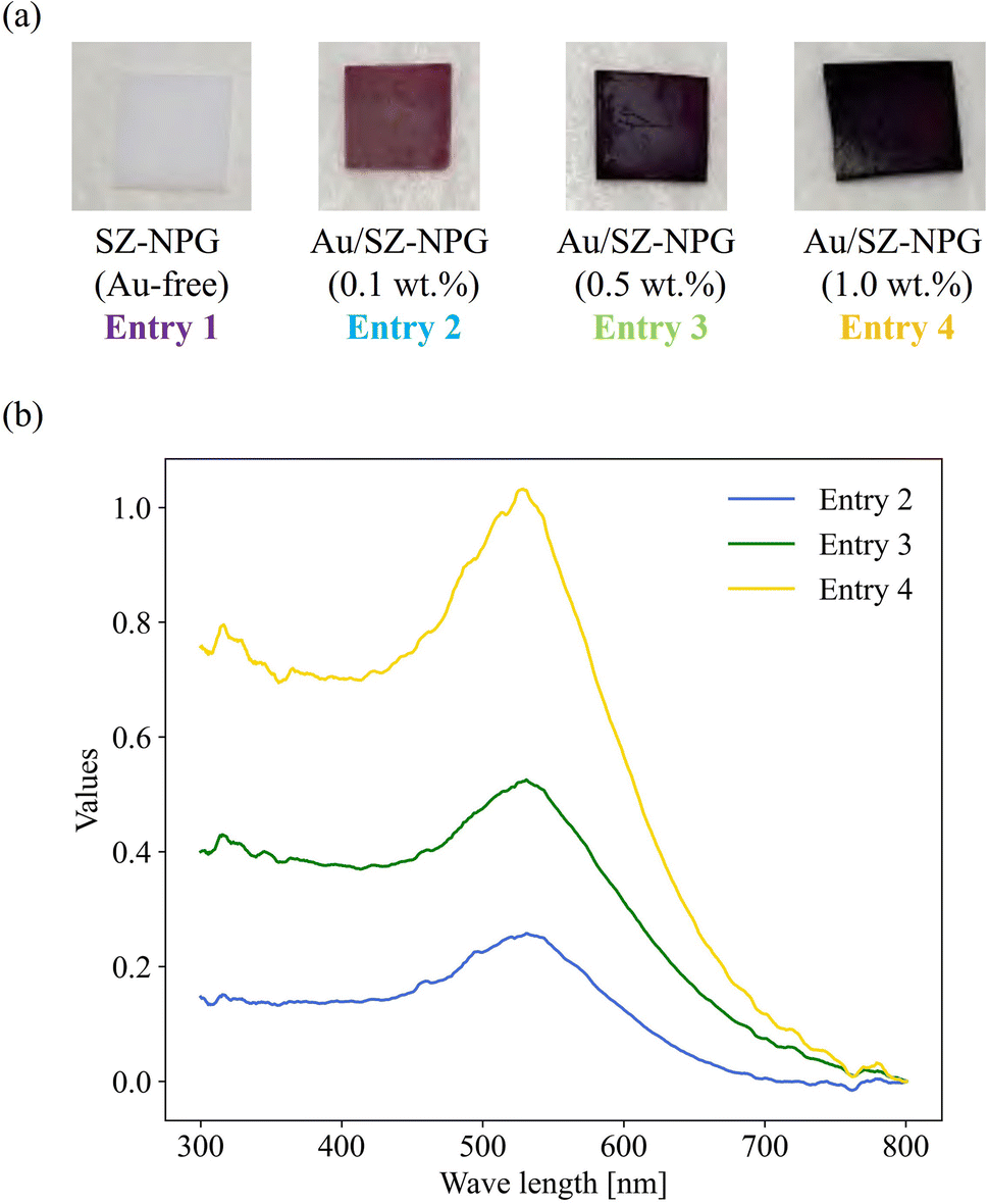 | ||
| Fig. 1 (a) Images of the prepared Au/SZ-NPG samples (entries 1–4). (b) Relative diffuse reflectance spectra of Au/SZ-NPG samples (entries 2–4). | ||
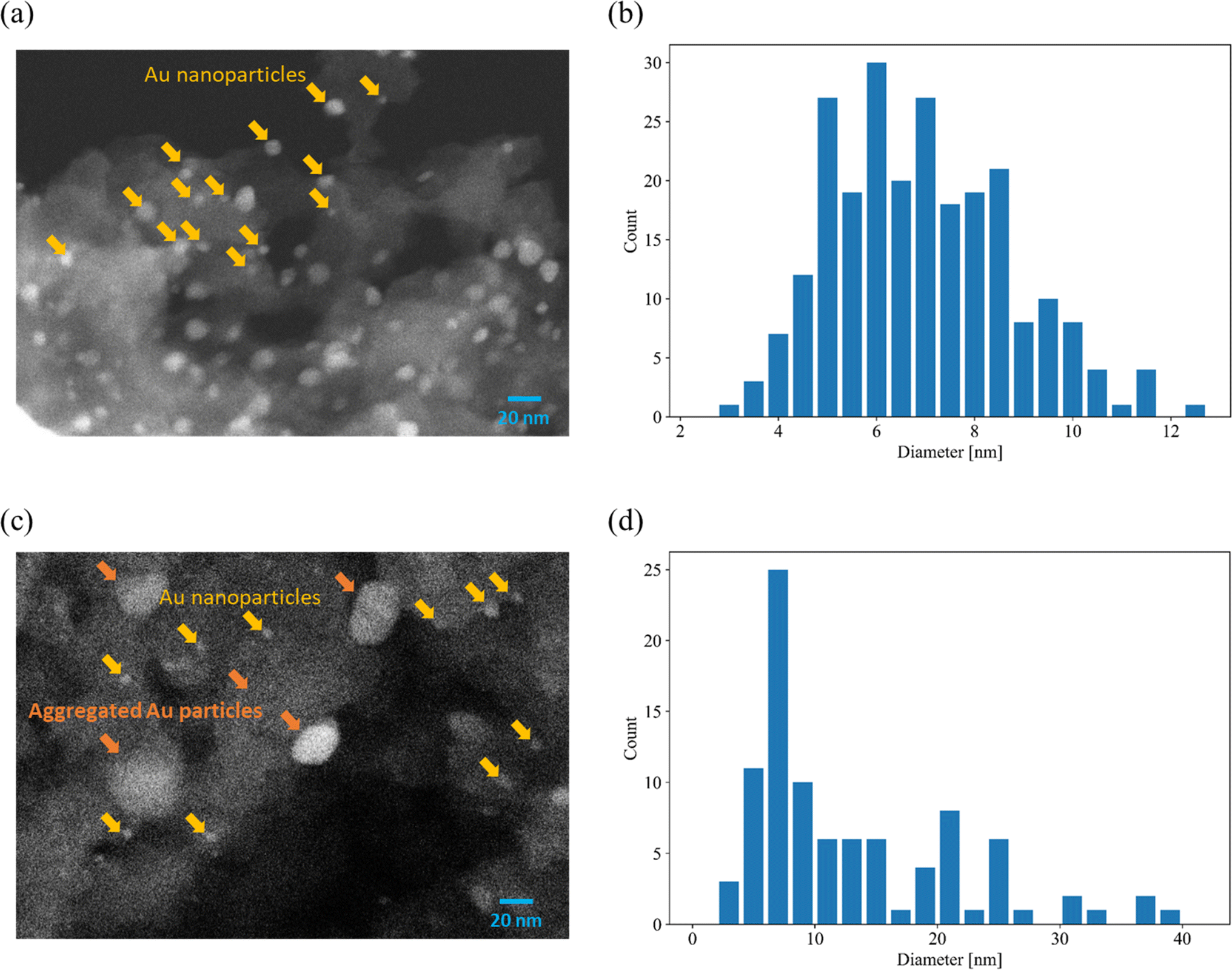 | ||
| Fig. 2 Typical SEM images and distributions of Au particle diameters. (a and b) 1.0 wt% Au/SZ-NPG (entry 4) and (c and d) 3.0 wt% Au/SZ-NPG (entry 5). | ||
| Entry | Specific surface area [m2 g−1] | Median of pore diameter [nm] | Pore volume [mL g−1] |
|---|---|---|---|
| 1 | 99 | 37 | 0.63 |
| 4 | 54 | 39 | 0.57 |
The over-agglomeration of Au particles occurred at a high Au loading. Fig. 2(c) shows a typical SEM image for 3.0 wt% Au/SZ-NPG (entry 5), and Fig. 2(d) shows the distribution map of the Au particle diameter estimated via SEM. The SEM image of the sample used in entry 4 displays numerous fine nanoparticles (≤10 nm) (Fig. 2(a)). Conversely, the SEM image of the sample used in entry 5 shows that the number of small particles (≤10 nm) is considerably reduced, and coarse particles with diameters of ∼20 nm are observed (Fig. 2(c)). The average size of the Au nanoparticles of the sample used in entry 5 is 14.1 nm (Fig. 2(d)), which is almost double that of the sample used in entry 4 (7.3 nm, Fig. 2(b)). The active sites of CO oxidation over Au catalysts occur at the perimeter of the Au nanoparticles,18–20 and the aggregation of Au is a crucial factor causing a decrease in the number of active sites.11,32–35 Hence, 3.0 wt% corresponds to over-loading, as it results in the formation of coarse Au particles that cannot effectively enhance the catalytic activity.
Next, we discuss why Au nanoparticles could be loaded onto SZ-NPG using the AIM method. Au is more prone to aggregation than other precious metals.11,16,35–38 The primary factor contributing to Au aggregation is the presence of Cl− within the Au precursors.32–35 Therefore, Cl− removal is crucial in preparing Au-nanoparticle-supported catalysts,11,16,35–39 achieved through processes such as neutralisation during the DP method21 and co-precipitation method.14 However, these methods are not applicable to acidic oxides, such as SiO2, because the isoelectric point of the support surface must be basic.11,36 Chloride-free Au precursors are effective in decorating acidic oxides with Au.10,22,27,28,30,38 Gold acetate is employed as a precursor for the AIM method. Due to the low solubility of gold acetate in water and its weak interaction with oxides, the acetate ions undergo ligand exchange to hydroxide ions when preparing the AIM method.27 In the DP method, the aqueous solution containing gold hydroxide contains chloride ions, requiring filtration. By contrast, the aqueous solution containing gold hydroxide prepared using the AIM method does not contain chloride ions, allowing for the effective deposition of [Au(OH)4]− onto the oxide by evaporation. The mechanism whereby gold precursors decompose to form fine particles has been investigated both experimentally and computationally.34,37,39–42 Although the mechanism has not been fully elucidated, Au nanoparticles can be obtained by calcining [Au(OH)4]− at 300–400 °C.27,28,37 The AIM method involves impregnation with a basic solution containing Na[Au(OH)4], which may alter the pore properties of acidic materials such as nanoporous glass. However, the pore properties remain unchanged, as demonstrated in Table 1. This is attributed to the high alkali resistance of SZ-NPG.13,25 Hence, the utilisation of alkali-resistant glass materials and effective adsorption of [Au(OH)4]− by impregnation in a chloride-free basic aqueous solution resulted in the successful support of Au nanoparticles.
3.2. Catalytic properties
Fig. 3 shows the dependence of the CO oxidation activity of Au/SZ-NPG on the Au loading (0–1.0 wt%). Bare SZ-NPG (entry 1) exhibits no CO oxidation activity over the measured temperature range. Even at a small loading of 0.1 wt% (entry 2), the effects of the Au nanoparticles are observed: a CO conversion of 5% is observed at room temperature (25 °C). The CO oxidation activity increases with increasing Au loading, and the sample used in entry 4 (1.0 wt% Au/SZ-NPG) exhibits activity even at 0 °C (conversion: 11%), with the CO conversion reaching 100% at 50 °C. The temperature at which the CO conversion is 50% (T1/2) is typically used to characterise the CO oxidation activity,11,16 and the T1/2 values of entries 1 (bare SZ-NPG), 2 (0.1 wt% Au/SZ-NPG), 3 (0.5 wt% Au/SZ-NPG), and 4 (1.0 wt% Au/SZ-NPG) are >200, 167, 74, and 26 °C, respectively. On the other hand, the CO conversion curve of entry 5 confirms that no increase in activity is observed compared to that of entry 4 (Fig. 4). The T1/2 value of entry 5 is 28 °C, which is similar to that of entry 4 (26 °C). In addition, the reaction rates per active site were estimated. No significant differences between entries 4 and 5 are observed (Table 2). The same activities of the samples with Au loadings of 1.0 and 3.0 wt% are ascribed to the aggregation of the Au nanoparticles (Fig. 2). The T1/2 value of CO conversion does not improve with an increase in the Au loading to >1 wt% due to the aggregation, and other techniques are required to improve the catalytic activity of Au/SZ-NPG. Hence, the catalytic activity of SZ-NPG is enhanced via the addition of Au nanoparticles, unless the over-aggregation of Au particles does not occur.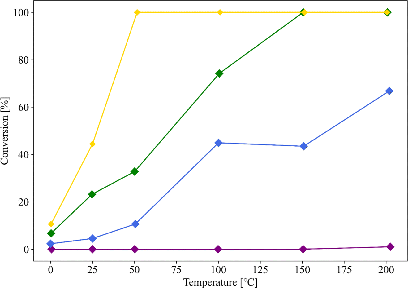 | ||
| Fig. 3 CO conversion curves of Au-free SZ-NPG (entry 1, purple), 0.1 wt% Au/SZ-NPG (entry 2, blue), 0.5 wt% Au/SZ-NPG (entry 3, green), and 1.0 wt% Au/SZ-NPG (entry 4, yellow). | ||
 | ||
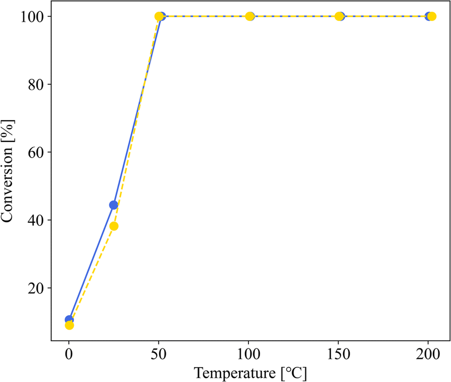
| Fig. 4 CO conversion curves of 1.0 wt% Au/SZ-NPG (entry 4, yellow dot line) and 3.0 wt% Au/SZ-NPG (entry 5, blue solid line). | ||
| Entry | Support | Loadinga [wt%] | Average diameter [nm] | T1/2 [°C] | TOFb [mol s−1 nm−1] |
|---|---|---|---|---|---|
| a Actual loading detected via ICP-AES, and the values in parenthesis are estimated based on the quantity of the Au precursor used.b Reaction rate per nanometre of Au perimeter (active site of CO oxidation) at 25 °C. The values in parenthesis are calculated using the Au loading estimated from the quantity of the Au precursor.c The samples were used for creating Fig. 2 in our prior study,22 although the specific values for the Au loading, diameter, and TOF were not reported in that study.d The sample is the same as sample 2 reported in a previous study.29 | |||||
| 4 | SZ-NPG | 0.89 (1.0) | 7.3 | 26 | 9.54 × 10⁻²⁴ |
| 5 | SZ-NPG | (3.0) | 14.1 | 28 | (1.06 × 10⁻²³) |
| 6 | TiO2 | (1.0) | 6.1 | 10 | (9.51 × 10⁻²⁴) |
| 7c | ZrO2 | 0.84 | 9.1 | 117 | 5.24 × 10⁻²⁵ |
| 8c | SiO2 | 0.75 | 7.7 | >200 | 1.13 × 10⁻²⁵ |
| 9d | TiO2 | 0.15 | 3.0 | 29 | 1.06 × 10⁻²³ |
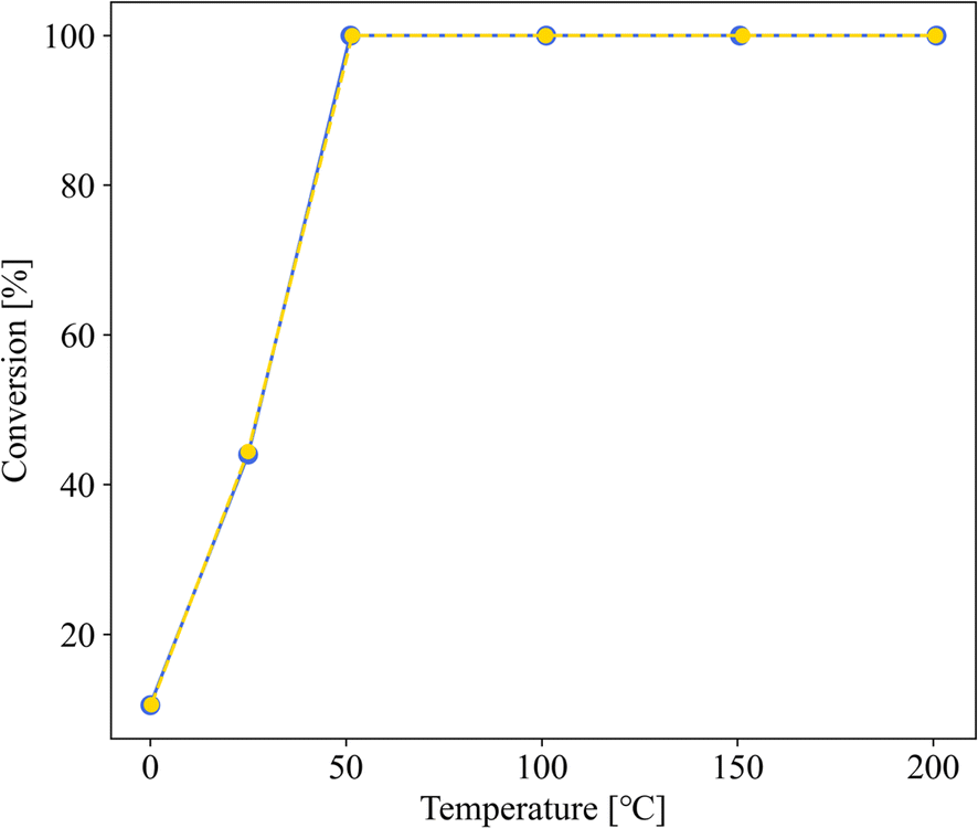
Before comparing the activity of Au/SZ-NPG with those of other gold catalysts, we investigated whether the shape of Au/SZ-NPG affects the activity measurement results. SZ-NPG is a plate and can be decorated by Au nanoparticles while maintaining its plate shape using the AIM method (Fig. 1(a)). Therefore, CO oxidation activities were measured on plate-shaped samples. Conversely, the catalyst support oxides used for comparison (TiO2, ZrO2, and SiO2) are in powder form, and CO oxidation reaction activity is typically measured using powder samples. Thereafter, the sample (entry 4: 1.0 wt% Au/SZ-NPG) whose activity was measured was removed from the reaction tube and ground using an agate mortar and pestle. The ground sample then sealed in the reaction tube, and its CO oxidation activity was re-measured. Fig. 5 illustrates that the CO oxidation activity remains consistent before and after grinding, indicating that the shape of SZ-NPG does not affect the accuracy of activity measurements, allowing for a comparison of the catalytic activity of Au/SZ-NPG with those of other gold catalysts.
 | ||
| Fig. 5 CO oxidation curves for entry 4 before (blue) and after (yellow) grinding. | ||
Au/SZ-NPG (entry 4), Au/TiO2 (entry 6), Au/ZrO2 (entry 7), and Au/SiO2 (entry 8) with Au loadings in the range of 0.8–1.0 wt% were then prepared, and their CO conversion curves were compared (Fig. 6). Au/SiO2 and Au/ZrO2, which are the main components of SZ-NPG, demonstrate lower CO oxidation activities than that of Au/SZ-NPG. Au/SZ-NPG exhibits a slightly lower activity than that of Au/TiO2 prepared using the same method. To compare the catalytic activities of Au/TiO2 and Au/SZ-NPG in detail, the CO conversion rates per Au nanoparticle perimeter length were estimated (Table 2). It was revealed that the active site for CO oxidation by Au/oxides catalysts is the perimeter of Au nanoparticles, rather than the surface area of the particles.18–20 This means that the CO conversion rates per Au nanoparticle perimeter length correspond to the turnover frequency (TOF). In addition to Au/TiO2 prepared using AIM, the catalytic activity of the Au/TiO2 catalyst prepared using DP, which was optimised for the Au/TiO2 catalyst, was compared with that of Au/SZ-NPG. As Au/TiO2 prepared via DP displays a CO conversion of 100% at 0 °C, even at Au loadings of <0.5 wt%,16,29 0.15 wt% Au/TiO2 (entry 9), which was reported in a previous study,29 was used in the comparison. By means of this, TOF at 25 °C was derived. As shown in Table 2, the TOFs of the Au/TiO2 and Au/SZ-NPG samples are approximately 1 × 10⁻²³ mol s−1 nm−1, and thus, almost no differences in the catalytic activity between Au/TiO2 and Au/SZ-NPG. The TOFs of Au/SiO2 (entry 8) and Au/ZrO2 (entry 7) are clearly lower than that of Au/SZ-NPG.
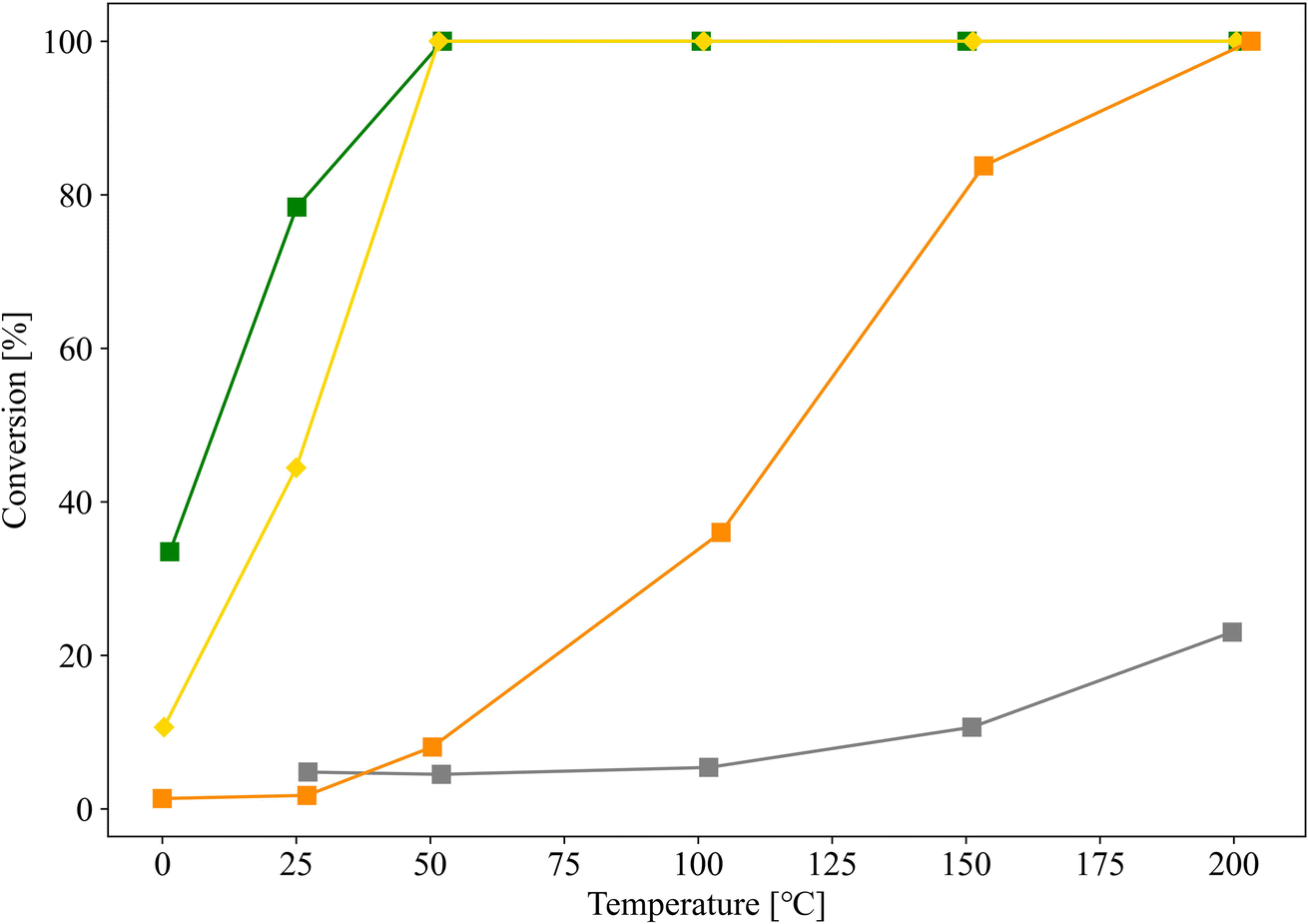 | ||
| Fig. 6 CO conversion curves of Au/SZ-NPG (entry 4, yellow), Au/TiO2 (entry 6, green), Au/ZrO2 (entry 7, orange), and Au/SiO2 (entry 8, grey). | ||
The reasons for the effectiveness of the Au nanoparticles supported on SZ-NPG, which mainly comprises inert oxides (SiO2 and ZrO2), in the development of CO oxidation activity were discussed. One reason is the high hydrophilicity of SZ-NPG.13,25 The presence of water enhances the CO oxidation activity of Au catalysts,19 and the water layer provided by SZ-NPG is effective in this regard.13,25 In addition, the CO oxidation activity can be influenced by the trace elements added to the SZ-NPG. As shown by the TOFs, the activities of entries 7 and 8 (Au/SiO2 and Au/ZrO2) are lower than those of the Au/SZ-NPG samples. In contrast, the activities of entries 6 and 9 (Au/TiO2) are comparable to those of the Au/SZ-NPG samples. The SZ-NPG include TiO2 as trace components, and the Au/TiO2 system is highly active; hence, even the addition of a small amount of TiO2 will improve the activity.
To verify this hypothesis, samples with similar pore properties, differing only in the presence or absence of TiO2 (entries 10 and 11, respectively), were prepared, and their CO oxidation activities were evaluated. The Au nanoparticles in the samples for entries 10 and 11 were supported by the same procedure of the sample for entry 4, and the Au loading of these samples was 1.0 wt%. The pore properties of supports used for entries 10 and 11 were almost similar, but they were different from that of SZ-NPG. Fig. 7 shows the results, along with those of entries 6 (Au/TiO2) and 7 (Au/ZrO2) for comparison. Although the sample without TiO2 (entry 11) also exhibits CO oxidation activity, it is lower than that of the sample with TiO2 (entry 10). The activities of the samples used in entries 10 and 11 are superior to that of the sample used in entry 7 (Au/ZrO2), whereas they are inferior to that of the sample used in entry 6 (Au/TiO2).
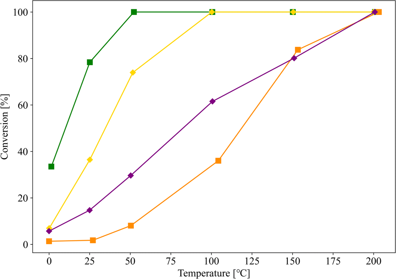 | ||
| Fig. 7 CO conversion curves of Au/SZ-NPG with (entry 10, yellow) and without (entry 11, purple) TiO2. The results of entries 6 (green) and 7 (orange) are shown for comparison. | ||
The activity and durability of Au catalysts are related to the basicity and hydrophilicity of the catalyst support.16 This is because these factors affect the stability of reaction intermediates such as adsorbed CO32− and CO. As SZ-NPG is a highly acidic material, the addition of TiO2, which is basic, is effective. Na2O and K2O, which are also added in trace amounts, are considered effective because they are highly basic and hydrophilic. A previous study by Dien et al.23 has shown that the addition of K cations to Au/SiO2 catalysts increases the dispersion and activity of Au nanoparticles. Although SZ-NPG is acidic, these trace elemental species (Ti, Na, and K) will form localised areas with strong basicity, resulting in high CO oxidation activity. Thus, the catalytic activity of a chemically stable porous glass will be enhanced by mixing active elemental species as trace components and compositing them with Au nanoparticles.
4. Conclusion
We demonstrated that Au nanoparticles can be supported on the SZ-NPG, which was highly acid- and alkali-resistant and chemically stable, using alkali impregnation method. The catalytic activity of Au/SZ-NPG in CO oxidation was higher than that of Au/ZrO2 and Au/SiO2. In fact, Au/SZ-NPG had a similar activity to Au/TiO2 catalysts per active site. Although the catalytic activities of Au nanoparticles are widely known, few studies using nanoporous glasses as supports have been published, and none have reported a high catalytic activity comparable to that of Au/TiO2. The high catalytic activity of Au/SZ-NPG is due to the trace components in SZ-NPG such as TiO2. These trace elements create an effective water–rich reaction field and increase local basicity, which facilitates the CO oxidation by the Au nanoparticles. The CO conversion curves of Au/SZ-NPG were, however, inferior to those of Au/TiO2. The CO conversion did not exceed 50% at room temperature because the average diameter of the supported Au nanoparticles was 7 nm, which was more than twice those of the Au/TiO2 samples prepared using the optimised method. Therefore, further optimisation of the Au nanoparticle sizes on the porous glass and the pore properties of the glass should result in an excellent catalytic system for use in CO removal or sensing. To achieve this, it is necessary to detect local acidity and basicity and elucidate their influence on the growth of Au particles and CO oxidation activity; these are important considerations for future work. SZ-NPG is a promising material for supporting Au catalysts, and our study clearly demonstrates that the catalytic properties can be significantly enhanced by trace components.Author contributions
K. T., M. T., H. S., T. J., and Y. M. conceived the study. M. T., T. T., and M. I. prepared the nanoporous glasses. H. S. and Y. M. supported the Au nanoparticles to oxides and glasses. K. T. and Y. M. characterised the prepared samples and measured their catalytic activities. K. T. analysed the data with input from M. T., H. S., and Y. M. All authors discussed the results and commented on the manuscript, which was written by K. T.Conflicts of interest
There are no conflicts to declare.Acknowledgements
The authors appreciate the technical support provided by Ms Fujiko Arai and Ms Michiko Makino.References
- C. Yang, C. Zhang, Z.-J. Chen, Y. Li, W.-Y. Yan, H.-B. Yu and L. Liu, ACS Appl. Mater. Interfaces, 2021, 13, 7227–7237, DOI:10.1021/acsami.0c20832
.
- T. Dey and D. Naughton, Mater. Res. Bull., 2019, 116, 126–130, DOI:10.1016/j.materresbull.2019.04.027
- M. A. Mazo, J. Sanguino, I. Martín-Gullón and J. Rubio, Microporous Mesoporous Mater., 2021, 323, 111168, DOI:10.1016/j.micromeso.2021.111168
- H. Yao, X. Ding, Z. Wang, F. Zhang, Y. Wang and G. Luo, RSC Adv., 2016, 6, 112413–112419, 10.1039/c6ra21657a
- T. Yoshikawa, K. Kasamatsu, T. Kanata, N. Hirai, T. Tanaka and K. Mori, J. Jpn. Inst. Met., 2011, 75, 665–670, DOI:10.2320/jinstmet.75.665
- H. Khan, M. Seth, S. Samanta and S. Jana, J. Sol-Gel Sci. Technol., 2020, 94, 141–153, DOI:10.1007/s10971-019-05108-x
- S. Wohlrab, A. Janz, M.-M. Pohl, S. Kreft, D. Enke, A. Koeckritz, A. Martin and B. Luecke, Stud. Surf. Sci. Catal., 2010, 175, 315–319, DOI:10.1016/S0167-2991(10)75050-3
- H. L. K. S. Stolle, F. Garwe, R. Müller, T. Krech, B. Oberleiter, T. Rainer, W. Fritzsche and A. Stolle, RSC Adv., 2018, 8, 30289–30297, 10.1039/c8ra03661f
- P. Yan, X. Zhang, X. Wang and X. Zhang, Langmuir, 2020, 36, 5271–5279, DOI:10.1021/acs.langmuir.0c00629
- L.-F. Gutiérrez, S. Hamoudi and K. Belkacemi, Catalysts, 2011, 1, 97–154, DOI:10.3390/catal1010097
- H. Wu, G. Pantaleo, A. M. Venezia and L. F. Liotta, Catalysts, 2013, 3, 774–793, DOI:10.3390/catal3040774
- M. Rafti, A. Brunsen, M. C. Fuertes, O. Azzaroni and G. J. A. A. Soler-Illia, ACS Appl. Mater. Interfaces, 2013, 5, 8833–8840, DOI:10.1021/am403836f
- M. Tsujiguchi, Y. Kii, T. Aitoku, M. Iwao and Y. Y. Maruo, ACS Omega, 2023, 8, 7874–7882, DOI:10.1021/acsomega.2c07622
- M. Haruta, T. Kobayashi, H. Sano and N. Yamada, Chem. Lett., 1987, 16, 405–408 CrossRef
- G. J. Hutchings, J. Catal., 1985, 96, 292–295, DOI:10.1016/0021-9517(85)90383-5
- T. Ishida, T. Murayama, A. Taketoshi and M. Haruta, Chem. Rev., 2020, 120, 464–525, DOI:10.1021/acs.chemrev.9b00551
- M. Sankar, Q. He, R. V. Engel, M. A. Sainna, A. J. Logsdail, A. Roldan, D. J. Willock, N. Agarwal, C. J. Kiely and G. J. Hutchings, Chem. Rev., 2020, 120, 3890–3938, DOI:10.1021/acs.chemrev.9b00662
- T. Fujitani and I. Nakamura, Angew. Chem., Int. Ed., 2011, 50, 10144–10147, DOI:10.1002/anie.201104694
- J. Saavedra, H. A. Doan, C. J. Pursell, L. C. Grabow and B. D. Chandler, Science, 2014, 345, 1599–1602, DOI:10.1126/science.1256018
- H. Koga, K. Tada and M. Okumura, J. Phys. Chem. C, 2015, 119, 25907–25916, DOI:10.1021/acs.jpcc.5b07633
- S. Tsubota, D. A. H. Cunningham, Y. Bando and M. Haruta, Stud. Surf. Sci. Catal., 1995, 91, 227–235, DOI:10.1016/S0167-2991(06)81759-3
- Y. Maeda, T. Akita and M. Kohyama, Catal. Lett., 2014, 144, 2086–2090, DOI:10.1007/s10562-014-1376-4
- L. X. Dien, T. Ishida, A. Taketoshi, D. Q. Truong, H. D. Chinh, T. Honma, T. Murayama and M. Haruta, Appl. Catal., B, 2019, 241, 539–547, DOI:10.1016/j.apcatb.2018.09.053
- Y. Maeda, N. Taguchi, T. Akita and M. Kohyama, Catal. Lett., 2016, 146, 2376–2380, DOI:10.1007/s10562-016-1870-y
- M. Tsujiguchi, T. Aitoku, H. Takase and Y. Y. Maruo, IEEE Sens. J., 2021, 21, 8868–8877, DOI:10.1109/JSEN.2021.3055264
- T. Yazawa, H. Tanaka, K. Eguchi and S. Yokoyama, J. Mater. Sci., 1994, 29, 3433–3440, DOI:10.1007/BF00352046
- H. Sakurai, K. Koga, Y. Iizuka and M. Kiuchi, Appl. Catal., A, 2013, 462–463, 236–246, DOI:10.1016/j.apcata.2013.05.016
- H. Sakurai, K. Koga and M. Kiuchi, Catal. Today, 2015, 251, 96–102, DOI:10.1016/j.cattod.2014.11.004
- K. Tada, Y. Maeda, H. Koga and M. Okumura, Chem. Lett., 2018, 47, 200–203, DOI:10.1246/cl.170989
- T. Ishida, M. Nagaoka, T. Akita and M. Haruta, Chem.–Eur. J., 2008, 14, 8456–8460, DOI:10.1002/chem.200800980
- H. Tanaka, Yogyo Kyokaishi, 1977, 85, 587–590 CrossRef CAS
- M. Haruta, Catal. Today, 1997, 36, 153–166, DOI:10.1016/S0920-5861(96)00208-8
- M. Haruta, Faraday Discuss., 2011, 152, 11–32, 10.1039/C1FD00107H
- K. Tada, H. Koga, A. Hayashi, Y. Kondo, T. Kawakami, S. Yamanaka and M. Okumura, Bull. Chem. Soc. Jpn., 2017, 90, 506–519, DOI:10.1246/bcsj.20160359
- B. L. Moroz, P. A. Pyrjaev, V. I. Zaikovskii and V. I. Bukhtiyarov, Catal. Today, 2009, 144, 292–305, DOI:10.1016/j.cattod.2008.10.038
- E. D. Martínez, C. Boissière, D. Grosso, C. Sanchez, H. Troiani and G. J. A. A. Soler-Illia, J. Phys. Chem. C, 2014, 118, 13137–13151, DOI:10.1021/jp500429b
- T. Takei, T. Akita, I. Nakamura, T. Fujitani, M. Okumura, K. Okazaki, J. Huang, T. Ishida and M. Haruta, Adv. Catal., 2012, 55, 1–126, DOI:10.1016/B978-0-12-385516-9.00001-6
- H. Murayama, T. Hasegawa, Y. Yamamoto, M. Tone, M. Kimura, T. Ishida, T. Honma, M. Okumura, A. Isogai, T. Fujii and M. Tokunaga, J. Catal., 2017, 353, 74–80, DOI:10.1016/j.jcat.2017.07.002
- K. Tada, K. Sakata, Y. Kitagawa, T. Kawakami, S. Yamanaka and M. Okumura, Chem. Phys. Lett., 2013, 579, 94–99, DOI:10.1016/j.cplett.2013.06.023
- K. Tada, H. Koga, M. Okumura, A. Hayashi, Y. Ato, T. Kawakami and S. Yamanaka, e-J. Surf. Sci. Nanotechnol., 2018, 16, 267–273 CrossRef CAS
- T. Akita, K. Tanaka, M. Kohyama and M. Haruta, Catal. Today, 2007, 122, 233–238, DOI:10.1016/j.cattod.2007.01.014
- L. F. Allard, A. Borisevich, W. Deng, R. Si, M. Flytzani-Stephanopoulos and S. H. Overbury, J. Electron Microsc., 2009, 58, 199–212, DOI:10.1093/jmicro/dfp016
| This journal is © The Royal Society of Chemistry 2024 |