DOI:
10.1039/D3RA04257J
(Paper)
RSC Adv., 2024,
14, 5022-5036
A novel flexible CO2 gas sensor based on polyvinyl alcohol/yttrium oxide nanocomposite films
Received
25th June 2023
, Accepted 22nd January 2024
First published on 8th February 2024
Abstract
Polyvinyl alcohol/yttrium oxide (PVA/Y2O3) nanocomposite films with five different weight ratios of PVA and Y2O3 nanoparticles (NPs) were prepared using a simple solution casting method. The prepared polymer nanocomposite (PNC) films were examined using Fourier transform infrared (FTIR) spectroscopy, X-ray diffraction (XRD), scanning electron microscopy (SEM), and thermogravimetric analysis (TGA). FTIR spectra exhibited a strong interaction between the PVA matrix and Y2O3 NPs. SEM results indicated that Y2O3 NPs were properly dispersed in the PVA matrix. The thermal stability of the PVA/Y2O3 nanocomposite films was found to be dependent on Y2O3 NP loading (wt%) in the nanocomposite films. Furthermore, chemiresistive gas sensing properties of the PVA/Y2O3 nanocomposite films were evaluated and the sensing parameters including sensing response, operating temperature, selectivity, stability, response/recovery time, and repeatability were systematically investigated based on the change in electrical resistance of the nanocomposite film in the presence of carbon dioxide (CO2) gas. The maximum sensing response (S) of 92.72% at a concentration of 100 ppm under an optimized operating temperature of 100 °C with a fast response/recovery time of ∼15/11 s towards CO2 gas detection was observed for the PVA/Y2O3 nanocomposite film with 5 wt% loading of Y2O3 NPs in the PVA matrix. The finding in this work suggest that Y2O3 NPs are sufficiently fast as a CO2 gas sensing material at a relatively low operating temperature. Moreover, the key role of the Y2O3 NPs in modulating the electrical and gas sensing properties of the PVA matrix is discussed here.
1 Introduction
Environmental monitoring, safety, and process control are largely dependent on the qualitative and quantitative analysis of chemical substances that exist in the environment. One of the most significant tools for detecting chemical variations in the environment is by utilizing chemical gas sensors.1–5 Carbon dioxide (CO2) is one of the most common greenhouse gas emissions evolved from the combustion processing and burning of fossil fuels in electric power generators. Automobiles also produce exhaust gases such as CO2 that are predominantly responsible for increasing global warming and climate change, resulting in environmental concerns and adverse effects to human health.6–8 CO2 plays a prominent role in ocean acidification, as it dissolves in water at mild pressure and temperatures to form carbonic acid, which has drawn serious attention in environmental monitoring.9 In particular, CO2 is a major greenhouse gas (GHG) in the earth's atmosphere, and its concentration has increased from 280 ppm (i.e., parts per million) to over 415.7 ppm (i.e., about 0.04% by volume) since the pre-industrial times.10,11 According to a new report from the United Nations (UN's) – World Meteorological Organization (WMO), the increase in CO2 levels in our atmosphere from 2020 to 2021 was also larger than the average annual growth rate over the last decade, and the levels continue to rise through 2022.12 Currently, the CO2 concentration levels in outdoor air pollution typically range from 300 to 400 ppm (0.03% to 0.04% by volume). It can be increase up to the range from 600 to 900 ppm in metropolitan areas but not be harmful to human health.10 According to the “Occupational Safety and Health Administration (OSHA)” and the “American Conference of Governmental Industrial Hygienists (ACGIH)”, the current recommended Permissible Exposure Limit (PEL) and Threshold Limit Value (TLV) for CO2 concentrations is 5000 parts per million (ppm) parts of air (9000 milligrams per cubic meter (mg m−3)) in an 8 – hour work day (Time-weighted average (TWA)).10,13,14
According to the guidelines of the “National Institute for Occupational Safety and Health (NIOSH)”, the current Recommended Exposure Limit (REL) for CO2 concentrations is 5000 ppm (9000 mg m−3) as an 10 – hour work day (TWA). Furthermore, 30![[thin space (1/6-em)]](https://www.rsc.org/images/entities/char_2009.gif) 000 ppm (54000 mg m−3) is the Recommended Exposure Limit – Short Term Exposure Limit (REL-STEL) based on a 15 minutes Time-weighted average (TWA) exposure as long as the 10 – hour work day (TWA) is not exceeded. The “OSHA, NIOSH, and ACGIH” recognizes CO2 as a strong asphyxiant and toxic contaminant.15 Certainly above the PEL (i.e., CO2 concentrations higher than 5000 ppm), resulting in a wide range of harmful health effects on the human body, such as headache, difficulty in breathing, elevated blood pressure, increased heart rate, dizziness, asphyxia, convulsions, cardiac output, lung diseases, kidney failure, coma and death.16,17 Therefore, CO2 gas detection is a basic need of modern life to know the increasing rate of CO2 emissions in the environment to reduce the impact of air pollution, which is detrimental to human health and accountable for the world's largest health and environmental problems.18 The CO2 gas sensor plays a significant role in air pollution monitoring for environmental issues, and helps in regulating the indoor/outdoor air quality.19 The CO2 gas concentration of the atmosphere is commonly measured using an electrochemical sensor, optical sensor, quartz-crystal microbalance (QCM) sensor, surface acoustic wave (SAW) sensor, non-dispersive infrared (NDIR) sensor and chemiresistive sensor.18,20–22 However, these sensors suffer from various limitations, such as high cost, bigger size, high operating temperature, poor selectivity, less reproducibility, contamination issues, non-reliability, and complex configuration of the sensor.15
000 ppm (54000 mg m−3) is the Recommended Exposure Limit – Short Term Exposure Limit (REL-STEL) based on a 15 minutes Time-weighted average (TWA) exposure as long as the 10 – hour work day (TWA) is not exceeded. The “OSHA, NIOSH, and ACGIH” recognizes CO2 as a strong asphyxiant and toxic contaminant.15 Certainly above the PEL (i.e., CO2 concentrations higher than 5000 ppm), resulting in a wide range of harmful health effects on the human body, such as headache, difficulty in breathing, elevated blood pressure, increased heart rate, dizziness, asphyxia, convulsions, cardiac output, lung diseases, kidney failure, coma and death.16,17 Therefore, CO2 gas detection is a basic need of modern life to know the increasing rate of CO2 emissions in the environment to reduce the impact of air pollution, which is detrimental to human health and accountable for the world's largest health and environmental problems.18 The CO2 gas sensor plays a significant role in air pollution monitoring for environmental issues, and helps in regulating the indoor/outdoor air quality.19 The CO2 gas concentration of the atmosphere is commonly measured using an electrochemical sensor, optical sensor, quartz-crystal microbalance (QCM) sensor, surface acoustic wave (SAW) sensor, non-dispersive infrared (NDIR) sensor and chemiresistive sensor.18,20–22 However, these sensors suffer from various limitations, such as high cost, bigger size, high operating temperature, poor selectivity, less reproducibility, contamination issues, non-reliability, and complex configuration of the sensor.15
In the last decade, scientific communities and researchers worldwide have focused on actively engaging in the development of a suitable CO2 sensing material that can efficiently work at room temperature (RT) or at lower temperature for detecting CO2 gas at lower concentrations (i.e., ppm) to reduce its direct effect on Earth's atmosphere, such as global warming, ozone-layer depletion, acid rain and other hazardous processes.22 RT sensors also have advantages like lower power consumption, sustainable, and portability. In these scenarios, chemiresistive sensors are in high demand owing to their numerous advantages, including their small size, compatibility with DC circuits, ease of operation, low production cost, simple electronic interface, low maintenance, high reliability and facile sensing technology to achieve improved sensing responses and selectivity to the target CO2 gas. To date, chemiresistive sensors have been fabricated using various sensing materials as a transducing platform for gas detection, including semiconducting metal oxides (SMOx), intrinsically conducting polymers (ICPs), and conducting polymers composites (CPCs). Other new materials also have been widely investigated for an ideal yet economic transducing platform with improved sensing parameters for CO2 gas sensing as an ongoing research topic in materials science and engineering fields for real-world application. The majority of single SMOx sensing materials-based chemiresistive sensors can alleviate these issues: either poor selectivity or poor gas interaction with active sensing materials under ambient conditions, need of elevated operating temperature, low sensing response, long-term stability, and reversibility. On the other hand, CPCs-sensing materials have limited sensing response and selectivity, making it more challenging to use them in real-time applications.9,23–25 Moreover, some literature reports pointed out that the combination of SMOx with polymer materials is a relatively new approach to reduce the working temperature of the sensor that can significantly improve the gas sensing performances, such as sensing response and selectivity. Taking inspiration from these concepts, our investigation delved into understanding how Y2O3 nanoparticles influence the CO2 sensing properties of the non-conducting PVA matrix. It was anticipated that the combined effects of Y2O3 nanoparticles and the PVA polymer matrix could pave the way for substantial enhancements in gas sensing performance. PVA is a well-known, water-soluble synthetic polymer with advantageous properties, such as low cost, non-toxicity, ease of manufacturing, high optical transparency, good biocompatibility, chemical stability, and excellent mechanical qualities.26 PVA has also been broadly used in various applications by paper industries, synthetic fiber, textile industries, contact lens, binder industries and coating due to its solubility in water, excellent chemical and physical properties, excellent film formation, and good chemical resistance.27–29 PVA is made up of a carbon chain network with hydroxyl groups of semi-crystalline nature that contribute to the development of polymer complexes by providing a source of hydrogen bonding.30 Among various rare earth materials, Y2O3 NPs have recently received a lot of attention with several promising physical properties, such as its crystallographic stability up to 2325 °C (melting point of Y2O3 NPs is 2450 °C), high thermal conductivity (0.13 W cm−1 K−1), high mechanical strength, and large optical band gap (5.5 eV).31 Furthermore, Y2O3 possesses a broad band gap of 5.6 eV and work function of 2.0 eV, as a metal oxide known for its robust adsorption selectivity. Y2O3 NPs have emerged as highly promising candidates for utilization in gas sensors owing to their exceptional adsorption selectivity, and high thermal and chemical stability.32
In the present work, we report the easy synthesis route for obtaining PVA/Y2O3 nanocomposite films by reinforcing Y2O3 NPs in a PVA matrix using the solution casting process. The effect of Y2O3 NPs wt% loading in the PVA matrix was widely examined to study the changes in the structure, surface morphology, and CO2 gas sensing properties. This study demonstrates the synthesis of novel PVA/Y2O3 nanocomposite films and their implementation in the design and fabrication of a chemiresistive gas sensor device. Moreover, the sensing response, selectivity, response/recovery time, repeatability, and long-term performance of PVA/Y2O3 nanocomposite films have been reported in detail for the different loading of Y2O3 NPs in PVA matrix to understand the synergistic effects between them. The experimental results revealed that the reinforcement of Y2O3 NPs in the PVA matrix plays a vital role in improving the gas sensing efficiency of the resulting nanocomposites to detect CO2 gas concentrations with regards to lower working temperature, higher gas sensing response, selectivity, and lower response/recovery time. These binary nanocomposite films act as n-type semiconductors with high mobility and chemical stability, which play a lead role in enhanced CO2 gas detection. The novel PVA/Y2O3 nanocomposite film-based chemiresistive gas sensor devices show high sensing response and accurate selectivity with parts per million (ppm) levels of CO2 gas detection at low operating temperature (100 °C), and is a significant step in controlling its concentration in many wide ranges of applications and environmental monitoring.
2 Materials and methods
2.1 Materials
PVA with a molecular weight (MW) in the range of 5000–1,24000 g mol−1 and 86–89% degree of hydrolysis was procured from SD Fine Chem. Ltd, Mumbai, India. Y2O3 NPs (50–70 nm) were obtained from Alfa Aesar. Deionized water was used as a solvent throughout the experimental work.
2.2 Synthesis of the PVA/Y2O3 nanocomposite films
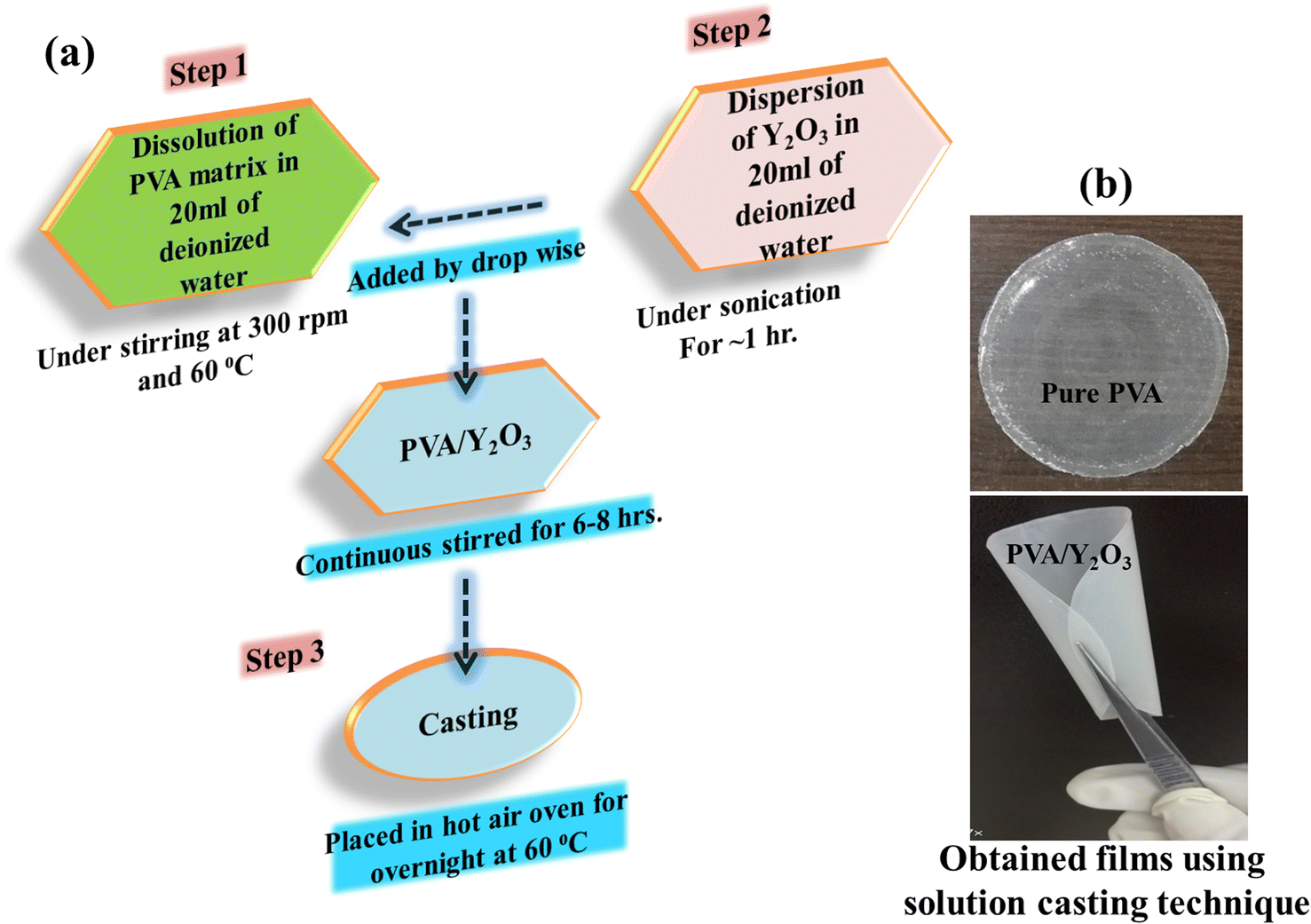
Firstly, the desired quantity of PVA was dissolved in 20 ml of deionized water by heating at 60 °C until the solution became homogeneous. The dissolved PVA solution was allowed to cool down to room temperature (RT) under continuous stirring. Secondly, a required amount of Y2O3 NPs was dispersed in 20 ml of deionized water under sonication for ∼1 hour. Then, the dispersed Y2O3 NPs were added to the dissolved PVA solution, and the resulting PVA/Y2O3 mixture was kept under vigorous stirring (500 rpm) for 6–8 hours in order to achieve proper mixing of the polymer matrix and nanofiller. Finally, the mixed PVA/Y2O3 solution was poured onto a Teflon Petri dish and left overnight in a hot air oven at 60 °C to facilitate solvent evaporation. This process led to the creation of PVA/Y2O3 nanocomposite films, which were subsequently peeled off from the Teflon Petri dish, as illustrated in Fig. 1a. Fig. 1b provides evidence of the successful formation of flexible films, showcasing the homogeneous dispersion of Y2O3 nanoparticles within the pure PVA. Additionally, using a screw gauge, the thickness of the resulting nanocomposite films was measured to be in the range of 60–80 μm.
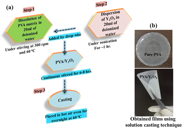 |
| | Fig. 1 (a) Experimental protocol for the synthesis of PVA/Y2O3 nanocomposite films using solution casting technique. (b) Optical images of the prepared samples. | |
2.3 Characterization
FTIR spectra of pure PVA, Y2O3 NPs and the PVA/Y2O3 nanocomposite films were measured using an FTIR spectrophotometer (Bruker, Alpha E) in the wavenumber range of 500–4000 cm−1. X-ray diffraction patterns of pure PVA, Y2O3 NPs and the PVA/Y2O3 nanocomposite films were acquired using an X-ray diffractometer (Bruker AXS D8). The scans rate was taken in the 2θ range from 10–90° using Cu Kα radiation of wavelength λ = 1.540 Å. The surface micrographs of pure PVA, Y2O3 NPs and the PVA/Y2O3 nanocomposite films were examined using a Scanning electron microscope (SEM) (JEOL JSM-6480 LV) by applying a voltage of 30 kV. The thermal stability of pure PVA, Y2O3 NPs, and the PVA/Y2O3 nanocomposite films was investigated using a thermogravimetric analyzer (TGA) (Shimadzu TGA-50). The samples were heated from RT to 1000 °C with a 10 °C per min heating rate.
2.4 Gas sensing measurements
Gas sensing measurements were performed using a homemade dynamic gas sensing system consisting of a 0.8 L Pyrex chamber, which contains a substrate holder connected to a ceramic heater. A schematic diagram of the sensing characterization has been reported in our previous work.33 Primarily, two silver point contacts were coated using commercial silver paint. The sample with contacts was placed on the substrate holder, and the chamber was purged with N2 for 30 min to remove air from the chamber. Secondarily, the desired sensor operation temperature was programmed (60 to 100 °C). Once the desired temperature was maintained for 15 min, different concentrations of CO2 were purged into the chamber utilizing a CO2 calibrated mass flow controller. The corresponding changes were registered automatically using a Fluke 289 multimeter, which is connected to a computer. The gas sensing response, response time, and recovery time were calculated using the standard formulas shown in Eq. (1)–(3). The response and recovery times were considered from 10% and 90% changes of the dynamic response curve.| | |
Sensing response (%) = (RCO2 − RN2)/RCO2 × 100%
| (Eq. 1) |
| | |
Response time = 10% Tini − 90% Tmax1
| (Eq. 2) |
| | |
Recovery time = 90% Tmax2 − 10% Tfin
| (Eq. 3) |
RCO2 and RN2 are the surface resistance of thin films before and after exposure to CO2, respectively. Tini and Tmax1 are the time measurements of 10% and 90% after CO2 was purged into the chamber, respectively. Finally, Tfin and Tmax2 are the time measurements of 10% and 90% after CO2 was removed, respectively.
3 Results and discussion
3.1 FTIR
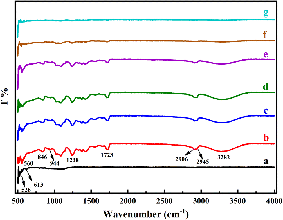
In Fig. 2, the FTIR spectra of the pure Y2O3 NPs, PVA, and PVA/Y2O3 nanocomposite films with different weight ratios are presented. From Fig. 2b, an intense O–H stretching vibration band of pure PVA was observed at 3282 cm−1. The transmission bands at 2906 cm−1 and 2945 cm−1 are attributed to the symmetric and asymmetrical stretching vibrations of C–H, respectively. The absorption band appeared at 1723 cm−1 of PVA due to the C![[double bond, length as m-dash]](https://www.rsc.org/images/entities/char_e001.gif) O vinyl acetate group. The peak observed at 1238 cm−1 of PVA corresponds to the wagging vibrations of the C–H groups. The absorption bands at 944 cm−1 and 846 cm−1 are attributed to the skeletal vibrations of PVA.34–36 The characteristic peaks at 526 cm−1 and 613 cm−1 of Y2O3 NPs correspond to the Y–O stretching, as shown in Fig. 2a.36 From the figure, it is observed that the entire FTIR spectra of PVA were reduced when the content of Y2O3 NPs increased, and this is clearly shown in Fig. 2c–g. According to the current data, there is a strong intermolecular interaction between the PVA matrix and Y2O3 NPs. As the gas sensing process is completely superficial, the presence of additional function groups may reduce the surface process adsorption and desorption of the molecules, unless the functional groups favor the test gas molecule adsorption.
O vinyl acetate group. The peak observed at 1238 cm−1 of PVA corresponds to the wagging vibrations of the C–H groups. The absorption bands at 944 cm−1 and 846 cm−1 are attributed to the skeletal vibrations of PVA.34–36 The characteristic peaks at 526 cm−1 and 613 cm−1 of Y2O3 NPs correspond to the Y–O stretching, as shown in Fig. 2a.36 From the figure, it is observed that the entire FTIR spectra of PVA were reduced when the content of Y2O3 NPs increased, and this is clearly shown in Fig. 2c–g. According to the current data, there is a strong intermolecular interaction between the PVA matrix and Y2O3 NPs. As the gas sensing process is completely superficial, the presence of additional function groups may reduce the surface process adsorption and desorption of the molecules, unless the functional groups favor the test gas molecule adsorption.
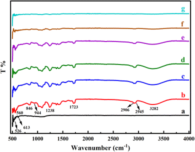 |
| | Fig. 2 FTIR spectra of (a) pure Y2O3 NPs, (b) pure PVA and PVA/Y2O3 nanocomposite films with different weight ratios: (c) 95/5 wt%, (d) 90/10 wt%, (e) 85/15 wt%, (f) 80/20 wt%, and (g) 75/25 wt%. | |
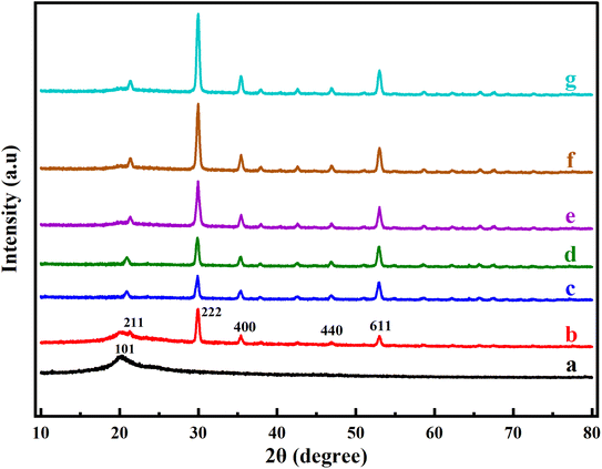
3.2 XRD
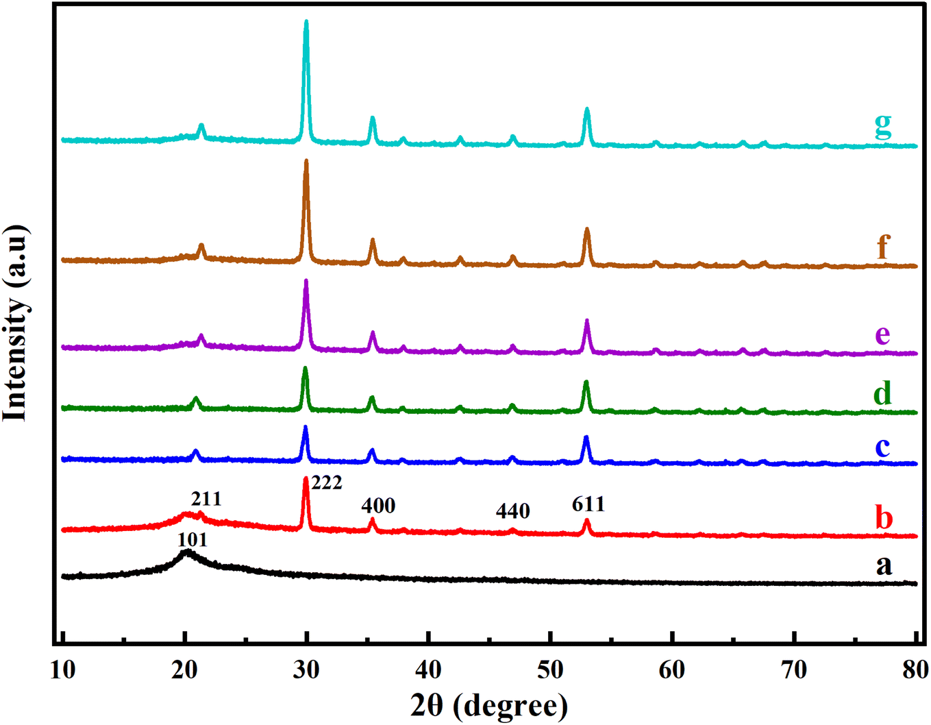
Fig. 3 shows the X-ray diffraction measurements for pure PVA, Y2O3 NPs and the PVA/Y2O3 nanocomposite films at various Y2O3 NPs weight ratios (5 wt%, 10 wt%, 15 wt%, 20 wt%, and 25 wt%). Fig. 3a shows a broad diffraction peak at 2θ = 19.98° corresponding to plane (101) that exhibits the semi-crystalline monoclinic structure of the pure PVA film, which is consistent with the existing literature.34–38 This is attributed to the existence of a high degree of hydrogen bonding interaction between the hydroxyl groups.39 The XRD pattern of Y2O3 NPs exhibits five major characteristic peaks at 2θ = 20.40°, 29.96°, 35.41°, 46.92°, and 53.02° corresponding to the (211), (222), (400), (440), and (611) crystal planes, respectively, as shown in Fig. 3b. These patterns of Y2O3 NPs match the cubic crystal structure provided in ICDD PDF 41-1105 quite well, and the data presented in the literature also agree very well.40–42 It can be observed from Fig. 3c–g that the intensity of all diffraction peaks of Y2O3 NPs increased with the increased Y2O3 NPs wt% and decreased PVA wt% in the PVA/Y2O3 nanocomposite films. Thus, as the Y2O3 NPs is increased, the intensity of the diffraction peak becomes stronger, confirming the increased crystallization in PVA at high Y2O3 NPs loadings. The XRD results not only confirm the presence of Y2O3 nanoparticles but also reveal that the crystalline structure of PVA is slightly improved by the integration of Y2O3.
 |
| | Fig. 3 XRD patterns of (a) pure PVA, (b) pure Y2O3 NPs, and PVA/Y2O3 nanocomposite films with different weight ratios: (c) 95/5 wt%, (d) 90/10 wt%, (e) 85/15 wt%, (f) 80/20 wt%, and (g) 75/25 wt%. | |
3.3 SEM
The surface morphologies of the pure Y2O3 NPs and PVA/Y2O3 nanocomposite films with different ratios were investigated using SEM, as shown in Fig. 4. Fig. 4a depicts the SEM micrographs of pure Y2O3 NPs, and no large agglomeration was found. Fig. 4b–e displays the micrographs of the PVA/Y2O3 nanocomposite films with different ratios at 95/5 wt%, 90/10 wt%, 85/15 wt%, and 80/20 wt%. Fig. 4b demonstrates that the Y2O3 NPs is simply dispersed throughout the polymer matrix. Upon increasing the Y2O3 NPs content in the PVA/Y2O3 nanocomposites, an increased dispersion of Y2O3 NPs in the polymer matrix was observed, as shown in Fig. 4c–e. When associated with the surface of pure Y2O3 NPs (Fig. 4a), the nanocomposite shows uniform morphology. This was ascribed to the homogeneous dispersion of Y2O3 NPs within the PVA matrix by hydrogen bonding. The morphology of the sample is an important factor for the gas sensing of metal oxide nanoparticles. As the surface particle size decreases, the possessing of a rougher and porous surface is more favorable for the gas sensing because a high absorption occurs with higher surface area. It can be seen that smoother surfaces were obtained with increased yttrium oxide nanoparticles. Corresponding optical images of the PVA/Y2O3 nanocomposite films are shown in the inset of the SEM micrographs.
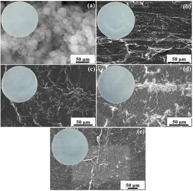 |
| | Fig. 4 SEM micrographs of (a) pure Y2O3 NPs, and PVA/Y2O3 nanocomposite films with different ratios: (b) 95/5 wt%, (c) 90/10 wt%, (d) 85/15 wt%, and (e) 80/20 wt%. | |
3.4 TGA
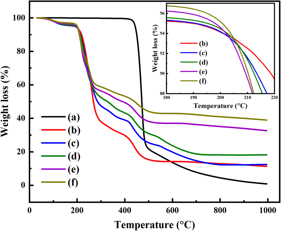
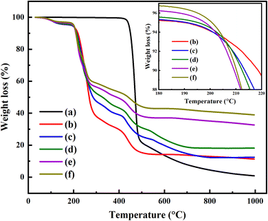
The TGA analysis of the pure PVA and PVA/Y2O3 nanocomposite films with different weight ratios of Y2O3 NPs is given in Fig. 5. The TGA measurements of pure PVA exhibited a one-step decomposition phenomenon. There was no weight loss observed from RT to 420 °C, which showed that the samples had high thermal stability.34,43 Fig. 5a shows that the decomposition of pure PVA starts from 420 °C to 503 °C, which is attributed to the degradation of the polymer chain. The corresponding weight loss of pure PVA was about 81.3%. After the addition of different wt% of Y2O3 NPs, the degradation of the PVA/Y2O3 nanocomposite films exhibited three steps, as seen in Fig. 5b–f. The first decomposition step of the PVA/Y2O3 nanocomposite films starts from ∼63 °C to ∼148 °C. The corresponding weight loss is about 3%, which can be attributed to the evaporation of absorbed water molecules from the surface. The second decomposition step of the PVA/Y2O3 nanocomposite films between 190 °C and 369 °C (inset of Fig. 5b–f), which is attributed to the loss of water molecules bound to the polymer matrix44 and splitting of the polymer chain.45 The third step appeared between 369 °C and 530 °C, which is due to the decomposition and carbonization of the polymer backbone,44,46 after which the loss rate slows down. The corresponding weight loss of the PVA/Y2O3 nanocomposite films with different ratios of 95/5 wt%, 90/10 wt%, 85/15 wt%, 80/20 wt%, and 75/25 wt% are 65%, 55%, 53%, 47%, and 43% for the second step, and 18%, 15%, 14%, 12%, and 10% for the third step, respectively. As a result, the thermal stability of the PVA/Y2O3 nanocomposite films was decreased compared to the pure PVA. However, a slight increase in thermal stability of the PVA/Y2O3 nanocomposite films was still observed with increasing Y2O3 NPs (5 wt%, 10 wt%, 15 wt%, 20 wt%, and 25 wt%), as shown in Fig. 5.
 |
| | Fig. 5 TGA analysis of (a) pure PVA, and PVA/Y2O3 nanocomposite films with different weight ratios (b) 95/5 wt%, (c) 90/10 wt%, (d) 85/15 wt%, (e) 80/20 wt%, and (f) 75/25 wt%. Inset of Fig. 5 shows the TGA curves of the PVA/Y2O3 nanocomposite films in the temperature range of 180–220 °C. | |
The residual portion occurs at the temperatures between ∼560 °C and 1000 °C, where the pure PVA and PVA/Y2O3 nanocomposite films decompose. The lowest residual production is 0.93% for pure PVA. The residue of the PVA/Y2O3 nanocomposite films with different ratios of 95/5 wt%, 90/10 wt%, 85/15 wt%, 80/20 wt%, and 75/25 wt% is 11.18%, 12.41%, 18.14%, 32.95%, and 38.99%, respectively. It was observed that the residual production is increased with increasing wt% of Y2O3 NPs. This might be associated with the presence of Y2O3 NPs, and changes accordingly with the Y2O3 NPs wt% in the PVA/Y2O3 nanocomposite films.47,48
TGA analysis confirms that the samples were stable until 190 °C, indicating that the sensors obtained based on these materials can be operated until 190 °C without affecting the sensing properties.
4 Gas sensing properties
4.1 CO2 gas sensing mechanism of PVA/Y2O3 nanocomposite film
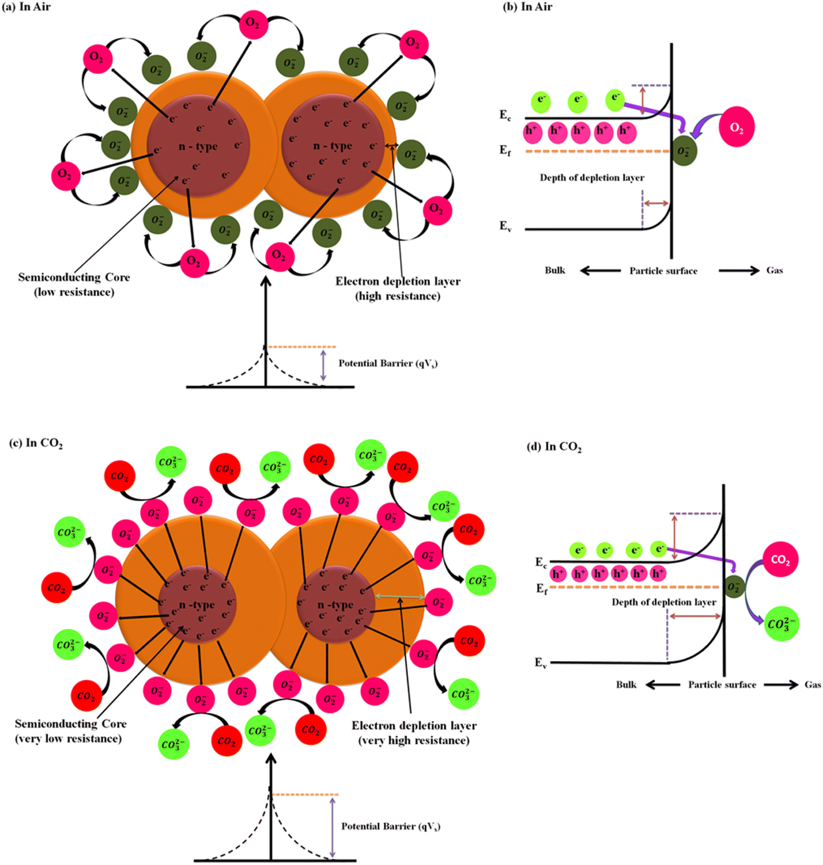
Y2O3 NPs has been identified as an n-type semiconductor metal oxide (SMO) material. Its gas sensing mechanism is mainly governed by three key factors: adsorption, desorption and charge transfer between the target gas molecule and semiconductor surface. When the PVA/Y2O3 nanocomposite films-based chemiresistive sensors are exposed to ambient air, the adsorption of oxygen (O2) molecules species occurs at the active surface area of the Y2O3 NPs. Oxygen molecules may be in either the physisorbed state as uncharged molecules or chemisorbed state as charged species on the Y2O3 NPs surface, which mainly depends on the sensor operation temperature. The oxygen molecules present in ambient air capture a certain amount of free electrons from the conduction band of the Y2O3 NPs material surface during the adsorption process to generate chemisorption oxygen ion species (O2(ads)−,O(ads)−, and O(ads)2−) with an increase in the operating temperature of the PVA/Y2O3 nanocomposite films-based chemiresistive sensors. As a result of this, the width of the electron depletion layer on the surface region of the Y2O3 material increases at a certain depth, which leads to the formation of a thicker electron depletion layer (i.e., increase in the width of the space-charge layer and increase in the height of the potential barrier, as depicted in Fig. 6a and b). The extent of the depletion layer depends on the available oxygen vacancies, as CO2 is an oxidising gas and its adsorption over an n-type semiconductor material like Y2O3 NPs results in the increase in the electrical resistance of the Y2O3 sensor material. This adsorption process can be described by the following equations (Eq. (4)–(7)). Eventually, the air resistance of the PVA/Y2O3 nanocomposite film-based chemiresistive sensor increases upon the exposure to air. The stabilized resistance of the PVA/Y2O3 nanocomposite film-based chemiresistive sensors in the presence of ambient air is known as the “air resistance of the sensor (Rair)”.| | |
O2(gas) ↔ O2(ads)
| (Eq. 4) |
| | |
O2(ads) + e− → O2(ads)− (Topt. ≤ 100 °C)
| (Eq. 5) |
| | |
O2(ads)− + e− → 2O(ads)− (100 °C ≥ Topt. ≤ 300 °C)
| (Eq. 6) |
| | |
O(ads)− + e− → O(ads)2− (Topt. ≥ 300 °C)
| (Eq. 7) |
| | |
CO2 + O(ads)− + e− → CO3(ads)2−
| (Eq. 8) |
 |
| | Fig. 6 A schematic diagram of the CO2 gas sensing mechanisms of n-type semiconducting materials (i.e., Y2O3 NPs) reinforced in PVA/Y2O3 nanocomposite film-based chemiresistive sensors: (a) in the presence of air, and (c) in the presence of CO2 gas. The schematic diagram of the corresponding band structure: (b) in the presence of air, and (d) in the presence of CO2 gas. | |
When PVA/Y2O3 nanocomposite films-based chemiresistive sensors are exposed to an oxidizing test gas such as CO2 gas, the CO2 gas molecules will adsorbed above the active sensing layer of the Y2O3 NPs surface. A chemical interaction reaction takes place between the CO2 gas molecules and the chemisorbed oxygen ions species (O2(ads)−, O(ads)−, and O(ads)2−) present on the active sensing layer of Y2O3 NPs surface, depending on the working temperature of the chemiresistive sensor. This results in the formation of carbonates (CO32−) over the sensor surface, as shown in Eq. (9) and (10). During this reaction process, the CO2 gas molecules have a tendency to withdraw electrons from the conduction band of the Y2O3 material surface. This leads to the formation of a thicker electron depletion layer (i.e., increase in the width of the space-charge layer and increase in the height of the potential barrier, as depicted in Fig. 6c and d) at a certain more depth on the surface region of the Y2O3 materials, and that causes the increase in the electrical resistance of the Y2O3 material. Eventually, the gas resistance of the PVA/Y2O3 nanocomposite film-based chemiresistive sensor significantly increases upon exposure to CO2 gas. The change in the chemiresistive sensor resistance is because of the chemical interaction reaction of the chemisorbed oxygen species present on the active surface area of Y2O3 NPs reacting with the injected CO2 gas molecules, which is known as the “gas resistance of the sensor (Rgas).
| | |
CO2(gas) ↔ CO2(ads)
| (Eq. 9) |
| | |
2CO2(gas) + O2(ads)− + e− → 2CO32− (Topt. = 100 °C)
| (Eq. 10) |
Here, the non-conducting PVA polymer plays no active role in the gas sensing mechanism of the PVA/Y2O3 nanocomposite film-based chemiresistive sensor. The main role of PVA in the PVA/Y2O3 nanocomposite film sensor is to provide a flexible base or substrate for potential applications. Furthermore, the reinforcement of Y2O3 NPs in the PVA/Y2O3 nanocomposite film provides an electrically conductive network pathway between the grain boundaries of Y2O3 NPs. The surface catalytic effects of the Y2O3 NPs facilitate the higher gas adsorption and diffusion rate on the active sensing surface area of the PVA/Y2O3 nanocomposite film, thus leading to significantly improved gas sensing properties of the PVA/Y2O3 nanocomposite film sensor. We have discussed all of our sensing response results at the optimized operating temperature of 100 °C towards 100 ppm of CO2 gas concentration. We have also discussed all of our sensing response results at the typical indoor relative humidity levels in the range between 50–60% (and is rarely below 50% or above 60%) at the optimized operating temperature of 100 °C towards 100 ppm of CO2 gas concentration.
4.2 Effect of Y2O3 NPs loading on the electrical resistances of the PVA/Y2O3 nanocomposite films
The increase in the electrical resistance of the PVA/Y2O3 nanocomposite film indicates the detection of the molecular species of CO2 gas at different gas concentrations. The variation in the electrical resistance of the PVA/Y2O3 nanocomposite films prepared with different wt% filler loading of Y2O3 NPs reinforced in non-conducting PVA polymer matrix, and their implementation in fabricating chemiresistive sensors for further investigation of CO2 gas detection by measuring the different CO2 gas concentration levels at operating temperature (100 °C) are depicted in Fig. 7a–e. As the CO2 gas is an oxidizing agent, the electrical resistance value of the Y2O3 NPs increases with increasing CO2 gas concentration from 1 ppm to 100 ppm. The electrical resistance value of the Y2O3 NPs was found to attain saturation level above the 100 ppm of CO2 gas concentration.8 A significant decrease in the electrical resistance value of the PVA/Y2O3 nanocomposite films can be observed due to the increasing wt% level of the Y2O3 NPs in the PVA polymer matrix. The decrease of the electrical resistance value due to the increasing wt% level of Y2O3 NPs in the PVA polymer matrix can be interpreted as an excess incorporation of Y2O3 NPs in the PVA matrix, which can result in a tremendous loss of active surface area, as well as catalytic activity due to the wrapping of the Y2O3 NPs by the non-conducting PVA polymer. Therefore, the electrical resistance value decreased significantly due to the relatively weaker interaction between the CO2 gas and non-conducting PVA polymer-wrapped Y2O3 NPs.49,50 It can be seen that the 5 wt% Y2O3 NPs-reinforced PVA/Y2O3 nanocomposite film shows the maximum electrical resistance value of 550.05 MΩ for 100 ppm CO2 gas concentration at a lower operating temperature of 100 °C, but a decline in the electrical resistance value (293.31 MΩ) was observed with increasing wt% level of Y2O3 NPs reinforced in the PVA/Y2O3 nanocomposite film up to 25 wt%.
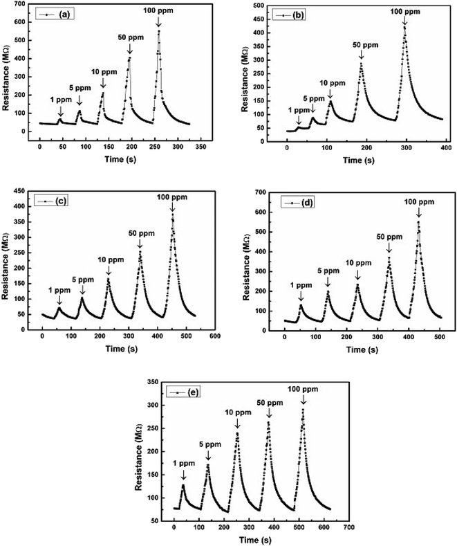 |
| | Fig. 7 (a)–(e) Electrical resistances (MΩ) vs. time (s) plot of a PVA/Y2O3 nanocomposite film sensor at an optimized operating temperature of 100 °C towards different concentrations of CO2 gas: (a) PVA/Y2O3 nanocomposite film with 5 wt% Y2O3 NPs loading, (b) 10 wt% Y2O3 NPs loading, (c) 15 wt% Y2O3 NPs loading, (d) 20 wt% Y2O3 NPs loading, and (e) 25 wt% Y2O3 NPs loading. | |
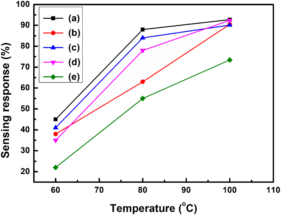
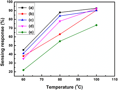
4.3 Effect of Y2O3 NPs loading on the CO2 gas sensing response of the PVA/Y2O3 nanocomposite films
The sensing response properties of the PVA/Y2O3 nanocomposite film-based fabricated chemiresistive sensors were tested inside a test chamber in the presence of CO2 gas, and nitrogen gas was used for purging. To test the CO2 gas sensing performance improvements of the Y2O3 NPs reinforced in non-conducting PVA polymer matrix versions of the PVA/Y2O3 nanocomposite film, several PVA/Y2O3 nanocomposite samples prepared with different Y2O3 NPs wt% filler loading in a PVA matrix were used to fabricate the chemiresistive gas sensors. It is well known that the sensing response of a chemiresistive gas sensor is extremely dependent on the concentration of doping (i.e., wt% of filler loading), as well as the operating temperature of the sensor, as demonstrated in the sensing response plot (Fig. 8a–e). The chemiresistive sensor response of the PVA/Y2O3 nanocomposite films as a function of the working temperature for different wt% of Y2O3 NPs filler loading in the PVA matrix towards 100 ppm of CO2 gas concentration at different working temperatures with the temperature interval of 10 °C is depicted in Fig. 8a–e. The CO2 gas sensing response of the fabricated PVA/Y2O3 nanocomposite film-based chemiresistive sensor with different wt% filler loading of Y2O3 NPs in a non-conducting PVA matrix showed an enhanced sensing response with increasing working temperature from 60 °C to 100 °C, and reached a maximum sensing response value at 100 °C. Hence, the operating temperature of the fabricated sensors is 100 °C. It was observed that further increasing the working temperature above 100 °C for the evaluation of the gas sensing performance of the PVA/Y2O3 nanocomposite film-based chemiresistive sensors presented significant fluctuations and quite strongly reduced gas sensing response. Beyond the operating temperature (i.e., 100 °C) for the PVA/Y2O3 nanocomposite film-based chemiresistive sensors, the sensing response value started to fluctuate and quite strongly decreased, which may be attributed to the desorption of the adsorbed oxygen molecules from the active sensing surface of the Y2O3 NPs reinforced in the PVA matrix. At higher operating temperature (i.e., 100 °C), the increase in the internal thermal vibration of the adsorbed oxygen molecules results in detachment from the active sensing surface of the Y2O3 NPs reinforced in the PVA matrix. According to the TGA analysis, after the addition of different wt% filler loading of Y2O3 NPs in the PVA polymer matrix, the first decomposition step of the PVA/Y2O3 nanocomposite film starts from ∼60 °C to ∼148 °C, which is attributed to the evaporation of absorbed water molecules from the PVA polymer matrix surface. This clearly indicates the dependences of the sensing response on the thermal stability of the PVA/Y2O3 nanocomposite films. However, one disadvantage was found: the entire fabricated PVA/Y2O3 nanocomposite film sensor presented significant fluctuations or a sharply reduced sensing response above the operating temperature of 100 °C. This behaviour presents a major drawback for high temperature gas sensing applications. It can be seen that the 5 wt% filler loading of Y2O3 NPs in the PVA/Y2O3 nanocomposite film shows the maximum sensing response (∼92.72%). However, with increasing wt% filler loading of Y2O3 NPs up to 20 wt% in the PVA/Y2O3 nanocomposite films, a drop in the maximum sensing response (S ∼92.36%) is observed, where further increases in the wt% filler loading of Y2O3 NPs up to 25 wt% in the PVA/Y2O3 nanocomposite films causes a high drop in the maximum sensing response (∼73.44%) at a lower operating temperature (100 °C). However, the sensing response becomes lower with increasing wt% filler loading of Y2O3 NPs in PVA/Y2O3 nanocomposite-based chemiresistive sensors, indicating that the excess incorporation of Y2O3 NPs in the non-conducting PVA polymer matrix can result in a tremendous loss of active surface area due to the wrapping of Y2O3 NPs by the non-conducting PVA polymer. Therefore, the catalytic activity decreased significantly due to the wrapping or agglomeration of Y2O3 NPs in the PVA polymer matrix with the introduction of excess Y2O3 NPs, which results in a relatively weaker interaction between the CO2 gas and Y2O3 NPs. As a result, a drop in the sensing response was observed with increasing wt% filler loading of Y2O3 NPs in the PVA/Y2O3 nanocomposite films compared to the 5 wt% filler loading of Y2O3 NPs in the PVA/Y2O3 nanocomposite film-based chemiresistive sensor. A PVA/Y2O3 nanocomposite film with 5 wt% filler loading of Y2O3 NPs in the non-conducting PVA polymer matrix showed the highest sensing response (S ∼92.72%) at the optimized operating temperature (Topt. = 100 °C) towards 100 ppm of CO2 gas concentration, as shown in Fig. 8a. The CO2 gas sensing performance comparison of the chemiresistive sensor based on the various other sensing materials is summarized in Table 1.
 |
| | Fig. 8 (a)–(e) Variation in the sensing response (%) vs. different operating temperature curves for PVA/Y2O3 nanocomposite film sensors towards 100 ppm of CO2 gas concentrations: (a) PVA/Y2O3 nanocomposite film with 5 wt% Y2O3 NPs loading, (b) 10 wt% Y2O3 NPs loading, (c) 15 wt% Y2O3 NPs loading, (d) 20 wt% Y2O3 NPs loading, and (e) 25 wt% Y2O3 NPs loading. | |
Table 1 A comparison of the CO2 gas sensing performance of the fabricated PVA/Y2O3 nanocomposite film-based chemiresistive sensor with some recently reported sensing materials available in the literaturea
| Sr. No. |
Sensing materials |
Sensitivity (%) |
Topt. (°C) |
Concentration (ppm) |
Gas vapors |
T90/T10 |
Ref. |
| Note: Polyethylenimine (PEI)/Nitrogen-Doped Reduced Graphene Oxide (NrGO)/ZnO Nanorod sensor; Gd0.2La0.2Y0.2Hf0.2Zr0.2O2 (Y-HEC)-based sensor; copper oxide (CuO) with functionalized graphene (rGO) hybrid material-based fabricated QCM (quartz crystal microbalance) sensor; room temperature (RT); Cadmium-doped zinc oxide (Cd-doped ZnO) films sensor; porous silicon/molybdenum trioxide nanohybrid structure (p-Si/MoO3) sensor; response time (T90); recovery time (T10); operating temperature (Topt.) and ppm = parts per million, sensing response (*S). |
| 1 |
MgFe2O4 |
36 |
450 |
5000 |
CO2 |
2 min/4 min |
6 |
| 2 |
Y-HEC sensor |
46.7 |
27 |
10000 |
CO2 |
49 s/200 s |
10 |
| 3 |
CaO–BaTiO3 heterostructures |
65 |
160 |
1000 |
CO2 |
15 s/35 s |
15 |
| 4 |
Yttrium-doped ZnO:CdO nanocomposites |
9 |
27 |
500 |
CO2 |
s/2 s |
18 |
| 5 |
Bismuth oxide (Bi2O3) nanosensors |
179 |
27 |
100 |
CO2 |
132 s/82 s |
22 |
| 6 |
PEI/NrGO/ZnO nanorods |
8.63 |
25 |
50000 |
CO2 |
2 min/30 min |
49 |
| 7 |
CuO/rGO hybrid material-coated QCM sensor |
2.56 Hz ppm−1 |
RT |
50 |
CO2 |
41 s/20 s |
51 |
| 8 |
Cadmium-doped zinc oxide (Cd–ZnO) |
88.24 |
125 |
100 |
CO2 |
19 s/1 s |
52 |
| 9 |
p-Si/MoO3 |
12.08 |
250 |
100 |
CO2 |
8 s/15 s |
53 |
| 10 |
5 wt% PVA/Y2O3 nanocomposite film |
*S = 92.72 |
100 |
100 |
CO2 |
15 s/11 s |
Present work |
4.4 Effect of Y2O3 NPs loading on the active region of the PVA/Y2O3 nanocomposite film
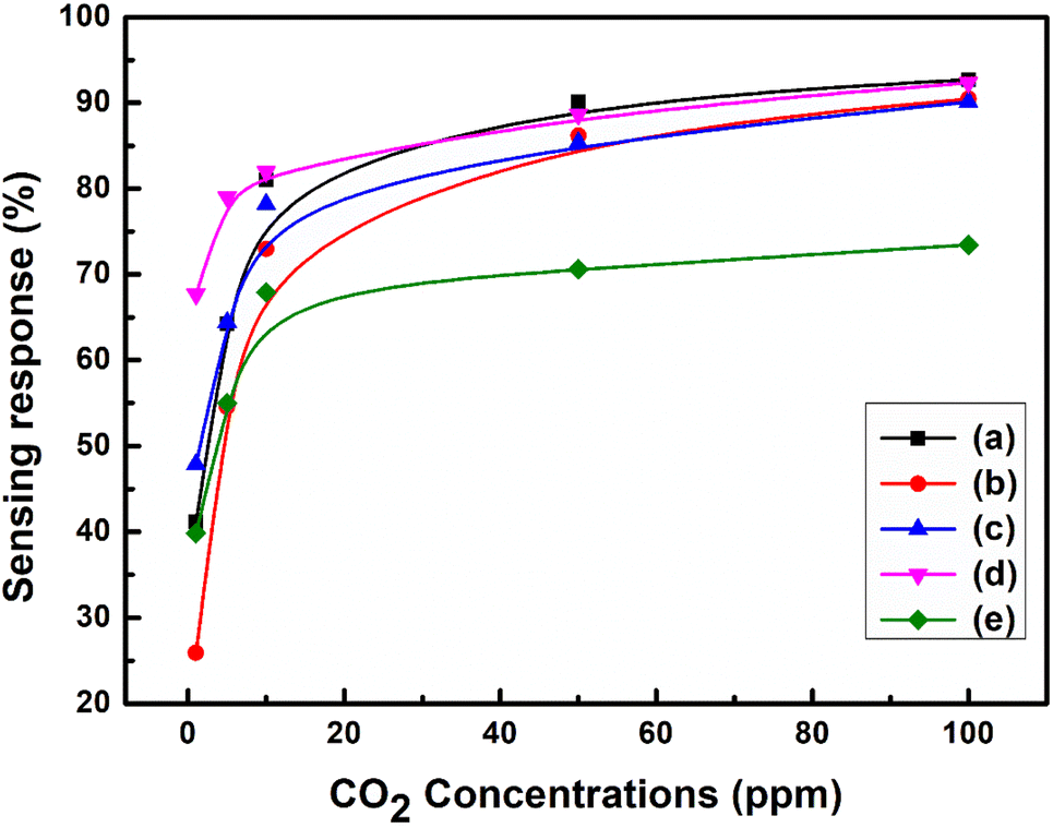
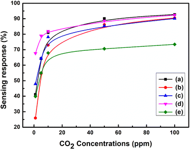
The active region of the PVA/Y2O3 nanocomposite film-based chemiresistive sensors for different gas concentration levels at the optimized operating temperature (100 °C) was analysed. The variation in the sensing response of chemiresistive gas sensors exposed to CO2 gas for different concentration levels from 1 ppm to 100 ppm in air at optimized operating temperatures for the PVA/Y2O3 nanocomposite samples prepared with different wt% filler loading of Y2O3 NPs is depicted in Fig. 9a–e. The PVA/Y2O3 nanocomposite film-based chemiresistive gas sensor exposure to CO2 gas results in a linear increase in the sensing response with an increase in the CO2 gas concentration levels from 1 ppm to 100 ppm. The maximum sensing response was obtained at 100 ppm of CO2 gas, and became saturated at CO2 gas concentrations above 100 ppm. The calibration curve of the PVA/Y2O3 nanocomposite film with 5 wt% filler loading of Y2O3 NPs is shown in Fig. 9a. Among all of the fabricated chemiresistive sensors based on the PVA/Y2O3 nanocomposite films with different wt% filler loading of Y2O3 NPs in the PVA polymer matrix, the PVA/Y2O3 nanocomposite film with 5 wt% filler loading of Y2O3 NPs in the PVA polymer matrix showed a good sensing response (S ∼41.17%) to CO2 gas at lower concentrations up to 1 ppm in air, and relatively high sensing response (S ∼92.72%) at 100 ppm of CO2 gas concentrations. Upon further increasing the CO2 gas concentrations, the sensing response reached a saturation value once the CO2 gas concentration was above 100 ppm. Therefore, the active region of these 5 wt% PVA/Y2O3 nanocomposite film sensors is from 1 ppm to 100 ppm of CO2 gas concentrations.
 |
| | Fig. 9 (a)–(e) Calibration curves of the PVA/Y2O3 nanocomposite film sensor at an optimized operating temperature of 100 °C towards different concentrations of CO2 gas: (a) PVA/Y2O3 nanocomposite film with 5 wt% Y2O3 NPs loading, (b) 10 wt% Y2O3 NPs loading, (c) 15 wt% Y2O3 NPs loading, (d) 20 wt% Y2O3 NPs loading, and (e) 25 wt% Y2O3 NPs loading. | |
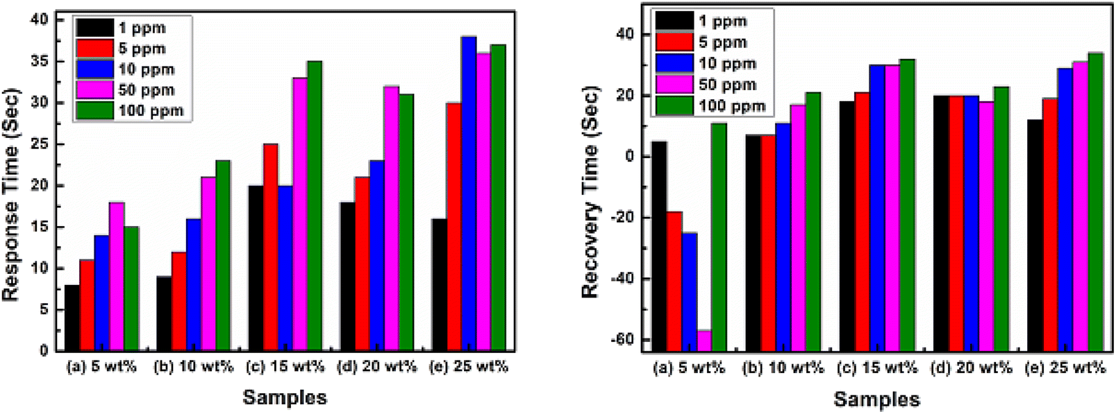
4.5 Effect of the Y2O3 NPs loading on the transient analyses of the PVA/Y2O3 nanocomposite films
Fig. 10 depicts the transient analysis (response/recovery time) behaviour of the different wt% filler loading of Y2O3 NPs in PVA/Y2O3 nanocomposite film-based chemiresistive sensors analysed at 100 ppm of CO2 gas concentration at their optimized operating temperature of 100 °C. The response time (Tres)/recovery time (Trec) of the 5 wt% PVA/Y2O3 nanocomposite film-based chemiresistive sensor for CO2 gas concentration was observed to be 8 s/5 s for 1 ppm, 11 s/18 s for 5 ppm, 14 s/25 s for 10 ppm, 18 s/57 s for 50 ppm, and 15 s/11 s for 100 ppm. The response/recovery time of the 10 wt% PVA/Y2O3 nanocomposite film sensor for CO2 gas concentration was observed to be 9 s/7 s for 1 ppm, 12 s/7 s for 5 ppm, 16 s/11 s for 10 ppm, 21 s/17 s for 50 ppm, and 23 s/21 s for 100 ppm. The response/recovery time of the 15 wt% PVA/Y2O3 nanocomposite film sensor for CO2 gas concentration was observed to be 20 s/18 s for 1 ppm, 25 s/21 s for 5 ppm, 20 s/30 s for 10 ppm, 33 s/30 s for 50 ppm, and 35 s/32 s for 100 ppm. The response/recovery time of the 20 wt% PVA/Y2O3 nanocomposite film sensor for CO2 gas concentration was observed to be 18 s/20 s for 1 ppm, 21 s/20 s for 5 ppm, 23 s/20 s for 10 ppm, 32 s/18 s for 50 ppm, and 31 s/23 s for 100 ppm. The response/recovery time of the 25 wt% PVA/Y2O3 nanocomposite film sensor for CO2 gas concentration was observed to be 16 s/12 s for 1 ppm, 30 s/19 s for 5 ppm, 38 s/29 s for 10 ppm, 36 s/31 s for 50 ppm, and 37 s/34 s for 100 ppm. Among all the fabricated PVA/Y2O3 nanocomposite film-based chemiresistive sensors, the 5 wt% PVA/Y2O3 nanocomposite film sensor showed the fast response/recovery time of 15 s/11 s for the 100 ppm of CO2 gas concentration at the optimized operating temperature of 100 °C.
 |
| | Fig. 10 Transient analysis of PVA/Y2O3 nanocomposite film-based fabricated chemiresistive sensors at 100 °C towards different concentrations of CO2 gas: (a) PVA/Y2O3 nanocomposite film with 5 wt% filler loading of Y2O3 NPs, (b) 10 wt% Y2O3 NPs loading, (c) 15 wt% Y2O3 NPs loading, (d) 20 wt% Y2O3 NPs loading, and (e) 25 wt% Y2O3 NPs loading. | |
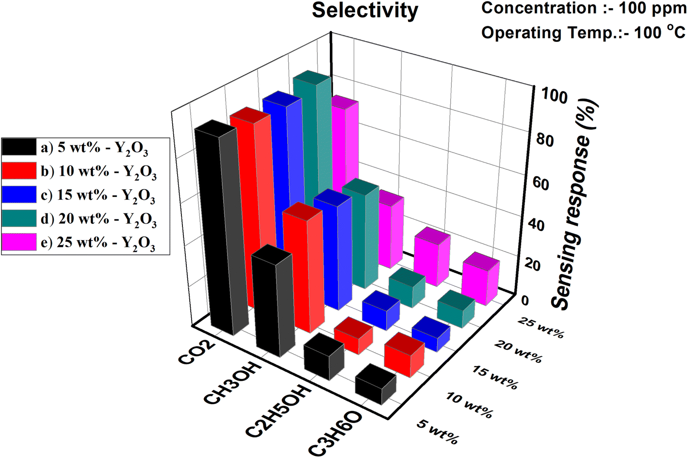
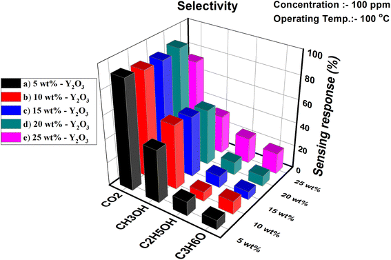
4.6 Effect of Y2O3 NPs loading on the selectivity analyses of the PVA/Y2O3 nanocomposite films
Selectivity is one of the major key issues of chemiresistive sensors for the practical implementation of the sensor in environmental monitoring. Fig. 11 demonstrates the gas sensing response of the PVA/Y2O3 nanocomposite film sensor to different test gases, including carbon dioxide (CO2), methanol (CH3OH), ethanol (C2H5OH), and acetone (C3H6O). The fabricated 5 wt% PVA/Y2O3 nanocomposite film sensor displays a low sensing response towards 100 ppm of different interfering gases as compared to CO2 gas at the optimized operating temperature of 100 °C. This study indicates that the 5 wt% PVA/Y2O3 nanocomposite film sensor device is highly selective towards the target CO2 gas.
 |
| | Fig. 11 Selectivity analyses of the PVA/Y2O3 nanocomposite film-based chemiresistive sensor exposed to different gases at the optimized operating temperature of 100 °C: (a) PVA/Y2O3 nanocomposite film with 5 wt% filler loading of Y2O3 NPs, (b) 10 wt% Y2O3 NPs loading, (c) 15 wt% Y2O3 NPs loading, (d) 20 wt% Y2O3 NPs loading, and (e) 25 wt% Y2O3 NPs loading. | |
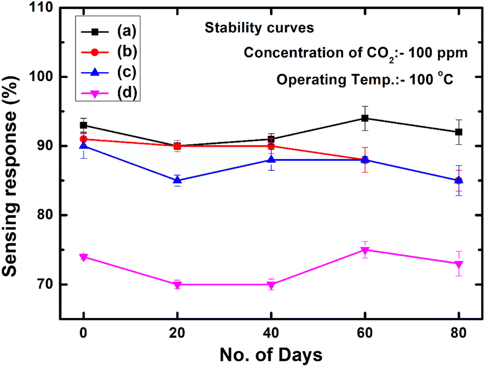
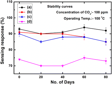
4.7 Effect of Y2O3 NPs loading on the long-term stability analyses of the PVA/Y2O3 nanocomposite films
The long-term stability of the PVA/Y2O3 nanocomposite film-based chemiresistive sensor plays a vital role for monitoring the CO2 gas sensing performance. The intention of this work is to design and develop a Y2O3 NPs-reinforced PVA polymer-based chemiresistive sensor with the goal of identifying the effects of the Y2O3 NPs wt% filler loading in the non-conducting PVA polymer matrix since the effect of the wt% filler loading, surface related properties and different surface morphologies can demonstrate various sensing performances. Herein, we focus our attention on the Y2O3 NPs wt% filler loading and the change in the surface morphology of the PVA/Y2O3 nanocomposite materials, as these phenomena are responsible for the significant change in the gas sensing performance. Therefore, it is necessary to understand the effect of the wt% loading and surface morphologies of non-conducting PVA polymer-based gas sensing materials to improve the gas sensing performance. Finally, the low-temperature (100 °C) monitoring of the CO2 gas sensing performance of the Y2O3 NPs with different wt% filler loading was measured, and is depicted in Fig. 12. In the present work, the stability of the PVA/Y2O3 nanocomposite film was significantly improved with reinforcing Y2O3 NPs in the non-conducting PVA polymer matrix. This is because the lower filler loading of Y2O3 NPs (i.e., 5 wt%) in the PVA polymer matrix could prevent the aggregation of Y2O3 NPs during the reaction and get deposited on the surface of the PVA polymer, which demonstrated that the Y2O3 NPs have the predominant active sites for the CO2 reaction on the PVA/Y2O3 nanocomposite film surface with remarkably improved long-term stability. However, the long-term stability of the PVA/Y2O3 nanocomposite film becomes lower with increasing Y2O3 NPs wt% filler loading in the PVA matrix, indicating that the excess reinforcing of Y2O3 NPs in the PVA matrix can result in a tremendous loss of active surface area due to the wrapping of Y2O3 NPs by the non-conducting PVA polymer. Therefore, the catalytic activity decreased significantly due to the agglomeration of Y2O3 NPs in the PVA polymer matrix with the excess reinforcing of Y2O3 NPs, resulting in a relatively weaker interaction between Y2O3 NPs and CO2 gas. Thus, the lower long-term stability of the PVA/Y2O3 nanocomposite film could be attributed to the increasing amount of Y2O3 NPs wt% filler loading in the PVA polymer matrix as compared to the 5 wt% Y2O3 NPs filler loading in the PVA/Y2O3 nanocomposite film.
 |
| | Fig. 12 Long-term stability of chemiresistive sensors based on the PVA/Y2O3 nanocomposite film for the detection of 100 ppm CO2 gas concentration at 100 °C: (a) PVA/Y2O3 nanocomposite film with 5 wt% filler loading of Y2O3 NPs, (b) 10 wt% Y2O3 NPs loading, (c) 15 wt% Y2O3 NPs loading, and (d) 25 wt% Y2O3 NPs loading. | |
4.8 Effect of the Y2O3 NPs loading on the repeatability analyses of the PVA/Y2O3 nanocomposite films
Fig. 13 depicts the repeatability plot for the PVA/Y2O3 nanocomposite film with different wt% filler loading of Y2O3 NPs in the PVA polymer matrix. The multi-cycle dynamic gas sensing response of the PVA/Y2O3 nanocomposite film with different wt% filler loading of the Y2O3 NPs-based chemiresistive sensor was tested towards 100 ppm of CO2 gas concentrations at the optimized operating temperature (100 °C). To better understand the gas sensing performance of the chemiresistive sensor for repeated measurements over time, the response was also studied even after 60 days of the fabrication of the sensor. Among all of the fabricated sensors, the 5 wt% PVA/Y2O3 nanocomposite film-based chemiresistive sensor possesses a relatively higher repeatability even after 60 days of fabrication for the detection of 100 ppm CO2 gas concentrations at 100 °C.
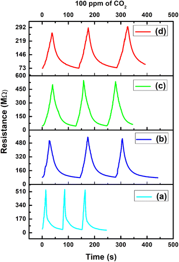 |
| | Fig. 13 Repeatability analyses of the PVA/Y2O3 nanocomposite film-based chemiresistive sensors exposed to 100 ppm CO2 gas concentration at the fixed operating temperature of 100 °C: (a) PVA/Y2O3 nanocomposite film with 5 wt% filler loading of Y2O3 NPs, (b) 10 wt% Y2O3 NPs loading, (c) 15 wt% Y2O3 NPs loading, and (d) 25 wt% Y2O3 NPs loading. | |
5 Conclusions
In the current research, PVA/Y2O3 nanocomposite films with different wt% of Y2O3 NPs were successfully synthesized via solution casting approach. The physico-chemical properties of the as-prepared PVA/Y2O3 nanocomposite films with different wt% of Y2O3 NPs (5, 10, 15, 20 and 25 wt%) were analysed using FTIR, XRD and SEM. The results exhibited the good dispersion of the Y2O3 NPs in the PVA matrix and intermolecular interaction between the Y2O3 NPs and PVA matrix. The thermal properties of the pure PVA and PVA/Y2O3 nanocomposite films were investigated using TGA, and results show that the thermal stability and residual production increased with increasing Y2O3 NPs. Furthermore, the effect of different wt% filler loading of Y2O3 NPs on the structure, surface morphology, electrical and gas sensing properties of the PVA/Y2O3 nanocomposite films was investigated. The results confirm that the PVA/Y2O3 nanocomposite films are a viable chemiresistive sensor for the sensitive and selective detection of carbon dioxide (CO2) gas. These experimental results suggest that optimizing the wt% filler loading of Y2O3 NPs in the non-conducting PVA polymer matrix is important to detecting the target CO2 gas with an improved sensing response. The PVA/Y2O3 nanocomposite film with 5 wt% Y2O3 NPs filler loading showed improved figures of merit (i.e., sensing response, selectivity, response/recovery time, long-term stability, repeatability etc.) among all the other PVA/Y2O3 nanocomposite film-based flexible chemiresistive sensors. However, the sensing behaviour of the PVA/Y2O3 nanocomposite film declined upon the higher filler loading of Y2O3 NPs in the PVA polymer matrix, which might be due to the wrapping of Y2O3 NPs by the non-conducting PVA polymer or may be due to the filler concentration being above the percolation limit. The results obtained primarily for the PVA/Y2O3 nanocomposite film-based chemiresistive sensors suggest that among all the fabricated sensors, the specimen containing 5 wt% Y2O3 NPs filler loading in PVA polymer matrix can be ideally suited for the development of a flexible chemiresistive sensor due to its high sensing response (S ∼92.72%), fast response time (15 s)/recovery time (11 s), excellent selectivity to CO2 over other gases, and good long-term stability of 80 days for the detection of CO2 gas at a relatively low operating temperature of 100 °C for environmental monitoring and industrial process control applications.
Conflicts of interest
The authors declare that they have no known competing financial interests or personal relationships that could have appeared to influence the work reported in this paper.
References
- J. C. Bittencourt, B. H. de Santana Gois, V. J. Rodrigues de Oliveira, D. L. da Silva Agostini and C. de Almeida Olivati, J. Appl. Polym. Sci., 2019, 136, 47288 CrossRef.
- J. G. Thangamani, K. Deshmukh, K. Kumar Sadasivuni, K. Chidambaram, M. Basheer Ahamed, D. Ponnamma, M. Al-Ali AlMaadeed and S. K. Khadheer Pasha, Adv. Mater. Lett., 2017, 8, 196–205 CrossRef.
- G. J. Thangamani, K. Deshmukh, T. Kovářík, N. A. Nambiraj, D. Ponnamma, K. K. Sadasivuni, H. A. Khalil and S. K. Pasha, Chemosphere, 2021, 280, 130641 CrossRef CAS PubMed.
- Y. R. Kumar, K. Deshmukh, K. K. Sadasivuni and S. K. Pasha, RSC Adv., 2020, 10, 23861–23898 RSC.
- Y. R. Kumar, K. Deshmukh, T. Kovářík and S. K. Pasha, Coord. Chem. Rev., 2022, 461, 214502 CrossRef.
- T. P. Sumangala, I. Pasquet, L. Presmanes, Y. Thimont, C. Bonningue, N. Venkataramani, S. Prasad, V. Baco-Carles, P. Tailhades and A. Barnabé, Ceram. Int., 2018, 44, 18578–18584 CrossRef.
- J. Devkota, K. J. Kim, P. R. Ohodnicki, J. T. Culp, D. W. Greve and J. W. Lekse, Nanoscale, 2018, 10, 8075–8087 RSC.
- K. R. Nemade and S. A. Waghuley, Int. J. Mod. Phys. Conf., 2013, 22, 380–384 CrossRef CAS.
- H. Kawahata, K. Fujita, A. Iguchi, M. Inoue, S. Iwasaki, A. Kuroyanagi, A. Maeda, T. Manaka, K. Moriya, H. Takagi and T. Toyofuku, Prog. Earth Planet. Sci., 2019, 6, 1–37 CrossRef.
- V. R. Naganaboina, M. Anandkumar, A. S. Deshpande and S. G. Singh, ACS Appl. Nano Mater., 2022, 5, 4524–4536 CrossRef CAS.
- T. Eggleton, A Short Introduction to Climate Change, Cambridge University Press, 2021, p. 52 Search PubMed.
- UN News – Climate and Environment, 2022 Search PubMed.
- S. Bag and K. Pal, Sens. Actuators, B, 2020, 303, 127115 CrossRef CAS.
- S. Joshi, S. Lanka, S. J. Ippolito, S. K. Bhargava and M. V. Sunkara, J. Mater. Chem. A, 2016, 4, 16418–16431 RSC.
- S. Joshi, F. Antolasic, M. V. Sunkara, S. K. Bhargava and S. J. Ippolito, ACS Sustain. Chem. Eng., 2018, 6, 4086–4097 CrossRef CAS.
- A. Gheorghe, O. Lugier, B. Ye and S. Tanase, J. Mater. Chem. C, 2021, 9, 16132–16142 RSC.
- A. Hannon and J. Li, Sensors, 2019, 19, 3848 CrossRef CAS PubMed.
- K. Choudhary, R. Saini, G. K. Upadhyay and L. P. Purohit, J. Alloys Compd., 2021, 879, 160479 CrossRef CAS.
- S. Maheswari, M. Karunakaran, K. Kasirajan, L. B. Chandrasekar and P. Boomi, Sens. Actuators, A, 2020, 315, 112303 CrossRef CAS.
- A. Yamamoto, T. Shinkai, A. C. M. Loy, M. Mohamed, F. H. B. Baldovino, S. Yusup, A. T. Quitain and T. Kida, Sens. Actuators, B, 2020, 315, 128105 CrossRef CAS.
- H. Abdali, B. Heli and A. Ajji, Sensors, 2019, 19, 5215 CrossRef CAS PubMed.
- P. V. Shinde, N. M. Shinde, S. F. Shaikh, D. Lee, J. M. Yun, L. J. Woo, A. M. Al-Enizi, R. S. Mane and K. H. Kim, RSC Adv., 2020, 10, 17217–17227 RSC.
- G. J. Thangamani and S. K. Pasha, Chemosphere, 2021, 277, 130237 CrossRef PubMed.
- G. J. Thangamani, K. Deshmukh, N. A. Nambiraj and S. K. Pasha, Synth. Met., 2021, 273, 116687 CrossRef CAS.
- G. J. Thangamani and S. K. Pasha, Chemosphere, 2021, 275, 129960 CrossRef CAS PubMed.
- G. J. Thangamani, K. Deshmukh, K. Chidambaram, M. B. Ahamed, K. K. Sadasivuni, D. Ponnamma, N. Faisal, N. A. Nambiraj and S. K. K. Pasha, J. Mater. Sci.: Mater. Electron., 2018, 29, 5186–5205 CrossRef CAS.
- C. Chavan, R. F. Bhajantri, S. Bulla, H. B. Ravikumar, M. Raghavendra, K. Sakthipandi, K. Y. Kumar and B. P. Prasanna, Ceram. Int., 2022, 48, 17864–17884 CrossRef CAS.
- N. Afsharimani and B. Nysten, Bull. Mater. Sci., 2019, 42, 1–9 CrossRef CAS.
- S. K. Pasha, K. Deshmukh, M. B. Ahamed, K. Chidambaram, M. K. Mohanapriya and N. A. N. Raj, Adv. Polym. Technol., 2017, 36, 352–361 CrossRef CAS.
- M. A. Habeeb, Mater. Focus, 2016, 5, 550–555 CrossRef CAS.
- Z. M. Larimi, A. Amirabadizadeh and A. Zelati, In Proceedings of the International Conference on Chemistry and Chemical Process IPCBEE, IACSIT Press, Singapore, 2011, pp. 86–90 Search PubMed.
- J. Zheng, T. Zhang, H. Zeng, W. Guo, B. Zhao, Y. Sun, Y. Li and L. Jiang, Small, 2019, 15, 1804688 CrossRef PubMed.
- R. Lozano-Rosas, D. G. Lamas, F. Sánchez-Ochoa, G. H. Cocoletzi, T. V. K. Karthik and M. J. Robles-Águila, Appl. Phys. A: Mater. Sci. Process., 2021, 127, 1–14 CrossRef.
- Y. R. Kumar, K. Deshmukh, M. N. N. Ali, G. Abhijay, W. A. Al-Onazi, A. M. Al-Mohaimeed and S. K. Pasha, Environ. Res., 2022, 203, 111842 CrossRef CAS PubMed.
- Y. R. Kumar and S. K. Pasha, Polym. Plast. Technol. Mater., 2022, 61, 1857–1870 CAS.
- Z. A. Alrowaili, T. A. Taha, K. S. El-Nasser and H. Donya, J. Inorg. Organomet. Polym. Mater., 2021, 31, 3101–3110 CrossRef CAS.
- M. K. Mohanapriya, K. Deshmukh, K. Chidambaram, M. B. Ahamed, K. K. Sadasivuni, D. Ponnamma, M. A. A. AlMaadeed, R. R. Deshmukh and S. K. Pasha, J. Mater. Sci. Mater. Electron., 2017, 28, 6099–6111 CrossRef CAS.
- T. A. Taha, S. Elrabaie and M. T. Attia, J. Electron. Mater., 2019, 48, 6797–6806 CrossRef CAS.
- K. Jayasankar, A. Pandey, B. K. Mishra and S. Das, Mater. Chem. Phys., 2016, 171, 195–200 CrossRef CAS.
- K. Deshmukh, M. B. Ahamed, R. R. Deshmukh, P. R. Bhagat, S. K. Pasha, A. Bhagat, R. Shirbhate, F. Telare and C. Lakhani, Polym. Plast. Technol. Eng., 2016, 55, 231–241 CrossRef CAS.
- J. Y. Jeong, S. W. Park, D. K. Moon and W. J. Kim, J. Ind. Eng. Chem., 2010, 16, 243–250 CrossRef CAS.
- G. Dong, Y. Chi, X. Xiao, X. Liu, B. Qian, Z. Ma, E. Wu, H. Zeng, D. Chen and J. Qiu, Opt. Express, 2009, 17, 22514–22519 CrossRef CAS PubMed.
- Y. Sha, T. Dong, Q. Zhao, H. Zheng, X. Wen, S. Chen and S. Zhang, Ionics, 2020, 26, 4803–4812 CrossRef CAS.
- M. M. Gomaa, C. Hugenschmidt, M. Dickmann, E. E. Abdel-Hady, H. F. Mohamed and M. O. Abdel-Hamed, Phys. Chem. Chem. Phys., 2018, 20, 28287–28299 RSC.
- G. J. Thangamani, K. Deshmukh, K. K. Sadasivuni, D. Ponnamma, S. Goutham, K. Venkateswara Rao, K. Chidambaram, M. Basheer Ahamed, A. Nirmala Grace, M. Faisal and S. K. K. Pasha, Microchim. Acta, 2017, 184, 3977–3987 CrossRef.
- P. L. Reddy, K. Deshmukh, K. Chidambaram, M. M. N. Ali, K. K. Sadasivuni, Y. R. Kumar, R. Lakshmipathy and S. K. Pasha, J. Mater. Sci.: Mater. Electron., 2019, 30, 4676–4687 CrossRef CAS.
- C. Merlini, G. M. O. Barra, T. M. Araujo and A. Pegoretti, RSC Adv., 2014, 4, 15749–15758 RSC.
- W. Li, H. Li and Y. M. Zhang, J. Mater. Sci., 2009, 44, 2977–2984 CrossRef CAS.
- M. S. Abadi, M. N. Hamidon, A. H. Shaari, N. Abdullah, N. Misron and R. Wagiran, Sensors, 2010, 10, 5074 CrossRef CAS PubMed.
- A. R. Tripathy, C. Chang, S. Gupta, A. K. Anbalagan, C. H. Lee, S. S. Li and N. H. Tai, ACS Appl. Nano Mater., 2022, 5, 6543–6554 CrossRef CAS.
- M. Gupta, H. F. Hawari, P. Kumar and Z. A. Burhanudin, Crystals, 2022, 12, 264 CrossRef CAS.
- B. Altun, I. Karaduman Er, A. O. Çağırtekin, A. Ajjaq, F. Sarf and S. Acar, Appl. Phys. A, 2021, 127, 687 CrossRef CAS.
- T. Thomas, Y. Kumar, J. A. R. Ramón, V. Agarwal, S. S. Guzmán, R. Reshmi, S. Pushpan, S. L. Loredo and K. C. Sanal, Vacuum, 2021, 184, 109983 CrossRef CAS.
|
| This journal is © The Royal Society of Chemistry 2024 |
Click here to see how this site uses Cookies. View our privacy policy here. 
 Open Access Article
 This Open Access Article is licensed under a Creative Commons Attribution-Non Commercial 3.0 Unported Licence
 *a
*a