Improving energy storage properties of PbHfO3-based antiferroelectric ceramics with lower phase transition fields†
Yan
Li
 ,
Tongqing
Yang
* and
Xiaohui
Liu

Key Laboratory of Advanced Civil Engineering Materials of the Ministry of Education, Functional Materials Research Laboratory, School of Materials Science and Engineering, Tongji University, 4800 Cao'an Road, Shanghai, 201804, China. E-mail: Yangtongqing@tongji.edu.cn
First published on 7th November 2023
Abstract
Dielectric energy storage devices are commonly used in applications involving high voltage levels. However, the presence of inherent risks and the costly insulation technology associated with these high voltages have emphasized the importance of improving energy storage density at lower electric fields. To achieve a high energy storage density at lower electric fields for antiferroelectric materials, it is necessary to decrease their antiferroelectric to ferroelectric phase transition electric fields (EAFE–FE) and acquire double hysteresis loops at lower electric fields. In this study, antiferroelectric ceramics were synthesized, specifically (Pb0.97La0.02)(HfxSn0.95−xTi0.05)O3 (PLHST), using the tape-casting method. An important observation is that increasing the Hf4+ content in PLHST ceramics can effectively reduce the antiferroelectric to ferroelectric phase transition electric field, resulting in a significant increase in maximum polarization (Pmax) and consequently leading to higher energy storage density. As a result, the (Pb0.97La0.02)(Hf0.6Sn0.35Ti0.05)O3 antiferroelectric ceramic with a lower antiferroelectric to ferroelectric phase transition electric field of 15.4 kV mm−1 can simultaneously exhibit an excellent recoverable energy storage density (Wrec) of 6.9 J cm−3 and a high energy efficiency (η) of 87.8%. Moreover, we introduce a merit value denoted as Wrec/EAFE–FE for further evaluation. A high Wrec/EAFE–FE value means that a material can achieve a large energy density under lower antiferroelectric to ferroelectric phase transition electric fields. Furthermore, charge–discharge tests indicate that this ceramic also demonstrates a superior discharge energy density (Wdis) of 5.3 J cm−3 and a large power density (PD) of 149.8 MW cm−3. Additionally, both the recoverable energy storage density and energy efficiency exhibit outstanding frequency stability (1–100 Hz) and strong fatigue endurance (10![[thin space (1/6-em)]](https://www.rsc.org/images/entities/char_2009.gif) 000 cycles). These above results collectively demonstrate that this work offers a promising antiferroelectric material for pulsed power applications at lower applied electric fields.
000 cycles). These above results collectively demonstrate that this work offers a promising antiferroelectric material for pulsed power applications at lower applied electric fields.
1. Introduction
With the growing concern over advanced electronic devices, energy storage technology has garnered widespread attention.1–3 In order to meet the requirements of various applications in commercial, civil, and military systems, such as electronic components and hybrid vehicles, it is necessary to enhance the energy and power densities of electronic devices.4–7 In recent years, there have been significant advancements in dielectric capacitors, attributed to their remarkable ability of ultra-fast charge/discharge and high power density compared to batteries and electrochemical capacitors.8–12 However, their practical applications are limited by their inferior energy density.13,14 Thus, further research is urgently needed to enhance the energy density of dielectric capacitors to meet the demands of various applications.15–18 It is widely understood that the properties of dielectric capacitors are primarily determined by the dielectric materials.19–23 Currently, dielectric energy storage materials mainly include relaxor ferroelectric (RFE) and antiferroelectric (AFE) materials based on nonlinear dielectric materials.24 Particularly, AFE materials occupy a prominent position in the field of energy storage due to their unique AFE to ferroelectric (FE) phase transition, which results in high maximum polarization (Pmax) and almost zero remnant polarization (Pr), making them more suitable for commercial applications.25–29 For AFE materials, the total energy density (Wtot), recoverable energy density (Wrec) and energy efficiency (η) can be calculated using the following formulas:30,31 | (1) |
 | (2) |
 | (3) |
Previous studies have focused on enhancing the energy storage performance of PbZrO3 (PZ) AFE ceramics through ion doping and improving fabrication techniques, enabling their application in capacitors. For example, Wang et al. prepared the (Pb0.98La0.02)(Zr0.55Sn0.45)0.995O3 AFE ceramic using a special rolling process. Under an AFE–FE phase transition electric field of 32 kV mm−1, they achieved a high Wrec of 10.4 J cm−3 and a large η of 87%.32 Meng et al. investigated the influence of the Zr/Sn ratio on the energy storage performance of La-doped PZ-based AFE ceramics. The (Pb0.94La0.04)(Zr0.49Sn0.5Ti0.01)O3 AFE ceramic demonstrated a Wrec of 9.6 J cm−3 under an AFE–FE phase transition electric field of 26.5 kV mm−1.33 The energy storage density of PZ-based AFE ceramics is enhanced by increasing the AFE–FE phase transition electric field, consequently raising the operating voltage of dielectric energy storage devices. However, this approach also comes with increased risks and costs. Differently, Jiang et al. fabricated (Pb0.87Ba0.1La0.02)(ZrxSn0.95−xTi0.05)O3 AFE ceramics using the conventional solid-state reaction process. They achieved a Wrec of 1.4 J cm−3 with an η of 68.5% under an AFE–FE phase transition electric field of 5 kV mm−1.34 Xu et al. designed and prepared the Pb0.97La0.02(Zr0.50Sn0.43Ti0.07)O3 AFE ceramic, achieving a Wrec of 3.47 J cm−3 under an AFE–FE phase transition electric field of 12.5 kV mm−1.35 Although a low AFE–FE phase transition electric field has been achieved in PZ-based AFE materials, they suffer from lower energy storage density.
PbHfO3 (PH) is an emerging antiferroelectric material, serving as another lead-based AFE counterpart with a structure similar to that of PbZrO3 (PZ).36,37 The theoretical prediction that PH materials could exhibit antiferroelectric properties dates back to 1953 when Shirane and Pepinsky first proposed it.38 Wei et al. synthesized pure PH AFE ceramics for the first time, achieving a Wrec of 7.6 J cm−3 under an AFE–FE phase transition electric field of 24 kV mm−1.39 Ge et al. obtained a Wrec of 10.2 J cm−3 under an enhanced AFE–FE phase transition electric field of 26 kV mm−1 by adjusting the Hf/Sn ratio.40 Xu et al. prepared La-doped PH-based AFE ceramics, obtaining a Wrec of 7.1 J cm−3 and an η of 78.5% in Pb0.97La0.02HfO3 under an AFE–FE phase transition electric field of about 26.5 kV mm−1.41 At present, the number of studies on the energy storage performance of PH-based AFE materials is limited. From the above examples, it can be observed that the energy storage performance is predominantly enhanced by increasing the AFE–FE phase transition electric field of PH-based AFE materials, which also increases the inherent risk of high voltage and the cost of insulation technology.
To address the risks associated with dielectric energy storage devices in high-voltage applications and the high costs of insulation technology, we propose an effective strategy for preparing antiferroelectric (AFE) ceramics with lower AFE–FE phase transition electric fields and high energy storage densities. The design strategy of this work is shown in Fig. 1. In this work, (Pb0.97La0.02)(HfxSn0.95−xTi0.05)O3, denoted as PLHST, AFE ceramics were prepared using the tape-casting method. This method allows the production of dense ceramics and has been confirmed by previous studies.3,6,42,43 The influences of Hf4+ content on the microstructure, phase structure, and dielectric and energy storage behavior were investigated in detail. The XRD result indicates that all the compositions exhibit a pure perovskite structure. Moreover, by increasing the Hf4+ content, the Pmax of the prepared ceramics is significantly enhanced. Meanwhile, the AFE–FE phase transition gradually decreases with increasing Hf4+ content, which is favourable for obtaining double hysteresis loops at lower electric fields. It is exciting to find that the PLHST ceramic with x = 0.6 exhibits an excellent Wrec of 6.9 J cm−3 and a high η of 87.8% under a lower AFE–FE phase transition electric field of 15.4 kV mm−1. Furthermore, the pulsed discharge properties were carefully evaluated, resulting in a high discharge energy density (Wdis) of 5.3 J cm−3 and a large power density (PD) of 149.8 MW cm−3. Moreover, the PLHST ceramic with x = 0.6 shows outstanding energy storage stability in 10![[thin space (1/6-em)]](https://www.rsc.org/images/entities/char_2009.gif) 000 cycles and within the frequency range of 1–100 Hz. Based on the above findings, the (Pb0.97La0.02)(Hf0.6Sn0.35Ti0.05)O3 AFE ceramic emerges as a promising candidate for pulsed power capacitors, with the potential to broaden the scope of PbHfO3-based energy storage materials.
000 cycles and within the frequency range of 1–100 Hz. Based on the above findings, the (Pb0.97La0.02)(Hf0.6Sn0.35Ti0.05)O3 AFE ceramic emerges as a promising candidate for pulsed power capacitors, with the potential to broaden the scope of PbHfO3-based energy storage materials.
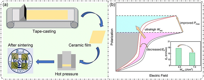 | ||
| Fig. 1 (a) Schematic diagram of the ceramic preparation process and (b) achieving a high Wrec under lower phase transition electric fields. | ||
2. Experimental section
(Pb0.97La0.02)(HfxSn0.95−xTi0.05)O3 (x = 0.4, 0.5, 0.6, and 0.7) ceramics were fabricated using the tape-casting method. The starting materials, including Pb3O4 (≥95%), La2O3 (≥99.9%), HfO2 (≥99.9%), SnO2 (≥99.5%), and TiO2 (≥98%), were weighed based on their chemical formula. An excess of Pb3O4 (5 wt%) was added to compensate for lead volatilization at high temperatures. The mixtures were ball-milled in ethanol using a planetary mill for 24 hours and then sintered at 880 °C for 2 hours to form the main crystal phase of the perovskite structure. The calcined powders were re-mixed for an additional 12 hours to obtain the final PLHST powders. Detailed information regarding the manufacturing process of ceramic tape preparation can be found in the ESI.† Finally, the samples were heated at 550 °C for 8 hours to remove organics and sintered at 1200 °C for 3 hours. The sintered samples were sprayed with gold electrodes to measure high electric fields with a dimension of 2 mm diameter.The phase structure of the ceramics was analyzed using an X-ray diffractometer (XRD Bruker D8 Advanced Diffractometer, Germany). The surface microstructure of the sintered ceramics was examined using scanning electron microscopy (SEM, EMP-800, Tokyo, Japan). A ferroelectric test system (Premier II, Radiant Technologies Inc., USA) was utilized to measure the polarization–electric field (P–E) hysteresis loops and polarization current–electric field (I–E) loops. The temperature-dependent dielectric properties were measured using a computer-controlled LCR meter (HP 4284; Hewlett Packard Co., USA). The charge–discharge properties were measured using a specially designed RLC load circuit.44
3. Results and discussion
The XRD patterns of (Pb0.97La0.02)(HfxSn0.95−xTi0.05)O3 ceramics at room temperature are shown in Fig. 2a, covering the 2θ range of 20–70°. It can be observed that all compositions exhibit an obvious perovskite phase without the coexistence of a secondary phase, indicating that Sn4+ has been successfully diffused into the lattice of PbHfO3.45 The enlarged diffraction peaks with the 2θ range from 43.3 to 45.5° are shown in Fig. 2b. The appearance of (200) and (002) indicates that all ceramics exhibit an orthorhombic phase structure.39,41 Moreover, the diffraction peaks shift towards lower angles as the Hf4+ content increases, which can be explained by the fact that the ionic radius of Hf4+ (0.71 Å) is larger than that of Sn4+ (0.69 Å), resulting in an expansion of the unit cell volume.46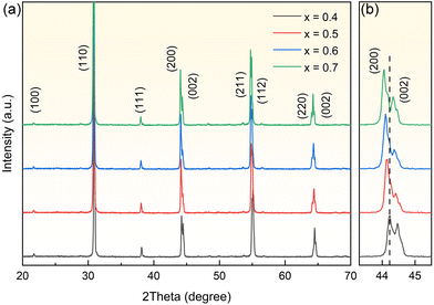 | ||
| Fig. 2 (a) XRD patterns of PLHST AFE ceramics with different Hf4+ contents. (b) (200) and (002) diffraction peaks. | ||
Fig. 3a–d show the surface morphology of (Pb0.97La0.02)(HfxSn0.95−xTi0.05)O3 ceramics. As can be seen, all the samples show a dense microstructure with almost no pores, which is conducive to high BDS. In order to further investigate the grain size variation of PLHST ceramics, Nano Measure software was used to analyze the grain size distributions for different Hf4+ contents. Apparently, the grain size is affected by increasing Hf4+ content, with average grain sizes of 1.90, 2.57, 3.25, and 5.25 μm, respectively, exhibiting an increasing trend. According to previous reports, the grain growth usually depends on the grain boundary mobility.47–49 In this work, the sintering properties improve with increasing Hf4+ content, resulting in enhanced grain boundary mobility during sintering, which promotes grain growth. To confirm the uniformity of the elemental distribution in the PLHST ceramic with x = 0.6, energy-dispersive spectroscopy (EDS) analysis was performed, as shown in Fig. 3e. It is evident that all elements (Pb, Hf, Sn, Ti, and La) are evenly distributed throughout the sample.
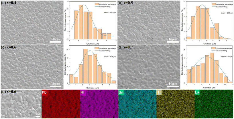 | ||
| Fig. 3 SEM microstructure images and grain size distributions of PLHST ceramics with (a) x = 0.4, (b) x = 0.5, (c) x = 0.6, and (d) x = 0.7. (e) EDX mapping images of the PLHST ceramic with x = 0.6. | ||
The dielectric constant (εr) and dielectric loss (tan![[thin space (1/6-em)]](https://www.rsc.org/images/entities/char_2009.gif) δ) as functions of frequency (1–600 kHz) are presented in Fig. 4a for PLHST ceramics with varying Hf4+ contents, measured at room temperature. As observed, the dielectric constant and dielectric loss remain nearly constant for all ceramics, and the dielectric loss is lower than 0.035 over the measured frequency range. With increasing Hf4+ content, the dielectric constants gradually increase. For instance, as x increases from 0.4 to 0.7, the dielectric constants at 100 kHz are 423, 458, 499 and 507, respectively. Fig. 4b shows the temperature-dependent dielectric constant and dielectric loss of PLHST ceramics ranging from 25 to 375 °C at 10 kHz, and the summarized phase diagram is presented in Fig. 4c. For all compositions, the dielectric constants change gently over a wide temperature range, which originates from the multicell cubic (MCC) state. This state is attributed to the thermodynamic instability of PbSnO3 solid solution, causing disruption of AFE–PE phase transition.47 As can be seen, the ceramics undergo a phase transition from the AFE state to the MCC state and finally to the paraelectric (PE) state as the temperature increases. The MCC–PE phase transition temperature shifts towards a lower temperature as the Hf4+ content increases. In contrast, the AFE–MCC phase transition temperature exhibits an opposite tendency, leading to shrinkage of the MCC region. Furthermore, the dielectric loss of PLHST ceramics is less than 1% within the temperature range of 25–375 °C, which contributes to achieving high energy storage properties.16
δ) as functions of frequency (1–600 kHz) are presented in Fig. 4a for PLHST ceramics with varying Hf4+ contents, measured at room temperature. As observed, the dielectric constant and dielectric loss remain nearly constant for all ceramics, and the dielectric loss is lower than 0.035 over the measured frequency range. With increasing Hf4+ content, the dielectric constants gradually increase. For instance, as x increases from 0.4 to 0.7, the dielectric constants at 100 kHz are 423, 458, 499 and 507, respectively. Fig. 4b shows the temperature-dependent dielectric constant and dielectric loss of PLHST ceramics ranging from 25 to 375 °C at 10 kHz, and the summarized phase diagram is presented in Fig. 4c. For all compositions, the dielectric constants change gently over a wide temperature range, which originates from the multicell cubic (MCC) state. This state is attributed to the thermodynamic instability of PbSnO3 solid solution, causing disruption of AFE–PE phase transition.47 As can be seen, the ceramics undergo a phase transition from the AFE state to the MCC state and finally to the paraelectric (PE) state as the temperature increases. The MCC–PE phase transition temperature shifts towards a lower temperature as the Hf4+ content increases. In contrast, the AFE–MCC phase transition temperature exhibits an opposite tendency, leading to shrinkage of the MCC region. Furthermore, the dielectric loss of PLHST ceramics is less than 1% within the temperature range of 25–375 °C, which contributes to achieving high energy storage properties.16
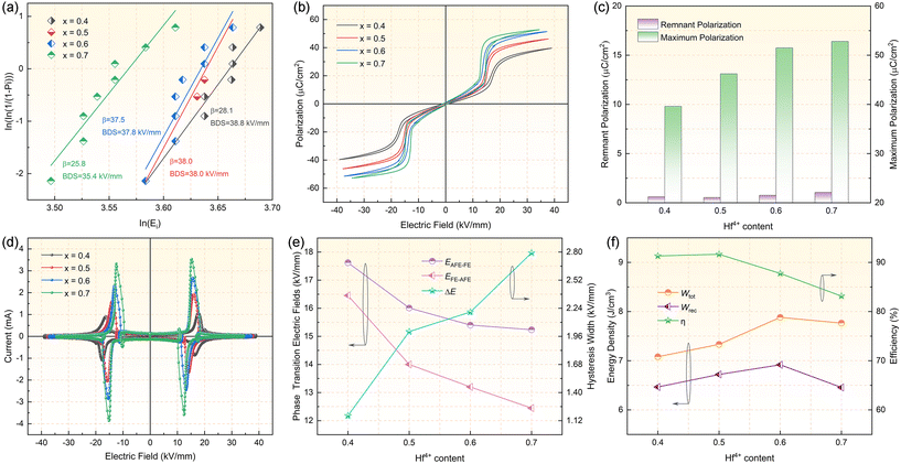
As antiferroelectric ceramics are used for energy storage, their breakdown strength is a crucial parameter. Therefore, the breakdown characteristics of PLHST ceramics can be evaluated using the Weibull distribution, as shown in Fig. 5a. The BDS can be calculated using the following equations:50
Xi = ln![[thin space (1/6-em)]](https://www.rsc.org/images/entities/char_2009.gif) Ei Ei | (4) |
 | (5) |
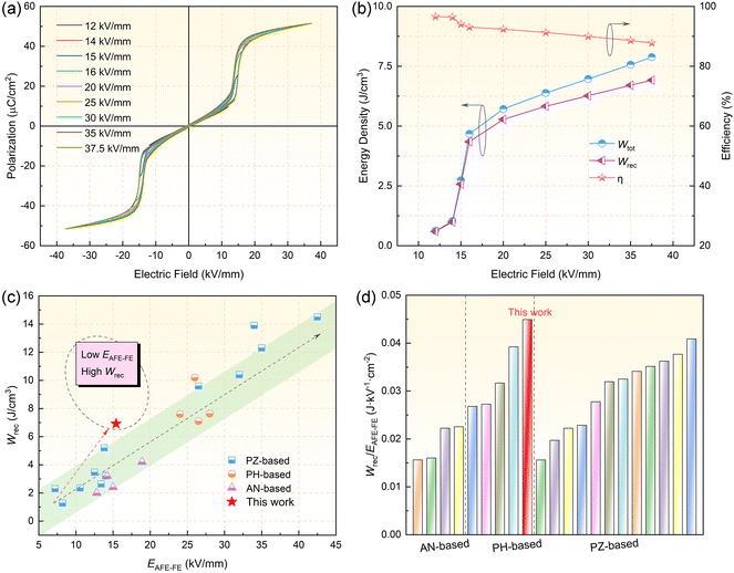
To further investigate the energy storage behavior of the PLHST ceramic with x = 0.6, Fig. 6a shows the P–E loops obtained under various electric fields at 10 Hz. It is clear that the P–E loops remain linear below 14 kV mm−1. As the electric field increases further, double hysteresis loops appear, with a rapid increase in Pmax, eventually reaching saturation. As the electric field increases from 12 to 37.5 kV mm−1, Pmax increases from 9.7 to 51.5 μC cm−2. The P–E loops consistently remain slim, which is conducive to achieving high efficiency.42 The Wtot, Wrec and η values obtained for the PLHST ceramic with x = 0.6 under different electric fields are shown in Fig. 6b. As the electric field increases from 12 kV mm−1 to 16 kV mm−1, there is a significant increase in both Wtot and Wrec, which is attributed to the AFE–FE phase transition. Moreover, as the electric field is further increased to 37.5 kV mm−1, the rates of increase for Wtot and Wrec become more gradual. Despite the decrease of η with the increase of the electric field, the value of η remains consistently above 87% across all electric fields. Fig. 6c depicts a comparison of the AFE–FE phase transition electric field and energy storage density among various AFE materials.7,15,18,19,25–27,32,33,35,39–43,45,50,54–56 Typically, in AFE materials, a high AFE–FE phase transition electric field is necessary to obtain a substantial Wrec. Nonetheless, the PLHST ceramic with x = 0.6 stands out by achieving a relatively high Wrec (6.9 J cm−3) even at a lower AFE–FE phase transition electric field (15.4 kV mm−1). This underscores and further demonstrates the advantageous potential of the PLHST ceramic with x = 0.6 in applications involving safe electric fields. To achieve a more comprehensive evaluation of the Wrec for AFE materials, we introduce a merit value denoted as Wrec/EAFE–FE. The larger the value of Wrec/EAFE–FE, the more it indicates that the material possesses advantages in achieving high energy storage under lower AFE–FE phase transition electric fields, meeting safety and cost-effectiveness requirements, and holds substantial significance for practical applications. Upon comparison (as illustrated in Fig. 6d),7,15,18,19,25–27,32,33,35,39–43,45,50,54–56 it becomes evident that the PLHST ceramic with x = 0.6 surpasses other AFE materials in terms of the Wrec/EAFE–FE value. This serves as a clear demonstration of the potential application of the PLHST ceramic with x = 0.6. Moreover, Fig. S1† presents a comparison of two important parameters (Wrec and η) for recently reported dielectric energy storage materials.2,4,7,9–11,14,17–23,25–31,36,43,52,54–59 High Wrec and η are favourable for practical applications. It can be observed that the PLHST ceramic with x = 0.6 displays an excellent recoverable energy storage density (6.9 J cm−3) and a high energy efficiency (87.8%), demonstrating its potential for use in advanced electronic devices.
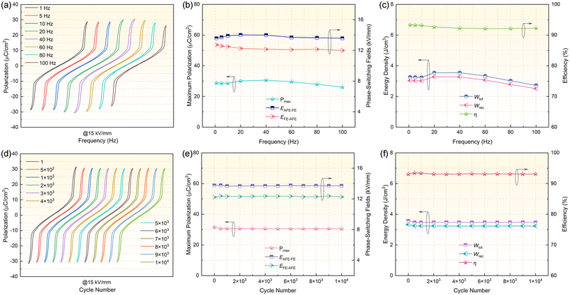
The frequency stability and cycling stability of dielectric materials are two factors that need to be seriously considered, as they determine the operating environment and lifetime of capacitors.10,50Fig. 7a shows the P–E loops of the PLHST ceramic with x = 0.6 under 15 kV mm−1 at different frequencies ranging from 1 to 100 Hz. One can observe that the P–E loops always maintain a slim shape over a wide frequency range, and the corresponding Pmax, EAFE–FE and EFE–AFE are shown in Fig. 7b. It can be noted that the Pmax, EAFE–FE and EFE–AFE remain constant at 26.1–30.6 μC cm−2, 13.5–14.1 kV mm−1, and 11.9–12.7 kV mm−1, respectively, without any significant changes under different frequencies. The calculated Wtot, Wrec and η values based on the P–E loops in Fig. 7a from 1 to 100 Hz are presented in Fig. 7c. It can be found that Wtot, Wrec and η remain at 2.7–3.5 J cm−3, 2.5–3.2 J cm−3 and 92.1–93.2%, respectively. The corresponding variations in Wtot, Wrec and η values are within 22.8%, 21.8% and 1.1%, respectively. In addition, Fig. 7d illustrates the room temperature P–E loops of the PLHST ceramic with x = 0.6 for 1–104 cycles at 15 kV mm−1 and 10 Hz. Obviously, the P–E loops remain almost unchanged even after 104 cycles. Fig. 7e summarizes the corresponding Pmax, EAFE–FE and EFE–AFE values with different fatigue cycles. One can note that the Pmax, EAFE–FE and EFE–AFE remain at 30.5–31.5 μC cm−2, 13.6–13.7 kV mm−1 and 12.2–12.3 kV mm−1, respectively. As a result, the Wtot, Wrec and η values display only a slight variation, remaining at 3.4–3.5 J cm−3, 3.2–3.3 J cm−3 and 93.1–93.4%, respectively. The corresponding variations in Wtot, Wrec and η values are within 2.8%, 3.1% and 0.3%, respectively, as shown in Fig. 7f. Such excellent characteristics indicate that the PLHST ceramic with x = 0.6 exhibits superior frequency stability, along with strong fatigue endurance. Therefore, the PLHST ceramic with x = 0.6 is a promising candidate for practical energy storage devices.
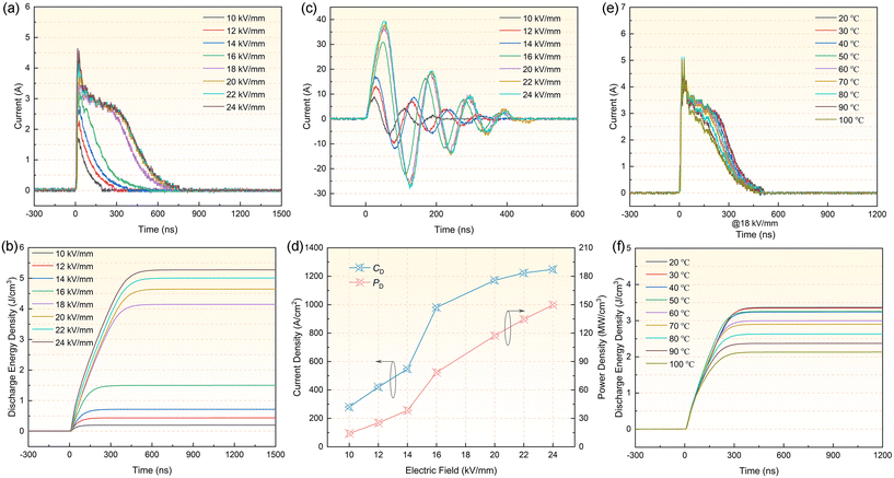
In order to enable the PLHST ceramic with x = 0.6 to be used in pulsed power systems, apart from the theoretical value obtained through P–E loop integration, the actual discharge behavior also needs to be evaluated via a resistance–inductance–capacitance (RLC) circuit.7,28Fig. 8a displays the overdamped discharge current waveforms at different electric fields with an external resistance of 200 Ω. Obviously, the discharge current rapidly peaks with time, and the current amplitude also shows an enhancement trend as the electric field increases. Based on the pulsed discharge curves, the discharge energy density can be calculated using the following formula:15,17
 | (6) |
Fig. 8e shows the temperature stability of the PLHST ceramic with x = 0.6 from 20 to 100 °C at 18 kV mm−1 in an overdamped discharge circuit. As the temperature increases, the ceramic shows similar overdamped discharge behavior, with the peak value of current remaining basically stable, demonstrating excellent temperature stability.7,14,21 In addition, Fig. 8f shows the waveforms of Wdis at different temperatures versus discharge time. It can be seen that over a wide temperature range of 20–100 °C, Wdis decreases slightly, from 3.3 to 2.1 J cm−3. According to the results, the PLHST ceramic with x = 0.6 exhibits outstanding energy storage capability in a broad temperature range of 20 to 100 °C.
4. Conclusions
In summary, (Pb0.97La0.02)(HfxSn0.95−xTi0.05)O3 AFE ceramics with lower phase transition fields were prepared using the tape-casting method. The relationship between Hf4+ content, dielectric properties and energy storage properties was carefully examined. All samples exhibit a perovskite phase and a dense structure. The replacement of Sn4+ with Hf4+ leads to a significant increase in Pmax, from 39.6 to 52.8 μC cm−2, while the AFE–FE phase transition electric field decreases. As a result, the PLHST ceramic with x = 0.6 exhibits a large Wrec of 6.9 J cm−3 together with a high η of 87.8% at a lower AFE–FE phase transition electric field of 15.4 kV mm−1. Meanwhile, the high merit value (Wrec/EAFE–FE) further indicates that the material can achieve a large energy density under lower antiferroelectric to ferroelectric phase transition electric fields. In addition, the energy storage performance of the ceramic exhibits remarkable frequency stability (1–100 Hz) and cycling stability (1 × 10⁴ cycles). In particular, the Wtot and Wrec remain within the range of 2.7–3.5 J cm−3 and 2.5–3.2 J cm−3, respectively, over the frequency range of 1–100 Hz. The variation in Wrec is less than 3.1%, and the η remains higher than 93.1% throughout the 1 × 10⁴ cycles. Moreover, the PLHST ceramic with x = 0.6 exhibits a high Wdis of 5.3 J cm−3 and a superior PD of 149.8 MW cm−3 at 24 kV mm−1, both of which are achieved simultaneously. The PLHST ceramic with x = 0.6 also demonstrates a wide temperature stability range of 20–100 °C. All these characteristics indicate that the (Pb0.97La0.02)(Hf0.6Sn0.35Ti0.05)O3 AFE ceramic emerges as a promising candidate for pulsed power capacitors.Conflicts of interest
We declare that we have no known competing financial interests or personal relationships that could have appeared to influence the work reported in this paper.Acknowledgements
This work was supported by the National Key R&D Program of China (no. 2023YFE0198300).References
- H. Pan, F. Li, Y. Liu, Q. Zhang, M. Wang, S. Lan, Y. Zheng, J. Ma, L. Gu, Y. Shen, P. Yu, S. Zhang, L. Chen, Y. Lin and C. Nan, Ultrahigh-energy density lead-free dielectric films via polymorphic nanodomain design, Science, 2019, 365, 578–582 CrossRef CAS.
- Z. Lu, W. Bao, G. Wang, S.-K. Sun, L. Li, J. Li, H. Yang, H. Ji, A. Feteira, D. Li, F. Xu, A. K. Kleppe, D. Wang, S.-Y. Liu and I. M. Reaney, Mechanism of enhanced energy storage density in AgNbO3-based lead-free antiferroelectrics, Nano Energy, 2021, 79, 105423 CrossRef CAS.
- X. Liu, J. Zhu, Y. Li, T. Yang, X. Hao and W. Gong, High-Performance PbZrO3-based antiferroelectric multilayer capacitors based on multiple enhancement strategy, Chem. Eng. J., 2022, 446, 136729 CrossRef CAS.
- L. Zhao, J. Gao, Q. Liu, S. Zhang and J.-F. Li, Silver Niobate Lead-Free Antiferroelectric Ceramics: Enhancing Energy Storage Density by B-Site Doping, ACS Appl. Mater. Interfaces, 2018, 10, 819–826 CrossRef CAS.
- L. Yang, X. Kong, F. Li, H. Hao, Z. Cheng, H. Liu, J.-F. Li and S. Zhang, Perovskite lead-free dielectrics for energy storage applications, Prog. Mater. Sci., 2019, 102, 72–108 CrossRef CAS.
- Z. Yang, H. Du, L. Jin and D. Poelman, High-performance lead-free bulk ceramics for electrical energy storage applications: design strategies and challenges, J. Mater. Chem. A, 2021, 9, 18026–18085 RSC.
- R. Xu, Q. Zhu, Z. Xu, Y. Feng and X. Wei, PLZST antiferroelectric ceramics with promising energy storage and discharge performance for high power applications, J. Am. Ceram. Soc., 2020, 103, 1831–1838 CrossRef CAS.
- Y. Li, G. Wang, A. Gong, S. Zhang, J. Liu, N. Sun and X. Hao, High-Performance Ferroelectric Electromagnetic Attenuation Materials with Multiple Polar Units Based on Nanodomain Engineering, Small, 2022, 18, 2106302 CrossRef CAS.
- L. Zhang, S. Jiang, Y. Zeng, M. Fu, K. Han, Q. Li, Q. Wang and G. Zhang, Y doping and grain size co-effects on the electrical energy storage performance of (Pb0.87Ba0.1La0.02) (Zr0.65Sn0.3Ti0.05)O3 anti-ferroelectric ceramics, Ceram. Int., 2014, 40, 5455–5460 CrossRef CAS.
- M. Zhou, R. Liang, Z. Zhou and X. Dong, Superior energy storage properties and excellent stability of novel NaNbO3-based lead-free ceramics with A-site vacancy obtained via a Bi2O3 substitution strategy, J. Mater. Chem. A, 2018, 6, 17896–17904 RSC.
- Z. Yang, H. Du, L. Jin, Q. Hu, H. Wang, Y. Li, J. Wang, F. Gao and S. Qu, Realizing high comprehensive energy storage performance in lead-free bulk ceramics via designing an unmatched temperature range, J. Mater. Chem. A, 2019, 7, 27256 RSC.
- X. Yang, Y. Liu, C. He, H. Tailor and X. Long, La-modified Pb(Lu1/2Nb1/2)O3, antiferroelectric ceramics with high energy storage density, J. Eur. Ceram. Soc., 2015, 35, 4173–4180 CrossRef CAS.
- H. Yang, J. Tian, Y. Lin and J. Ma, Realizing ultra-high energy storage density of lead-free 0.76Bi0.5Na0.5TiO3-0.24SrTiO3-Bi(Ni2/3Nb1/3)O3 ceramics under low electric fields, Chem. Eng. J., 2021, 418, 129337 CrossRef CAS.
- R. Shi, Y. Pu, W. Wang, X. Guo, J. Li, M. Yang and S. Zhou, A novel lead-free NaNbO3–Bi(Zn0.5Ti0.5)O3 ceramics system for energy storage application with excellent stability, J. Alloys Compd., 2020, 815, 152356 CrossRef CAS.
- X. Liu, T. Yang, B. Shen and L. Chen, Enhancing the Energy Storage Performance in Lead-Based Antiferroelectric Ceramics via Pb(Zr0.88Sn0.12)O3/(Pb0.875La0.05Sr0.05)(Zr0.695Ti0.005Sn0.3)O3-Derived Laminated Composite Structures, ACS Appl. Energy Mater., 2023, 6, 1218–1227 CrossRef CAS.
- K. Huang, G. Ge, F. Yan, B. Shen and J. Zhai, Ultralow electrical hysteresis along with high energy-storage density in lead-based antiferroelectric ceramics, Adv. Electron. Mater., 2020, 6, 1901366 CrossRef CAS.
- J. Chen, H. Qi and R. Zuo, Realizing Stable Relaxor Antiferroelectric and Superior Energy Storage Properties in (Na1−x/2Lax/2)(Nb1−xTix)O3 Lead-Free Ceramics through A/B-Site Complex Substitution, ACS Appl. Mater. Interfaces, 2020, 12, 32871–32879 CrossRef CAS PubMed.
- J. Gao, L. Zhao, Q. Liu, X. Wang, S. Zhang and J.-F. Li, Antiferroelectric-ferroelectric phase transition in lead-free AgNbO3 ceramics for energy storage applications, J. Am. Ceram. Soc., 2018, 101, 5443–5450 CrossRef CAS.
- L. Chen, X. Hao, Q. Zhang and S. An, Energy-storage performance of PbO–B2O3–SiO2 added (Pb0.92Ba0.05La0.02)(Zr0.68Sn0.27Ti0.05)O3 antiferroelectric ceramics prepared by microwave sintering method, J. Mater. Sci.: Mater. Electron., 2016, 27, 4534–4540 CrossRef CAS.
- L. Yang, X. Kong, Z. Cheng and S. Zhang, Enhanced Energy Storage Performance of Sodium Niobate-Based Relaxor Dielectrics by a Ramp-to-Spike Sintering Profile, ACS Appl. Mater. Interfaces, 2020, 12, 32834–32841 CrossRef CAS.
- M. Zhou, R. Liang, Z. Zhou, S. Yan and X. Dong, Novel Sodium Niobate-Based Lead-Free Ceramics as New Environment-Friendly Energy Storage Materials with High Energy Density, High Power Density, and Excellent Stability, ACS Sustainable Chem. Eng., 2018, 6, 12755–12765 CrossRef CAS.
- Y. Liu, T. Yang and H. Wang, Effect of La doping on structure and dielectric properties of PLZST antiferroelectric ceramics, J. Mater. Sci.: Mater. Electron., 2020, 31, 1509–1514 CrossRef CAS.
- A. Tian, R. Zuo, H. Qi and M. Shi, Large energy-storage density in transition-metal oxide modified NaNbO3–Bi(Mg0.5Ti0.5)O3 lead-free ceramics through regulating the antiferroelectric phase structure, J. Mater. Chem. A, 2020, 8, 8352–8359 RSC.
- X. Hao, J. Zhai, L. B. Kong and Z. Xu, A comprehensive review on the progress of lead zirconate-based antiferroelectric materials, Prog. Mater. Sci., 2014, 63, 1–57 CrossRef CAS.
- P. Liu, Y. Zhang, Y. Zhu, B. Fan, W. Li, H. Zhang and S. Jiang, Structure variation and energy storage properties of acceptor-modified PBLZST antiferroelectric ceramics, J. Am. Ceram. Soc., 2019, 102, 1912–1920 CrossRef CAS.
- Y. Dan, H. Xu, K. Zou, Q. Zhang, Y. Lu, G. Chang, H. Huang and Y. He, Energy storage characteristics of (Pb,La)(Zr,Sn,Ti)O3 antiferroelectric ceramics with high Sn content, Appl. Phys. Lett., 2018, 113, 063902 CrossRef.
- Z. Liu, Y. Bai, X. Chen, X. Dong, H. Nie, F. Cao and G. Wang, Linear composition-dependent phase transition behavior and energy storage performance of tetragonal PLZST antiferroelectric ceramics, J. Alloys Compd., 2017, 691, 721–725 CrossRef CAS.
- N. Luo, K. Han, M. J. Cabral, X. Liao, S. Zhang, C. Liao, G. Zhang, X. Chen, Q. Feng, J.-F. Li and Y. Wei, Constructing phase boundary in AgNbO3 antiferroelectrics: pathway simultaneously achieving high energy density and efficiency, Nat. Commun., 2020, 11, 4824 CrossRef CAS.
- M. Zhou, R. Liang, Z. Zhou and X. Dong, Achieving ultrahigh energy storage density and energy efficiency simultaneously in sodium niobate-based lead-free dielectric capacitors via microstructure modulation, Inorg. Chem. Front., 2019, 6, 2148–2157 RSC.
- Z. Yang, H. Du, L. Jin, Q. Hu, S. Qu, Z. Yang, Y. Yu, X. Wei and Z. Xu, A new family of sodium niobate-based dielectrics for electrical energy storage applications, J. Eur. Ceram. Soc., 2019, 39, 2899–2907 CrossRef CAS.
- S. Li, H. Nie, G. Wang, C. Xu, N. Liu, M. Zhou, F. Cao and X. Dong, Novel AgNbO3-based lead-free ceramics featuring excellent pyroelectric properties for infrared detecting and energy-harvesting applications via antiferroelectric/ferroelectric phase-boundary design, J. Mater. Chem. C, 2019, 7, 4403–4414 RSC.
- H. Wang, Y. Liu, T. Yang and S. Zhang, Ultrahigh Energy-Storage Density in Antiferroelectric Ceramics with Field-Induced Multiphase Transitions, Adv. Funct. Mater., 2019, 29, 1807321 CrossRef.
- X. Meng, Y. Zhao, Y. Li and X. Hao, Systematical investigation on energy-storage behavior of PLZST antiferroelectric ceramics by composition optimizing, J. Am. Ceram. Soc., 2021, 104, 2170–2180 CrossRef CAS.
- S. Jiang, L. Zhang, G. Zhang, S. Liu, J. Yi, X. Xiong, Y. Yu, J. He and Y. Zeng, Effect of Zr:Sn ratio in the lead lanthanum zirconate stannate titanate anti-ferroelectric ceramics on energy storage properties, Ceram. Int., 2013, 39, 5571–5575 CrossRef CAS.
- H. Xu, Y. Dan, K. Zou, G. Chen, Q. Zhang, Y. Lu and Y. He, Superior energy storage performance in Pb0.97La0.02(Zr0.50Sn0.43Ti0.07)O3 antiferroelectric ceramics, J. Mater. Res. Technol., 2019, 8, 3291–3296 CrossRef CAS.
- P. Gao, Z. Liu, N. Zhang, H. Wu, A. A. Bokov, W. Ren and Z. Ye, New Antiferroelectric Perovskite System with Ultrahigh Energy-Storage Performance at Low Electric Field, Chem. Mater., 2019, 31, 979–990 CrossRef CAS.
- X.-X. Huang, P.-Z. Ge, T.-F. Zhang, Q.-X. Liu, Y.-P. Jiang, Z.-H. Tang, X.-B. Guo and X.-G. Tang, Composition-tailor induced electrocaloric effect near room temperature in (Pb,Ba)HfO3 films, J. Materiomics, 2023, 9, 502–509 CrossRef.
- G. Shirane and R. Pepinsky, Phase Transitions in Antiferroelectric PbHfO3, Phys. Rev., 1953, 91, 812–815 CrossRef CAS.
- J. Wei, T. Yang and H. Wang, Excellent Energy Storage and Charge-discharge Performances in PbHfO3 Antiferroelectric Ceramics, J. Eur. Ceram. Soc., 2019, 39, 624–630 CrossRef CAS.
- P.-Z. Ge, X.-G. Tang, K. Meng, X.-X. Huang, S.-F. Li, Q.-X. Liu and Y.-P. Jiang, Energy storage density and charge–discharge properties of PbHf1−xSnxO3 antiferroelectric ceramics, Chem. Eng. J., 2022, 429, 132540 CrossRef CAS.
- R. Xu, M. Wang, Q. Zhu, Z. Xu, Y. Feng and X. Wei, Investigation on antiferroelectricity of Pb0.97La0.02(Hf1−xTix)O3 ceramics with low Ti content (0 ≤ x ≤ 0.1), J. Am. Ceram. Soc., 2022, 105, 7438–7445 CrossRef CAS.
- X. Liu, T. Yang and W. Gong, Comprehensively enhanced energy-storage properties in (Pb1–3x/2Lax)(Zr0.995Ti0.005)O3 antiferroelectric ceramics via composition optimization, J. Mater. Chem. C, 2021, 9, 12399–12407 RSC.
- L. Zhao, Q. Liu, J. Gao, S. Zhang and J.-F. Li, Lead-Free Antiferroelectric Silver Niobate Tantalate with High Energy Storage Performance, Adv. Mater., 2017, 19, 1701824 CrossRef.
- J. Shen, X. Wang, T. Yang, H. Wang and J. Wei, High discharge energy density and fast release speed of (Pb, La)(Zr, Sn, Ti)O3 antiferroelectric ceramics for pulsed capacitors, J. Alloys Compd., 2017, 721, 191–198 CrossRef CAS.
- W. Chao, T. Yang and Y. Li, Achieving high energy efficiency and energy density in PbHfO3-based antiferroelectric ceramics, J. Mater. Chem. C, 2020, 8, 17016 RSC.
- R. D. Shannon, Revised Effective Ionic Radii and Systematic Studies of Interatomic Distances in Halides and Chalcogenides, Acta Crystallogr., Sect. A: Cryst. Phys., Diffr., Theor. Gen. Crystallogr., 1976, 32, 751–767 CrossRef.
- W. Chao, L. Tian, T. Yang, Y. Li and Z. Liu, Excellent energy storage performance achieved in novel PbHfO3-based antiferroelectric ceramics via grain size engineering, Chem. Eng. J., 2022, 433, 133814 CrossRef CAS.
- H. Yang, F. Yan, Y. Lin, T. Wang, F. Wang, Y. Wang, L. Guo, W. Tai and H. Wei, Lead-free BaTiO3-Bi0.5Na0.5TiO3-Na0.73Bi0.09NbO3 relaxor ferroelectric ceramics for high energy storage, J. Eur. Ceram. Soc., 2017, 37, 3303–3311 CrossRef CAS.
- Z. Yang, H. Du, S. Qu, Y. Hou, H. Ma, J. Wang, J. Wang, X. Wei and Z. Xu, Significantly enhanced recoverable energy storage density in potassium-sodium niobate-based lead free ceramics, J. Mater. Chem. A, 2016, 4, 13778–13785 RSC.
- X. Liu, T. Yang and W. Gong, Achieving ultrahigh energy-storage capability in PbZrO3-based antiferroelectric capacitors based on optimization of property parameters, J. Mater. Chem. A, 2022, 10, 4137–4145 RSC.
- M.-Y. Zhao, J. Wang, L. Chen, H. Yuan, M.-H. Zhang, S.-W. Zhang and L. Zhao, Enhanced breakdown strength and energy storage density of AgNbO3 ceramics via tape casting, Rare Met., 2023, 42, 495–502 CrossRef CAS.
- N. Luo, K. Han, F. Zhuo, C. Xu, G. Zhang, L. Liu, X. Chen, C. Hu, H. Zhou and Y. Wei, Aliovalent A-site engineered AgNbO3 lead-free antiferroelectric ceramics toward superior energy storage density, J. Mater. Chem. A, 2019, 7, 14118–14128 RSC.
- R. D. Shannon and R. X. Fischer, Empirical electronic polarizabilities in oxides, hydroxides, oxyfluorides, and oxychlorides, Phys. Rev. B: Condens. Matter Mater. Phys., 2006, 73, 23511 CrossRef.
- P. Qiao, X. Chen, Z. Liu, G. Wang and X. Dong, Enhanced energy storage performance in Pb0.97La0.02(ZrxSn0.90−xTi0.10)O3 antiferroelectric ceramics, Mater. Lett., 2020, 260, 126877 CrossRef CAS.
- C. Xu, Z. Fu, Z. Liu, L. Wang, S. Yan, X. Chen, F. Cao, X. Dong and G. Wang, La/Mn Co-doped AgNbO3 Lead-Free Antiferroelectric Ceramics with Large Energy Density and Power Density, ACS Sustainable Chem. Eng., 2018, 6, 16151–16159 CrossRef CAS.
- A. Song, J. Song, Y. Lv, L. Liang, J. Wang and L. Zhao, Energy storage performance in BiMnO3-modified AgNbO3 anti-ferroelectric ceramics, Mater. Lett., 2019, 237, 278–281 CrossRef CAS.
- Y. Tian, L. Jin, H. Zhang, Z. Xu, X. Wei, G. Viola, I. Abrahams and H. Yan, Phase transitions in bismuth-modified silver niobate ceramics for high power energy storage, J. Mater. Chem. A, 2017, 5, 17525–17531 RSC.
- Y. Tian, L. Jin, H. Zhang, Z. Xu, X. Wei, E. Politova, S. Y. Stefanovich, N. V. Tarakina, I. Abrahams and H. Yan, High energy density in silver niobate ceramics, J. Mater. Chem. A, 2016, 4, 17279–17287 RSC.
- W. Chao, T. Yang, Y. Li and Z. Liu, Enhanced energy storage density in Ca and Ta co-doped AgNbO3 antiferroelectric ceramics, J. Am. Ceram. Soc., 2020, 103, 7283–7290 CrossRef CAS.
- R. Xu, J. Tian, Q. Zhu, T. Zhao, Y. Feng, X. Wei and Z. Xu, Effects of phase transition on discharge properties of PLZST antiferroelectric ceramics, J. Am. Ceram. Soc., 2017, 100, 3618–3625 CrossRef CAS.
Footnote |
| † Electronic supplementary information (ESI) available. See DOI: https://doi.org/10.1039/d3qi01924a |
| This journal is © the Partner Organisations 2024 |


