
Synthesis of high-entropy germanides and investigation of their formation process†
Chuyi
Ni
 ,
Kevin M.
O’Connor
,
Cole
Butler
and
Jonathan G. C.
Veinot
*
,
Kevin M.
O’Connor
,
Cole
Butler
and
Jonathan G. C.
Veinot
*
Department of Chemistry, University of Alberta, Edmonton, Alberta T6G 2G2, Canada. E-mail: jveinot@ualberta.ca
First published on 1st March 2024
Abstract
High-entropy alloys and compounds have emerged as an attractive research area in part because of their distinctive solid-solution structure and multi-element compositions that provide near-limitless tailorability. A diverse array of reports describing high-entropy compounds, including carbides, nitrides, sulfides, oxides, fluorides, silicides, and borides, has resulted. Strikingly, exploration of high-entropy germanides (HEGs) has remained relatively limited. In this study, we present a detailed investigation into the synthesis of HEGs, specifically AuAgCuPdPtGe and FeCoNiCrVGe, via a rapid thermal annealing. The structural, compositional, and morphological characteristics of the synthesized HEGs were assessed using laboratory X-ray diffraction (XRD), Fourier-transform infrared spectroscopy (FTIR), X-ray photoelectron spectroscopy (XPS), and transmission electron microscopy (TEM). Complementing these post-synthesis analyses, we interrogated the formation and growth mechanisms using in situ heating XRD and TEM and determined that HEG formation involved initial decomposition of germanane (GeNSs) during the annealing, followed by gradual grain growth via atom diffusion at temperatures below 600 °C, and finally a rapid grain growth process at elevated temperatures.
New conceptsWe present a novel approach for the synthesis of high-entropy germanides (HEGs) via a rapid thermal annealing. Prior to this contribution, the synthesis of HEGs has been comparatively constrained in comparison to other high-entropy compounds such as carbides, oxides, nitrides, sulfides, fluorides, silicides, and borides. Building upon our prior research involving high-entropy alloy nanoparticles decorated GeNSs (HEA NPs@GeNSs), we elucidate the conversion process from HEA NPs@GeNSs and metal salts&GeNSs to HEGs. Additionally, we investigate the formation mechanism of HEGs by in situ heating XRD and TEM analyses, revealing a sequential progression initiated by the decomposition of GeNSs during annealing, followed by gradual grain growth facilitated by atom diffusion at temperatures below 600 °C, culminating in a rapid grain growth process at elevated temperatures. Overall, this work provides promising results in the field of high-entropy compounds and opens new avenues for the investigation of their formation. |
Introduction
High-entropy alloy nanoparticles (HEA NPs) have emerged as a captivating and challenging class of materials.1 The considerable attention bestowed upon these materials can be attributed, in part, to their intricate multi-elemental compositions and distinctive high-entropy solid-solution structures, which collectively impart tunable reactivity and enhanced stability and make HEA NPs appealing candidate materials in catalyst development.2 The seminal advancement in synthesis of HEA NPs, which exhibit a wide compositional range encompassing numerous immiscible metal combinations and incorporating up to eight constituent elements, was achieved using what has come to be known as the “carbo-thermal shock” method.3 Subsequently, several complementary procedures have been developed to prepare HEA NPs, including vapor phase spark discharge, rapid radiative heating or annealing, low-temperature hydrogen spillover, microwave heating, and colloidal methods.4–13 In the wake of these advancements, diverse high-entropy compounds, such as oxides,14 fluorides,15 sulfides,16 carbides,17 nitrides,18 silicide,19 borides,20 stannides,21 and halide perovskites22 have been successfully demonstrated. It is noteworthy that germanides have remained unexplored as high-entropy nanomaterials.Germanides are a class of materials that have garnered significant attention because of their potential thermoelectric and electronic applications.23,24 These compounds are formed by combining germanium with diverse metallic elements such as iron, nickel, cobalt, and palladium.25–28 Germanides are characterized by high electrical conductivity, low thermal conductivity, and favorable thermoelectric characteristics that make them attractive.24,29,30 As such, germanides have emerged as promising active materials for thermoelectric generators, coolers, and electronic devices (e.g., transistors, diodes, integrated circuit interconnects).27,28,30–32 Embracing the principles of high-entropy alloying can provide enhancement of thermoelectric performance and substantial progress has been achieved in the field of high-performance high-entropy alloy thermoelectrics.23,33,34 Still, examples of high-entropy alloying involving germanides remain underexplored.32
In our recent report, we presented a solution-based method for preparing high-entropy alloy nanoparticle-decorated germanane (HEA NPs@GeNSs).35 Using this method, we successfully prepared HEA NPs (comprising Au, Ag, Cu, Pd, and Pt) on the surface of germanane. Recognizing that the Ge–H terminated surface germanane serves as a reducing agent and the underlying Ge atoms could potentially provide a Ge source that could facilitate the formation of high-entropy germanides (HEGs), we have now explored transforming HEA NPs@GeNSs into a HEG (AuAgCuPdPtGe) (Scheme 1) via rapid thermal annealing. These promising findings motivated us to target HEA NPs@GeNSs of different metal compositions and the formation of corresponding HEGs. Given that first-row transition metals (Sc, Ti, V, Cr, Mn, Fe, Co, Ni) can be incorporated into single-phase HEA NPs and are readily prepared as high-entropy oxides,36 we chose to investigate several of these elements (i.e., V, Cr, Fe, Co, Ni) as potential components for high-entropy germanide formation.
 | ||
| Scheme 1 A pictorial representation of the formation of high-entropy germanide (HEG: AuAgCuPdPtGe) from high-entropy alloy nanoparticles decorated germanane (HEA NPs@GeNSs). HEA NPs@GeNSs were rapid annealed at 800 °C under Ar flow for 10 minutes. The products were collected after rapidly cooling to room temperature. (Note: for clarity, hydrogen atoms on the germanane surfaces are not shown.) | ||
Moreover, we have delved into the formation processes that yield HEGs using in situ heating X-ray diffraction and transmission electron microscopy. Our experimental observations revealed that at elevated temperatures (300 °C), germanane decomposes providing into germanium nanoparticles that the high-entropy components subsequently diffuse into. At comparatively low temperatures, this process is slow with diffusion proceeding more rapidly when temperature exceeds 600 °C.
Synthesis of AuAgCuPdPtGe HEG
Germanane used in the present study was prepared via topotactic deintercalation of calcium digermanide (Scheme S1, ESI†).37 Following the deintercalation process, the resulting product was placed in distilled water and the mixture was subjected to a bath sonicator for 2 hours to achieve optimal exfoliation. Subsequently, the exfoliated germanane was combined with an aqueous solution containing the desired metal salts (i.e., AuCl3, AgNO3, CuCl2, PdCl2, PtCl4). The Ge–H on the surfaces of the germanane immediately reacted with the aqueous metal ions35 leading to the formation of size-polydisperse HEA NPs (AuAgCuPdPt) on the surfaces of the germanane (Scheme S1, ESI†). The resulting HEA NPs@GeNS powder was collected and heated to 800 °C at 1 °C s−1 in flowing Ar. After annealing at the peak temperature for 10 min, the product was rapidly cooled to room temperature by removing the tube from the furnace and flushing the reaction tube with a constant flow of N2 gas. This process led to the formation of the desired AuAgCuPdPtGe HEG (Scheme 1).Powder X-ray diffraction (XRD) was used to evaluate the crystal structure of AuAgCuPdPtGe HEG. The XRD pattern of HEA NPs@GeNSs (Fig. S1, ESI†) showed characteristic reflections of HEA NPs and GeNSs.35 After annealing, the pattern of AuAgCuPdPtGe HEG exhibited characteristic FCC reflections. Notably, these reflections exhibited a slight shift to higher angles (27.33°, 45.35°, 53.78°, 66.07°, 72.89°) when compared to a Ge standard (27.28°, 45.30°, 53.69°, 65.99°, 72.81°) consistent with the incorporation of multiple elements (i.e., Au, Ag, Cu, Pd, Pt) into the Ge crystal structure resulting in a strained lattice.15 We determined the lattice parameter for the AuAgCuPdPtGe HEG using Vegard's Law (Fig. S3, ESI†). A deviation from the linear variation of the lattice parameters was observed for the AuAgCuPdPtGe HEG suggesting strain is present that arises from the incorporation of the small atoms (i.e., Au, Ag, Cu, Pd, Pt).38 We also noted reflections arising from GeO2 impurities in the XRD analysis, which we confidently attribute to the crystallization of residual oxidized surface germanium species.39 The broadening of the HEG reflections was evaluated using the Scherrer equation and provided an estimated crystallite size of 62.8 ± 1.9 nm.40 Consistent with our lattice parameter data, consideration of the diffraction angle dependence of peak broadening (Fig. S2, ESI†) also reveals that strain-induced broadening is manifested in the AuAgCuPdPtGe HEG system.35
To further investigate the nature of the AuAgCuPdPtGe HEG, we interrogated the product using Fourier-transform infrared (FTIR) and X-ray photoelectron spectroscopy (XPS). The FTIR spectrum (Fig. S4, ESI†) of the parent HEA NPs@GeNSs exhibited prominent features attributed to Ge–H stretching modes at 2000 cm−1 and Ge–O stretching modes in the range of 700 to 890 cm−1.35 Following annealing, the FTIR spectrum of the resulting AuAgCuPdPtGe HEG displayed no discernible feature at 2000 cm−1. The absence of the Ge–H stretching mode is consistent with thermal cleavage of Ge–H bonds.41
XPS provides additional insight into the material composition, bonding environment, and oxidation states of elements in the present materials. The survey XP spectrum of the AuAgCuPdPtGe HEG corroborated the findings from FTIR and XRD analyses, revealing evidence of oxidation and corresponding metal emissions (Fig. S5, ESI†). Integration of the emission peaks in the survey XP spectra provided quantification of the composition of the AuAgCuPdPtGe HEG. The surface atomic percentages for each metal were approximately 14 atomic %, while that of Ge was around 27.1 atomic %. These results provide an approximate composition of Au0.54Ag0.53Cu0.55Pd0.55Pt0.53Ge (Table S1, ESI†), in which higher Ge amount results from residual GeO2 noted in the XRD and FTIR analyses.
High-resolution XP spectra of the AuAgCuPdPtGe HEG revealed emissions associated with the corresponding metals (Au, Ag, Cu, Pd, and Pt) and Ge (Fig. S6, ESI†). The Ge 3d spectra showed a shift to a lower binding energy of 29.5 eV, when compared to Ge in the GeNSs (29.8 eV).42 This shift is in agreement with the Ge atoms in the HEG being bonded to atoms that are less electronegative than hydrogen. Among the constituent metals in the present AuAgCuPdPtGe HEG, only Ge, Cu, and Ag fit this criterion (Table S1, ESI†). We also note that the measured binding energy of Ge in AuAgCuPdPtGe HEG is comparable to that of crystalline germanium (c-Ge; 29.5 eV),37 suggesting a random mixing effect has averaged the influence of the electronegativity of atoms neighboring germanium. Additionally, we note fit components in the Ge 3d emission appearing at 31.3 and 32.5 eV that have previously been attributed to Ge2+ and Ge4+ species, arise from the presence of GeO2 (Fig. S6a, ESI†) that are consistent with our XRD and FTIR analyses.37 Turning our attention to the metal constituents, the XP spectra of each showed emissions at binding energies characteristic of their corresponding metallic state (i.e., Au 4f7/2, 84.0 eV; Ag 3d5/2, 368.0 eV; Cu 2p3/2, 932.1 eV; Pd 3d5/2, 335.0 eV; Pt 4f7/2, 71.0 eV). These findings are attributed to the random distribution of atoms in the high-entropy germanide structure,43 and support the successful formation of the HEG.
Electron microscopy techniques were employed for the investigation of the nano-morphology of the AuAgCuPdPtGe HEG. High-resolution transmission electron microscopy (HRTEM) image (Fig. 1) confirms the formation of pseudospherical HEG particles with dimensions 63.4 ± 4.5 nm (Fig. S7a, ESI†), while highly crystalline GeO2 was observed surrounding the germanide (Fig. S7b, ESI†). Low-resolution bright-field TEM imaging (Fig. S7c, ESI†) shows the polydispersity of the AuAgCuPdPtGe HEG surrounded with crystalline GeO2. High-angle annular dark-field scanning transmission electron microscopy (HAADF-STEM) images show AuAgCuPdPtGe HEG morphologies consistent with bright-field imaging (Fig. 1b) and EDX mapping confirms co-localization of all metals and Ge in the morphological features (Fig. 1c–h). On rare occasions localized element distribution mapping may vary slightly. We propose this arises from inhomogeneous distribution of metal salts used to prepare the HEA NPs@GeNSs. The EDX spectrum (Fig. S8, ESI†) provides signatures for Ge (i.e., ca. 21 atomic %) and the other five target metals (i.e., ca. 6 atomic %). Collectively, these findings, with XPS analyses, support the conclusion that the germanide exhibits homogeneity and there is no evidence of surface segregation or phase separation.
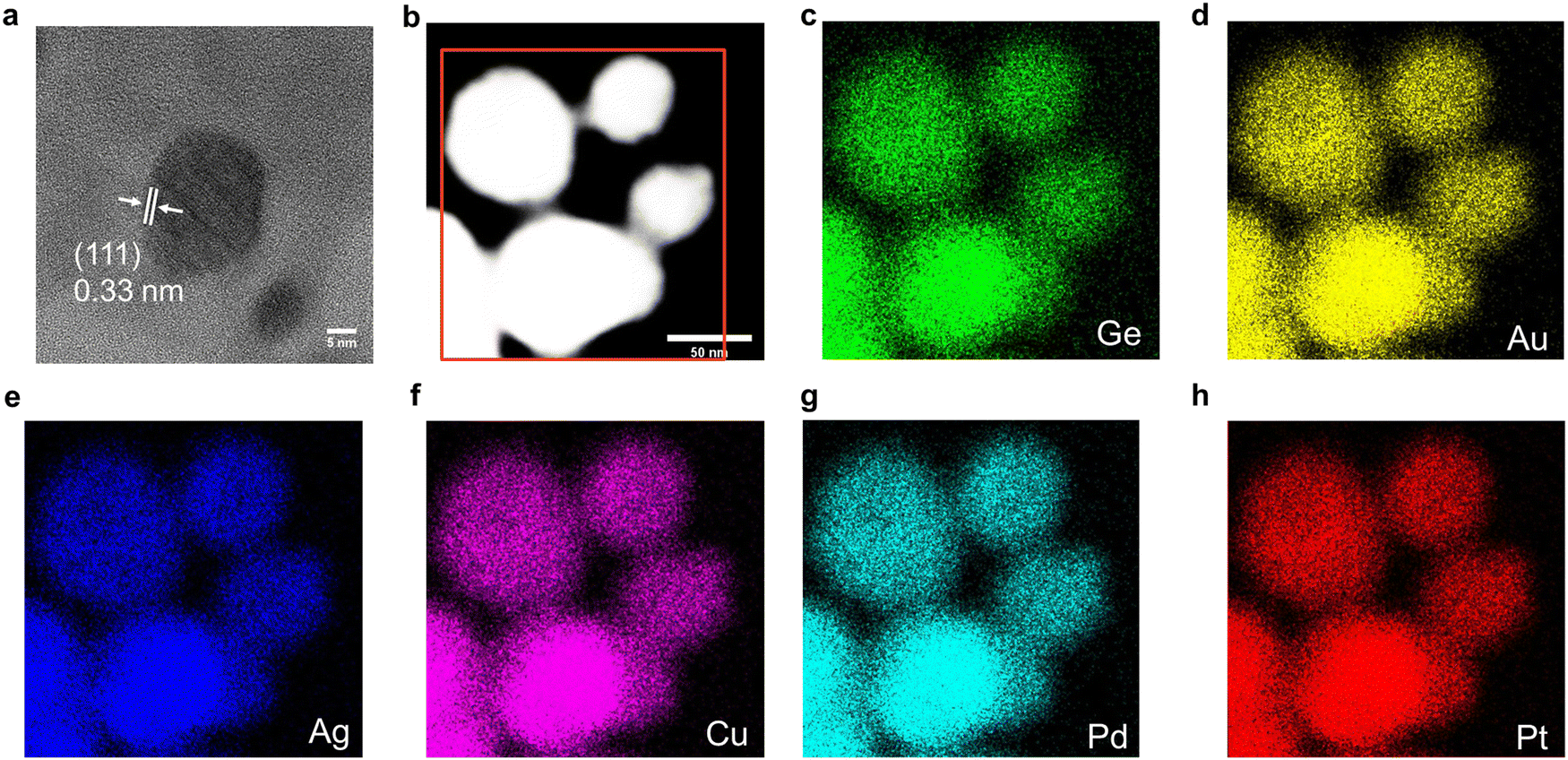 | ||
| Fig. 1 TEM and EDX analysis of the AuAgCuPdPtGe HEG. (a) High-resolution image showing characteristic (111) lattice spacing. (b) HAADF-STEM image and (c)–(h) corresponding EDX mapping of the indicated elements in the red region. | ||
Synthesis of FeCoNiCrVGe HEG
Having demonstrated the feasibility of annealing HEA NPs@GeNSs as a convenient approach to preparing high-entropy germanides, we explored using alternative metals exhibiting lower redox potentials. While previous studies have focused on noble metals possessing positive redox potentials, we directed our attention to the first-row transition metals, V, Cr, Fe, Co, and Ni. The negative redox potentials of these transition metals hinders the direct reduction of the metal ion by GeNSs for metal nanoparticles deposition. To address this, we synthesized a FeCoNiCrVGe HEG by initially mixing GeNSs with a solution comprising metal salts (i.e., FeCl3, VCl3, CrCl2, CoCl2, NiCl2) followed by solvent removal through rotary evaporation. The resulting slurry was heated to 800 °C at 1 °C s−1 under Ar flow. The sample was maintained at the peak temperature for 10 minutes, after which the product was quenched to room temperature by removing the tube from the furnace and flushing the tube with N2 gas (Scheme S2, ESI†).The crystal structure and bonding of the FeCoNiCrVGe HEG were investigated using XRD and FTIR spectroscopy. The XRD pattern of metal salts&GeNSs precursor (Fig. S9, ESI†) is dominated by the characteristic reflections from GeNSs. No salt related reflections are noted because of their low concentration. After annealing (Fig. S9, ESI†) FCC reflections from FeCoNiCrVGe HEG were observed while no reflections associated with GeNSs were detected. We also note that the reflections associated with the FeCoNiCrVGe HEG appeared at slightly higher angles (27.32°, 45.34°, 53.74°, 66.06°, 72.90°) compared to the Ge reflections (27.28°, 45.30°, 53.69°, 65.99°, 72.81°). The reflections of GeO2 were also observed, but with lower intensity in comparison with the AuAgCuPdPtGe HEG. This finding suggests the metal salt-loaded GeNS precursor contained fewer oxidized Ge surface species and implies that the GeNSs exhibited limited reactivity toward the metal salts used (i.e., FeCl3, VCl3, CrCl2, CoCl2, NiCl2). Scherrer analysis provides an estimated crystallite size of 55.3 ± 1.7 nm and the broadening distribution of the FeCoNiCrVGe HEG indicated the presence of strain-induced broadening (Fig. S10a, ESI†). We also determined the lattice parameter for the FeCoNiCrVGe HEG using Vegard's Law (Fig. S10b, ESI†) and found that a similar deviation from the linear variation of the lattice parameters due to the incorporation of the small atoms. In the FTIR spectrum of the precursor (Fig. S11, ESI†), a dominant Ge–H stretching vibration was observed at 2000 cm−1; of note there is no apparent Ge–O vibration feature in the range of 700 to 800 cm−1. Consistent with the presented XRD analyses, after annealing a significant Ge–O peak emerged at 800 cm−1 and there is no evidence of the Ge–H feature.
XPS was used to investigate the elemental composition and oxidation states of the resulting FeCoNiCrVGe HEG. The survey spectrum (Fig. S12, ESI†) showed the expected metal (approximately 15 atomic %) and Ge (24.2 atomic %) emissions, indicating an approximate composition of Fe0.63Co0.62Ni0.64Cr0.63V0.61Ge (Table S2, ESI†); as with the AuAgCuPdPtGe HEG, we note higher proportions of Ge that we attribute to the presence of GeO2. The high-resolution spectra of the metal components within the FeCoNiCrVGe HEG exhibited high oxidation states (Fig. S12 (ESI†); V3+ 2p3/2, 515.7 eV; Cr3+ 2p3/2, 576.9 eV; Fe2+ 2p3/2, 709.6 eV; Co2+ 2p3/2, 779.6 eV and Ni+ 2p3/2, 853.0 eV) and the metal emissions are shifted to higher binding energies compared to their metallic state. This shift is attributed to the comparatively high electronegativity of Ge when relative to the metals (Table S2, ESI†).44,45 The difference in electronegativity between the elements affects their binding energies, with a larger difference resulting in greater shift.20 Correspondingly, the Ge 3d region (Fig. S13a, ESI†) provided a binding energy of 29.2 eV which was lower than the binding energy of c-Ge (29.5 eV). This shift in Ge 3 d binding energy is consistent with the average electronegativity of neighboring atoms is lower than that of Ge itself.45 It should be noted that all of the metals (Fe, Co, Ni, Cr, V) in the HEG exhibit lower electronegativities compared to the previous noble metals and Ge (Table S2, ESI†).
HRTEM imaging (Fig. 2a) confirmed the formation of an FeCoNiCrVGe HEG with particle dimensions of 55.8 ± 3.4 nm (Fig. S14a, ESI†) and low-resolution bright-field TEM imaging (Fig. S14b, ESI†) shows the polydispersity of the FeCoNiCrVGe HEG. Morphology of our FeCoNiCrVGe HEG was further interrogated using HAADF-STEM imaging (Fig. 2b) while EDX mapping provided evidence of the co-localization of morphological features in HAADF-STEM images and the presence of the five target metals (Fe, Co, Ni, Cr, V) and Ge. The EDX spectrum (Fig. S15, ESI†) further indicated an elemental composition of Fe (1.6 atomic %), Co (1.5 atomic %), Ni (1.3 atomic %), Cr (1.1 atomic %), V (1.4 atomic %) and Ge (6.4 atomic %) which agrees with the composition determined using XPS.
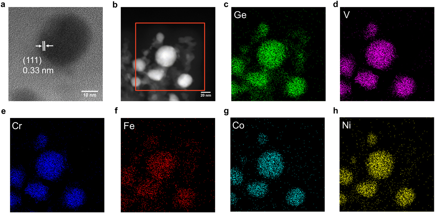 | ||
| Fig. 2 TEM and EDX analysis of the FeCoNiCrVGe HEG. (a) A representative high-resolution image showing characteristic (111) lattice spacing. (b) A representative HAADF-STEM image and (c)–(h) corresponding EDX mapping of the indicated elements. | ||
In situ analysis of HEG formation
To gain a more complete understanding of the processes leading to the transformation of HEA NPs@GeNSs to an AuAgCuPdPtGe HEG we performed in situ heating XRD experiments. These experiments captured the diffraction pattern of the HEA NPs@GeNSs from room temperature to 800 °C (Fig. S16a, ESI†). A dome (Fig. S17a, ESI†) was used to maintain an inert N2 atmosphere during the heating process and its background contribution (Fig. S17b, ESI†) was subtracted from the resulting XRD diffraction pattern. During the heating process, a gradual decrease in the intensity of the (006) reflection of GeNSs (15.5°) was noted at 200 °C, followed by complete disappearance at 300 °C, suggesting the GeNS decomposition.41 At and above 300 °C, broad reflections characteristic of the cubic Ge crystal structure emerged, signifying the formation of nanosized Ge. With increased temperature these reflections narrowed indicative of increasing crystallite size and structural ordering.46 Using Scherrer analyses,47 the average crystallite sizes were determined from the XRD patterns providing an increase in average crystallite size from 1.6 to 61.8 nm as the annealing temperature increased from 300 to 800 °C (Fig. S18a, ESI†). Additionally, the appearance of sharp intense reflections corresponding to hexagonal GeO2 was observed after 700 °C. This observation is consistent with the crystallization of surface Ge oxide species at high temperatures39 and is in agreement with previous ex situ XRD analyses. During heating these GeO2-related features shifted to lower angles due to thermal expansion at high temperture48 and shifted back to their original positions after cooling.For comparison, the formation of the FeCoNiCrVGe HEG was also investigated by in situ heating XRD. The XRD patterns of FeCoNiCrVGe HEG during the heating process from room temperature to 800 °C (Fig. S16b, ESI†) showed a similar evolution to that observed for the formation of AuAgCuPdPtGe HEG. The reflection assigned to GeNSs at 15.5° also decreased at 200 °C and disappeared at 300 °C, indicating the decomposition of GeNSs occurred at 200 °C and completed at 300 °C,41 just as observed in the case of AuAgCuPdPtGe HEG. Furthermore, broad intensity peaks corresponding to a cubic Ge crystal structure appeared at 400 °C. As the temperature increased, these reflections became sharpened, indicating an increase in crystallite size and structural ordering, similar to the behavior observed in the AuAgCuPdPtGe HEG transformation. Using the Scherrer equation, the average crystallite sizes were calculated from the XRD patterns and showed an increase from 2.2 to 55.3 nm as the annealing temperature increased from 300 to 800 °C (Fig. S18a, ESI†). While the AuAgCuPdPtGe HEG displayed reflections arising from hexagonal GeO2 with higher intensities at 700 °C, it is important to note that the FeCoNiCrVGe HEG showed these reflections with much lower intensities at 800 °C. This suggests that more GeNSs remained unreacted with the transition metal salts (i.e., FeCl3, VCl3, CrCl2, CoCl2, NiCl2) and the formation of hexagonal GeO2 originated from trace surface oxidation of GeNSs (Fig. S19, ESI†).
To monitor the structural evolution of FeCoNiCrVGe HEG in real time, in situ heating STEM experiments were performed; a representative movie is presented in Movie S1 (ESI†). The HAADF-STEM images of the same location (Fig. 3) captured the morphological changes of GeNSs upon heating from room temperature to 800 °C and ultimately leading to the formation of the FeCoNiCrVGe HEG. There was no obvious change observed in the GeNS below 300 °C, consistent with this initial heating stage primarily involving the breaking of Ge–H bonds, with hydrogen radicals subsequently reducing the metal salts to form metal atoms. Above 300 °C, GeNS began decomposing into Ge, resulting in the formation of small grains, while metal atoms diffused into the structure.49,50 Notably, the grain size increases slowly below 600 °C, but grows rapidly at 600 °C and above. The TEM particle sizes (Fig. S18b, ESI†) measured during the heating process showed an increase from 1.3 to 53.3 nm, which is in agreement with the previous in situ heating XRD results. Observations from the contrast-enhanced images (Fig. S20, ESI†) revealed the presence of small nanoparticles around the germanide at 700 °C, which grew larger at 800 °C. These nanoparticles resulted from the reduction of excess metal salts on the in situ heating nanochip instead the GeNS. EDX mapping (Fig. S21, ESI†) further confirmed the morphology of GeNSs in HAADF-STEM and revealed the presence of the five target metal salts before heating. After heating, EDX mapping (Fig. S23, ESI†) indicated the co-localization of morphological features characteristic of FeCoNiCrVGe HEG. The EDX spectrum (Fig. S22 and S24, ESI†) showed a notable decrease in the Cl signal (i.e., from 3.43 to 0.05 atomic %), while signals corresponding to Ge and the other five metal signals remained around 3 atomic % after heating. This finding suggests a successful transformation from metal salts&GeNS precursor to the FeCoNiCrVGe HEG.
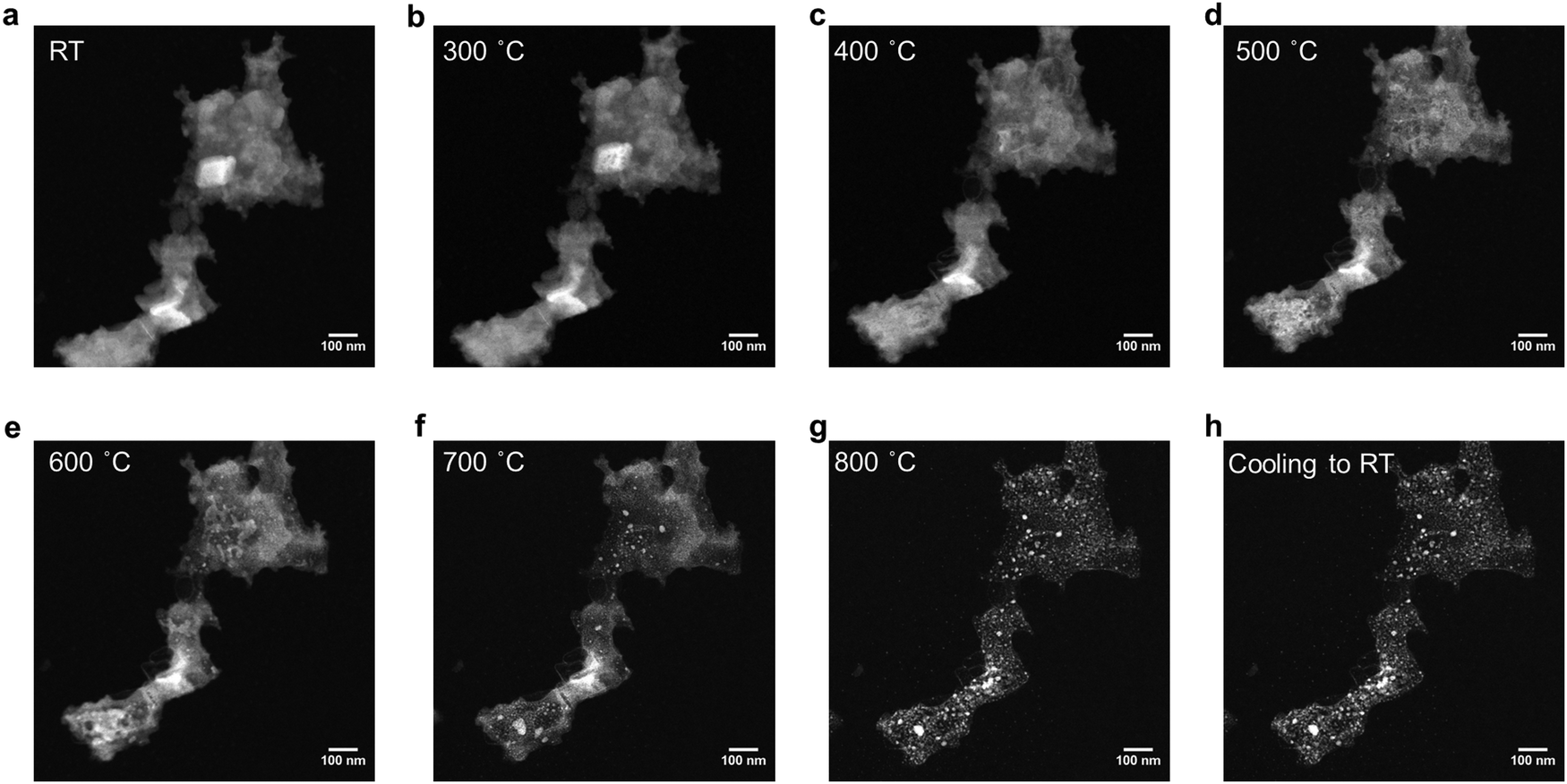 | ||
| Fig. 3 HAADF-STEM images of FeCoNiCrVGe HEG at the same location during the in situ heating experiment from room temperature to 800 °C (a)–(g) and after cooling down to room temperature (h). The sample slightly shifted due to the thermal drift. | ||
To provide a comparison, the transformation process of HEA NPs@GeNSs to AuAgCuPdPtGe HEG was also investigated using in situ heating STEM experiments, as presented in Movie S2 (ESI†). The HAADF-STEM images of the same location (Fig. S25, ESI†) showed the morphology evolution of the nanosheets as they were heated from room temperature to 800 °C. Below 300 °C, no significant morphological changes were observed, indicating a similar initial stage involving the breakage of Ge–H bonds. After 300 °C, it became challenging to observe the transformation of underlying GeNSs to Ge since they were covered by the HEA NPs. Instead, the surface HEA NPs were observed to disappear, suggesting that they diffused into the underlying Ge. Above 600 °C, the fast growth of larger particles from the small grains was observed. The sizes of the particles measured from the TEM (Fig. S18b, ESI†) also showed a slower growth stage before 600 °C, followed by a faster growth stage after 600 °C, consistent with previous in situ XRD results. Unlike the FeCoNiCrVGe HEG, no obvious nanoparticles were observed around the nanosheets, consistent with the transformation in this case primarily involves the diffusion of HEA NPs into the Ge. The EDX mapping and spectrum (Fig. S26 and S27, ESI†) further confirmed the morphology of HEA NPs@GeNSs in HAADF-STEM, which comprised the HEA NPs before heating.35 After heating the EDX mapping and spectrum (Fig. S28 and S29, ESI†) showed co-localization of morphological features of AuAgCuPdPtGe HEG nanoparticles.
Conclusions
The present study has successfully demonstrated a method for preparing two types of high-entropy germanides (Au0.54Ag0.53Cu0.55Pd0.55Pt0.53Ge and Fe0.63Co0.62Ni0.64Cr0.63V0.61Ge) using a rapid thermal annealing. HEG formation was verified by XRD and XPS, which provided evidence of their structure and elemental composition/oxidation states, respectively. Transmission electron microscopy further revealed that the HEGs possessed a near equal concentrations of all the constituent elements and exhibited a homogenous distribution throughout the material. The transformation processes were subsequently investigated by in situ heating in XRD and STEM. HEG formation involved the decomposition of GeNSs during the initial stages, followed by a slow grain growth process through atom diffusion at temperatures below 600 °C, and finally a rapid grain growth process at higher temperatures. These findings provide valuable insights into the formation and growth mechanisms of HEGs. The ability to synthesize and characterize these HEGs paves the way for future investigations into their unique properties and potential applications in fields such as materials science, electronics, and catalysis.Experimental
Materials
Germanium (Ge, 99.999%), calcium (Ca, 99.0%), gold(III) chloride (AuCl3, 99.99%), silver nitrate (AgNO3, 99.9999%), copper(II) chloride (CuCl2, 99.999%), palladium(II) chloride (PdCl2, 99.9%) and platinum(IV) chloride (PtCl4, 99.999%) were purchased from Sigma-Aldrich and hydrochloric acid (HCl, 37% w/w), ethanol (anhydrous), isopropyl alcohol (anhydrous), acetone (HPLC grade) and toluene (HPLC grade) were purchased from Fisher Scientific. Milli-Q (18.2 MΩ cm at 25 °C) water was used for all experiments. All organic solvents were dried using an Innovative Technology, Inc. Grubbs-type solvent purification system.Synthesis of CaGe2
A stoichiometric mixture of calcium and germanium metals was pressed into a pellet and subsequently melted together from both sides using an arc furnace.37Synthesis of stacked germanane
Germanane was prepared via topotactic deintercalation of calcium ions from CaGe2 using modified literature procedure.42 Briefly, 0.3 g (2.7 mmol) of freshly prepared granular CaGe2 was loaded into Schlenk flask that was charged with concentrated aqueous HCl (30 mL) that had been cooled to −30 °C. The reaction mixture was maintained at −30 °C for at least 7 days and agitated at regular intervals. Subsequently, the reaction mixture was filtered using a glass frit under nitrogen to provide grey flakes that exhibited a metallic sheen that were washed three times with ice-cold Milli-Q water and anhydrous ethanol. The resulting shiny grey solid was dried in vacuo on the Schlenk line and stored in a nitrogen-filled glovebox and subdued light until further use.Preparation of high-entropy nanoparticles-decorated germanium nanosheets (HEA NPs@GeNSs)
To prepare high entropy alloy nanoparticles-decorated germanium nanosheets (HEA NPs@GeNSs; HEA = Au, Ag, Cu, Pt, Pd), germanane powder (73 mg; 1 mmol) was dispersed in 4 mL Milli-Q water. The mixture was sonicated in a bath sonicator for 2 hours to yield a red suspension of exfoliated GeNSs. Subsequently, an appropriate mass (0.01 mmol) of the anhydrous metal salt in question (AuCl3, AgNO3, CuCl2, PdCl2 and PtCl4) was dissolved in 1 mL of Milli-Q water together. The metal salt solution (i.e., 0.1 mL) was then added into the GeNS dispersion at room temperature in subdued light and the original red suspensions turned black. The mixture was stirred for 10 min and the product was recovered by centrifugation and washed with Milli-Q water three times. The product was dried for 12 h in vacuo and subsequently stored in nitrogen filled glovebox and subdued light. Typical mass yields for this procedure were 55 mg. The resulting material was characterized using XRD, XPS, and TEM.Synthesis of AuAgCuPdPtGe HEG
The above prepared HEA@GeNSs (0.5 g) was heated up to 800 °C at 1 °C s−1 under Ar flow in a tube furnace. After reaching the peak temperature, the sample was maintained at that temperature for 10 min and quenched to room temperature by removing the tube from the furnace and blowing the tube with constant N2 gas. Upon cooling to room temperature, the resulting black solid was subsequently stored in nitrogen filled glovebox. Typical mass yields for this procedure were 100 mg. The resulting material was characterized using XRD, XPS, and TEM.Synthesis of FeCoNiCrVGe HEG
To prepare FeCoNiCrVGe HEG, germanane powder (73 mg; 1 mmol) was dispersed in 4 mL anhydrous ethanol. The mixture was sonicated in a bath sonicator for 2 hours to yield a red suspension of exfoliated GeNSs. Subsequently, an appropriate mass (0.1 mmol) of the anhydrous metal salt in question (FeCl3, CoCl2, NiCl2, CrCl2 and VCl3) was dissolved in 1 mL of anhydrous ethanol together. The metal salt solution (i.e., 1 mL) was then added into the GeNS dispersion while stirring at room temperature. The solvent was evaporated at 50 °C for 10 min using a Heidolph G5 rotary evaporator. The resulting slurry was heated up to 800 °C at 1 °C s−1 under Ar flow in a tube furnace. After reaching the peak temperature, the sample was maintained at that temperature for 10 min and quenched to room temperature by removing the tube from the furnace and blowing the tube with constant N2 gas. Upon cooling to room temperature, the resulting black solid was subsequently stored in nitrogen filled glovebox. The resulting material was characterized using XRD, XPS, and TEM.Characterization
Electron microscopy
Transmission electron microscopy (TEM) bright and dark field images were acquired using a JEOL JEM-ARM200CF S/TEM electron microscope at an accelerating voltage of 200 kV. High resolution (HR) TEM images were processed using Gatan Digital Micrograph software (Version 3.4.1). TEM samples were prepared by depositing a drop of a dilute toluene suspension of the sample in question onto a holey or ultra-thin carbon coated copper or molybdenum grid (obtained from Electron Microscopy Inc.). The grid bearing the sample was kept in a vacuum chamber at a base pressure of 0.2 bar for at least 24 h prior to data collection. The particles size distribution was assembled as an average shifted histogram as described by Buriak et al. for at least 300 particles in TEM.51In situ heating TEM experiments were conducted using the DENSsolutions Wildfire in situ heating TEM sample holder. TEM samples were prepared by depositing a drop (5 μL) of a dilute ethanol suspension of metal salts and GeNSs onto a DENSsolutions Wildfire Si3N4 nano-chip. The heating program was monitored by DENSsolutions Impulse software. After collecting the images and EDX mapping at room temperature, the samples were heated up to 800 °C at 1 °C s−1 and kept at 800 °C for 10 min. Then the samples were cooled down to room temperature at 20 °C s−1.
X-ray photoelectron spectroscopy (XPS)
XPS analyses were performed using a Kratos Axis Ultra instrument operating in energy spectrum mode at 210 W. The base and operating chamber pressure were maintained at 10−7 Pa. A monochromatic Al Kα source (λ = 8.34 Å) was used to irradiate the samples, and the spectra were obtained with an electron take-off angle of 90°. CasaXPS software (VAMAS) was used to interpret high-resolution spectra. All spectra were internally calibrated to the C 1s emission (284.8 eV) of adventitious carbon. After calibration, a Shirley-type background was applied to remove most of the extrinsic loss structure. The Ge 3d region were deconvoluted into the Ge 3d5/2 and 3d3/2 spin–orbit couple for the element Ge and the energy separation of these doublets was fixed at 0.58 eV and the Ge 3d3/2 to 3d5/2 area was fixed at 0.67.37 For the high-resolution XP spectra of metals, the spin–orbit couple energy separation and area were fixed and the spectral envelope was fit using a Lorentzian asymmetric line shape LA(a, b, n) where a and b define the asymmetry and n defines the Gaussian width. The various spectral regions were fit as follows: Au 4f was deconvoluted into the Au 4f7/2 and 4f5/2 spin–orbit couple and the energy separation of these doublets was fixed at 3.70 eV and the Au 4f5/2 to 4f7/2 area ratio was fixed at 0.75.52 Ag 3d was deconvoluted into the Ag 3d5/2 and 3d3/2 spin–orbit couple and the energy separation of these doublets was fixed at 6.00 eV and the Ag 3d3/2 to 3d5/2 area ration was fixed at 0.67.53 Cu 2p was deconvoluted into the Cu 2p3/2 and 2p1/2 spin–orbit couple and the energy separation of these doublets was fixed at 19.75 eV and the Cu 2p1/2 and 2p3/2 area ratio was fixed at 0.50.54 Pd 3d was deconvoluted into the Pd 3d5/2 and 3d3/2 spin–orbit couple and the energy separation of these doublets was fixed at 5.26 eV and the Pd 3d3/2 to 3d5/2 area ratio was fixed at 0.67.55 Pt 4f was deconvoluted into the Pt 4f7/2 and 4f5/2 spin–orbit couple and the energy separation of these doublets was fixed at 3.35 eV and the Pt 4f5/2 to 4f7/2 area ratio was fixed at 0.75.56 Fe 2p was deconvoluted into the Fe 2p3/2 and 2p1/2 spin–orbit couple and the energy separation of these doublets was fixed at 13.1 eV and the Fe 2p1/2 and 2p3/2 area ratio was fixed at 0.50. Co 2p was deconvoluted into the Co 2p3/2 and 2p1/2 spin–orbit couple and the energy separation of these doublets was fixed at 14.99 eV and the Co 2p1/2 and 2p3/2 area ratio was fixed at 0.50. Ni 2p was deconvoluted into the Ni 2p3/2 and 2p1/2 spin–orbit couple and the energy separation of these doublets was fixed at 17.3 eV and the Ni 2p1/2 and 2p3/2 area ratio was fixed at 0.50. Cr 2p was deconvoluted into the Cr 2p3/2 and 2p1/2 spin–orbit couple and the energy separation of these doublets was fixed at 9.3 eV and the Cr 2p1/2 and 2p3/2 area ratio was fixed at 0.50. V 2p was deconvoluted into the V 2p3/2 and 2p1/2 spin–orbit couple and the energy separation of these doublets was fixed at 7.6 eV and the V 2p1/2 and 2p3/2 area ratio was fixed at 0.50.57Powder X-ray diffraction (XRD) analysis
XRD was performed using a Bruker D8 Advance diffractometer (Cu-Kα1 (λ = 1.5406 Å) and Kα2 (λ = 1.5444 Å) radiation). Samples were prepared by mounting the powder in question on a zero background Si crystal sample holder. XRD patterns were scanned between 2θ ranges of 10–80° with a scan step of 0.06°/s. The instrumental broadening effect was considered by measuring a NIST LaB6 standard sample with a same scanning speed. Jade 6 was used to fit the peak broadening with both size and strain effect. The lattice parameter for the AuAgCuPdPtGe HEG and FeCoNiCrVGe HEG was calculated using the lattice parameter of the AuAgCuPdPt and FeCoNiCrV HEA and the lattice parameter of Ge based on Vegard's Law.| aHEA(1−x)Gex = (1 − x)aHEA(1−x) + xaGex |
In situ XRD experiments were performed using a Bruker D8 Discover diffractometer (Cu-Kα1 (λ = 1.5406 Å) and Kα2 (λ = 1.5444 Å) radiation) with an Anton Paar DHS 1100 heating stage. Samples were prepared by mounting the powder in question on a zero background Si crystal sample holder. The samples were heated up to 800 °C at 1 °C s−1 under N2 flow inside the dome of the heating stage and kept at each desired temperature (200 °C, 300 °C, 400 °C, 500 °C, 600 °C, 700 °C, 750 °C and 800 °C) for XRD measurement. XRD patterns were scanned between 2θ ranges of 10–80° with a scan step of 0.06° s−1 and subtracted the background from the dome measured at room temperature. After finishing the heating program, the samples were cooled to room temperature by circulating the dome with N2 flow.
Author contributions
Chuyi Ni: conceptualization, methodology, investigation, formal analysis, investigation, data curation, and writing – original draft. Kevin M. O’Connor: investigation, data curation, and writing – review & editing. Cole Butler: investigation, data curation, and writing – review & editing. Jonathan G. C. Veinot: supervision, conceptualization, methodology, formal analysis, investigation, data curation, resources, funding acquisition, and writing – review & editing. All authors discussed the results and the implications of this manuscript. All authors have given approval to the final version of the manuscript.Conflicts of interest
There are no conflicts to declare.Acknowledgements
The authors recognize the continued generous funding from the Natural Science and Engineering Research Council (NSERC Discovery Grant program; RGPIN-2020-04045), the ATUMS training program supported by NSERC CREATE (CREATE-463990-2015) as well as the University of Alberta Faculties of Science and Graduate Studies, and Alberta Innovates Strategic Projects Program. We also thank the staff at Analytical and Instrumentation Laboratory in the Department of Chemistry at the University of Alberta for the assistance with FTIR analysis, and the University of Alberta Nanofab for support in collecting XPS data.References
- Y. Yao, Q. Dong, A. Brozena, J. Luo, J. Miao, M. Chi, C. Wang, I. G. Kevrekidis, Z. J. Ren, J. Greeley, G. Wang, A. Anapolsky and L. Hu, Science, 2022, 376, abn3103 CrossRef PubMed.
- M. W. Glasscott, A. D. Pendergast, S. Goines, A. R. Bishop, A. T. Hoang, C. Renault and J. E. Dick, Nat. Commun., 2019, 10, 2650 CrossRef PubMed.
- Y. Yao, Z. Huang, P. Xie, S. D. Lacey, R. J. Jacob, H. Xie, F. Chen, A. Nie, T. Pu, M. Rehwoldt, D. Yu, M. R. Zachariah, C. Wang, R. Shahbazian-Yassar, J. Li and L. Hu, Science, 2018, 359, 1489–1494 CrossRef CAS PubMed.
- P.-C. Chen, X. Liu, J. L. Hedrick, Z. Xie, S. Wang, Q.-Y. Lin, M. C. Hersam, V. P. Dravid and C. A. Mirkin, Science, 2016, 352, 1565–1569 CrossRef CAS PubMed.
- N. Kumar, C. S. Tiwary and K. Biswas, J. Mater. Sci., 2018, 53, 13411–13423 CrossRef CAS.
- S. Gao, S. Hao, Z. Huang, Y. Yuan, S. Han, L. Lei, X. Zhang, R. Shahbazian-Yassar and J. Lu, Nat. Commun., 2020, 11, 2016 CrossRef CAS PubMed.
- K. Mori, N. Hashimoto, N. Kamiuchi, H. Yoshida, H. Kobayashi and H. Yamashita, Nat. Commun., 2021, 12, 3884 CrossRef CAS PubMed.
- H. Qiao, M. T. Saray, X. Wang, S. Xu, G. Chen, Z. Huang, C. Chen, G. Zhong, Q. Dong, M. Hong, H. Xie, R. Shahbazian-Yassar and L. Hu, ACS Nano, 2021, 15, 14928–14937 CrossRef CAS PubMed.
- G. Zhu, Y. Jiang, H. Yang, H. Wang, Y. Fang, L. Wang, M. Xie, P. Qiu and W. Luo, Adv. Mater., 2022, 34, e2110128 CrossRef PubMed.
- G. Cao, J. Liang, Z. Guo, K. Yang, G. Wang, H. Wang, X. Wan, Z. Li, Y. Bai, Y. Zhang, J. Liu, Y. Feng, Z. Zheng, C. Lu, G. He, Z. Xiong, Z. Liu, S. Chen, Y. Guo, M. Zeng, J. Lin and L. Fu, Nature, 2023, 619, 73–77 CrossRef CAS PubMed.
- N. Hashimoto, K. Mori and H. Yamashita, J. Phys. Chem. C, 2023, 127, 20786–20793 CrossRef CAS.
- N. Kar, M. McCoy, J. Wolfe, S. L. A. Bueno, I. H. Shafei and S. E. Skrabalak, Nat. Synth., 2024, 3, 175–184 CrossRef.
- Y. Kang, O. Cretu, J. Kikkawa, K. Kimoto, H. Nara, A. S. Nugraha, H. Kawamoto, M. Eguchi, T. Liao, Z. Sun, T. Asahi and Y. Yamauchi, Nat. Commun., 2023, 14, 4182 CrossRef CAS PubMed.
- A. Sarkar, L. Velasco, D. Wang, Q. Wang, G. Talasila, L. de Biasi, C. Kubel, T. Brezesinski, S. S. Bhattacharya, H. Hahn and B. Breitung, Nat. Commun., 2018, 9, 3400 CrossRef PubMed.
- T. Wang, H. Chen, Z. Yang, J. Liang and S. Dai, J. Am. Chem. Soc., 2020, 142, 4550–4554 CrossRef CAS PubMed.
- C. R. McCormick and R. E. Schaak, J. Am. Chem. Soc., 2021, 143, 1017–1023 CrossRef CAS PubMed.
- J. Sure, D. Sri Maha Vishnu, H. K. Kim and C. Schwandt, Angew. Chem., Int. Ed., 2020, 59, 11830–11835 CrossRef CAS PubMed.
- T. Jin, X. Sang, R. R. Unocic, R. T. Kinch, X. Liu, J. Hu, H. Liu and S. Dai, Adv. Mater., 2018, 30, e1707512 CrossRef PubMed.
- G. Yi, Y. Ding, Y. Cheng, P. Zhang, X. Wang and X. Liang, J. Alloys Compd., 2022, 916, 165384 CrossRef CAS.
- S. Dong, Q. Li, H. Hu, X. Zhang, Y. Li, K. Ye, W. Hou, J. He and H. Zhao, Appl. Surf. Sci., 2023, 615, 156413 CrossRef CAS.
- S. S. Soliman, G. R. Dey, C. R. McCormick and R. E. Schaak, ACS Nano, 2023, 17, 16147–16159 CrossRef CAS PubMed.
- M. C. Folgueras, Y. Jiang, J. Jin and P. Yang, Nature, 2023, 621, 282–288 CrossRef CAS PubMed.
- X. L. Shi, J. Zou and Z. G. Chen, Chem. Rev., 2020, 120, 7399–7515 CrossRef CAS PubMed.
- M. A. Rabie, S. Mirza, Y. Hu and Y. M. Haddara, J. Mater. Sci.: Mater. Electron., 2019, 30, 10031–10063 CrossRef CAS.
- T. Götsch, M. Stöger-Pollach, R. Thalinger and S. Penner, J. Phys. Chem. C, 2014, 118, 17810–17818 CrossRef.
- D. D. Vaughn, D. Sun, J. A. Moyer, A. J. Biacchi, R. Misra, P. Schiffer and R. E. Schaak, Chem. Mater., 2013, 25, 4396–4401 CrossRef.
- C. Yan, J. M. Higgins, M. S. Faber, P. S. Lee and S. Jin, ACS Nano, 2011, 5, 5006–5014 CrossRef CAS PubMed.
- H. Yoon, K. Seo, N. Bagkar, J. In, J. Park, J. Kim and B. Kim, Adv. Mater., 2009, 21, 4979–4982 CrossRef CAS PubMed.
- W. Peng, S. Chanakian and A. Zevalkink, Inorg. Chem. Front., 2018, 5, 1744–1759 RSC.
- H. Yoon, T. Kang, J. M. Lee, S.-I. Kim, K. Seo, J. Kim, W. I. Park and B. Kim, J. Phys. Chem. Lett., 2011, 2, 956–960 CrossRef CAS.
- J. Tang, C.-Y. Wang, F. Xiu, M. Lang, L.-W. Chu, C.-J. Tsai, Y.-L. Chueh, L.-J. Chen and K. L. Wang, ACS Nano, 2011, 5, 6008–6015 CrossRef CAS PubMed.
- J. Mao, H. S. Kim, J. Shuai, Z. Liu, R. He, U. Saparamadu, F. Tian, W. Liu and Z. Ren, Acta Mater., 2016, 103, 633–642 CrossRef CAS.
- R. Z. Zhang, F. Gucci, H. Zhu, K. Chen and M. J. Reece, Inorg. Chem., 2018, 57, 13027–13033 CrossRef CAS PubMed.
- Z. Fan, H. Wang, Y. Wu, X. J. Liu and Z. P. Lu, RSC Adv., 2016, 6, 52164–52170 RSC.
- C. Ni, K. M. O'Connor, J. Trach, C. Butler, B. Rieger and J. G. C. Veinot, Nanoscale Horiz., 2023, 8, 1217–1225 RSC.
- B. Song, Y. Yang, M. Rabbani, T. T. Yang, K. He, X. Hu, Y. Yuan, P. Ghildiyal, V. P. Dravid, M. R. Zachariah, W. A. Saidi, Y. Liu and R. Shahbazian-Yassar, ACS Nano, 2020, 14, 15131–15143 CrossRef CAS PubMed.
- H. Yu, A. N. Thiessen, M. A. Hossain, M. J. Kloberg, B. Rieger and J. G. C. Veinot, Chem. Mater., 2020, 32, 4536–4543 CrossRef CAS.
- S. Mukherjee, A. Nag, V. Kocevski, P. K. Santra, M. Balasubramanian, S. Chattopadhyay, T. Shibata, F. Schaefers, J. Rusz, C. Gerard, O. Eriksson, C. U. Segre and D. D. Sarma, Phys. Rev. B: Condens. Matter Mater. Phys., 2014, 89, 224105 CrossRef.
- P. G. Nalam, D. Das, S. Tan and C. V. Ramana, ACS Appl. Electron. Mater., 2022, 4, 3115–3124 CrossRef CAS.
- U. Holzwarth and N. Gibson, Nat. Nanotechnol., 2011, 6, 534 CrossRef CAS PubMed.
- E. Bianco, S. Butler, S. Jiang, O. D. Restrepo, W. Windl and J. E. Goldberger, ACS Nano, 2013, 7, 4414–4421 CrossRef CAS PubMed.
- H. Yu, T. Helbich, L. M. Scherf, J. Chen, K. Cui, T. F. Fässler, B. Rieger and J. G. C. Veinot, Chem. Mater., 2018, 30, 2274–2280 CrossRef CAS.
- S. L. A. Bueno, A. Leonardi, N. Kar, K. Chatterjee, X. Zhan, C. Chen, Z. Wang, M. Engel, V. Fung and S. E. Skrabalak, ACS Nano, 2022, 16, 18873–18885 CrossRef CAS PubMed.
- E. M. Smith, W. H. Streyer, N. Nader, S. Vangala, G. Grzybowski, R. Soref, D. Wasserman and J. W. Cleary, Opt. Mater. Express, 2018, 8, 968–982 CrossRef CAS.
- M. Beekman, S. M. Kauzlarich, L. Doherty and G. S. Nolas, Materials, 2019, 12, 1139 CrossRef CAS PubMed.
- L. Su, X. Chen, L. Xu, T. Eldred, J. Smith, C. DellaRova, H. Wang and W. Gao, ACS Nano, 2022, 16, 21397–21406 CrossRef CAS PubMed.
- A. L. Patterson, Phys. Rev., 1939, 56, 978–982 CrossRef CAS.
- Y. Okada and Y. Tokumaru, J. Appl. Phys., 1984, 56, 314–320 CrossRef CAS.
- K. El Hajraoui, M. A. Luong, E. Robin, F. Brunbauer, C. Zeiner, A. Lugstein, P. Gentile, J. L. Rouviere and M. Den Hertog, Nano Lett., 2019, 19, 2897–2904 CrossRef CAS PubMed.
- K. El Hajraoui, E. Robin, C. Zeiner, A. Lugstein, S. Kodjikian, J. L. Rouviere and M. Den Hertog, Nano Lett., 2019, 19, 8365–8371 CrossRef CAS PubMed.
- S. L. Anderson, E. J. Luber, B. C. Olsen and J. M. Buriak, Chem. Mater., 2016, 28, 5973–5975 CrossRef CAS.
- Y. Zhang, X. Han, R. Liu, Y. Liu, H. Huang, J. Zhang, H. Yu and Z. Kang, J. Phys. Chem. C, 2012, 116, 20363–20367 CrossRef CAS.
- L. Ma, l Jia, X. Guo and L. Xiang, Chin. J. Catal., 2014, 35, 108–119 CrossRef CAS.
- M. C. Biesinger, Surf. Interface Anal., 2017, 49, 1325–1334 CrossRef CAS.
- M. C. Militello and S. J. Simko, Surf. Sci. Spectra, 1994, 3, 387–394 CrossRef CAS.
- C. R. O’Connor, M. A. Van Spronsen, M. Karatok, J. Boscoboinik, C. M. Friend and M. M. Montemore, J. Phys. Chem. C, 2021, 125, 10685–10692 CrossRef.
- G. Silversmit, D. Depla, H. Poelman, G. B. Marin and R. De Gryse, J. Electron Spectrosc. Relat. Phenom., 2004, 135, 167–175 CrossRef CAS.
Footnote |
| † Electronic supplementary information (ESI) available. See DOI: https://doi.org/10.1039/d4nh00012a |
| This journal is © The Royal Society of Chemistry 2024 |