
 Open Access Article
 This Open Access Article is licensed under a Creative Commons Attribution-Non Commercial 3.0 Unported Licence
Fabrication of nanoparticle array membranes by integrating semi-crystalline polymer self-assembly with NIPS for water treatment†
Yu
Ma
 ab,
Xiaoli
Zhao
*c and
Bin
He
*ab
ab,
Xiaoli
Zhao
*c and
Bin
He
*ab
aGuangdong Key Laboratory of Integrated Agro-environmental Pollution Control and Management, Guangdong Institute of Eco-environmental Science & Technology, Guangzhou, 510650, China. E-mail: bhe@soil.gd.cn
bNational-Regional Joint Engineering Research Center for Soil Pollution Control and Remediation in South China, Guangzhou, 510650, China
cState Key Laboratory of Environmental Criteria and Risk Assessment, Chinese Research Academy of Environmental Sciences, Beijing, 100012, China
First published on 20th May 2024
Abstract
The integration of polymer self-assembly with non-solvent induced phase separation (SNIPS) represents a recent advancement in membrane fabrication. This breakthrough allows for the fabrication of membranes with uniformly sized pores, enabling precise and fast separation through a phase inversion process commonly used in industrial fabrication. Currently, block copolymers are used in implementing the SNIPS strategy. In order to facilitate an easier and more flexible fabrication procedure, we employed the widely used semi-crystalline polymer polyvinylidene fluoride (PVDF) as the base material for achieving SNIPS through self-seeding. This process involves filtering the PVDF casting solution to induce microphase separation and generate crystal seeds. Subsequently, NIPS is applied to enable the growth of crystal seeds into uniformly distributed nanoparticles with consistent size and shape, ultimately resulting in a membrane with a uniform pore size. The fabricated membrane exhibited improved flux (2924.67 ± 28.02 L m−2 h−1 at 0.5 bar) and rejection (91% for 500 nm polystyrene particles). Notably, the microphase separation in the casting solution is a distinguishing feature of the SNIPS compared to NIPS. In this study, we found that the microphase separation of semi-crystalline polymers is also crucial for achieving membranes with uniform pore sizes. This finding may extend the potential application of the SNIPS strategy to include semi-crystalline polymers.
Introduction
Membrane separation has played a significant role in modern chemical engineering due to its superior energy efficiency.1,2 However, traditional membranes, typically prepared using NIPS or thermal induced phase separation, commonly encounter the issue of broad size distribution.3,4 These problems significantly contribute to the trade-off effect observed in membrane separation and are therefore important factors to consider.2,5 To address these issues, researchers have developed isoporous (or homoporous) membranes with uniformly sized pores. These membranes, both organic and inorganic, can be effectively prepared using various techniques such as self-assembly of block copolymers, anodization, and micro-electromechanical systems (MEMS), among others.6–10 Compared to other methods, membrane integration of polymer self-assembly with non-solvent induced phase separation (SNIPS) is a novel strategy.11–16 This technique readily generates isopores through a phase inversion process commonly used in industrial fabrication. Due to this compatibility with existing industrial membrane production processes, SNIPS allows for the production of isoporous membranes without the need to modify or upgrade existing manufacturing facilities.11Currently, block copolymers are used as the material for implementing the SNIPS strategy due to their exceptional ability to self-assemble into periodic nanostructures, which can be utilized to create uniform channels.11,16,17 However, in order to facilitate an easier and more flexible fabrication process for high-performance membranes using the SNIPS strategy, it is necessary to explore alternative polymers that are more commonly available in addition to block copolymers. Self-seeding is a process that harnesses the thermodynamic properties of semi-crystalline polymers to achieve the self-assembly of a series of polymers with uniform size, shape, and orientation.18–20 By partially dissolving or melting the semi-crystalline polymer, numerous single crystals can be formed. Under suitable conditions, such as reduced polymer mobility through concentration or cooling, these single crystals, known as crystal seeds, can undergo growth and transform into larger semi-crystalline polymers while maintaining a uniform orientation, morphology, and size.19–21 Therefore, integrating semi-crystalline polymer self-assembly with NIPS may also create membranes with uniform channels.
In this work, semi-crystalline polymer polyvinylidene difluoride (PVDF) was employed to fabricate nanoparticle array membranes with uniform pore sizes using the SNIPS strategy (Fig. 1). This meticulous control of pore sizes enhances membrane flux and enables effective removal of microplastic pollutants from wastewater. As a matter of fact, SNIPS refers in particular to the process that produces isoporous membranes from a polymer with phase inversion in non-solvents. Nunes et al. made the noteworthy discovery that the formation of isoporous membranes relies on the concentration of the solution being at or slightly lower than the critical point that triggers microphase separation of the block copolymer.22 Therefore, the microphase separation of polymers in casting solution is the landmark that distinguishes SNIPS from NIPS.11 In this study, we found that the microphase separation of semi-crystalline polymers is also crucial for the formation of membranes with a uniform pore size. This finding may expand the applicability of the SNIPS strategy to semi-crystalline polymers.
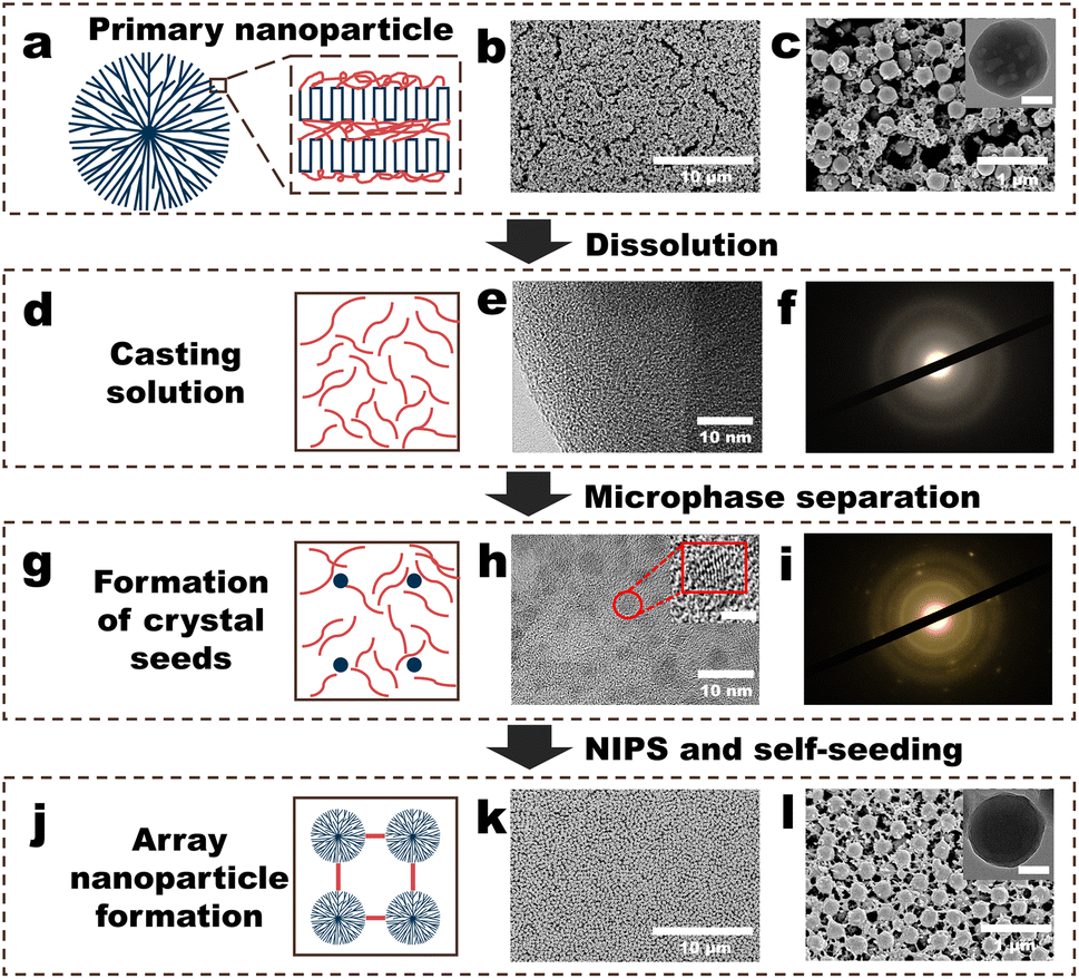 | ||
| Fig. 1 Fabrication procedure of the polyvinylidene fluoride (PVDF) nanoparticle (NP) array (NPs-A) membrane. (a) Schematic of the structure of a PVDF NP; (b and c) surface morphologies of the PVDF-NP aggregates (PVDF-NPs). Inset in (c) depicts the scanning transmission electron microscopy (STEM) image of a PVDF NP, and the scale bar is 100 nm; (d) schematic of the PVDF casting solution; (e) STEM image of a freeze-dried membrane made from a PVDF casting solution (PVDF-C membrane); (f) selected area electron diffraction (SAED) patterns of the PVDF-C membrane; (g) schematic of the formation of crystal seeds in PVDF casting solution; (h) STEM image of a freeze-dried membrane made from a PVDF-S (PVDF-S membrane); (i) SAED pattern of the PVDF-S membrane; (j) schematic of the formation of array nanoparticles in the NPs-A membrane; (k and l) surface morphologies of the NPs-A membrane. Inset in Fig. 1l shows the STEM image of a NP in the membrane, and the scale bar is 100 nm. | ||
Results and discussion
Fabrication procedure of the PVDF nanoparticle array (NPs-A) membrane
The membrane fabrication process began with the addition of a diluted polyvinylidene fluoride (PVDF) solution into water to obtain PVDF nanoparticles (PVDF-NPs) dispersed in water. This was followed by vacuum filtration of the PVDF-NP dispersions over a commercial microfiltration membrane to collect aggregates of PVDF-NPs. Subsequently, N,N-dimethylformamide (DMF) was filtered through these aggregates to partially dissolve them. This step resulted in a PVDF casting solution (PVDF-C) as illustrated in Fig. 1a–f. The PVDF-C then underwent further filtration to increase its concentration, leading to the formation of well-dispersed PVDF crystal seeds, denoted as PVDF-S, shown in Fig. 1g–i. Finally, by adding pure water to PVDF-S, a PVDF nanoparticle array (NPs-A) membrane was fabricated, as depicted in Fig. 1j–l.Addition of a diluted PVDF solution to water produced PVDF-NPs via phase inversion (Fig. 1a–c, S1–S2 and Video S1†). A significant Tyndall effect was observed upon laser illumination of the PVDF-NPs dispersed in water, indicating that the NPs exhibited colloidal properties and developed a highly dispersed heterogeneous system in water (Fig. S1 and Video S1†).23 The mechanism behind this method of PVDF-NP formation is NIPS. Traditionally, NIPS is defined as a phase-transition process where a polymer solvent and its non-solvent induce the transformation of the polymer into a porous separation membrane.4 However, when the amorphous polymer solution is diluted, the phase inversion process instead transforms the polymer into nanoscale particles.24 Further filtration of the dispersion to form PVDF-NP aggregates revealed that the aggregates were composed of homogeneous NPs (diameters: approximately 270 nm) and a lot of irregular polymers randomly distributed on the commercial (nylon) membrane surface (Fig. 1b and c). DMF was used to dissolve the PVDF-NP aggregates via vacuum filtration. The SEM image showed that the NPs and irregular polymers disappeared, and a PVDF-C membrane with a relatively smooth morphology was observed (Fig. S3†). STEM and selected area electron diffraction (SAED) analysis confirmed that the PVDF-C membrane exhibited a uniform structure (Fig. 1e), and crystal characteristics were not observed within the membrane (Fig. 1f). Further filtering the PVDF casting solution (PVDF-C) for 9 minutes, the SEM image showed that the surface morphology of the PVDF-S membrane was not obviously different from that of the PVDF-C membrane (Fig. S4†). However, STEM revealed that the microstructure of the PVDF-S membrane comprised numerous uniformly distributed, roughly round regions with diameters lower than 5 nm (Fig. 1h), and the lattice fringes observed in these regions indicated the presence of polymer crystals within the membrane (insets in Fig. 1h and S5†). In addition, the diffraction pattern exhibited a rectangular symmetry with well-defined spots, which clearly indicated the presence of single crystal (crystal seed) character (Fig. 1i). Thereafter, non-solvent (water) was filtered through PVDF-S for NIPS. An array of PVDF-NPs with a uniform size appeared on the membrane surface, and the NPs were connected by linear PVDF polymers, generating the NPs-A membrane; the NP diameter was approximately 270 nm, approximately the same as that of the initial NPs (Fig. 1k–l).
Morphologies of the membranes obtained through the fabrication procedure
Macroscopic morphologies and mechanical properties of PVDF-NP aggregates, PVDF-C membrane, PVDF-S membrane, and NPs-A membrane are shown in Fig. 2a–c and Videos S2, S3.† PVDF-NP aggregates quickly dispersed in water and transformed into a large amount of white powder, which could not form a membrane; in contrast, after being immersed in water, the PVDF-S membrane produced a thin membrane with flexibility; additionally, after being immersed in water, NPs-A5 formed a membrane with flexibility. This suggested good mechanical properties of the as-prepared NPs-A membrane.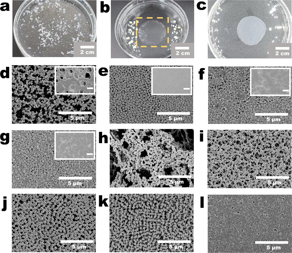 | ||
| Fig. 2 Morphologies of the membranes obtained through the fabrication procedure. (a) Digital image of the PVDF-NP aggregates in water; (b) digital image of the PVDF-S membrane in water; (c) digital image of the NPs-A membrane in water; (d–g) surface morphologies of (d) 9-NPs-A2, (e) 9-NPs-A8, (f) 9-NPs-A10, and (g) 9-NPs-A20 membrane. Insets in (d)–(g) show the surface morphologies of 9-PVDF-S2, 9-PVDF-S8, 9-PVDF-S10, and 9-PVDF-S20 membranes, respectively. The scale bars in these insets are 2 μm; (h) surface morphologies of the PVDF-PI membrane; (i–l) surface morphologies of (i) 0-NPs-A5, (j) 5-NPs-A5, (k) 14-NPs-A5, and (l) 30-NPs-A5 membranes. | ||
Microscopic morphologies of the membranes were investigated by adjusting the volume of the PVDF solution added to water during the initial nanoparticle formation stage (Fig. S1, S2† and Table 1). We found that under different conditions, the key points of membrane development were consistent. Particles and irregular polymers were observed on the commercial membrane surface when filtering nanoparticles (Fig. S6†), but the morphologies disappeared after filtering DMF (Fig. S3†) and subsequent microphase separation (inset in Fig. 2d–g and S4†); nevertheless, after the NIPS via water filtration, NPs and linear polymers reappeared (Fig. 2d–g and i–k). We also observed that under different conditions, the distributions of NPs on the 9-NPs-AX (X represents 0.5, 0.8, 1.0 and 2.0 mL) membrane surface were considerably different. When a small volume of the PVDF solution was added to water, the distributions of NPs on the 9-NPs-A2 membrane surface were not uniform, and many defects were present on the membrane surface (Fig. 2d). When a large volume of the PVDF solution was added to water, the distributions of NPs on the membrane surface were heterogeneous, and with an increase in the volume of the PVDF solution, this phenomenon became more significant (Fig. 2e–g).
| Membrane labelling | Membrane fabrication process | |||
|---|---|---|---|---|
| Volume of the PVDF solution (mL) | Vacuum filtration of the DMF | Filtration time of the PVDF-C (min) | NIPS | |
| PVDF-NPs5 | 0.5 | No | — | No |
| PVDF-NPs10 | 1.0 | No | — | No |
| PVDF-NPs20 | 2.0 | No | — | No |
| PVDF-C2 | 0.2 | Yes | 0 | No |
| PVDF-C5 | 0.5 | Yes | 0 | No |
| PVDF-C8 | 0.8 | Yes | 0 | No |
| PVDF-C10 | 1.0 | Yes | 0 | No |
| PVDF-C20 | 2.0 | Yes | 0 | No |
| 9-PVDF-S2 | 0.2 | Yes | 9 | No |
| 9-PVDF-S5 | 0.5 | Yes | 9 | No |
| 9-PVDF-S8 | 0.8 | Yes | 9 | No |
| 9-PVDF-S10 | 1.0 | Yes | 9 | No |
| 9-PVDF-S20 | 2.0 | Yes | 9 | No |
| 9-NPs-A2 | 0.2 | Yes | 9 | Yes |
| 9-NPs-A5 | 0.5 | Yes | 9 | Yes |
| 9-NPs-A8 | 0.8 | Yes | 9 | Yes |
| 9-NPs-A10 | 1.0 | Yes | 9 | Yes |
| 9-NPs-A20 | 2.0 | Yes | 9 | Yes |
| PVDF-PI | 0.5 | No | — | Yes |
| 0-NPs-A5 | 0.5 | Yes | 0 | Yes |
| 5-NPs-A5 | 0.5 | Yes | 5 | Yes |
| 14-NPs-A5 | 0.5 | Yes | 14 | Yes |
| 30-NPs-A5 | 0.5 | Yes | 30 | Yes |
Moreover, the microscopic morphologies of the membranes were investigated by selecting the methods of dissolving nanoparticle (NP) aggregates in DMF (the dissolution procedure shown in Fig. 1a and d). We found that direct dissolution of the NP aggregates in DMF ultimately leads to the fabrication of a PVDF phase-inversion (PVDF-PI) membrane, characterized by an uneven distribution of NPs and the existence of large-sized heterogeneous pore structures (Fig. 2h). Another method for dissolving NP aggregates was through DMF filtration, which resulted in the fabrication of a series of nanoparticle array (NPs-A) membranes. We observed that most of the NPs-A membranes exhibited increased uniformity compared to the PVDF-PI membrane, with the disappearance of large pore structures (Fig. 2e–g and i–k).
Applying the DMF filtration method, we further adjusted the filtration time of the PVDF casting solution (PVDF-C) (the microphase separation procedure shown in Fig. 1d, g and Table 1) to fabricate the Y-NPs-A5 (Y represents 0, 5, 9 and 14 minutes) membranes and investigated their microscopic morphologies. When water was immediately added without filtering the PVDF-C (the procedure of NIPS and self-seeding shown in Fig. 1g and j), the NPs within the 0-NPs-A5 membrane were randomly distributed (Fig. 2i). Gradually increasing the PVDF-C filtration time to 5 to 9 minutes resulted in a gradual improvement in the regularity of NP distribution (Fig. 2j, 1k and l). Further extending the filtration time to 14 minutes resulted in a relatively uniform distribution of nanoparticles in the 14-NPs-A5 membrane, but with the presence of defects due to the decreased presence of linear polymers within the membrane (Fig. 2k). Moreover, prolonging the filtration time to 30 minutes resulted in the disappearance of both the NPs and linear polymers, revealing a rough surface on the membrane (Fig. 2l).
Mechanism of the membrane fabrication procedure
As shown in Fig. 3 and S7–S9,† we try to elucidate the mechanisms involved in the membrane fabrication process by utilizing the Fourier transform infrared (FTIR) spectra, X-ray diffraction (XRD) patterns, differential scanning calorimetry (DSC) thermal analysis graphs, and COMSOL multiphysics simulations. At first, an infrared absorption peak at 840 cm−1 was observed in the spectra of PVDF-NPs, PVDF-C, PVDF-S and NPs-A membranes, which was a typical β-phase absorption peak of PVDF crystals (Fig. 3a).25 This result demonstrated that the crystalline structure of PVDF did not disappear during the membrane fabrication process. The XRD patterns of PVDF-NP aggregates, PVDF-C, PVDF-S, and NPs-A membranes exhibited a characteristic peak of the PVDF β-phase at 20.18°.25 However, the intensity of this peak was lower in PVDF-C and PVDF-S membranes compared to PVDF-NPs aggregates, while the intensity was higher in NPs-A membranes compared to PVDF-C and PVDF-S membranes (Fig. 3b, c and S7†). Further quantification using DSC suggests that the crystallinity of PVDF-S membranes was obviously lower than that of NPs-A membranes (Fig. 3d–g), and the crystallinity of PVDF-C membranes was lower than that of PVDF-S membranes (Fig. 3h). These results suggest a significant reduction in the number of PVDF crystalline regions following the partial dissolution of the NP aggregates, accompanied by a marked decrease in the orderliness of the molecular chains within these regions (Fig. 3b, c and S7†). Consequently, locating and characterizing the crystalline regions of the PVDF-C membrane through STEM and SAED may prove to be challenging (Fig. 1e–f). During the process of microphase separation, Fig. 3h and the SAED pattern in Fig. 1h suggest the formation of single crystals (crystal seeds) with arranged molecular chains. When NIPS was applied, there was a spatial fluctuation in PVDF concentration, which reduces the mobility of free polymers in the rich phase;3 this in turn, created an ideal environment for the crystal seeds growing to uniform PVDF NP size and shape in the NPs-A membrane with higher crystallinity (self-seeding, Fig. 3d–g).20 Additionally, in the initial stage of the NIPS process, the non-solvent (water) drives the initially uniform PVDF polymer to move towards the rich phase. The high viscosity of the PVDF polymer causes it to draw and form threads in areas with a low PVDF concentration (poor phase) (Fig. S8†),26 resulting in fiber-like polymers that connect between nanoparticles. After NIPS, cross-linked nanoparticles with nanowires were formed, giving the NPs-A membrane good mechanical properties.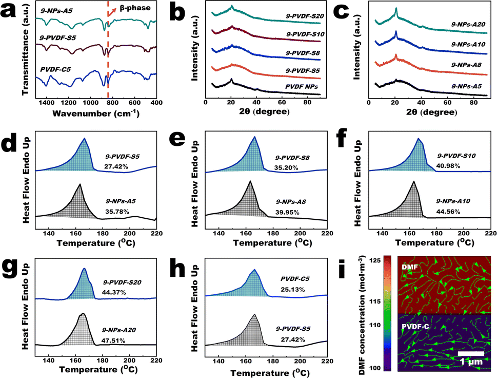 | ||
| Fig. 3 Mechanism of the membrane fabrication procedure. (a) Fourier transform infrared spectra of PVDF-NP aggregates and PVDF-C5, 9-PVDF-S5 and 9-NPs-A5 membranes; (b) X-ray diffraction (XRD) patterns of 9-PVDF-S5, 9-PVDF-S8, 9-PVDF-S10, 9-PVDF-S20 membranes and PVDF-NP aggregates; (c) XRD patterns of 9-NPs-A5, 9-NPs-A8, 9-NPs-A10, and 9-NPs-A20 membranes; (d–g) DSC thermograms of the 9-PVDF-S and 9-NPs-A membranes; (h) DSC thermograms of the 9-PVDF-S5 and PVDF-C5 membranes; (i) simulation of the diffusion of DMF in the PVDF-S membrane. The green arrow line represents the transport path of DMF (COMSOL multiphysics). | ||
The above results suggest that although NPs with uniform sizes and shapes can be formed, whether the NPs can be uniformly distributed on the membrane surface is unknown. The dissolution procedure shown in Fig. 1a and d and Video S4† revealed that under the same vacuum pressure, the rate of DMF permeation when dissolving the NP aggregates was notably lower than those of NP dispersion filtration and water filtration after NIPS. This was caused by the large resistance encountered by DMF during its transportation, implying that a lot of energy was used for the interaction of DMF with PVDF. The COMSOL multiphysics simulations (Fig. 3i and S9†) demonstrated that the chemical-potential gradient of DMF diffusion and pressure propels crystal structures in PVDF-C to move, ultimately leading them to be uniformly distributed within the membrane. In the microphase separation process shown in Fig. 1d and g, the COMSOL multiphysics simulations (Fig. 3i and S9†) also demonstrated that under vacuum pressure, DMF diffuses uniformly in all directions within the PVDF-C, leading to uniformly distributed DMF in the membrane. Therefore, the PVDF concentration in all directions in the membrane should be simultaneously increased to form uniformly distributed crystal seeds (the PVDF-S consists of free PVDF polymer and PVDF crystal seeds, and due to good compatibility between these substances, crystal seeds do not agglomerate, Fig. 1h). In the procedure of NIPS and self-seeding, the polymer solution (PVDF-S) has consistent fluctuation wavelength.27 Therefore, the rich phase (ideal environment for self-seeding) can be equidistantly distributed.27 Since the crystal seeds and the areas for seed growth can be uniformly distributed, uniform nanoparticle arrangement with uniform nanoparticle size inside the NPs-A membrane can be achieved. Consequently, the pore size between the nanoparticles in the membrane should be uniformly distributed (Fig. 1k–l).
Based on the above analysis, we attempt to explain the phenomena presented in Fig. 2. Upon analysis of the XRD and DSC data, we observed that the crystallinity of the PVDF-C and PVDF-S membranes gradually increased as the volume of the PVDF solution increased (Fig. 3b, d–g and S7†). This indicates that the ability of DMF to dissolve PVDF-NP aggregates gradually weakens. This may be due to the fact that during the dissolution process, a significant number of polymer molecules within the crystal cannot be dissolved into free polymer, resulting in an increase in the volume and weight of crystal structures within the PVDF-S membrane. As a result, DMF may not be able to effectively move large-mass crystal structures during filtration, leading to the uneven distribution of crystal seeds within the membrane and consequently resulting in NPs with low levels of uniformity (Fig. 2e–f). To further verify this, instead of filtration, we only dissolved the PVDF-NP aggregates in DMF to prepare a PVDF-PI membrane (Fig. 2h and Table 1) and found that the NPs were not homogeneously distributed, and large pores were formed inside the PVDF-PI membrane. This result proved that a vacuum filtration is needed during DMF dissolution to achieve uniform distributions of nanoparticles in the membrane. Additionally, the appearance of numerous defects in the 9-NPs-A2 membrane (Fig. 2d) may be attributed to the fact that the volume of the PVDF solution was too low to fabricate an intact membrane (inset in Fig. 2d). During the microphase separation stage, increasing the PVDF-C filtration time from 0 to 9 minutes resulted in a gradual improvement in the uniformity of NP distribution (Fig. 1l, l, 2i and j). This may be attributed to the gradual formation and uniform distribution of crystal seeds during this period, which triggers the self-seeding process upon addition of water. However, further extending the filtration time to 14 minutes may lead to the filtration of free polymer through the membrane, resulting in a reduction in the presence of free polymer during the subsequent NIPS process. Therefore, a 14-NPs-A5 membrane was fabricated with a decreased presence of linear polymers (Fig. 2k). Further prolonging the filtration time to 30 minutes verified that most of the free polymers were filtered through the membrane. Cross-section images in Fig. S10† show that the thickness of the 30-NPs-A5 membrane was lower than 10 nm, which was significantly decreased compared to that of the 9-NPs-A5 membrane (Fig. 4a). Moreover, prolonging the filtration time to 30 minutes may result in an excessively high concentration of PVDF within PVDF-S and gradual solidification, leading to the disappearance of both the nanoparticles and linear polymers (Fig. 2l).
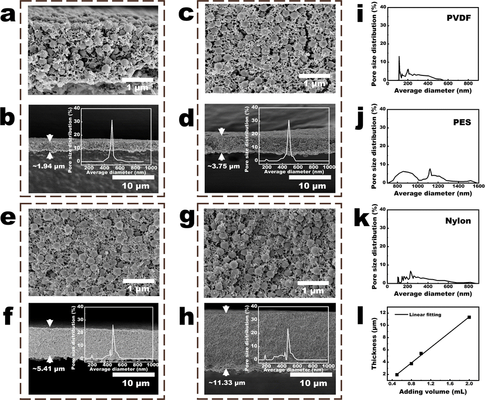 | ||
| Fig. 4 Parameters of the NPs-A membranes. (a and b) Cross-sectional images of the 9-NPs-A5 membrane. Inset in Fig. 3b is the pore-size distribution of the membrane; (c and d) cross-sectional images of the 9-NPs-A8 membrane. Inset in Fig. 3d shows the pore-size distribution of the membrane; (e and f) cross-sectional images of the 9-NPs-A10 membrane. Inset in Fig. 3f shows the pore-size distribution of the membrane; (g and h) cross-sectional images of the 9-NPs-A20 membrane. Inset in Fig. 3h shows the pore-size distribution of the membrane; (i–k) pore size distribution of the commercial (i) PVDF, (j) PES, and (k) nylon membranes; (l) linear relationship between the added volume of the PVDF solution and the membrane thicknesses. | ||
Parameters of the NPs-A membranes
As shown in Fig. 4a–h and S11,† the sizes and distributions of the NPs in the cross-section of the NPs-A membrane were not substantially different from those on the NPs-A membrane surface. On one hand, with an increase in the volume of the PVDF solution (Table 1), the NPs within 9-NPs-A8–20 membranes became increasingly uneven (Fig. 4a, c, e, and g). On the other hand, with an increase in the time of DMF filtration (Table 1), the NPs within 0–9-NPs-A5 membranes became increasingly even (Fig. 4a, S11a and c†). Therefore, with an increase in the uniformities of the distributions of NPs in the membrane, the pore-size distributions of NPs-A membrane tended to concentrate, and the 9-NPs-A5 membrane exhibited the narrowest pore-size distribution (insets in Fig. 4b, d, f, h, S11b and d†). The 9-NPs-A5 membrane, with narrow pore size distribution, was attributed to the development of evenly sized membrane pores between uniformly sized and uniformly distributed NPs.The pore size distributions of the NPs-A membranes were initially compared with those of advanced commercial water treatment membranes, including PVDF, PES, and nylon membranes, which have an average pore size of 0.45 μm, as illustrated in Fig. 4i–k. The results demonstrated that the pore size distributions of the 5–9-NPs-A5 and 9-NPs-A5–20 membranes in this study were narrower than those of the commercial membranes. Subsequently, the pore size distributions of the NPs-A membranes were compared with those of membranes employing block copolymers for the SNIPS strategy, as shown in Fig. S12.† The findings indicated that most membranes have a narrower pore size distribution than the NPS-A5 membranes. This is primarily due to the precise control over membrane pore sizes afforded by the microphase separation of block polymers.11,16,17 However, designing an ideal block copolymer remains a challenge in polymer science. The high cost of preparation, complex chemical bonding reactions, and the impact of composition and structure all contribute to the difficulty. Therefore, the NPs-A membranes, with their simple and practical preparation method, low cost of raw materials, and smaller pore size distribution compared to existing commercial membranes, may present a promising application prospect.
Moreover, with the increase in the volume of the PVDF solution added to water (Table 1), the number of NPs gradually increased (Fig. S2†), which led to a progressive thickening of the formed 9-NPs-AX membrane. Additionally, it was demonstrated that the thickness of the 9-NPs-A membrane was directly proportional to the volume of the PVDF solution added to water (Fig. 4l and Table S1†). Besides, due to the narrowed pore size distribution and the decreased membrane thickness, the membrane porosity also increased with the increase in volume of PVDF solution (Table S1†). Thus, compared to the 9-NPs-A8–20 membranes, the 9-NPs-A5 membrane with the best membrane pore size distributions also demonstrated the lowest thickness and highest porosity (1.94 μm, Fig. 4b, d, f, and h). As for the 0–9-NPs-A5 membranes, the membrane pore size distribution narrowed and the thickness decreased as the DMF filtration time increased. However, the 0-NPs-A5 membrane had the highest porosity among these membranes. The reason for this may be that the PVDF-C did not undergo further DMF filtration, resulting in a higher concentration of DMF in PVDF-C. As a result, a large-pore porous structure is present within the membrane after NIPS, as shown in Fig. S11a.† Consequently, the pore size, thickness, and porosity of the membrane are increased compared to the 5–9-NPs-A5 membranes. Based on the following Hagen–Poiseuille equation:
| J = επrp2ΔP/8ημL | (1) |
Separation performances of the 9-NPs-A membranes
In order to present the influence of the parameters on the membrane performance more clearly, we selected a series of 9-NPs-AX membranes (X represents 0.5, 0.8, 1.0, and 2.0 mL) with gradually changing pore size distributions, membrane thickness, and porosity for comparison. Quantitative tests revealed that the water flux of the 9-NPs-A5 membrane under 0.5 bar was 2924.67 ± 28.02 L m−2 h−1 (Fig. 5a). Based on the findings presented in Table S2† from literature review of PVDF-based membranes with comparable pore sizes, it was observed that the performance of the 9-NPs-A5 membrane was higher than those of most existing PVDF-based membranes with a similar pore size reported in previous studies. Moreover, the water fluxes of 9-NPs-A8, 9-NPs-A10, and 9-NPs-A20 exhibited 14.53, 37.62, and 47.46% deviations from the theoretical value, respectively (5.1 parts in the ESI†). The tortuosity parameter is calculated based on the experimental flux of the 9-NPs-A5 membrane and is then used in combination with the data from Table S1† to calculate the theoretical fluxes for other 9-NPs-A membranes. Since the tortuosity parameter of all 9-NPs-A membranes is assumed to be the same as that of the 9-NPs-A5 membrane in the calculation process, the calculated theoretical fluxes for all membranes are assumed to be the same as the tortuosity of the 9-NPs-A5 membrane. Therefore, by comparing the calculated results with the experimental flux of the membranes, the effect of the pore tortuosity on membrane flux can be intuitively reflected by the deviation between the experimental and theoretical data. This is because the Hagen–Poiseuille equation (eqn (1)) regards the pores in the separation membrane as vertical cylindrical channels and neglects the impact of fluid flow resistance caused by the tortuosities of the pores. Thus, compared to the case of the water flux of the 9-NPs-A5 membrane, the water fluxes of the other more tortuous separation membranes were significantly lower than the theoretical value. Additionally, with an increase in membrane thickness, the tortuosities of the membrane pores increased, thereby causing a decrease in membrane porosity and further deviations of the water fluxes of the thicker 9-NPs-A membrane from the theoretical value (Fig. 5a).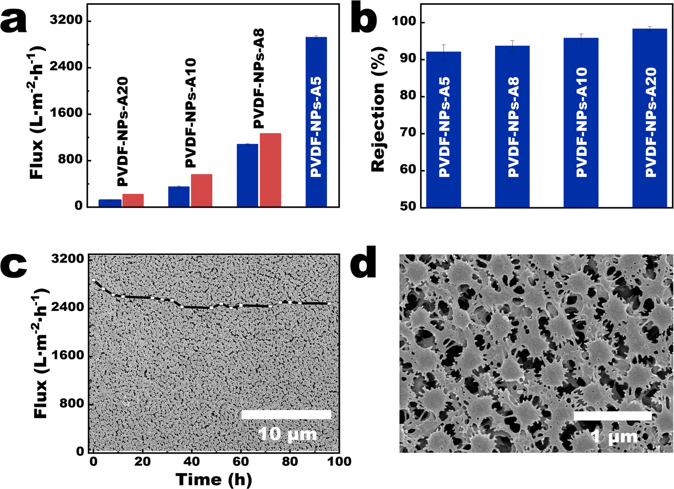 | ||
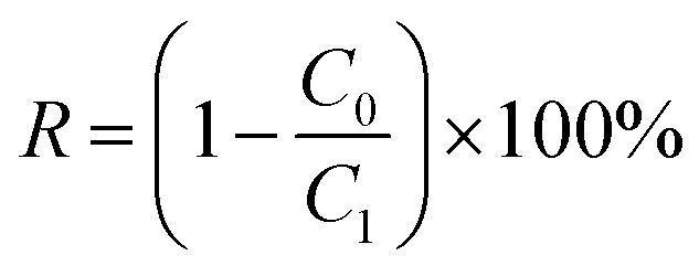
| Fig. 5 Separation performances of the 9-NPs-A membranes. (a) The flux of membranes; (b) the rejection rates of polystyrene microspheres (particle size is 500 nm) for the 9-NPs-A membranes (the blue bars represent the rejection of 9-NPs-A membranes; the red bars represent the theoretical flux of the 9-NPs-A membranes); (c and d) surface morphology of the 9-NPs-A5 membrane. Inset in (c) shows the flux of the 9-NPs-A5 membrane for long-term stability. | ||
As the average pore sizes of 9-NPs-A membranes ranged between 490 and 540 nm (Table S1†) and the pore-size distributions of these membranes were narrow, 9-NPs-A membranes demonstrated effective rejections of microplastics with comparable sizes (5.1 parts in the ESI†). The rejection rates of 500 nm polystyrene (PS) microspheres were higher than 91% (Fig. 5b), and the rejection rates of 700 and 1000 nm PS microspheres reached nearly 100% (Fig. S14†). The 9-NPs-A5 membrane also exhibited excellent long-term stability. The flux of the 9-NPs-A5 membrane remained constant during long-term operation (inset in Fig. 5c), lasting 96 h under 0.5 bar, with no membrane breakdown. Scanning electron microscopy (SEM) images of the 9-NPs-A5 membrane indicated that the NPs on the membrane surface were large (approximately 320 nm, Fig. 5c and d). As shown in Fig. S15,† the average DMT modulus of PVDF nanoparticles is 3.16 GPa, while the average DMT modulus of commercial PVDF membrane is 7.45 GPa. This indicates that PVDF nanoparticles are relatively softer, leading to the deformation of nanoparticles during long-term operation. This deformation results in a reduction in the pore size within the membrane, leading to a decrease in membrane flux (insets in Fig. 5c).
Experimental
Materials
Commercial nylon membranes (solvent-resistant organic microfiltration membranes, average pore size = 0.22 μm) used were obtained from Tianjin Jinteng Experimental Equipment Co., Ltd., China. Commercial nylon membranes (average pore size = 0.45 μm) were obtained from GVS North America Sanford, USA. The commercial PVDF membrane (average pore size = 0.45 μm) was obtained from Cytiya, USA. The commercial PES membrane (average pore size = 0.45 μm) was obtained from Beyotime Biotechnology, China. Polyvinylidene (PVDF, average molecular weight = 0.4 MDa), N,N-dimethylformamide (DMF), ethanol (95 wt%), n-butanol, and formic acid were purchased from Shanghai Macklin Biochemical Co., Ltd., China. Fluorescent labelled polystyrene microspheres (particle size = 500, 700, and 1000 nm) were purchased from Tianjin Baseline ChromTech Research Centre, China.Synthesis of the PVDF nanoparticles (PVDF NPs)
The PVDF NPs were prepared based on our previous work.23 Briefly, 0.6 g of PVDF was fully dissolved in DMF (100 mL) at 60 °C for 12 h to obtain a homogeneous PVDF solution. After the solution had cooled to 25 °C, a certain volume thereof was added to deionized water (200 mL) to obtain a PVDF NP dispersion. During the fabrication procedure, the added volume of the PVDF solution was regulated, as shown in Table 1.Fabrication of the PVDF nanoparticle (PVDF-NP) aggregates
A commercial nylon microfiltration membrane, with an average pore size of 0.22 μm and a diameter of 50 mm, was installed in a vacuum filtration cup. Then, 200 mL of the PVDF NP dispersion was poured into the filtration cup and filtered under a vacuum pressure of 0.95 bar. After the filtration process, the PVDF-NP aggregates were obtained on the membrane surface. The pretreatment method for characterizing the PVDF-NP aggregates involved drying the as-prepared aggregates in an oven at 60 °C for 0.5 hours. The parameters and labelled aggregates are shown in Table 1.Fabrication of the PVDF casting solution (PVDF-C) and the PVDF-C membrane
Building on the previously obtained PVDF-NP aggregates with a commercial nylon microfiltration membrane (substrate), an approach to partially dissolve the PVDF-NP aggregates involved the careful addition of 20 mL of DMF into the filtration cup, followed by vacuum filtration at a pressure of 0.95 bar until the point where a homogeneously dispersed slurry of the PVDF polymer was left on the surface of the microfiltration membrane within the cup. The polymer slurry is denoted as PVDF casting solution (PVDF-C). The pretreatment method for characterizing the PVDF-C involved freeze-drying the as-prepared PVDF-C with a substrate, followed by treatment with formic acid to dissolve the substrate. The freeze-dried PVDF-C was identified as the PVDF-C membrane. The parameters and labeled membranes are detailed in Table 1.Fabrication of the PVDF seed (PVDF-S) and the PVDF-S membrane
Building on the previously obtained PVDF-C with a substrate, the process advanced by continuing the vacuum filtration of PVDF-C at a pressure of 0.95 bar for a specified duration. This step was crucial to ensure that the PVDF crystalline seeds were well dispersed throughout the slurry. The well-dispersed PVDF crystal seeds were denoted as PVDF-S. The pretreatment method for characterizing the PVDF-S involved freeze-drying the as-prepared PVDF-S with a substrate, followed by treatment with formic acid to dissolve the substrate. The freeze-dried PVDF-S were identified as the PVDF-S membrane. The parameters and labeled membranes are detailed in Table 1.Fabrication of the PVDF-NPs array (NPs-A) membrane
Building on the previously obtained PVDF-S with a substrate, 200 mL of water was carefully added into the filtration cup and filtered under a vacuum pressure of 0.95 bar to obtain a NPs-A membrane with a substrate. The as-prepared membrane was thoroughly treated with formic acid to remove the substrate and stored in deionization water for later use. Different NPs-A membranes can be obtained by adjusting the membrane parameters. The parameters and labeled membranes are shown in Table 1.Fabrication of the PVDF phase inversion (PVDF-PI) membrane
Building on the previously obtained PVDF-NP aggregates with a substrate, 20 mL of DMF were carefully added into the filtration cup. Without applying vacuum filtration, the PVDF-NP aggregates were immersed in DMF for 8 hours. Subsequently, DMF was meticulously removed, resulting in the formation of a PVDF casting solution (PVDF-C) on the surface of the microfiltration membrane. Finally, 200 mL of water were carefully added to the filtration cup and subjected to vacuum filtration under a pressure of 0.95 bar. This procedure yielded a PVDF phase inversion (PVDF-PI) membrane with a substrate. The pretreatment method for characterizing the PVDF-PI involved freeze-drying the as-prepared PVDF-PI with a substrate. The parameters and labelled membranes can be seen in Table 1.Characterization
A freeze dryer (freeze dryer FD-8, SIM International Group Co. LTD, USA) was used for the fabrication of PVDF-C and PVDF-S membranes, as well as for the sample treatment prior to characterization via FESEM and STEM. The surface and some cross-sectional morphologies of NPs-A, PVDF-NP aggregates, PVDF-C, PVDF-S, and PVDF-PI membranes were characterized by FESEM (Hitachi, SU8020, Japan). The cross-sectional morphologies were obtained by wetting the membrane with liquid nitrogen and sputtering the samples with gold before analysis. The crystalline phase of the PVDF-NPs, PVDF-C5, NPs-A5 and PVDF-S5 membrane samples was determined by FTIR (iS10) using the KBr pellet and ATR methods, respectively, under the following conditions: wavenumber range = 400–4000 cm−1, resolution = 4 cm−1, signal-to-noise ratio = 50![[thin space (1/6-em)]](https://www.rsc.org/images/entities/char_2009.gif) 000:1, and the number of scans = 64. The size distributions and concentrations of the PVDF NPs were determined using a NP tracking analyzer (NanoSight NS300, NTA). X-ray diffraction (XRD) measurements were carried out on a X'Pert Pro-MPD advanced diffractometer equipped with Cu Kα radiation operated at 50 kV and 40 mA to study the crystallinity of the PVDF NPs, PVDF-C, PVDF-S, and NPs-A membranes. Differential scanning calorimetry (DSC) was performed using a Mettler Toledo DSC 3 apparatus under a nitrogen atmosphere at a heating rate of 10 ± 0.2 °C min−1 to evaluate the crystalline fraction of the NPs-A, PVDF-C, and PVDF-S membranes. The STEM images of the NPs-A and PVDF-S membranes were obtained using an FEI Talos-F200X system (Thermal Scientific Talos™) with an operating voltage of 200 keV. The membrane samples were subjected to pulverization and ultrasonication in ethanol. Following this process, the lacey support films were used to collect the membrane residues in ethanol. During collection, the residues were deposited onto the lacey support films. The samples were then subjected to drying, preparing them for subsequent use. The nanoparticle sample was prepared by immersing the lacey support films in the PVDF-NP dispersions for 5 minutes and then freeze-drying the sample prior to use. The dynamic viscosity of PVDF-C was measured at 35 °C using an Ubbelohde viscometer (Shanghai Longtuo Company, Shanghai, China). The pore size distribution of NPs-A membranes was characterized using a capillary flow porometer (CFP-1500AE, PMI Inc). This study involved collecting 43 pores with varying radii and determining the percentage of the quantity for each pore radius within the membrane, in order to evaluate the distribution of pore radius within the membrane. Membrane porosity was calculated through a dry-wet weight method. At first, the dry weight (W0) of the membrane with an area of 12.57 cm2 was obtained through freeze-drying. Subsequently, the samples were soaked in isopropanol for 24 h. After mopping the surface water with filter paper, the wet weight (W1) was obtained. The membrane porosity was calculated using eqn (2):28
000:1, and the number of scans = 64. The size distributions and concentrations of the PVDF NPs were determined using a NP tracking analyzer (NanoSight NS300, NTA). X-ray diffraction (XRD) measurements were carried out on a X'Pert Pro-MPD advanced diffractometer equipped with Cu Kα radiation operated at 50 kV and 40 mA to study the crystallinity of the PVDF NPs, PVDF-C, PVDF-S, and NPs-A membranes. Differential scanning calorimetry (DSC) was performed using a Mettler Toledo DSC 3 apparatus under a nitrogen atmosphere at a heating rate of 10 ± 0.2 °C min−1 to evaluate the crystalline fraction of the NPs-A, PVDF-C, and PVDF-S membranes. The STEM images of the NPs-A and PVDF-S membranes were obtained using an FEI Talos-F200X system (Thermal Scientific Talos™) with an operating voltage of 200 keV. The membrane samples were subjected to pulverization and ultrasonication in ethanol. Following this process, the lacey support films were used to collect the membrane residues in ethanol. During collection, the residues were deposited onto the lacey support films. The samples were then subjected to drying, preparing them for subsequent use. The nanoparticle sample was prepared by immersing the lacey support films in the PVDF-NP dispersions for 5 minutes and then freeze-drying the sample prior to use. The dynamic viscosity of PVDF-C was measured at 35 °C using an Ubbelohde viscometer (Shanghai Longtuo Company, Shanghai, China). The pore size distribution of NPs-A membranes was characterized using a capillary flow porometer (CFP-1500AE, PMI Inc). This study involved collecting 43 pores with varying radii and determining the percentage of the quantity for each pore radius within the membrane, in order to evaluate the distribution of pore radius within the membrane. Membrane porosity was calculated through a dry-wet weight method. At first, the dry weight (W0) of the membrane with an area of 12.57 cm2 was obtained through freeze-drying. Subsequently, the samples were soaked in isopropanol for 24 h. After mopping the surface water with filter paper, the wet weight (W1) was obtained. The membrane porosity was calculated using eqn (2):28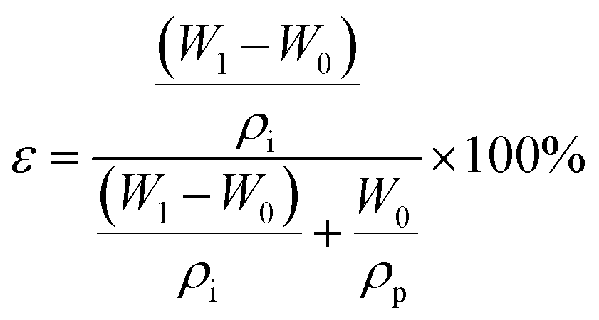 | (2) |
Evaluation of membrane performances
The separation performance of the membranes was evaluated using a filtration cell with a filtration area of 4.1 cm2 (Millipore model 8010). The membrane is attached to non-woven fabric before testing to ensure that the membrane is not damaged or deformed due to pressure during the pressing process caused by the grooves at the bottom of the filtration cell. All membranes were first operated in deionized water at 0.5 bar for 15 min prior to testing to ensure system stability. The permeability in pure water was tested for 10 min at 0.5 bar. Each sample was tested in triplicate, and the average and standard deviation of the three test data were calculated. The pure water flux of the proposed membrane was calculated using eqn (3):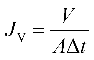 | (3) |
 | (4) |
Membrane stability
The long-term stability of the 9-NPS-A5 membranes was evaluated by monitoring the water flux at 0.5 bar for four consecutive days. Samples were collected every 4 h from 9:00 to 21:00 to measure the membrane flux. Deionized water was replaced after each collection. After the experiment, the membrane was extracted and characterized using SEM to observe the membrane surface morphology.Conclusions
In this study, we try to extend the application of the SNIP strategy to semi-crystalline polymers through the introduction of the self-seeding process. The findings of this study demonstrate that during the dissolution of PVDF nanoparticle aggregates, a majority of the PVDF crystals undergo a transformation into free polymers, while the remaining crystalline structures become evenly dispersed in the casting solution. Further microphase separation leads to the generation of single crystals (crystal seeds) with molecular chains that are orderly arranged. By applying the NIPS process, the evenly distributed rich phase restricts the mobility of free polymers, allowing the crystal seeds to grow and form uniformly distributed nanoparticles with uniform size and shape (known as self-seeding). Characterized by its narrow pore size distribution, the obtained membrane shows improved flux and rejection towards pore-size-similar microplastics.Author contributions
Y. M. and X. Z conceived the idea and designed the experiments. Y. M. and B. H. performed the fabrication and characterization of the membranes. Y. M. and B. H. carried out the performance evaluation experiments of the membranes. B. H. and X. Z. supervised the project. Y. M. wrote the manuscript.Conflicts of interest
There are no conflicts to declare.Acknowledgements
This study was supported by the China National Science Fund for Distinguished Young Scholars (No. 41925031), the National Natural Science Foundation of China (No. 42177065, 41930865, and 42321005), and the National Key Research and Development Project (2023YFC3200167). Financial support from the China Postdoctoral Science Foundation (2021M700889), the Guangdong Foundation for Program of Science and Technology Research (2023B1212060044, 2019QN01L682 and 2019B121201004), Guangdong Basic and Applied Basic Research Foundation (2023B1515040007), and the GDAS Special Project of Science and Technology Development (2020GDASYL-20200102013, 2020GDASYL-20200101002, and 2022GDASZH-2022010105) is also acknowledged.Notes and references
- D. S. Sholl and R. P. Lively, Nature, 2016, 532, 435–437 CrossRef PubMed.
- G. Belfort, Angew. Chem., Int. Ed., 2019, 58, 1892–1902 CrossRef CAS PubMed.
- M. Muller and V. Abetz, Chem. Rev., 2021, 121, 14189–14231 CrossRef PubMed.
- Y. Tang, Y. Lin, D. M. Ford, X. Qian, M. R. Cervellere, P. C. Millett and X. Wang, J. Membr. Sci., 2021, 640, 119810 CrossRef CAS.
- H. B. Park, J. Kamcev, L. M. Robeson, M. Elimelech and B. D. Freeman, Science, 2017, 356(6343), 1–10 CrossRef PubMed.
- Z. Zhang, A. Simon, C. Abetz, M. Held, A.-L. Hohme, E. S. Schneider, T. Segal-Peretz and V. Abetz, Adv. Mater., 2021, 33(48), 2105251 CrossRef CAS PubMed.
- Z. Zhang, C. Chen, S. S. Zhang, X. Y. Ye, J. M. Zhou and Y. Wang, J. Membr. Sci., 2022, 662, 121021 CrossRef CAS.
- S. Dutt, P. Apel, N. Lizunov, C. Notthoff, Q. Wen, C. Trautmann, P. Mota-Santiago, N. Kirby and P. Kluth, J. Membr. Sci., 2021, 638, 119681 CrossRef CAS.
- L. M. Guo, K. Ntetsikas, G. Zapsas, R. Thankamony, Z. P. Lai and N. Hadjichristidis, Angew. Chem., Int. Ed., 2023, 135(4), e202212400 CrossRef.
- H. Masuda and K. Fukuda, Science, 1995, 268, 1466–1468 CrossRef CAS PubMed.
- C.-Y. Yang, G.-D. Zhu, Z. Yi, Y. Zhou and C.-J. Gao, Chem. Eng. J., 2021, 424, 128912 CrossRef CAS.
- K. Y. Liang, X. Li, L. Wang, Z. Y. Xie, Q. M. Wang, K. Wang, J. P. Wu, H. Z. Yu and X. Y. Qiu, J. Membr. Sci., 2023, 669, 121277 CrossRef CAS.
- Z. Shu, H. Z. Li, Y. Shi, D. Y. Zuo, Z. Yi and C. J. Gao, J. Membr. Sci., 2023, 672, 121450 CrossRef CAS.
- G. D. Zhu, Y. R. Yin, Z. N. Li, Y. Y. Qiu, Z. Yi and C. J. Gao, J. Membr. Sci., 2019, 582, 391–401 CrossRef CAS.
- M. Radjabian and V. Abetz, Adv. Mater., 2015, 27, 352–355 CrossRef CAS PubMed.
- N. Hampu, J. R. Werber, W. Y. Chan, E. C. Feinberg and M. A. Hillmyer, ACS Nano, 2020, 14, 16446–16471 CrossRef CAS PubMed.
- K. V. Peinemann, V. Abetz and P. F. W. Simon, Nat. Mater., 2007, 6, 992–996 CrossRef CAS PubMed.
- L. Gao, S. Mei, Q. Qian, S. Yu, B. Zhao, Y. Tu and C. Y. Li, Angew. Chem., Int. Ed., 2023, 62(15), e202217267 CrossRef CAS PubMed.
- J. Xu, Y. Ma, W. Hu, M. Rehahn and G. Reiter, Nat. Mater., 2009, 8, 348–353 CrossRef CAS PubMed.
- G. Reiter, Chem. Soc. Rev., 2014, 43, 2055–2065 RSC.
- D. J. Blundell and A. Keller, J. Macromol. Sci., Part B: Phys., 1968, 2, 301–336 CrossRef CAS.
- S. P. Nunes, A. R. Behzad, B. Hooghan, R. Sougrat, M. Karunakaran, N. Pradeep, U. Vainio and K. V. Peinemann, ACS Nano, 2011, 5, 3516–3522 CrossRef CAS PubMed.
- Y. Ma, X. Zhao, Y. Shen, Y. Wang and B. He, Desalination, 2023, 546, 116230 CrossRef CAS.
- H. Iijima, A. Kataoka and K. Kamide, Polym. J., 1995, 27, 1033–1043 CrossRef CAS.
- P. Martins, A. C. Lopes and S. Lanceros-Mendez, Prog. Polym. Sci., 2014, 39, 683–706 CrossRef CAS.
- P. L. Hanks and D. R. Lloyd, J. Membr. Sci., 2007, 306, 125–133 CrossRef CAS.
- J. W. Cahn, J. Chem. Phys., 1965, 42, 93 CrossRef CAS.
- W. He, S. Fan, G. Liu, L. Zhou, L. Chai, H. Zhu, C. Li and B. Yu, Sep. Purif. Technol., 2023, 306, 122446 CrossRef CAS.
- X. Zhang, H.-N. Li, C.-Y. Zhu, X.-J. Huang, A. Greiner and Z.-K. Xu, Chem. Eng. J., 2022, 434, 134758 CrossRef CAS.
Footnote |
| † Electronic supplementary information (ESI) available. See DOI: https://doi.org/10.1039/d3na01157g |
| This journal is © The Royal Society of Chemistry 2024 |