DOI:
10.1039/D3NA00785E
(Paper)
Nanoscale Adv., 2024,
6, 578-589
Nickel and nickel oxide nanoparticle-embedded functional carbon nanofibers for lithium sulfur batteries†
Received
16th September 2023
, Accepted 5th December 2023
First published on 6th December 2023
Abstract
Lithium–sulfur (Li–S) batteries are attracting tremendous attention owing to their critical advantages, such as high theoretical capacity of sulfur, cost-effectiveness, and environment-friendliness. Nevertheless, the vast commercialisation of Li–S batteries is severely hindered by sharp capacity decay upon operation and shortened cycle life because of the insulating nature of sulfur along with the solubility of intermediate redox products, lithium polysulfides (LiPSs), in electrolytes. This work proposes the use of multifunctional Ni/NiO-embedded carbon nanofibers (Ni/NiO@CNFs) synthesized by an electrospinning technique with the corresponding heat treatment as promising free-standing current collectors to enhance the kinetics of LiPS redox reactions and to provide prolonged cyclability by utilizing more efficient active materials. The electrochemical performance of the Li–S batteries with Ni/NiO@CNFs with ∼2.0 mg cm−2 sulfur loading at 0.5 and 1.0C current densities delivered initial specific capacities of 1335.1 mA h g−1 and 1190.4 mA h g−1, retrieving high-capacity retention of 77% and 70% after 100 and 200 cycles, respectively. The outcomes of this work disclose the beneficial auxiliary effect of metal and metal oxide nanoparticle embedment onto carbon nanofiber mats as being attractively suited up to achieve high-performance Li–S batteries.
1. Introduction
The application of lithium-ion batteries (LIBs) allowed for the development of new portable devices and electric transportation. Generally, LIBs use cathodes based on intercalation-type transition metal oxides and phosphates.1 However, these compounds provide a limited energy density of LIBs of <400 W h kg−1, which is not enough for high energy storage and power systems, such as renewable energy storage, electric cars, and advanced portable electronics.2 The high cost of these materials, accompanied by safety issues, requires new alternatives, which are safe, non-toxic, and cost-effective. In this regard, lithium–sulfur (Li–S) batteries attracted remarkable attention due to the attractive properties of sulfur, such as a high theoretical energy density of 2600 W h kg−1, a high theoretical capacity of 1675 mA h g−1, low cost, high abundance, and less harmful impact on the environment.3 Nevertheless, the employment of Li–S is considerably slowed down because of the insulating nature of sulfur (5 × 10⁻³⁰ S cm−1 at 25 °C), complicated redox reactions, and high volumetric expansion of the sulfur cathode after reduction to Li2S2/Li2S. Furthermore, soluble electrochemical reaction intermediate product (lithium polysulfides, LiPSs) dissolution occurs, resulting in the degradation of the material and shortening of the battery life. The formation of LiPSs is one of the significant issues of Li–S batteries. These long-chain polysulfides, soluble in electrolytes, cause the so-called “shuttle effect”, prevent efficient ion exchange, sharply reduce the active material's content and, thus, deteriorate the cell performance.4
Currently, one of the most common approaches for suppressing the “shuttle effect” is based on applying carbon materials as a component of the cathode current collector. These materials possess attractive properties, such as a large surface area and variation in pore size distribution for better and steady utilization of sulfur species alongside controlling and buffering the volume expansion upon cycling. Moreover, the high electronic conductivity of carbon provides more efficient electron pathways by lowering its charge transfer resistance.5,6 These porous carbon materials include amorphous carbons, carbon nanotubes (CNTs), carbon nanofibers (CNFs), graphene oxides (GOs), and graphenes.6 Among them, the application of CNFs is an effective approach to address the sulfur volume expansion controlling via its high specific area structure with abundance of adsorption sites. More precisely, recent studies have widely presented the use of CNF-based mats in Li–S cells as a promising way for LiPS retention and their conversion into final products.7–9 However, weak van der Waals forces between nonpolar carbon and polar LiPSs unable to efficiently limit migration of LiPS, thus leading to complicated kinetics of intermediate LiPS conversion into final redox products of the reactions. Therefore, it was suggested to incorporate polar metal nanoparticles (M NPs) and compounds (MnXy) into carbon matrixes to enhance the kinetics of redox reactions and improve the chemisorption of LiPSs, respectively.9,10 Correspondingly, the use of CNFs decorated with metal compounds for LiPS adsorption for improving the Li–S battery performance afterward was presented in several works. Among them, compounds such as vanadium nitride (VN),11 titanium dioxide (TiO2),12 and cobalt phosphide (CoP)13 provided promoted chemical affinity of LiPSs and efficient utilization of the active material. Furthermore, increased interaction of LiPSs with carbon and metal compounds led to improved conductivity, buffering volumetric changes of sulfur and enhanced kinetics of redox reactions in Li–S cells afterwards.14,15
Nickel-based composites had also attracted attention in energy storage systems. For example, Ni and nickel oxide (NiO) nanoparticles were widely investigated as a component in carbon hosts for sulfur. The usage of Ni was justified by its remarkable catalytic effect comparable to that of noble metals such as platinum (Pt) and palladium (Pd), but it is markedly cost-effective. Additionally, it has less harmful impact on the environment than other transition metals such as cobalt (Co) and molybdenum (Mo), and shows a better chemical affinity towards polysulfides.16,17 A comparative study of the catalytic features of Fe-, Co-, and Ni-supported separator modifications performed by M. Chen et al., demonstrated the superior impact of Ni to Fe and Co on the kinetics improvement of LiPS redox reactions leading to more stabilized electrochemical performance of Li–S cells.15 Meanwhile, NiO is a representative of typical adsorbents. It is recognized for its remarkable physicochemical properties such as high chemical stability, adjustable particle size and shape, and excess of active sites.18,19 A pioneer study on the sulfur cathode supported by NiO indicated several advantages over the conventional sulfur cathodes without additives.19 Furthermore, a comparative study of the influence of metal oxides on affinity towards polar LiPSs and the overall reaction kinetics improvement indicated the superior impact of NiO.17
Thus, in this work, the catalytic features of Ni NPs and the chemisorption nature of NiO NPs were employed as synergetic auxiliary additives to CNFs in improving active material utilization and enhancing redox kinetics with LiPSs during cycling and positively affecting the performance of Li–S batteries. It was shown that carbon nanofiber decoration with Ni and NiO NPs (Ni/NiO@CNF) improved the chemical adsorption of lithium polysulfides and enhanced their redox kinetics compared with the bare CNF. Moreover, upon charge–discharge cycling, the cells with these additives delivered initial specific capacities of 1335.1 and 1190.4 mA h g−1 at 0.5 and 1.0C, retrieving 77% and 70% of capacity retention after 100 and 200 cycles, respectively.
2. Methodology
2.1 Fabrication of carbon nanofiber composites
The CNF and Ni/NiO@CNF mats were synthesized by an electrospinning method and used as freestanding current collectors for Li–S batteries. To begin with, a PAN solution in dimethylformamide (DMF, organic solvent) with a concentration of 12 wt% was used in accordance with the literature data reporting the most optimal PAN concentration.20 Particularly, 2.4 g of PAN was dissolved in 20 mL of DMF at room temperature with continuous vigorous stirring for 10 hours to obtain a viscous and transparent solution of PAN. The solution was then injected into a syringe with a tip. The drum inside the electrospinning equipment (Inovenso Ne300, Turkey) was covered with an aluminium collector, which afterward received generated PAN nanofibers from the syringe under the electric field. The set parameters of the procedure under ambient conditions are as follows: applied voltage: 20 kV; flow rate: 2 mL h−1; distance between the nozzle and the collector: 17 cm; rotation speed: 250 rpm; the coating time: 8 hours. The electrospinning of PAN nanofibers was followed by heat treatment in a tubular furnace (STF 1200, Across International, USA) at 280 °C for 2 hours at a heating rate of 5 °C min−1 to provide the nanofibers with oxygen bridges that helped bind the polymeric and metal compound structures and, additionally, to stabilize nanofibers, overall. After that, the nanofibers were detached from the aluminium foil and carbonized at 700 °C for 2 hours at a heating rate of 2 °C min−1 in an argon atmosphere, finally forming CNFs. In the synthesis of Ni/NiO@CNFs, anhydrous Ni(Ac)2 was initially dissolved in DMF in a mass ratio of 1![[thin space (1/6-em)]](https://www.rsc.org/images/entities/char_2009.gif) :2 to PAN, according to the overall balance between polymers and Ni(Ac)2 reported previously.25 Then, the same amount of PAN, as in the case of CNFs, was added to the solution. The subsequent stages of the electrospinning and heat treatment conditions were the same as with the CNF.
:2 to PAN, according to the overall balance between polymers and Ni(Ac)2 reported previously.25 Then, the same amount of PAN, as in the case of CNFs, was added to the solution. The subsequent stages of the electrospinning and heat treatment conditions were the same as with the CNF.
2.2 Material characterization
The nanostructure and morphology of the synthesized carbon nanofiber mats were analysed by scanning electron microscopy (Zeiss Crossbeam 540) and transmission electron microscopy (TEM, JEM-ARM200F “NeoARM”, JEOL, Japan). The crystal structure was studied using X-ray diffraction (Rigaku Smartlab) patterns acquired in the range of 10° to 90° 2θ with Cu Kα radiation (λ = 1.54056 Å). Raman spectra were recorded using a spectrometer (Horiba LabRam Evolution). The measurements of specific surface area and pore volumes were conducted by N2 adsorption and desorption isotherms (Nitrogen porosimeter, Quantachrome Instruments), while the pore size distribution was determined by the Barrett–Joyner–Halenda (BJH) method. The content of Ni/NiO NPs in the Ni/NiO@CNF composite was analysed by trivial thermogravimetric analysis using a Carbolite ELF 1100 °C muffle furnace. The valence change measurements and interaction between lithium polysulfides and interlayers were performed by X-ray photoelectron spectroscopy (NEXSA, Thermo Scientific).
2.3 Lithium polysulfide adsorption analysis
Lithium polysulfide adsorption was carried out via the permeability test by placing CNFs and Ni/NiO@CNFs in a 0.002 M Li2S6 solution for 24 hours and comparing the extent of solution colour change. Then, the extent of light absorption was checked by ultraviolet-visible analysis from the retrieved solutions. Additionally, the chemical binding status with LiPSs was determined by XPS analysis of the S 2p and Ni 2p spectra of CNF and Ni/NiO@CNF mats soaked in a 0.5 M Li2S6 solution for 24 hours and dried in a vacuum oven in advance.
2.4 Electrochemical performance
The electrochemical performance tests were carried out by employing a CR2032 coin cell with a Li metal chip (d = 16 mm) as the reference and counter electrode, a 1.0 M Li2S6 catholyte solution as the source of sulfur species and a commercial Celgard 2400 semi-permeable membrane as the separator. The executed electrolyte was 1 M LiTFSI in 1,3-dioxolane (DOL)/1,2-dimethoxyethane (DME) (v/v, 1:1) with 2 wt% of LiNO3. The 1.0 M Li2S6 catholyte solution was prepared by mixing lithium sulfide with sulfur (molar ratio = 1:5) and stirring in the DOL/DME solution at 60 °C for 24 hours. The areal mass loading of sulfur was estimated using the following equation: ms = Ms/A = (V × M × n × Mr)/A, where ms stands for the sulfur loading (mg cm−2), Ms the sulfur mass for each CNF mat (mg), A the CNF mat's area (cm2), V the catholyte volume (L), M the Li2S6 mole concentration (mol L−1), n the quantity of sulfur in Li2S6 (n = 6 for Li2S6), and Mr the sulfur's relative molecular mass (32 g mol−1).21 In this work, the sulfur loading was ms = 2 mg cm2 with 21 μL of the catholyte volume, respectively. CNF and Ni/NiO@CNF mats were cut into round-shaped disks (d = 16 mm), as well as Celgard 2400 separators (d = 19 mm). Li–S CR2032 type coin cells were assembled in an MBRAUN glovebox (moisture and oxygen level below 0.1 ppm) filled with argon. The procedure of the battery assembling is as follows: first, a carbon nanofiber mat was placed inside the positive cap of the coin case, and 21 μL of the catholyte solution and 15 μL of the electrolyte were added dropwise. Next, the carbon nanofiber mat was covered with a Celgard 2400 separator. After that, another 25 μL of the electrolyte was added, followed by placing the lithium chip (d = 16 mm). Finally, the cells were pressed and sealed in a crimping machine. Several electrochemical analyses were performed regarding the effect of the CNF and Ni/NiO@CNF utilizing the kinetics of polysulfide retention and reversibility of Li–S cells. The current development and determination of sulfur transition redox peak formation in an electrochemical cell were measured by cyclic voltammetry (CV) in the potential range from 1.6 V to 2.8 V at a scan speed of 0.1 mV s−1 and at several scan rates from 0.5 to 0.1 mV s−1 on the electrochemical workstation (Biologic). Meanwhile, the resistance of electrons was analysed by potential electrochemical impedance spectroscopy (PEIS) in the frequency range from 100 kHz to 1 MHz on Biologic as well. The cyclability of assembled cells was investigated by the galvanostatic charge–discharge procedure using a NewAre system at 0.5 and 1.0C rates.
2.5 Symmetric cell analysis
The accelerated electrostatic conversion of LiPSs on the electrode matrix was analysed via assembling symmetric cells and utilizing CV technique at a scan rate of 5 mV s−1. Briefly, symmetric cells consisted of two identical electrodes represented as CNF or Ni/NiO@CNF moisturized with 50 μL of 0.05 M Li2S6 solution and separated by the commercial Celgard 2400 membrane.
2.6 Nucleation test analysis
Coin cells for the nucleation test included synthesized carbon nanofiber mats on the cathode side with the addition of 25 μL of 0.05 M Li2S6 catholyte and being coated with Celgard 2400. The anodic side was composed of 25 μL of 0.5 M LiTFSI electrolyte and a Li metal chip.
2.7
In situ Raman analysis measurements
In situ Raman measurements of LiPS redox kinetics with the CNF and Ni/NiO@CNF were retrieved during discharge–charge cycling of a CR2032 Li–S cell with a hole on the cathode side and sealed with a glass piece. The cell was initially charged up to 2.8 V, which then underwent the whole cycle with every minute spectrum recorded using a Horiba LabRam Evolution spectrophotometer with a 532 nm laser and a ×10.0k magnification microscope objective under standard conditions.
3. Results and discussion
3.1 CNF and Ni/NiO@CNF characterization
CNFs and Ni/NiO@CNFs were successfully synthesized and further their physicochemical and electrochemical characteristics were analysed. Fig. 1a shows the XRD patterns of the prepared carbon nanofibers and composites with Ni and NiO NPs deposited on their surface. Both the XRD patterns of CNFs and Ni/NiO@CNFs had two broad peaks of carbon at 2θ = 24° and 45° corresponding to the crystallized carbon phase of a part of amorphous carbon with the main contribution to the conductivity.22 The XRD patterns of Ni/NiO@CNFs present several reflections at 2θ = 44°, 51°, and 76° that can be indexed to the (111), (200), and (220) planes of Ni NPs alongside 2θ = 37°, 44°, and 63° reflections corresponding to the (111), (200), and (220) planes of NiO NPs. Additionally, these patterns demonstrated the successful recrystallization of Ni/NiO NPs on the surface of the CNF with high purity. The Raman spectra showed the typical amorphous and graphitized carbon peaks in the shift range of 1100–1800 cm−1 (Fig. 1b). Two prominent peaks corresponded to the D-band at 1345 cm−1 and the G-band at 1582 cm−1. The ratio of D- and G-Raman peak intensities characterizes whether the amorphous carbon has ordered or defected structure, resulting in possible shifts of grain boundaries and vacancies and the structure itself.27,28 The D-band intensity was higher than the G-band intensity in both materials pointing at the more disordered structure of carbon nanofibers. The pore characteristics were analysed using a nitrogen porosimeter with Barrett–Joyner–Halenda (BJH) calculations of pore size distribution across the whole surface of materials, while the adsorption–desorption isotherms indicated a quantity of adsorbed nitrogen by pores. The BJH graph demonstrated that most nitrogen adsorption took place in the pores with an average diameter of ∼3.841 nm for Ni/NiO@CNFs, while the average diameter of CNF pores was ∼3.793 nm (Fig. 1c). Besides, microscale pores (d < 5 nm) predominated in the materials, thus, having more active sites for polysulfide entrapping and retention. The adsorption–desorption isotherms showed a higher amount of adsorbed gas by the CNF, indicating that the CNF had a larger specific surface area than that of the Ni/NiO@CNF (Fig. 1d). In addition to that, a simple TGA analysis estimated ∼11% of Ni/NiO NP mass content in the Ni/NiO@CNF composite.
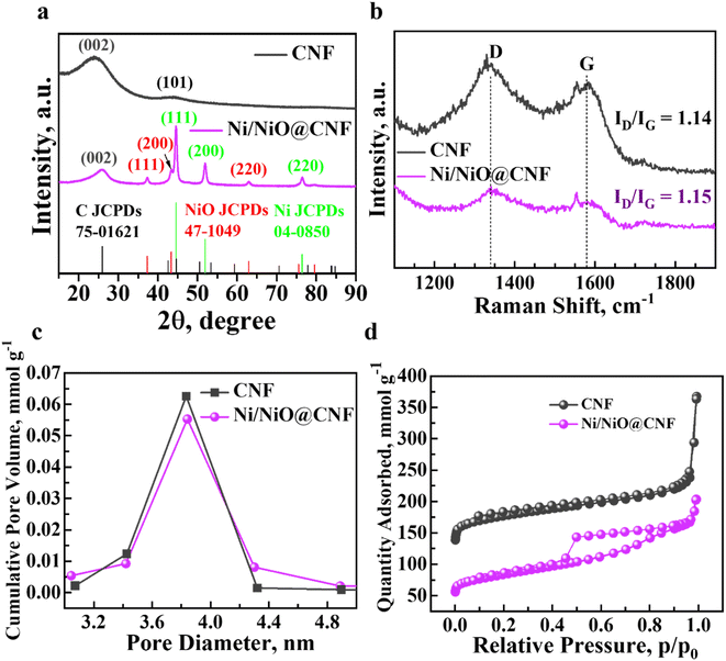 |
| | Fig. 1 Characteristic analysis of the Ni/NiO@CNF and CNF: (a) X-ray diffraction patterns; (b) Raman spectrum; (c) adsorption–desorption isotherms; and (d) BJH pore-distribution analysis. | |
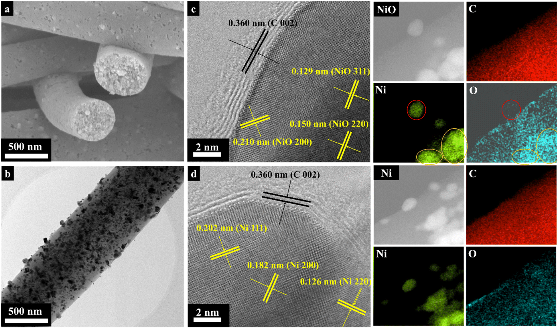
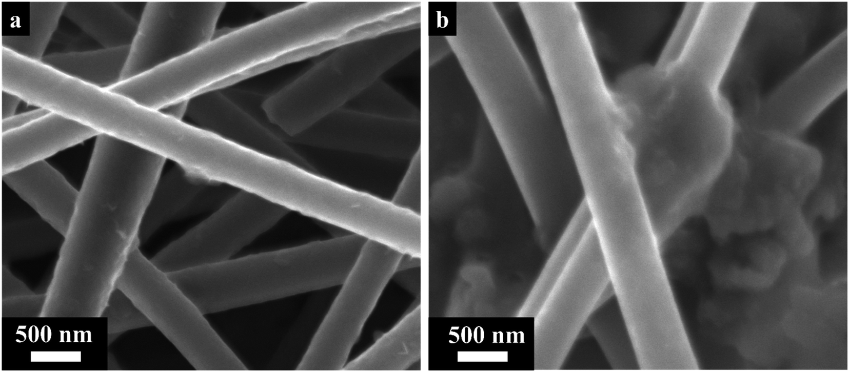
Fig. 2 presents the surface morphology data by scanning electron microscopy, transmission electron microscopy and energy-dispersive X-ray spectroscopy (EDS). Overall, carbon nanofibers were presented as evenly round-shaped long threads with smooth surfaces and diameters of about 460 nm (Fig. S1a†). Fig. 2a demonstrates the uniform recrystallization of Ni/NiO NPs with sizes of 20–30 nm on the surface and inside the nanofibers. The implementation of Ni/NiO NPs did not have a significant impact on the CNF diameter and surface morphology, in general. High-resolution TEM images indicated the formation of non-hollow structures of carbon nanofibers (Fig. S1b†). Moreover, anchoring the recrystallization of Ni/NiO NPs in the carbon nanofibers demonstrated their uniform and steady distribution throughout the composite (Fig. 2b). Meanwhile, more precise bright-field images (BF-TEM) of nanoparticles were obtained, among which Ni/NiO NPs were identified separately, not as a joined composite and encapsulated in nitrogen-doped graphene layers (C 002). According to BF-TEM, the presence of NiO nanoparticles with a diameter of ∼20 nm was justified by identifying labelled lattice distances of 0.210 nm (200), 0.150 nm (220), and 0.129 nm (311) (Fig. 2c). The BF image of the Ni nanoparticle also showed its encapsulation in nitrogen-doped graphene layers. The named lattice distances of 0.202 nm, 0.182 nm, and 0.126 nm correspond to the (111), (200), and (220) planes of Ni NPs, respectively (Fig. 2d). The EDS mapping demonstrated a uniform elemental distribution in the Ni/NiO@CNF, especially, of oxygen that was necessary for forming bridges between non-polar carbon and polar Ni/NiO NPs (Fig. 2c and d).
 |
| | Fig. 2 Morphological analysis of Ni/NiO@CNFs: (a) scanning electron microscopy characterization; (b) high-resolution transmission electron microscopic image; (c) bright-field image of a NiO nanoparticle with its corresponding EDS mapping (red-circled nanoparticle corresponds to the BF image); and (d) bright-field image of a Ni nanoparticle with the corresponding EDS mapping. | |
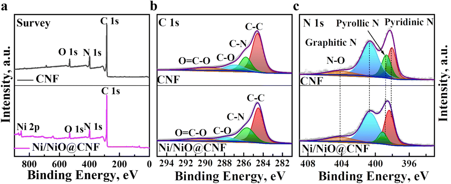
The surface chemistry and elemental binding status of CNF and Ni/NiO@CNF structures were investigated by XPS. Fig. 3a demonstrates the overall survey of carbon nanofiber mats, confirming the presence of C, O, N, and Ni (for Ni/NiO@CNF) elements. The C 1s spectra were interpreted as a signal deconvoluted into four sub-peaks of C–C (284.48 eV), C–N (285.78 eV), C–O (286.88 eV), and O![[double bond, length as m-dash]](https://www.rsc.org/images/entities/char_e001.gif) C–O (289.98 eV) (Fig. 3b). The C–C bond obtained the highest intensity, while the presence of nitrogen (from PAN) was confirmed by the formation of C–N bonds, and OC–O might have arisen from the surface oxidation of the composites. The N 1s spectra deconvoluted into pyridinic N (398.38 eV), graphitic N (400.68 eV), pyrrolic N (398.78 eV) and oxidized state of nitrogen (N–O; 404.28 eV) (Fig. 3c). The formation of each nitrogen peak improves the electronic conductivity along with acting as a Lewis base impactfully contributing to the carbon matrix's adsorption ability towards polar LiPSs. The O 1s spectra of CNF was deconvoluted into C–O–C (532.88 eV) and dominant CO (531.58 eV) peaks, though the same peaks were downshifted in Ni/NiO@CNFs, possibly due to the presence of Ni/NiO nanoparticles contributing to the CO peak as an addition of Ni–O (530.98 eV) (Fig. S2†).
C–O (289.98 eV) (Fig. 3b). The C–C bond obtained the highest intensity, while the presence of nitrogen (from PAN) was confirmed by the formation of C–N bonds, and OC–O might have arisen from the surface oxidation of the composites. The N 1s spectra deconvoluted into pyridinic N (398.38 eV), graphitic N (400.68 eV), pyrrolic N (398.78 eV) and oxidized state of nitrogen (N–O; 404.28 eV) (Fig. 3c). The formation of each nitrogen peak improves the electronic conductivity along with acting as a Lewis base impactfully contributing to the carbon matrix's adsorption ability towards polar LiPSs. The O 1s spectra of CNF was deconvoluted into C–O–C (532.88 eV) and dominant CO (531.58 eV) peaks, though the same peaks were downshifted in Ni/NiO@CNFs, possibly due to the presence of Ni/NiO nanoparticles contributing to the CO peak as an addition of Ni–O (530.98 eV) (Fig. S2†).
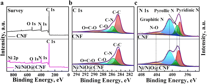 |
| | Fig. 3 High-resolution XPS characterization of the synthesized CNF and Ni/NiO@CNF mats at the pristine state: (a) elemental survey spectra; (b) C 1s spectra; and (c) N 1s spectra. | |
3.2 Interaction with lithium polysulfides
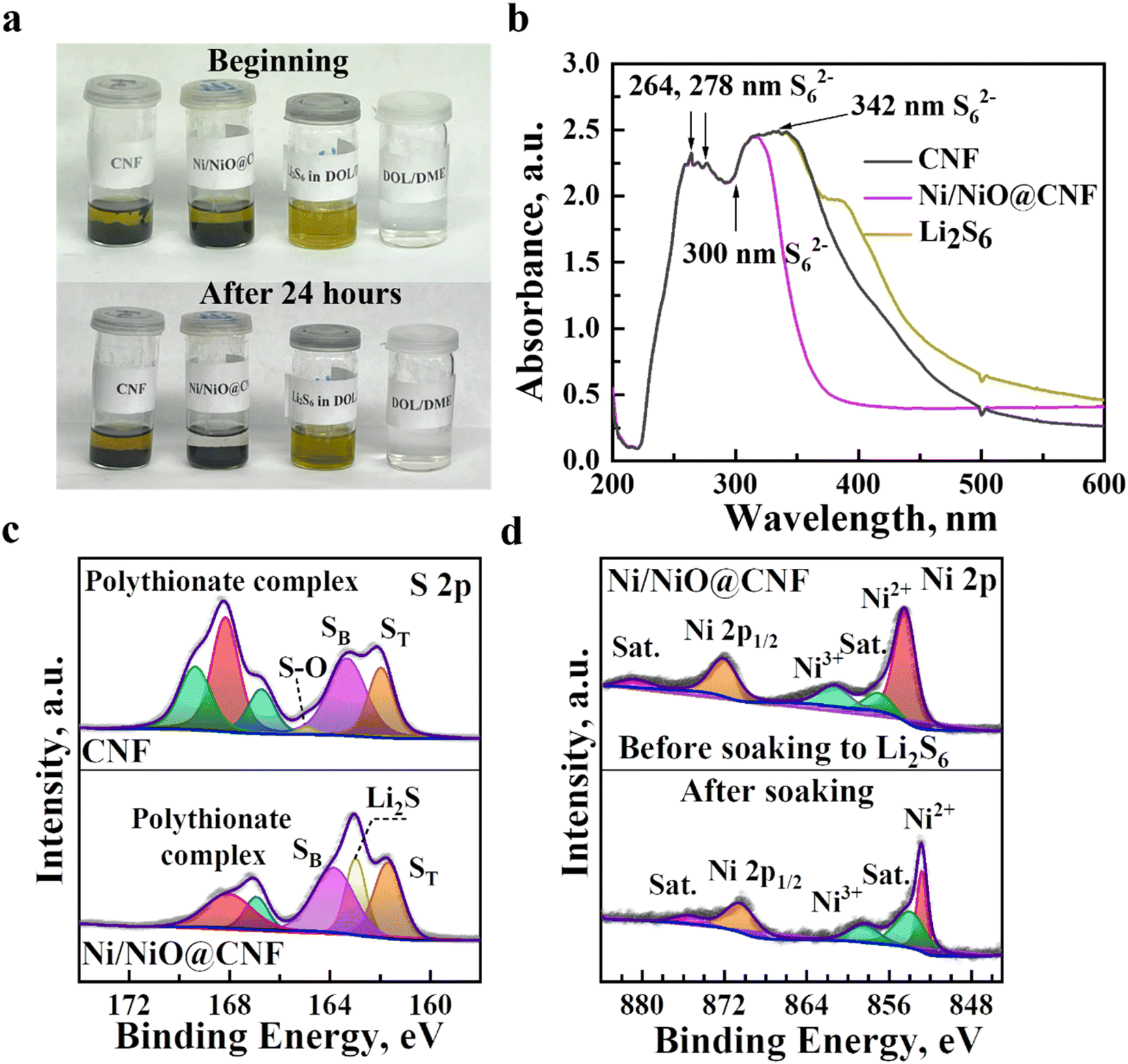
Adsorption tests of Li2S6 were carried out by adding CNFs and Ni/NiO@CNFs into the 0.002 M solution of Li2S6 in DOL/DME (v/v, 1:1) and allowing to rest for 24 hours. The Li2S6 solution with Ni/NiO@CNFs soaking became transparent, while the solution with CNFs remained light yellow in color, suggesting that the chemical interaction of Ni/NiO@CNFs with polysulfides was stronger caused by the use of Ni/NiO NPs (Fig. 4a). Ultraviolet-visible (UV-vis) spectroscopy analysis was performed to estimate the adsorption extent of polysulfides. According to the findings, adsorption peaks at 264, 278, 300 and 342 nm corresponded to polysulfide ions of S62− (Fig. 4b), among which the Ni/NiO@CNF showed less light absorbance, indicating that LiPS adsorption was greater in contrast to the CNF. Further adsorptive behaviour of the synthesised composites towards LiPSs was analysed by soaking the materials in the 0.5 M solution of Li2S6 for 24 hours. Then, the samples were recollected, and the investigation of interaction with sulfur species was maintained by XPS. Fig. 4c shows the S 2p XPS spectra of the CNF and Ni/NiO@CNF treated with lithium polysulfides. The S 2p spectra of the CNF and Ni/NiO@CNF have several major contribution peaks ranging from 158 eV to 174 eV, corresponding to the formation of polythionate complexes (168.18 eV), electron-enriched sulfur species of SB (sulfur bridged, 163.38 eV), ST (sulfur terminated, 161.58 eV), and Li2S (162.98 eV, only risen for the Ni/NiO@CNF). Subsequent analysis of chemical interactions between LiPSs and the synthesized materials was determined in the Ni 2p spectra of the Ni/NiO@CNF before and after adsorption of LiPSs (Fig. 4d). Generally, the Ni 2p spectra of the Ni/NiO@CNF at pristine state are presented as Ni 2p3/2 at 854.48 eV and Ni 2p1/2 at 872.08 eV regions with their subsequent satellite peaks. However, these regions were downshifted by ∼2 eV of binding energies after soaking in lithium polysulfides, indicating the electron transfer from surface-exposed atomic nickel to electron-rich atomic sulfur in Li2S6. The higher the binding energy shift, the higher the interaction between polysulfides and the material.23
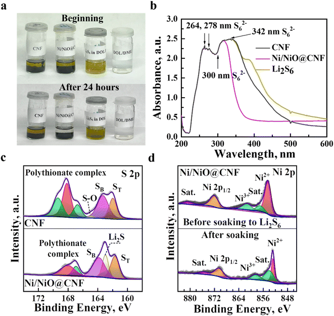 |
| | Fig. 4 Interaction analysis of the Ni/NiO@CNF and CNF with lithium polysulfides: (a) 0.002 M Li2S6 absorption test and (b) UV-Vis spectroscopy test after 24 hours of soaking of the materials in a Li2S6 solution. High-resolution XPS spectra: (c) S 2p core spectra of Li2S6-impregnated composites and (d) Ni 2p core spectra of the Ni/NiO@CNF before and after 0.5 M Li2S6 solution impregnation. | |
3.3 Analysis of the kinetic behaviour towards lithium polysulfides
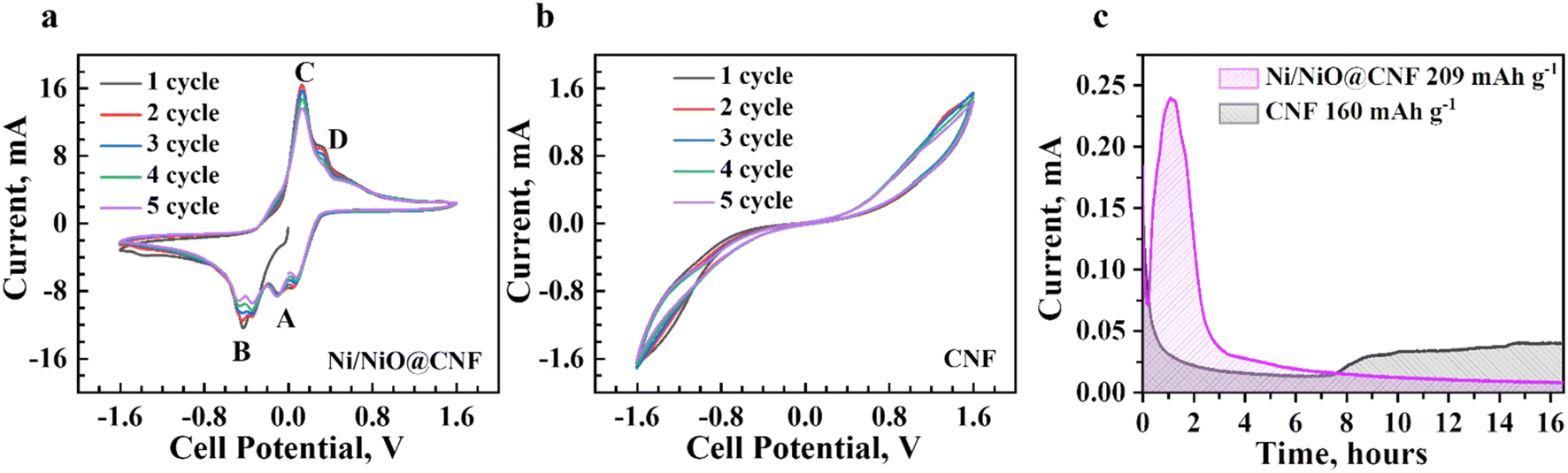
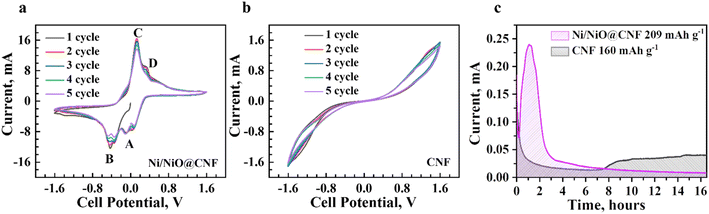
The electrochemical dynamic impact of synthesized materials on the conversion of lithium polysulfides was analysed by cyclic voltammetry with symmetric cells in the range of −1.6 V to 1.6 V. The result indicated that the CV profile of the Ni/NiO@CNF (Fig. 5a) comprised four obvious capacity responses as a pair of distinct cathodic and anodic peaks, which can be designated as the electrochemical reaction of Li2S6 on the electrode. The Li–S cell with the Ni/NiO@CNF (Fig. 5a) displayed peaks corresponding to the electrochemical reactions of Li2S6 on the electrodes at: −0.102 V (peak A), −0.352 V (peak B), 0.132 V (peak C), and 0.339 V (peak D). The formation of Peak A was caused by the reduction of S to Li2S6; peak B corresponded to the reduction of Li2S6 on the working electrode and oxidation on the counter electrode; peak C arose from the reconstitution of Li2S6 by the oxidation of Li2S2/Li2S on the working electrode; peak D can be specified as the oxidation of Li2S6 generating elemental sulfur, S8, on the working electrode.24 During the electrochemical reaction of Li2S6 on the electrode, the Ni/NiO@CNF showed a more obvious peak current and a better separation of the peaks compared with the CNF (Fig. 5b), indicating the more enhanced kinetics of liquid–liquid reaction occurring on the surface of the Ni/NiO@CNF.25 Meanwhile, there were no peaks exhibited for the CNF, but separate CV curves demonstrated stable maintenance of five cycles, determining the good reversibility of reactions. Nevertheless, further analysis of the kinetic behaviour towards lithium polysulfide reduction was carried out via the Li2S precipitation experiments (nucleation test) (Fig. 5c). Potentiostatic discharge curves of 0.05 Li2S6 were collected with respect to the equilibrium potential that drives the nucleation of sulfur species. Current integral calculations were estimated to be 160 mA h g−1 and 209 mA h g−1 of specific capacity for the CNF and Ni/NiO@CNF, respectively, based on the Li2S precipitation integrating area. From these results, it can be seen that the use of Ni/NiO NPs into the structure of carbon nanofibers provides better LiPS transition to Li2S with its induced nucleation and conversion, thus decreasing the possibilities of LiPS dissolution and diffusion on the anodic side. Moreover, the Ni/NiO@CNF clearly demonstrated the most favourable effect on the Li2S precipitation, thus confirming the exceptional electrochemical activity towards LiPSs in better promoting their redox reactions.
 |
| | Fig. 5 Kinetic behaviour analysis of the synthesized carbon nanofiber mats' CV measurements investigated with symmetric cells at a scan rate of 0.5 mV s−1: (a) Ni/NiO@CNF; (b) CNF; and (c) Li2S nucleation test. | |
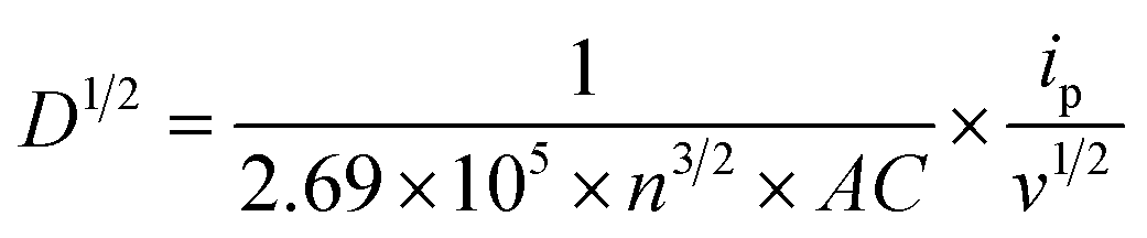
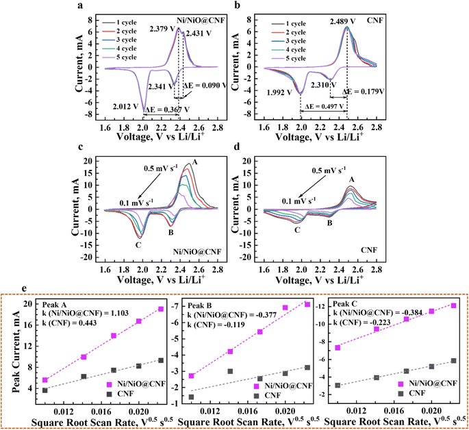
The CV profiles of Li–S cells with Li chips presented apparent reduction and oxidation peaks in the designated potential regions (Fig. 6a–d). The implementation of the Ni/NiO@CNF managed to reduce the polarity of Li–S cells (Fig. 6a), decrease the potential range between peaks during charge and discharge processes, and stabilise them obtaining narrower peaks with similar, more profound current outcomes. Moreover, a sharp peak of S8 transference into Li2S8/Li2S6 and, eventually, to Li2S4 during the first stage of the discharge process was decreased with an alternatively deepened peak of polysulfide conversion into Li2S2/Li2S, the final step of discharge. This behaviour demonstrated fast and effective conversion of polysulfides, thus relenting the ‘shuttle effect’ and better utilizing the active material. Meanwhile, the Ni/NiO@CNF displayed two different effects on the polysulfide retention during the charging process: the Ni/NiO@CNF cell exhibited a sharper peak of the oxidation reaction of transferring Li2S2/Li2S into long-chained Li2S4/Li2S6/Li2S8 and with subsequent formation of sulfur in the octet step. Besides, the Li–S cell with just CNF provided good reversibility of cycles but higher polarization and higher current difference between reduction and oxidation peaks (Fig. 6b). Therefore, NiO NPs helped deposit polysulfides during discharging and effectively used them at the charge stage, while the impact of Ni NPs was prompter, accelerating the latter stages of the oxidation reaction.26,27 In order to evaluate the reaction kinetics of both materials, additional CV analysis at multiple scanning rates from 0.5 to 0.1 mV s−1 was carried out to estimate the diffusion of lithium ions within the current collectors (Fig. 6c and d).28–30 The CV plots of the CNF and Ni/NiO@CNF had fitted slope values for the A, B, and C redox reactions that were linear with the square root of scanning rates, indicating a diffusion-limited mechanism (Fig. 6e), according to the Randles–Sevcik equation as follows:
| ip = (2.69 × 10⁵)n3/2ACD1/2v1/2 |
where
ip is the peak current (A),
n the electron stoichiometry,
A the electrode area (cm
2),
C the concentration (mol cm
−3),
D the diffusion coefficient (cm
2 s
−1), and
v the scan rate (V s
−1).
11 Therefore, the diffusion coefficient of lithium ions will be as follows:
where
ip/
v1/2 represents the slope of the curve and is linearly dependent on the diffusion coefficient. The higher the slope in terms of O
x and O
y axes, the higher the lithium-ion diffusivity at the peaks A and C. It is evident that the Ni/NiO@CNF sample had the highest lithium-ion diffusivity, which is mostly due to the better LiPS adsorption and improved kinetics of LiPS conversion into Li
2S
2/Li
2S.
 |
| | Fig. 6 Reactions kinetics of the conversion of lithium polysulfides investigated by cyclic voltammetry of Li–S cells at 0.1 mV s−1 scan speed: (a) Ni/NiO@CNF and (b) CNF. Cyclic voltammetry at different scanning rates (0.5–0.1 mV s−1): (c) Ni/NiO@CNF; (d) CNF; and (e) linear fits of peak currents. | |
3.4
In situ Raman analysis
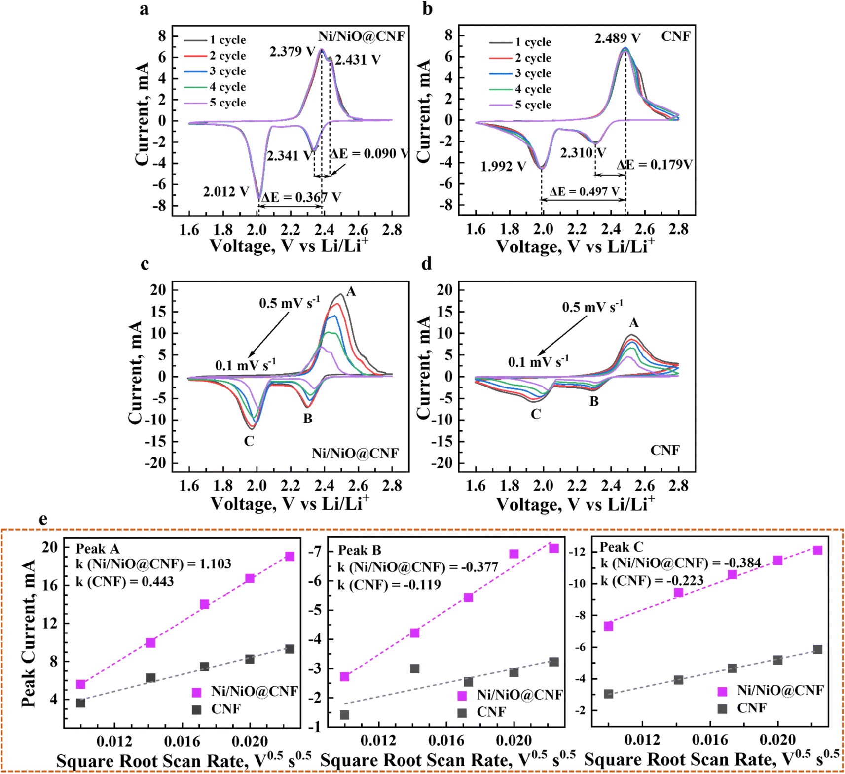
In situ Raman spectroscopy analysis of the Ni/NiO@CNF and CNF impacts on the lithium polysulfide conversion was investigated, relying on the change in charge and discharge potentials during the cyclic voltammetry process. Li–S cells were assembled with a hole on the center of one cap sealed by a glass layer. Interpretations of the potential signals rising from the chemical interactions between LiPSs and CNFs, and Ni/NiO@CNFs on the Raman spectra are presented in Fig. 7. At a starting potential point of 2.45 V, three main sharp peaks corresponding to S42− (240 and 440 cm−1), S62− (420 cm−1), and S82− and (470 cm−1) for both the CNF and Ni/NiO@CNF. As the batteries underwent further discharging till 1.60 V, the intensities of the mentioned peaks began shrinking with the increase in the intensities of S22− and S8 peaks at 150 cm−1, 220 cm−1, and 470 cm−1 of Raman shifts. Meanwhile, the extent of S62− peaks became less apparent in the case of Ni/NiO@CNF (Fig. 7a) during the second reduction step of converting LiPSs into Li2S2/Li2S between discharge potentials of 2.00 V and 1.80 V in contrast to the CNF (Fig. 7b). The sharper decrease in intensity indicates the faster kinetics of LiPS transfer into insoluble simplified sulfur species, Li2S2/Li2S, which greatly contributes to the efficient utilization of the active materials and, thus, improving overall electrochemical performance. After finishing the discharge stage and moving to the charge step, Raman signals of S42−, S62−, and S82− reappeared starting from 1.80 V charge potential point for the Ni/NiO@CNF, while signals for the CNF demonstrated less efficient LiPS conversion keeping the extent of the LiPS peaks idle by the end of the whole cycle. Thus, the incorporation of Ni/NiO NPs into CNF provided with major contributions with enhanced reaction kinetics and efficient utilization of the active material.
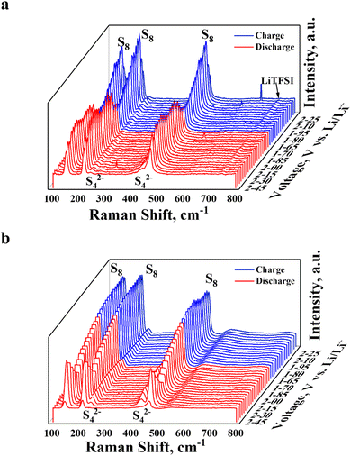 |
| | Fig. 7
In situ Raman analysis of Li–S cells on the comparative formation of sulfur species during cycling voltammetry at 0.5 mV s−1 scan speed: (a) Ni/NiO@CNF and (b) CNF. | |
3.5 Potentiostatic electrochemical impedance spectroscopy analysis
Further, the electrochemical behaviour of Li–S cells was investigated by potentiostatic electrochemical impedance spectroscopy (PEIS) before and after five CV cycles. In Fig. 8, the PEIS spectra demonstrated semicircles in the medium frequency region alongside straight lines in the low-frequency area. Semicircles correspond to the charge transfer resistance (Rct) and processes at the interface of the cathode material and electrolytes, while straight lines define Warburg Resistance (WO)31,32. As demonstrated in Fig. 8, the decrease in Rct with the Ni/NiO@CNF mat (33.0 Ω) compared to the CNF (48.5 Ω) was due to the use of carbon nanofibers with Ni/NiO polar nanoparticles that, therefore, decreased the internal resistance of Li–S batteries. After five cycles, Rct of both Li–S cells became lower in contrast to freshly assembled batteries (7 Ω and 22.0 Ω for Ni/NiO@CNF and CNF, respectively), meaning the continuous deposition of insoluble and non-conductive Li2S/Li2S2 on the surface of the carbon nanofibers. Moreover, the lower Rct enables better Li+ migration, which results in improved cycling stability of carbon nanofiber mats.32 Besides, it further confirms better polysulfide kinetics during the redox reactions caused by carbon nanofibers, a conductive material with long electron transfer paths.
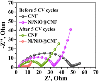 |
| | Fig. 8 Potential electrochemical impedance spectroscopy of Li–S. | |
3.6 Electrochemical performance analysis of Li–S cells with CNFs and Ni/NiO@CNFs
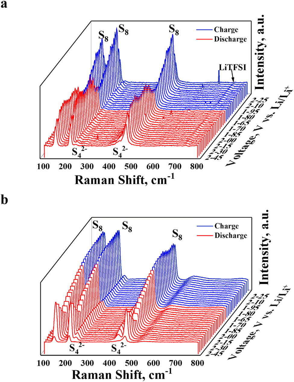
The galvanostatic charge–discharge cycle of assembled Li–S cells with CNF and Ni/NiO@CNF mats and a sulfur loading of ∼2.0 mg cm−2 was employed to investigate the cycles reversibility and overall electrochemical performance at 0.5 and 1.0C rates. In addition, the rate capability charge–discharge cycling test was carried out to determine the extent of specific capacity retention at different current densities in a row. According to the results in Fig. 9a, the Ni/NiO@CNF cell demonstrated lower polarisation during charge–discharge cycling exhibiting 1401.9 mA h g−1, 1164.6 mA h g−1, 870.1 mA h g−1, and 691.6 mA h g−1 of specific capacities at 0.2C, 0.5C, 1.0C, and 2.0 rates, correspondingly. Decreasing the current density from 2.0C to 0.5C and 0.2C resulted in retrieving similar specific capacities the cells had in the beginning of these tests. Meanwhile, the CNF cell delivered 1102.05 mA h g−1, 884.6 mA h g−1, 524.1 mA h g−1, and 336.5 mA h g−1 of specific capacities at 0.2C, 0.5C, 1.0C, and 2.0C rates, respectively. However, this cell exhibited less capacity retention after decreasing the current rates to 0.5C (617.9 mA h g−1) and 0.2C (954.4 mA h g−1) in the end.
 |
| | Fig. 9 Galvanostatic charge–discharge cyclability results: (a) rate capability recordings; (b) 0.5C rate cyclability; and (c) 1.0C rate cyclability. Voltage profiles: (d) Ni/NiO@CNFs and (e) CNFs. | |
The charge–discharge cycles of the Ni/NiO@CNF cell at 0.5C and 1.0 rates delivered 1335.1 mA h g−1 and 1190.4 mA h g−1 of initial specific capacity at 0.5C and 1.0C, retrieving 77% and 70% of capacity retention after 100 and 200 cycles, respectively. Meantime, the cell with CNFs exhibited a high initial specific capacity of 1026.4 mA h g−1 at 0.5C rate, though with only 65% of capacity retention after 100 cycles (Fig. 9b and c). A relatively stable capacity retention at 0.5C rate for the CNF cell can be explained by a higher surface area and a higher cumulative pore volume, which are great contributors to LiPS entrapping and their more uniform utilization. Nevertheless, at a higher current density, the cell with the Ni/NiO@CNF exhibited greater capacity and stronger cycling stability than the cell with the CNF, which can be addressed to the improved reaction kinetics owing greatly to Ni NPs and the enhanced adsorptive effect of NiO NPs. Besides, longer plateaus at 0.5C rate recorded charge–discharge voltage profiles of the cell with the Ni/NiO@CNF (Fig. 9d), in contrast to the CNF (Fig. 9e), indicating improved polysulfide adsorption and prompter conversion of initial sulfur species, S8 and Li2S, into polysulfides during discharge and, vice versa, during charge processes.
3.7 Post-cycling SEM analysis
To investigate the morphological changes of carbon nanofibers after exposure to lithium polysulfides during cycling, the cells with the CNF and Ni/NiO@CNF were disassembled after 100 cycles of charge–discharge and the retrieved carbon nanofibers mats were investigated by SEM. According to the findings, Ni/NiO@CNF nanofibers were uniformly covered with molten sulfur species (Fig. 10a), while their agglomerations were discovered on the surface of the CNF (Fig. 10b). The absence or less extent of the mentioned agglomerations indicates that LiPSs were uniformly utilized by the Ni/NiO@CNF, mostly owing to the auxiliary adsorptive effect of NiO NPs and the improved kinetics by Ni NPs.
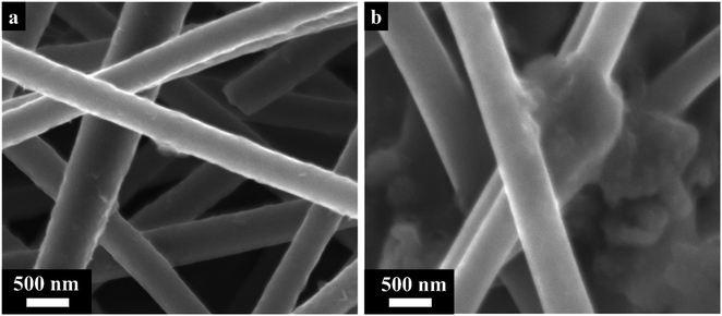 |
| | Fig. 10 Post-cycling SEM morphology analysis images: (a) Ni/NiO@CNFs and (b) CNFs. | |
4. Conclusions
The assistance impact analysis of Ni/NiO NPs on lithium polysulfide retention by CNF mats has been investigated. The results indicated that the application of CNFs and Ni/NiO@CNFs caused a beneficial effect on the kinetics of lithium polysulfide electrochemical reduction and oxidation processes. Moreover, the CNF and Ni/NiO@CNF strengthened the electron pathway by effectively utilizing the active material at a high sulfur loading of 2 mg cm−2. Nevertheless, the Ni/NiO@CNF exhibited greater initial specific capacities of 1335.1 mA h g−1 and 1190.4 mA h g−1, while CNF retrieved only 1026.4 mA h g−1 and 672.7 mA h g−1 at 0.5 and 1.0C rates, respectively. In addition, the Ni/NiO@CNF composite demonstrated higher cycle reversibility even at 1.0C rate with 70% capacity retention after 200 cycles in contrast to the CNF with 31%. The increased stability of the Ni/NiO@CNF composite was due to more effective LiPS retaining, providing additional NiO active sites for depositing discharged products of the electrochemical process and decreasing the electron charge transfer resistance thanks to the great catalytic abilities of Ni. Therefore, the application of carbon nanofibers functionalized with Ni/NiO NPs is an effective and promising approach for fabricating a long-life lithium–sulfur battery.
Conflicts of interest
There are no conflicts to declare.
Acknowledgements
This work was supported by the project AP09259764 “Engineering of Multifunctional Materials of Next-Generation Batteries” from the Ministry of Education and Science of the Republic of Kazakhstan. The Authors deeply appreciate the assistance of JEOL main factory in Akishima, Japan, for analysing our carbon nanofibers samples on the JEM-ARM200F “NeoARM” TEM equipment.
References
- Y. Li, J. G. Shapter, H. Cheng, G. Xu and G. Gao, Recent progress in sulfur cathodes for application to lithium–sulfur batteries, Particuology, 2021, 58, 1–15, DOI:10.1016/j.partic.2021.01.008.
- W. Xu,
et al., A conductive sulfur-hosting material involving ultrafine vanadium nitride nanoparticles for high-performance lithium-sulfur battery, Electrochim. Acta, 2020, 331, 135287, DOI:10.1016/j.electacta.2019.135287.
- Y. Wang, S. Luo, D. Wang, X. Hong and S. Liu, Facile synthesis of three dimensional porous cellular carbon as sulfur host for enhanced performance lithium sulfur batteries, Electrochim. Acta, 2018, 284, 400–407, DOI:10.1016/j.electacta.2018.07.141.
- P. H. Wadekar, A. Ghosh, R. V. Khose, D. A. Pethsangave, S. Mitra and S. Some, A novel chemical reduction/co-precipitation method to prepare sulfur functionalized reduced graphene oxide for lithium-sulfur batteries, Electrochim. Acta, 2020, 344, 136147, DOI:10.1016/j.electacta.2020.136147.
- Y. V. Mikhaylik and J. R. Akridge, Polysulfide Shuttle Study in the Li/S Battery System, J. Electrochem. Soc., 2004, 151(11), A1969, DOI:10.1149/1.1806394.
- M. Wang,
et al., Porous Carbon Hosts for Lithium–Sulfur Batteries, Chem.—Eur. J., 2019, 25(15), 3710–3725, DOI:10.1002/chem.201803153.
- Z. Cao,
et al., In situ self-boosting catalytic synthesizing free-standing N, S rich transition metal sulfide/hierarchical CNF-CNT architectures enable high-performance lithium-sulfur batteries, Electrochim. Acta, 2022, 422, 140549, DOI:10.1016/j.electacta.2022.140549.
- C. H. Kim, B. H. Kim and K. S. Yang, TiO 2 nanoparticles loaded on graphene/carbon composite nanofibers by electrospinning for increased photocatalysis, Carbon, 2012, 50(7), 2472–2481, DOI:10.1016/j.carbon.2012.01.069.
- T. Ould Ely, D. Kamzabek, D. Chakraborty and M. F. Doherty, Lithium-Sulfur Batteries: State of the Art and Future Directions, ACS Appl. Energy Mater., 2018, 1(5), 1783–1814, DOI:10.1021/acsaem.7b00153.
- H. B. Kim,
et al., Vanadium nitride and carbon nanofiber composite membrane as an interlayer for extended life cycle lithium-sulphur batteries, Ceram. Int., 2021, 47(15), 21476–21489, DOI:10.1016/j.ceramint.2021.04.159.
- N. Mosavati, S. O. Salley and K. Y. S. Ng, Characterization and electrochemical activities of nanostructured transition metal nitrides as cathode materials for lithium sulfur batteries, J. Power Sources, 2017, 340, 210–216, DOI:10.1016/j.jpowsour.2016.11.033.
- J. Zhu,
et al., Hybrid TiO-TiO2 nanoparticle/B-N co-doped CNFs interlayer for advanced Li–S batteries, J. Electroanal. Chem., 2021, 881, 114950, DOI:10.1016/j.jelechem.2020.114950.
- C. Qi, Z. Li, C. Sun, C. Chen, J. Jin and Z. Wen, Cobalt Phosphide Nanoflake-Induced Flower-like Sulfur for High Redox Kinetics and Fast Ion Transfer in Lithium-Sulfur Batteries, ACS Appl. Mater. Interfaces, 2020, 12(44), 49626–49635, DOI:10.1021/acsami.0c14260.
- C. Wei,
et al., Flexible NiCo2S4-hollow carbon nanofibers electrocatalytic membrane as an advanced interlayer for lithium-sulfur batteries, Colloids Surf., A, 2022, 648, 129179, DOI:10.1016/j.colsurfa.2022.129179.
- M. Chen,
et al., Kinetically elevated redox conversion of polysulfides of lithium-sulfur battery using a separator modified with transition metals coordinated g-C3N4 with carbon-conjugated, Chem. Eng. J., 2020, 385, 123905, DOI:10.1016/j.cej.2019.123905.
- U. K. Fatema, A. J. Uddin, K. Uemura and Y. Gotoh, Fabrication of carbon fibers from electrospun poly(vinyl alcohol) nanofibers, Text. Res. J., 2011, 81(7), 659–672, DOI:10.1177/0040517510385175.
- L. Wang, C. Shi, L. Pan, X. Zhang and J. J. Zou, Rational design, synthesis, adsorption principles and applications of metal oxide adsorbents: A review, Nanoscale, 2020, 12(8), 4790–4815, 10.1039/c9nr09274a.
- Y. Koshtyal,
et al., Atomic layer deposition of nio to produce active material for thin-film lithium-ion batteries, Coatings, 2019, 9(5), 301, DOI:10.3390/coatings9050301.
- X. Chen, H. Zhang, P. Yan, X. Cao, C. Zhan and J. H. Liu, Flower-like metal oxide composite as an efficient sulfur host for stable and high-capacity lithium-sulfur batteries, J. Solid State Chem., 2022, 314, 123430, DOI:10.1016/j.jssc.2022.123430.
- S. Kalybekkyzy, A. Mentbayeva, Y. Yerkinbekova, N. Baikalov, M. V. Kahraman and Z. Bakenov, Electrospun 3D structured carbon current collector for Li/S batteries, Nanomaterials, 2020, 10(4), 1–13, DOI:10.3390/nano10040745.
- S. Li,
et al., Cobalt-embedded carbon nanofiber as electrocatalyst for polysulfide redox reaction in lithium sulfur batteries, Electrochim. Acta, 2019, 304, 11–19, DOI:10.1016/j.electacta.2019.02.087.
- S. Yao,
et al., TiO2 nanoparticles incorporation in carbon nanofiber as a multi-functional interlayer toward ultralong cycle-life lithium-sulfur batteries, J. Alloys Compd., 2019, 788, 639–648, DOI:10.1016/j.jallcom.2019.02.236.
- Z. Zhang, A. H. Shao, D. G. Xiong, J. Yu, N. Koratkar and Z. Y. Yang, Efficient Polysulfide Redox Enabled by Lattice-Distorted Ni3Fe Intermetallic Electrocatalyst-Modified Separator for Lithium-Sulfur Batteries, ACS Appl. Mater. Interfaces, 2020, 12(17), 19572–19580, DOI:10.1021/acsami.0c02942.
- Z. Du,
et al., Cobalt in Nitrogen-Doped Graphene as Single-Atom Catalyst for High-Sulfur Content Lithium-Sulfur Batteries, J. Am. Chem. Soc., 2019, 141(9), 3977–3985, DOI:10.1021/jacs.8b12973.
- S. Yang,
et al., Ni2P electrocatalysts decorated hollow carbon spheres as bi-functional mediator against shuttle effect and Li dendrite for Li-S batteries, Nano Energy, 2021, 90, 106584, DOI:10.1016/j.nanoen.2021.106584.
- J. Wu, Q. Ma, C. Lian, Y. Yuan and D. Long, Promoting polythionate intermediates formation by oxygen-deficient manganese oxide hollow nanospheres for high performance lithium-sulfur batteries, Chem. Eng. J., 2019, 370, 556–564, DOI:10.1016/j.cej.2019.03.078.
- S. Huang,
et al., Regulating the polysulfide redox conversion by iron phosphide nanocrystals for high-rate and ultrastable lithium-sulfur battery, Nano Energy, 2018, 51, 340–348, DOI:10.1016/j.nanoen.2018.06.052.
- D. Wang,
et al., A freestanding metallic tin-modified and nitrogen-doped carbon skeleton as interlayer for lithium-sulfur battery, Chem. Eng. J., 2020, 399, 125723, DOI:10.1016/j.cej.2020.125723.
- V. Marangon,
et al., Current collectors based on multiwalled carbon-nanotubes and few-layer graphene for enhancing the conversion process in scalable lithium-sulfur battery, Nano Res., 2023, 16(6), 8433–8447, DOI:10.1007/s12274-022-5364-5.
- M. Chen,
et al., Honeycomb-like Nitrogen and Sulfur Dual-Doped Hierarchical Porous Biomass-Derived Carbon for Lithium–Sulfur Batteries, ChemSusChem, 2017, 10(8), 1803–1812, DOI:10.1002/cssc.201700050.
- L. Kong, Y. Handa and I. Taniguchi, Synthesis and characterization of sulfur-carbon-vanadium pentoxide composites for improved electrochemical properties of lithium-sulfur batteries, Mater. Res. Bull., 2016, 73, 164–170, DOI:10.1016/j.materresbull.2015.08.036.
- H. Shao, W. Wang, H. Zhang, A. Wang, X. Chen and Y. Huang, Nano-TiO2 decorated carbon coating on the separator to physically and chemically suppress the shuttle effect for lithium-sulfur battery, J. Power Sources, 2018, 378, 537–545, DOI:10.1016/j.jpowsour.2017.12.067.
|
| This journal is © The Royal Society of Chemistry 2024 |
Click here to see how this site uses Cookies. View our privacy policy here. 
 Open Access Article
 This Open Access Article is licensed under a Creative Commons Attribution-Non Commercial 3.0 Unported Licence
 b,
Aishuak
Konarov
b,
Aishuak
Konarov