 Open Access Article
Creative Commons Attribution 3.0 Unported Licence
Triplet–triplet annihilation-based photon upconversion using nanoparticles and nanoclusters
Yoshiki
Niihori
 *a,
Taiga
Kosaka
b and
Yuichi
Negishi
 *abc
*abc
aResearch Institute for Science and Technology, Tokyo University of Science, 1-3 Kagurazaka, Shinjuku-ku, Tokyo 162-8601, Japan. E-mail: niihori@rs.tus.ac.jp; negishi@rs.tus.ac.jp
bGraduate School of Science, Department of Chemistry, Tokyo University of Science, 1-3 Kagurazaka, Shinjuku-ku, Tokyo 162-8601, Japan
cDepartment of Applied Chemistry, Faculty of Science, Tokyo University of Science, 1-3 Kagurazaka, Shinjuku-ku, Tokyo 162-8601, Japan
First published on 26th March 2024
Abstract
The phenomenon of photon upconversion (UC), generating high-energy photons from low-energy photons, has attracted significant attention. In particular, triplet–triplet annihilation-based UC (TTA-UC) has been achieved by combining the excitation states of two types of molecules, called the sensitizer and emitter (or annihilator). With TTA-UC, it is possible to convert weak, incoherent near-infrared (NIR) light, which constitutes half of the solar radiation intensity, into ultraviolet and visible light that are suitable for the operation of light-responsive functional materials or devices such as solar cells and photocatalysts. Research on TTA-UC is being conducted worldwide, often employing materials with high intersystem crossing rates, such as metal porphyrins, as sensitizers. This review summarizes recent research and trends in triplet energy transfer and TTA-UC for semiconductor nanoparticles or nanocrystals with diameters in the nanometer range, also known as quantum dots, and for ligand-protected metal nanoclusters, which have even smaller well-defined sub-nanostructures. Concerning nanoparticles, transmitter ligands have been applied on the surface of the nanoparticles to efficiently transfer triplet excitons formed inside the nanoparticles to emitters. Applications are expanding to solid-state UC devices that convert NIR light to visible light. Additionally, there is active research in the development of sensitizers using more cost-effective and environmentally friendly elements. Regarding metal nanoclusters, methods have been established for the evaluation of excited states, deepening the understanding of luminescent properties and excited relaxation processes.
Wider impactThe imperative to acquire clean energy sources is underscored by the impacts of global warming. Solar radiation is an attractive energy source because it is abundantly available on Earth's surface; however, most materials and devices are driven by ultraviolet and visible light, leaving the near-infrared (NIR) sunlight untapped. Triple–triplet annihilation upconversion (TTA-UC) is an energy conversion technique that uses a combination of sensitizer and emitter molecules to convert the underutilized NIR light into visible light that is usable in devices. In particular, inorganic nanomaterials, such as semiconductor nanoparticles with sizes around a few nanometers and ligand-protected metal nanoclusters with precisely defined compositions, have been identified for their ability to sensitize the excited triplet states of emitter molecules. These inorganic nanomaterials, with tunable electronic states based on their size and composition, exhibit broad absorption bands in the NIR region. The application of these inorganic nanomaterials for highly efficient NIR upconversion is expected to improve the performance of solar harvesting devices, surpassing the TTA-UC capabilities of conventional organic sensitizers and maximizing the use of incoming solar rays. |
1. Introduction
The Earth's surface receives approximately 0.1 W cm−2 of solar radiation, consisting mainly of ultraviolet (UV), visible, and near-infrared (NIR) light. Attempts to harness this abundant solar energy to enrich human life have a history dating back approximately 10,000 years with the invention of agriculture.1 This effort continued through the advent of solar water heaters in ancient Greece and Rome and evolved into modern technologies that convert solar energy into electricity or chemical energy.Since the Industrial Revolution, the deterioration of the environment due to the consumption of fossil fuels has sparked demand for the development of materials and energy sources with lower environmental impact. In particular, materials and devices that exploit solar energy, such as photocatalysts and solar cells, for driving material transformations or converting energy into electricity align with this goal. More efficient versions of these optical materials and devices are continually being developed. The mechanisms of these materials and devices start with the formation of electron-excited states, which requires UV and visible light with energies of several electron volts. However, approximately half of the solar radiation reaching the Earth's surface consists of lower-energy NIR light. Currently, efficiently creating electron-excited states from NIR light is challenging, and as a result, humanity has not developed the technology to fully harness the solar spectrum.
In recent years, the phenomenon of upconversion (UC) has garnered attention as a promising method to overcome this challenge. The conversion from low-energy states to high-energy states is known as UC, and in the context of light energy, it is referred to as photon UC. Various methods, such as the use of rare earth compounds and two-photon absorption, have been employed to achieve optical UC.2–5 In particular, triplet–triplet annihilation-based photon UC (TTA-UC), which leverages the reactions between the excitation states of sensitizer and emitter molecules, has been proposed to convert weak incoherent NIR light from solar radiation into UV and visible light.6,7
While metalloporphyrins and other phosphorescent materials are representative sensitizers in TTA-UC, recent advancements have revealed the potential use of semiconductor quantum dots consisting of sizes ranging from several to tens of nanometers. More recently, the potential of ligand-protected metal nanoclusters composed of a finite number of noble metal atoms as sensitizers in TTA-UC has also been identified.
To date, numerous sensitizing molecules based on organic metal complexes have been developed for TTA-UC, and several reviews have been published.8–14 Similarly, inorganic nanomaterials that are capable of interacting with light across a wide range of wavelengths have gained attention as sensitizing molecules. Theoretical discussions unique to nanomaterials, such as those regarding excitons and efficient energy transfer through triplet transmitters, have been established. In addition, Meinardi, Mongzzi, and their coworkers have also developed a detailed kinetic analysis method for systems consisting of transmitter-modified nanoparticle sensitizers and emitters.15 However, comprehensive reviews focusing on their triplet sensitization and application to TTA-UC are scarce.16
This review compiles research on the performance of inorganic nanomaterials as sensitizers and their application to TTA-UC, ranging from nanoscale particles and nanocrystals to even smaller nanoclusters. Through this compilation, we aim to discuss the current understanding, challenges, and prospects for future research.
In Chapter 2, we first introduce the mechanism of TTA-UC and the physical quantities to be obtained. Subsequently, in Chapter 3, we discuss the triplet sensitization and TTA-UC performance of homogenous nanoparticles, core–shell nanoparticles, perovskite nanocrystals, and metal-free nanoparticles with sizes on the order of several nanometers. In Chapter 4, we extend our discussion to sub-nanometer-sized nanoclusters composed of noble metals, covering their triplet sensitization, TTA-UC characteristics, and the excited states of the metal nanoclusters themselves. After summarizing the review in Chapter 5, we conclude the review by discussing future perspectives in Chapter 6. We hope that this review facilitates mutual understanding among researchers in the fields of UC and inorganic nanomaterials.
2. Fundamentals of TTA-UC
Mechanism of TTA-UC
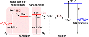
TTA-UC is achieved using two types of molecules: the triplet sensitizer (Sen) and the emitter/annihilator (Em). The proposed mechanism is illustrated in Scheme 1. Initially, the sensitizer molecule in the ground (S0) state (1Sen) absorbs light, leading to the formation of the excited singlet (S1) state (1Sen*). Subsequently, through intersystem crossing (ISC), the long-lived excited triplet (T1) state (3Sen*) is generated. It should be noted that while this process provides an accurate description for general sensitizers represented by metalloporphyrin complexes and the inorganic nanoclusters to be introduced later, in the case of inorganic nanoparticles, an excited state of sensitizer (Sen*) characterized as a mixed state of the S1 and T1 states is formed. Consequently, the energy loss due to intersystem crossing (ISC) is minimized in inorganic nanoparticles. This persistent 3Sen* or Sen* molecule sensitizes the T1 state of the emitter molecule in the S0 state (1Em → 3Em*) via Dexter-type triplet energy transfer (TET). Subsequently, triplet–triplet annihilation (TTA) occurs between the two 3Em* molecules, resulting in one emitter transitioning to the S0 state and the other to the S1 state (1Em*). Finally, the fluorescence (F) photon is emitted as UC fluorescence from 1Em*. The emission spectrum of these UC photons exhibits a similar shape to the emission spectrum obtained when directly exciting the emitter. However, in the emission process of UC photons through TTA-UC, involving the T1 state of the emitter, the UC is observed as delayed fluorescence, reflecting the T1 lifetime of the emitter.17In this manuscript, we primarily focus on solution-based systems involving molecules dissolved in a solvent. We denote the solution system consisting of the sensitizer and emitter as “Sen/Em.” Additionally, we represent complexes where some of the protective ligands on the sensitizer surface are replaced with transmitter ligands (Trans) as “Sen:Trans” and further denote solution systems combining this complex with the emitter as “Sen:Trans/Em.”
Anti-Stokes Shift
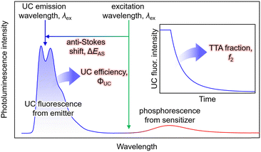
In typical single-component fluorescent dyes, the emission peak is observed at a longer wavelength than the excitation wavelength. The energy difference between the absorption peak and the emission peak, expressed in units of cm−1 or eV, is known as the Stokes shift, providing information about the molecule's excited state. Conversely, in TTA-UC, the observed UC wavelength is shorter than the excitation photon wavelength (Fig. 1). The difference between the excitation photon energy and the UC photon energy, analogous to the Stokes shift, is referred to as the anti-Stokes shift (ΔEAS) (Fig. 1), and is described as follows: | (1) |
The estimation of λUC can vary in the literature, using the peak wavelength or centroid wavelength of the UC spectrum. TTA-UC experiments are often conducted under conditions where the concentrations of Sen and Em ([Sen] and [Em]) are in the range of several tens of μM to several tens of mM. Under such high concentrations, when using fluorescent dyes with small Stokes shifts, such as perylene or acene-based dyes as emitters, self-absorption, also known as self-quenching, occurs where the fluorescence peak near the 0–0 transition energy is absorbed by the emitter. Consequently, a decrease in ΔEAS is observed. Therefore, the value of ΔEAS depends on the sample concentration, sample form, and experimental setup, including the position of the excitation light irradiation.
UC efficiency
The UC efficiency (ΦUC) is the ratio of the number of detected UC emitting photons to the number of absorbed photons, defined by the following equation: | (2) |
Similar to the conventional fluorescence quantum yield (ΦF), ΦUC can be experimentally evaluated using either a relative method with standard dyes or an absolute method employing an integrating sphere (Fig. 1).18
Because TTA-UC involves reactions within/between two excited-state molecules, ΦUC can be expressed as the product of the quantum yields of each subprocess. There are various ways to express this, but we use the following unified expression:
| ΦUC = ΦISC·ΦTET·ΦTTA·ΦF. | (3) |
 :
: | (4) |
As mentioned later, experimentally obtained ΦUC and  depend on the concentrations of the sensitizer and emitter, as well as the intensity of the excitation light.
Furthermore, several literatures discuss the consideration of the quenching effect of UC fluorescence due to the presence of high concentration of emitters (internal filter effect), termed ΦUCg. This value is obtained experimentally by dividing ΦUC by the optical outcoupling yield of the sample (Φout).19
 | (5) |
The Φout can be derived from transmittance spectrum of TTA-UC sample solution and fluorescence spectrum of low concentration solution of emitter excited under normal condition.
TET efficiency
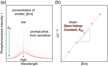
For the Sen/Em system, determining the phosphorescence quenching of the sensitizer due to the addition of the emitter allows for the calculation of the TET efficiency (ΦTET) through Stern–Volmer analysis, as depicted in Fig. 2. The relationship between the Stern–Volmer constant (KSV) and ΦTET is expressed as follows:20 | (6) |
Thus, ΦTET is a function of the emitter concentration [Em]. The rate constant kTET for TET can be estimated by dividing KSV by the phosphorescence lifetime (τPL) in the absence of the emitter:
 | (7) |
TET involves Dexter-type energy transfer, and its rate constant can be discussed using Marcus theory. Specifically, considering the sensitizer and emitter as the donor and acceptor of triplet energy, respectively, kTET is described as follows:21
 | (8) |
In this equation, ΔG° represents the energy difference between the T1 states of both molecules, |J| is the electron coupling constant between the donor and acceptor, and λ signifies the reorganization energy.
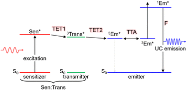
Moreover, as illustrated in Scheme 2, when using nanoparticles as sensitizers, it is possible to efficiently transfer triplet energy to the emitter. In such cases, triplet energy transmitter ligands may be introduced onto the nanoparticle surface and additional free emitters may be added (Sen:Trans/Em). In this scenario, the overall TET comprises the first stage from the nanoparticle to the transmitter (TET1) and the second stage from the transmitter to the emitter (TET2). The overall ΦTET is the product of ΦTET1 and ΦTET2. TET1 can be evaluated using transient absorption spectroscopy or phosphorescence lifetime measurements.
TTA efficiency
Although its definition may vary across different references, the term ΦTTA is defined here as the probability of generating 1Em* through the collision of 3Em* molecules. Thus, ΦTTA is expressed as the product of the spin statistical factor (fspin) and the fraction (f2) of the 3Em* molecules generated by TET that are consumed in the deactivation processes, leading to TTA (ΦTTA = 1/2fspin·f2). The value of f2 is obtained by fitting the decay of the UC intensity based on kinetic considerations (Fig. 1, inset).22–24 TTA involves reactions between triplet-sensitized 3Em* molecules, and considering that it constitutes the latter part of the TTA-UC process, it is heavily dependent on the characteristics of the emitter molecules. As this review predominantly focuses on the triplet sensitization capability of the sensitizer in the first half of the TTA-UC process, detailed information about TTA may be referred to in other reports.23,24Excitation intensity threshold
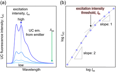
The TTA-UC process, being a bimolecular process, exhibits secondary behavior concerning the excitation light intensity (Iex) in the low excitation intensity regime. However, efficient generation of 3Em* occurs in the high excitation intensity regime, and TTA behaves in a pseudo-first-order manner. Therefore, plotting IUC against Iex shows a transition from secondary to primary behavior as Iex increases (Fig. 3; in a log–log plot with the logarithm of Iex on the horizontal axis and the logarithm of IUC on the vertical axis, the slope of the plot gradually changes from 2 to 1). The excitation light intensity at this transition is referred to as the excitation intensity threshold (Ith). Thus, ΦUC depends on the excitation light intensity, increasing with the increase in Iex in the low excitation intensity regime, but reaching a constant value at excitation light intensities above Ith. Ith can be determined by drawing asymptotic lines with slopes of 1 and 2 on a log–log plot of Iexvs. IUC and finding the intersection, as shown in Fig. 3. Alternatively, Ith can be evaluated using fitting functions based on kinetic interpretations.25–27 For efficient energy conversion of low irradiance and incoherent light, such as the NIR light present in sunlight, a low value of Ith is desirable. Theoretically, Ith is expressed as: | (9) |
 is the diffusion coefficient of 3Em*, a0 is the distance between 3Em* molecules in TTA, typically around 1 nm, and
  is the lifetime of 3Em*.28 Achieving lower thresholds for Ith is possible with larger values of these parameters.
General molecules for TTA-UC
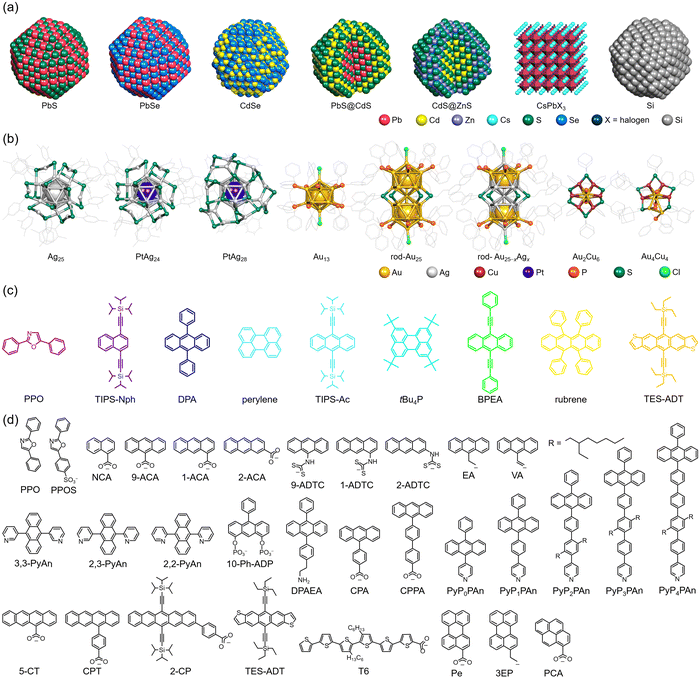
Φ ISC and ΦF represent the unique properties of the sensitizer and emitter, respectively, whereas ΦTET and ΦTTA depend on the combination and concentration of sensitizer and emitter molecules. Therefore, to achieve more efficient TTA-UC, it is necessary to use sensitizers and emitters with a high ΦISC and ΦF (∼1). In many cases, sensitizers with a high ΦISC, large absorption cross-sections, and long excited-state lifetimes, such as phosphorescent materials (e.g., metalloporphyrins), are used, whereas emitters with high fluorescence quantum yields, such as 9,10-diphenylanthracene (DPA), perylene, and rubrene, are chosen. However, to absorb light in the desired NIR range, it is essential to extend the π-conjugated system of the organic sensitizer. In organic synthesis, this often requires complex reactions involving multiple steps, and such organic sensitizers face several challenges: (1) absorbing only specific wavelength ranges, limiting their application to a portion of the wide NIR spectrum in sunlight, and (2) photostability decreasing with the extension of the conjugated system.In this review, the focus is not on organic sensitizers but on inorganic nanoparticles/crystals and nanoclusters composed of metals and semiconductors, which have recently garnered attention. The structures of the inorganic nano-sensitizers, emitters, and transmitter ligands introduced in this review are depicted in Fig. 4. The physical quantities related to TTA-UC with nanoparticles and nanoclusters presented in this review are summarized in Tables 1 and 2, respectively.
| Sensitizera | Transmitter | Emitter | λ ex/nm |
k
TET/s−1![[thin space (1/6-em)]](https://www.rsc.org/images/entities/char_2009.gif) b (ΦTET%) b (ΦTET%) |
ΔEAS/eV | Φ UC%c [ΦUCg%] | I th/mW cm−2 | Ref. |
|---|---|---|---|---|---|---|---|---|
a The values in bracket represent diameter of nanoparticles. For core–shell nanoparticles, the core diameter and shell thickness are separated by “@”.
b In this column, the rate constants kTET and ΦTET (values in (![[thin space (1/6-em)]](https://www.rsc.org/images/entities/char_2009.gif) )) in TET1 or TET2 are indicated.
c The internal UC efficiency (ΦUCg) is described in [ )) in TET1 or TET2 are indicated.
c The internal UC efficiency (ΦUCg) is described in [![[thin space (1/6-em)]](https://www.rsc.org/images/entities/char_2009.gif) ]. Theoretical maximum of both ΦUC and ΦUcg are 50%.
d Absorption energy. The diameter of the nanoparticles was not described in the literature.
e Photoluminescence energy. The diameter of the nanoparticles was not described in the literature.
f The intersystem-crossing rate that converts a spin-singlet state localized on the Si nanoparticle to a spin-triplet state that spatially extends across the Si:9VA interface. ]. Theoretical maximum of both ΦUC and ΦUcg are 50%.
d Absorption energy. The diameter of the nanoparticles was not described in the literature.
e Photoluminescence energy. The diameter of the nanoparticles was not described in the literature.
f The intersystem-crossing rate that converts a spin-singlet state localized on the Si nanoparticle to a spin-triplet state that spatially extends across the Si:9VA interface.
|
||||||||
| PbSe (2.1 nm) | — | Rubrene | 800 | — | 0.92 | 0.005 | ∼6 × 10⁴ | 35 |
| CdSe (2.7 nm) | 9-ACA | DPA | 532 | TET1: 1.5 × 10⁷ | 0.54 | 4.5 | ∼1 × 10⁴ | 35,38 |
| CdSe (2.4 nm) | 9-ACA | DPA | 488 | TET1: 3.8 × 10⁷ | 0.33 | 6.0 | — | 39 |
| 1-ACA | DPA | 488 | TET1: 0.077 × 10⁷ | 0.33 | 1.5 | — | 39 | |
| 2-ACA | DPA | 488 | TET1: 0.063 × 10⁷ | 0.33 | 0.6 | — | 39 | |
| 1-ADTC | DPA | 532 | TET1: 0.075 × 10⁷ | 0.54 | 1.5 | — | 39 | |
| 2-ADTC | DPA | 532 | TET1: 0.063 × 10⁷ | 0.54 | 0.5 | — | 39 | |
| 9-ADTC | DPA | 488 | TET1: 2.7 × 10⁷ | 0.33 | 0.05 | — | 39 | |
| CdSe (3.3 nm) | Pe | tBu4P | 532 | TET1: 3.7 × 10⁸ (47.2) | 0.26 | 3.5 | ∼100 | 40 |
| CdSe (4.2 nm) | Pe | tBu4P | 532 | TET1: 3.4 × 10⁸ (11.4) | 0.26 | 0.28 | ∼2000 | 40 |
| CdTe (3.4 nm) | Pe | tBu4P | 532 | TET1: 4.0 × 10⁸ (25.6) | 0.26 | 1.0 | ∼500 | 40 |
| CdTe (3.7 nm) | Pe | tBu4P | 532 | TET1: 1.2 × 10⁸ (7.51) | 0.26 | 0.09 | ∼1.2 × 10⁴ | 40 |
| CdSe (2.6 nm) | 9-ACA | DPA | 532 | TET1: ∼2.7 × 10⁶ (30.5) | 0.54 | 7.2 | — | 41 |
| CPA | DPA | 532 | TET1: ∼6.6 × 10⁵ (7.8) | 0.54 | 2.0 | — | 41 | |
| CPPA | DPA | 532 | TET1: ∼8.9 × 10⁴ (0.85) | 0.54 | 0.2 | — | 41 | |
| CdSe (2.4 nm) | 2,3-PyAn | DPA | 532 | TET1: 1.28 × 10⁹ (42.0) | 0.54 | 6.1 | 146.8 | 43 |
| TET2: (61.4) | ||||||||
| 3,3-PyAn | DPA | 532 | TET1: 9.62 × 10⁸ (38.1) | 0.54 | 4.1 | — | 43 | |
| TET2: (45.4) | ||||||||
| 2,2-PyAn | DPA | 532 | TET1: 1.25 × 10⁹ (23.1) | 0.54 | 1.3 | — | 43 | |
| TET2: (23.1) | ||||||||
| CdSe (2.4 nm) | 10-Ph-ADP | DPA | 488 | TET1: 1.22 × 10¹¹ (86.4) | 0.34 | 8.5 | 163 | 44 |
| 9-ACA | DPA | 488 | TET1: 5.98 × 10¹⁰ (84.7) | 0.34 | 6.4 | 492 | 44 | |
| PbS (2.9 nm) | CPT | Rubrene | 808 | — | 0.68 | 0.85 | 45 | |
| — | Rubrene | 808 | — | 0.68 | 0.011 | 45 | ||
| PbSe (2.5 nm) | CPT | Rubrene | 808 | — | 0.68 | 1.1 | 45 | |
| — | Rubrene | 808 | — | 0.68 | 0.10 | 45 | ||
| PbS (2.7 nm) | 5-CT | Rubrene | 781 | TET1: 2.56 × 10⁹ (69.5) | 0.63 | 5.9 | 5.34 × 10⁴ | 46 |
| PbS (1.27 eV)d | TES-ADT | TES-ADT | 1064 | TET1: 2 × 10⁸ (8.8) | 0.86 | 0.047 | 4.3 × 10⁴ | 51 |
| PbS@CdS (2.7@0.24 nm) | 5-CT | Rubrene | 808 | — | 0.68 | 4.2 | 3.2 | 54 |
| PbS (2.7 nm) | 5-CT | Rubrene | 785 | TET1: 5.91 × 10⁹ (60.3) | 0.63 | 1.8 | 55 | |
| PbS@CdS (2.7@0.25 nm) | 5-CT | Rubrene | 785 | TET1: 1.03 × 10⁹ (71.8) | 0.63 | 2.5 | 55 | |
| PbS (3.3 nm) | — | Rubrene | 785 | — | 0.63 | 0.0002 | — | 56 |
| PbS@ZnS (3.22@0.004 nm) | — | Rubrene | 785 | — | 0.63 | 0.14 | — | 56 |
| PbS@CdS (3.11@0.060 nm) | — | Rubrene | 785 | — | 0.63 | 0.065 | — | 56 |
| CdS@ZnS (3.6@1.2 nm) | PPO | PPO | 405 | TET1: 14.9 × 10⁹ (88) | 0.43 | 2.6 | ∼2000 | 57 |
| CsPb(Br/I)3 (7.5 nm) | DPAEA | DPA | 532 | TET1: (38) | 0.53 | 0.65 | 25 | 58 |
| CsPb(Cl/Br)3 (9.4 nm) | NCA | PPO | 405 | TET1: (32) | 0.43 | 2.6 | 4700 | 59 |
| CsPbBr3 (2.42 eV)e | PPOS | TIPS-Nph | 515 | — | 0.90 | 0.007 | 1600 | 60 |
| Ce–CsPbBr3 (∼6 nm) | PCA | DPA | 450 | TET1: 3.6 × 10⁸ (60) | 0.32 | 2.4 | 61 | |
| Si (3.1 nm) | 9EA | DPA | 488 | — | 0.33 | 8.59 | — | 63 |
| Si (3.4 nm) | 3EP | tBu4P | 532 | TET1: 2.4 × 10⁵ | 0.28 | 0.75 | < 25 | 64 |
| TET2: 1.4 × 10⁴ | ||||||||
| 640 | 0.67 | 0.21 | < 80 | 64 | ||||
| 730 | 0.91 | — | — | 64 | ||||
| Si (3.1 nm) | 9EA | DPA | 488 | TET1: 6.57 × 10⁷ (48) | 0.38 | 3.5 | 950 | 65 |
| 532 | 0.59 | 2000 | 65 | |||||
| 640 | 0.98 | 0.05 | 65 | |||||
| Si (3.1 nm) | 9VA | DPA | 485 | ISC: 3 × 10⁸![[thin space (1/6-em)]](https://www.rsc.org/images/entities/char_2009.gif) f f |
0.33 | 1.8 | 1500 | 66 |
| tBu4P | 532 | 0.28 | 4.0 [8.6] | 500 | 66 | |||
| Sensitizer | Emitter | λ ex/nm |
k
TET/s−1![[thin space (1/6-em)]](https://www.rsc.org/images/entities/char_2009.gif) a [KSV/M−1 s−1] (ΦTET%) a [KSV/M−1 s−1] (ΦTET%) |
ΔEAS/eV | Φ UC%b [ΦUCg%] | I th/mW cm−2 | Ref. |
|---|---|---|---|---|---|---|---|
a In this column, the rate constants kTET, KSV (values in [![[thin space (1/6-em)]](https://www.rsc.org/images/entities/char_2009.gif) ]), and ΦTET (values in ( ]), and ΦTET (values in (![[thin space (1/6-em)]](https://www.rsc.org/images/entities/char_2009.gif) )) are listed.
b The internal UC efficiency (ΦUCg) is described in [ )) are listed.
b The internal UC efficiency (ΦUCg) is described in [![[thin space (1/6-em)]](https://www.rsc.org/images/entities/char_2009.gif) ]. Theoretical maximum of both ΦUC and ΦUCg are 50%. ]. Theoretical maximum of both ΦUC and ΦUCg are 50%.
|
|||||||
| Ag25 | Perylene | 640 | 1.51 × 10⁷ [15.7] (14) | 0.68 | 8.1 × 10⁻⁵ [4.1 × 10⁻⁴] | — | 74 |
| TIPS-Ac | 640 | 1.53 × 10⁷ [15.9] (14) | 0.68 | 2.9 × 10⁻⁴ [1.7 × 10⁻³] | — | 74 | |
| PtAg24 | Perylene | 640 | 1.55 × 10⁸ [290] (76) | 0.67 | 1.9 [5.4] | 3800 | 74 |
| 785 | 1.04 | 1.1 [3.1] | >1.4 × 10⁴ | 74 | |||
| TIPS-Ac | 640 | 1.95 × 10⁸ [366] (83) | 0.67 | 0.87 [2.8] | 120 | 74 | |
| 780 | 1.03 | 1.2 [3.9] | 1100 | 74 | |||
| PtAg28 | DPA | 532 | 2.13 × 10⁸ [1400] (91) | 0.52 | 6.1 [12.2] | 0.81 | 79 |
| Au13 | Perylene | 640 | 9.08 × 10⁷ [237.5] | 0.69 | — | — | 87,88 |
| rod-Au25 | BPEA | 640 | 4.6 × 10⁶ [15.5] (24.9) | 0.50 | 0.665 [1.9]a | — | 93 |
| Rubrene | 785 | 9.5 × 10⁷ [320.1] (75) | 0.52 | 0.057 [0.13]a | — | 93 | |
| rod-Au25−xAgx | Perylene | 640 | 1.5 × 10⁸ [1200] (83) | 0.69 | 4.7 [12.6]a | 6.8 | 107 |
| Au2Cu6 | Perylene | 532 | 1.91 × 10⁷ [93.9] (32) | 0.30 | 0.18 [0.30]a | — | 110 |
| DPA | 532 | 2.32 × 10⁵ [1.14] (2.2) | 0.52 | — | 110 | ||
| 640 | 0.95 | 0.18 [0.36]a | >5000 | 112 | |||
| Au4Cu4 | Perylene | 640 | 1.98 × 10⁸ [1570] (98) | 0.70 | 1.6 [3.2]a | 1200 | 112 |
| DPA | 532 | 1.32 × 10⁷ [105] (81) | 0.52 | 6.4 [13.7]a | 2.5 | 112 | |
| 640 | 0.95 | 6.6 [14.0]a | 26 | 112 | |||
3. Inorganic nanoparticle sensitizers
Semiconductor nanoparticles (nanocrystals) with sizes ranging from a few to several tens of nanometers possess unique properties that differentiate them from organic sensitizers. These properties include (1) ease of synthesis, (2) tunability of electronic structure through size modulation, (3) a broad absorption spectrum spanning from visible to NIR light, (4) high photostability, and other characteristics not found in organic sensitizers. The recent award of the 2023 Nobel Prize in Chemistry for research on quantum dots underscores the significance of these semiconductor nanoparticles in the field of materials science.29–32 In addition to their role as sensitizers, these semiconductor nanoparticles have been studied for the TET from singlet fission-generated organic dye crystal layers to semiconductor nanoparticles.33 In the following sections, we classify inorganic nanoparticles with sizes of a few nanometers based on their composition and shape, and we introduce the functions of these nanoparticles as triplet sensitizers and TTA-UC sensitizers, highlighting their roles in enhancing these processes.Homogeneous nanoparticles
The initial application of inorganic nanoparticles in TTA-UC research was reported by Norris and Meinardi. However, in this study, inorganic nanoparticles are employed not as triplet sensitizers for fluorescent dyes, but as luminescent scavengers capable of absorbing UC fluorescence emitted from the solid-state TTA-UC and re-emitting it as long-wavelength light that can be further used in a TTA-UC process.34 Subsequently, Tang and colleagues initiated the use of inorganic nanoparticles as triplet sensitizers for fluorescent dyes.Tang and Bardeen's group devised two strategies (A, B) to employ inorganic nanoparticles as sensitizers for TTA-UC.35 The first strategy (A), as illustrated in Scheme 1, uses PbSe nanoparticle as sensitizers and rubrene as the emitter. In a TET process from 2.1 nm PbSe nanoparticle to rubrene, the T1 state of rubrene is sensitized. Fig. 5(a) and (b) depicts the UC emission and excitation intensity dependence when a 980 nm CW laser is irradiated onto the PbSe/rubrene solution. Upon NIR irradiation, distinct yellow UC emission from rubrene is observed, with a quantum yield (ΦUC) of 0.005%  . Because TET is a Dexter-type energy transfer, its efficiency should depend on the overlap of the wave functions for the sensitizer and emitter molecules (eqn (8)). Consequently, the UC emission of rubrene was observed using PbS nanoparticles with a smaller Bohr radius as sensitizers. As anticipated, the UC intensity in the PbS/rubrene system was approximately 3.5 to 3.8 times weaker than that in the PbSe/rubrene system. These experiments demonstrated that the Bohr radius of the nanoparticles is one key factor influencing the efficiency of TTA-UC using semiconductor nanoparticles as sensitizers.35 Additionally, experimental results revealed that the value of KSV between PbSe nanoparticles and rubrene is <200 M−1. This implies that the TET in PbSe/rubrene is in the normal region according to Marcus theory.36
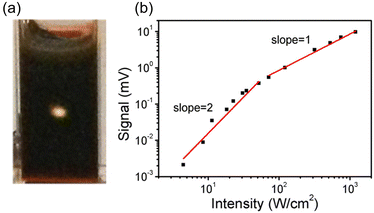 | ||
| Fig. 5 (a) UC fluorescence from PbSe/rubrene excited at 980 nm CW laser and (b) excitation intensity dependency of UC intensity form PbSe/rubrene. Reproduced from ref. 35 with permission from American Chemical Society, Copyright 2015. | ||
In the alternative strategy (B), as depicted in Scheme 2, the formed excited triplet state moves from a sensitizer to a transmitter ligand through TET1, and subsequently, through TET2 from the transmitter ligand to the emitter, enhancing the 3Em*. Tang and colleagues synthesized nano-complex sensitizers (CdSe:9-ACA) by replacing the octadecylphosphonic acid ligands (ODPA) on the surfaces of 3.3 nm CdSe nanoparticles with 9-anthracene carboxylic acid (9-ACA). These sensitizers were then combined with the emitter, DPA. In this approach, the triplet energy generated in CdSe nanoparticles efficiently forms the T1 state of DPA, mediated by 9-ACA as the triplet energy transmitter. Notably, in the simple mixed system of CdSe nanoparticles and DPA (CdSe/DPA; Scheme 2), no blue UC emission was observed from DPA under green excitation light at 532 nm, possibly owing to the small Bohr radius of CdSe nanoparticles (4–5 nm). For the CdSe:9-ACA/DPA system, blue UC emission was observed from green excitation light (532 nm) with ΦUC = 4.5%  (Fig. 6(a) and (b)).35 Subsequent detailed experiments by the same group on the CdSe:9-ACA/DPA system using Strategy B revealed that the UC efficiency is higher when there are more 9-ACA transmitters on the surfaces of CdSe nanoparticles. Additionally, they found a direct correlation between
  and the nanoparticle's photoluminescence quantum yield ΦPL and an indirect correlation with nanoparticle size.37 Then, they performed time-resolved photoluminescence spectroscopy and determined that the energy transfer rate constant (kTET1) from CdSe nanoparticles to 9-ACA transmitters is 1.5 × 10⁷ s−1.38
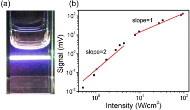 | ||
| Fig. 6 (a) UC fluorescence from CdSe:9-ACA/DPA excited at 532 nm CW laser and (b) excitation intensity dependency of UC intensity form CdSe:9-ACA/DPA. Reproduced from ref. 35 with permission from American Chemical Society, Copyright 2015. | ||
In addition to introducing carboxylic acid at the 9-position of anthracene, carboxylic acid can also be introduced at the 1- and 2-positions. Furthermore, not only carboxylic acid derivatives of anthracene but also three isomers of dithiocarbamate (ADTC) derivatives of anthracene (1-ADTC, 2-ADTC, 9-ADTC) can be used as transmitters in TTA-UC. For TTA-UC in solution systems (CdSe:Trans/DPA, Trans = 1-ACA, 2-ACA, 9-ACA and 1-ADTC, 2-ADTC, 9-ADTC) consisting of CdSe nanoparticles and complexes with these ACA or ADTC transmitters along with DPA, the highest efficiency was obtained using 9-ACA, with ΦUC = 6%  , and the lowest efficiency was observed using 9-ADTC, with ΦUC = 0.05%
  . Using 1-ACA and 1-ADTC resulted in a ΦUC of 1.5%
  , and using 2-ACA and 2-ADTC yielded a ΦUC of 0.5%
  . This suggests that in TET based on Dexter-type energy transfer, the overlap of orbitals between the triplet energy donor and acceptor is crucial (eqn (7)), and the orientation of the transmitter with respect to the nanoparticle sensitively affects the efficiency of TET1.39
The group led by Yanai, Kimizuka, Teranishi, and Sakamoto systematically evaluated TET1 and TTA-UC in systems where perylene-3-carboxylic acid (Pe) was complexed as a transmitter ligand on the surfaces of CdX nanoparticles (X = Se, Te), namely CdX:Pe, and in CdX:Pe/tBu4P systems (tBu4P = 2,5,8,11-tetra-tert-butylperylene). They systematically varied the chalcogen X, nanoparticle size, and number of Pe ligands. The efficiency of TET1 depended on the triplet exciton energy of the nanoparticles, with smaller nanoparticles (larger bandgap) showing improved TET1 efficiency. However, reducing the size led to a decrease in surface area, suppressing the coordination number of Pe. They emphasized the importance of optimizing this balance to achieve high TET1 efficiency.40
Detailed research has been conducted on the kinetics of TET1 between semiconductor nanoparticles and transmitter ligands. Generally, the rate constant for Dexter-type energy transfer in TET is exponentially reduced with the distance (d) between the triplet donor and acceptor, as expressed in the following equation:41
kTET = k0![[thin space (1/6-em)]](https://www.rsc.org/images/entities/char_2009.gif) exp(−βd) exp(−βd) | (10) |
 .41
.41
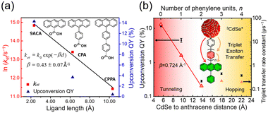 | ||
| Fig. 7 Distance dependence of the TET rate constant and UC efficiency in (a) CdSe:X/DPA (X = 9-ACA, CPPA, CP4A) and (b) CdSe:PyPxPAn/DPA (x = 0–4) systems. Reproduced from ref. 41 with permission from Journal of American Chemical Society, Copyright 2016 and ref. 42 with permission from American Chemical Society, Copyright 2020. | ||
Furthermore, a transmitter, namely PyPxPAn (x = 0–4; 4-(10-phenylanthracen-9-yl)pyridine (PyP0PAn), 4-(4-(10-phenylanthracen-9-yl)phenyl)pyridine (PyP1PAn), 4-(2,5-bis(2-ethylhexyl)-4′-(10-phenylanthracen-9-yl)-[1,1′-biphenyl]-4-yl)pyridine (PyP2PAn), 4-(2′,5′-bis(2-ethylhexyl)-4′′-(10-phenylanthracen-9-yl)-[1,1′:4′,1′′-terphenyl]-4-yl)pyridine (PyP3PAn), 4-(2′,5′-bis(2-ethylhexyl)-4′′′-(10-phenylanthracen-9-yl)-[1,1′:4′,1′′:4′′,1′′′-quaterphenyl]-4yl)pyridine (PyP4PAn)), was developed by the same group, where the distance between 10-phenylanthracene (PAn) and pyridine (Py) was controlled by the number of phenylene units x (Fig. 7(b)). For the CdSe:PyPxPAn/DPA system, where CdSe nanoparticles were complexed with PyPxPAn and mixed with DPA, the ΦUC decreased as the number of phenylene units x increased from 0 to 2 ( (x = 0), 2.26% (x = 1), 0.142% (x = 2) (
 (x = 0), 4.51% (x = 1), 0.284% (x = 2)). However, an increasing trend in ΦUC was observed for x = 3 and 4 (
 (x = 3), 0.206% (x = 4) (
 (x = 3), 0.413% (x = 4)). Up to x = 2, Dexter-type TET1 from CdSe to PAn occurred with the attenuation factor β = 0.724 Å−1. However, reaching x = 3 and 4, a transition from exciton tunneling to hopping effects occurred, leading to TET1 that did not depend on distances, beyond the conventional Dexter distance (∼1 nm).42
Additionally, molecules capable of bidentate coordination have been employed as transmitters. For instance, isomers of bis(pyridine)anthracene, such as 2-(10-(pyridin-3-yl)anthracen-9-yl)pyridine (2,3-PyAn), 9,10-di(pyridin-3-yl)anthracene (3,3-PyAn), and 9,10-di(pyridin-2-yl)anthracene (2,2-PyAn), were complexed with CdSe nanoparticles and evaluated in solution systems with DPA. It was revealed that (1) TET1 from CdSe to the transmitter is correlated with UC efficiency, and (2) there is a tendency for  to be higher in the order of 2,2-PyAn < 3,3-PyAn < 2,3-PyAn.43 Furthermore, phosphoric acid-based transmitters, such as 10-phenylanthracene-1,8-diyl bis(dihydrogen phosphate) (10-Ph-ADP) with phosphoric acid anchors introduced at the 1,8-positions of anthracene, have been developed. For the system where CdSe and 10-Ph-ADP are complexed (CdSe:10-Ph-ADP) and mixed with DPA in solution, a ΦUC of 8.5%
  was recorded, demonstrating higher performance compared with CdSe:9-ACA/DPA (ΦUC = 6.5%;
  ). Transient absorption spectroscopy revealed that the 10-Ph-ADP transmitter has a lifetime characteristic of the T1 state that is 3.4 times longer than that of 9-ACA.44
Transmitters with extended conjugation in the acene series have been developed to lower the T1 energy of the transmitter, achieving an efficient energy cascade. Tang and colleagues synthesized PbX:CPT (X = S or Se) nanostructures, where tetracene-based 4-(tetracene-5-yl)benzoic acid (CPT) transmitters with slightly higher T1 energy than rubrene were complexed on the surfaces of CdX (X = S or Se) nanoparticles (Fig. 8(a)). They successfully achieved an efficient TET cascade from these PbX:CPT sensitizers to rubrene, converting NIR excitation light (808 nm) into yellow emission with a ΦUC of ∼1% ( of ∼2%).45 Additionally, using highly pure lead and thiourea precursors, PbS nanoparticles were synthesized and complexed with 5-carboxylic acid tetracene (5-CT) transmitters, resulting in the sensitizer PbS:5-CT. In a mixture system of PbS:5-CT/rubrene, this sensitizer efficiently upconverted 781 nm NIR excitation light to 560 nm yellow emission with ΦUC = 5.9%
  (Fig. 8(b)). The high UC performance is attributed to (1) improved crystallinity leading to longer lifetimes of PbS excitons and (2) the long lifetime of the T1 state in the 5-CT transmitter.46
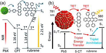 | ||
| Fig. 8 (a) TTA-UC scheme for the PbX:CPT/rubrene system. Reproduced from ref. 45 with permission from Royal Society of Chemistry, Copyright 2016. (b) TTA-UC scheme for the PbS:5-CT/rubrene system. Reproduced from ref. 46 with permission from American Chemical Society, Copyright 2019. | ||
Among acene-based transmitters, the pentacene derivative 4-(6,13-bis(2-(triisopropylsilyl)ethynyl)pentacen-2-yl)benzoic acid (2-CP) has the longest conjugation (Fig. 9). The sensitizer PbS:2-CP, using PbS nanoparticles with a diameter of 3.3 nm, were complexed with 2-CP, and the energy transfer from PbS to the transmitter was studied in detail. Transient absorption spectroscopy and density functional theory (DFT) calculations revealed that PbS:2-CP forms a charge carrier intermediate localized on the nanoparticle surface within 40 ps of photo-excitation and subsequently forms the T1 state of 2-CP over 100 ns.47 The 2-CP transmitter and similar compounds have been used as molecules that achieve efficient singlet fission in several instances.48,49
 | ||
| Fig. 9 PbS:2-CP and its TET scheme. Reproduced from ref. 47 with permission from American Chemical Society, Copyright 2018. | ||
Evangelista, Egap, and Lian's group evaluated the performance of TET1 in a complex (CdSe:T6) where oligothiophene carboxylic derivative 3′′′,4′′-dihexyl-[2,2′:5′,2′′:5′′,2′′′:5′′′,2′′′′:5′′′′′,2′′′′′-sexithiophene]-5-carboxylic acid (T6) was coordinated as a transmitter on the surfaces of oleic acid-protected CdSe nanoparticles. According to transient absorption spectroscopy results, in a 1![[thin space (1/6-em)]](https://www.rsc.org/images/entities/char_2009.gif) :
:![[thin space (1/6-em)]](https://www.rsc.org/images/entities/char_2009.gif) 1 complex of CdSe and T6, kTET1 from CdSe to T6 was determined to be 0.077 ns−1. Unlike previously reported acene-based transmitters, thiophene-based transmitters offer high stability and flexible molecular design, supporting further progress in this field.50
1 complex of CdSe and T6, kTET1 from CdSe to T6 was determined to be 0.077 ns−1. Unlike previously reported acene-based transmitters, thiophene-based transmitters offer high stability and flexible molecular design, supporting further progress in this field.50
Designing an energy cascade for the entire TTA-UC system through the transmitter ligand is crucial for achieving efficient TTA-UC. However, multi-step energy transfer can lead to energy losses. Rao and colleagues addressed this challenge by finding a way to minimize energy losses (Fig. 10). They demonstrated that 1) 5,11-bis(triethylsilylethynyl)anthradithiophene (TES-ADT) binds to PbS nanoparticles and rapidly extracts triplet energy from the excited state of PbS (kTET1 ∼ 2 × 10⁸ s−1), and 2) the triplet-sensitized 3(TES-ADT)* also acts as an annihilator in TTA-UC. By leveraging these behaviors, they successfully upconverted 1064 nm NIR excitation light to 610 nm visible light in the PbS:TES-ADT/TES-ADT system (ΔEAS = 0.86 eV, ΦUC = 0.047%, Ith = 43 W cm−2). The use of the TES-ADT, serving as both a transmitter and emitter, helps achieve relatively high ΦTET (8.8 ± 0.8% in a 50 mM TES-ADT solution), even with a relatively small TET driving force between PbS sensitizer and TES-ADT, enabling high-efficiency TET that was not possible with conventional annihilators.51
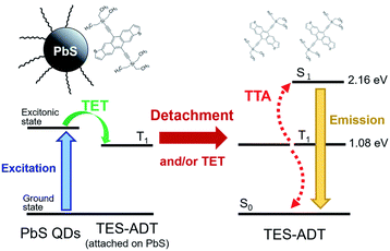 | ||
| Fig. 10 TTA-UC scheme for PbS:TES-ADT/TES-ADT. Reproduced from ref. 51 with permission from Royal Society of Chemistry, Copyright 2019. | ||
Deployment of nanoparticle sensitizers and emitters into solid-state devices has also been achieved. Baldo and colleagues developed a solid-state device by dispersing a monolayer of CdS nanoparticles on a glass substrate and casting a film of rubrene crystal containing red-emitting dibenzotetraphenylperiflanthene (DBP) on top. In this case, the rubrene crystal acts as both the annihilator for triplet excitons and the diffusion field for singlet excitons. UC occurs through energy transfer from singlet excitons in the rubrene crystal to DBP. Using three CdS nanoparticles of different sizes to control the absorption wavelength, the estimated ΦUC and Ith ranged from 1.2% to 0.21% and 12 to 26 mW cm−2 for 808 nm excitation, respectively. This study further demonstrated the conversion of NIR excitation light with a wavelength exceeding 1 μm (using an absorption intensity less than one sun) to red emission at 612 nm.52 Very recently, solid-state UC materials combining PbS nanoparticles as sensitizers, TES-ADT as transmitter/annihilator, and DBP dye have also been developed.53
Core–shell nanoparticles
The main advantage of nanoparticles is the modulation of their electronic structure with small changes in their size and structure. Core–shell nanoparticles with distinct compositions in the interior and on the surface have several beneficial properties in the context of TTA-UC.As an example, we describe the TTA-UC characteristics of PbS@CdS core–shell nanoparticles in a rubrene solution (PdS@CdS/rubrene), as reported by Tang and coworkers.54 In such systems, increasing the thickness of the CdS shell while maintaining the nanoparticle size leads to an increase in  (Fig. 11(a)). This phenomenon is attributed to the CdS shell suppressing nonradiative recombination by passivating trap states and the enhanced efficiency of TET due to the increase in bandgap (Eg) with decreasing core size. Further thickening of the shell results in a decrease in
  . In these particles, the CdS shell functions as an insulating layer (β = 3.4 Å−1, eqn (10)), inhibiting the wavefunction overlap between the PbS core and rubrene, thus explaining this behavior (Fig. 11(b)). For the PdS@CdS with the highest ΦUC, a solution system containing tetracene-based 5-CT transmitter and rubrene (PdS@CdS:5-CP/rubrene; Fig. 11(c)) resulted in a ΦUC of 4.2%
  . This ΦUC is approximately 37 times higher compared with the solution system without a transmitter (PdS@CdS/rubrene). Additionally, PdS@CdS:5-CP/rubrene exhibits an extremely low Ith of 3.2 mW cm−2 (Fig. 11(d)).54 Moreover, in systems where PbS nanoparticles are complexed with a tetracene-based transmitter (5-CT) (PbS:5-CT/rubrene), covering the PbS core with a CdS shell (PbS@CdS:5-CT/rubrene) suppresses hole transfer from the PbS core to 5-CT, enhancing ΦTET and ΦUC.55 Additionally, Zn and Cd adsorption on the surfaces of PbS nanoparticles induces defect levels, enhancing TTA-UC efficiency by up to 700-fold and 325-fold, respectively, compared with pristine PbS.56 2,5-diphenyloxazole (PPO) possesses properties of both an emitter and a transmitter. In the solution system using CdS@ZnS core–shell nanoparticles and PPO (CdS@ZnS:PPO/PPO), a maximum ΦUC of 2.6%
  has been reported, achieving UC of 405 nm blue excitation light to 355 nm UV light.57
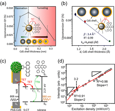 | ||
| Fig. 11 (a) ΦUC in the PbS@CdS/rubrene system when the particle size was constant and the CdS shell thickness was changed. (b) ΦUC in the PbS@CdS/rubrene system when the core PbS size was constant and the CdS shell thickness was changed. (c) TTA-UC mechanism in the PbS@CdS:5-CT/rubrene system. (d) Log–log plot of UC intensity versus excitation intensity in the PbS@CdS:5-CT/rubrene system. Reproduced from ref. 54 with permission from American Chemical Society, Copyright 2016. | ||
Perovskite nanocrystals
Perovskite-type CsPbX3 (X = halogen) nanocrystals are capable of altering excitonic properties by changing the halogen type. Owing to their small exciton binding energy and high absorption cross-section, these nanocrystals are suitable for light-harvesting in solar cells.Yanai and Kimizuka et al. developed a sensitizer (CsPbX3:DPAEA) by partially replacing the oleylamine surface-protecting ligands of CsPbX3, (X = Br/I) nanocrystals with an amine derivative of DPA, 4-(10-phenyl-9-anthracenyl)benzeneethanamine (referred to as DPAEA in this manuscript) (Fig. 12(a)). The evaluation of the photoluminescence lifetimes for the CsPb(Br/I)3 and CsPb(Br/I)3:DPAEA sensitizer indicated a ΦTET1 of 0.38 from CsPbX3 to the DPAEA transmitter. In the solution system composed of CsPb(Br/I)3:DPAEA and DPA emitter (CsPb(Br/I)3:DPAEA/DPA), UC from 532 nm to 434 nm was observed, with ΦUC = 0.65%  and Ith = 25 mW cm−2 (Fig. 12(b)–(d)).58 Subsequently, the same group achieved TTA-UC from visible light to UV light in another system. They successfully developed a sensitizer (CsPbX3:NCA) by coordinating a naphthalene-based 1-naphthoic acid (NCA) transmitter on the surfaces of CsPbX3 nanocrystals with different halogens (X = Cl/Br). The ΦTET1 from CsPb(Cl/Br)3 to NCA was estimated to be 0.32, and by mixing CsPb(Cl/Br)3:NCA with PPO emitter, they achieved the UC of 445 nm visible excitation light to 363 nm UV light (ΔEAS = 0.63 eV, ΦUC = 2.6%
  , Ith = 4.7 W cm−2).59 Furthermore, the group introduced 4-(2-phenyloxazol-5-yl)benzenesulfonate (PPOS) as a transmitter ligand on the surfaces of CsPbBr3 nanocrystals and combined it with a naphthalene derivative emitter 1,4-bis((triisopropylsilyl)ethynyl)naphthalene (TIPS-Nph). This combination achieved TTA-UC from 515 nm green excitation light to 375 nm UV light (ΔEAS = 0.90 eV, ΦUC = 0.007%
  , Iex = 16 W cm−2).60
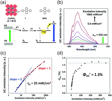 | ||
Fig. 12 (a) Scheme of TTA-UC for CsPb(Br/I)3:DPAEA/DPA. (b) UC spectra of free DPA measured at various excitation intensities using a 532 nm laser. (c) Excitation intensity dependence of UC intensity at 430 nm for CsPb(Br/I)3:DPAEA/DPA. (d) Excitation intensity dependence of  . Reproduced from ref. 58 with permission from Royal Society of Chemistry, Copyright 2017. . Reproduced from ref. 58 with permission from Royal Society of Chemistry, Copyright 2017. | ||
Xu and coworkers developed a sensitizer that is a complex of CsPbBr3 nanocrystals and 1-pyrenecarboxylic acid (PCA) as transmitter. This composite recorded a ΦUC of 0.85% when mixed with DPA, while Ce–CsPbBr3, in which CsPbBr3 nanocrystals were doped with cerium (Ce), was found to improve the ΦUC to 2.40%. Interestingly, the efficiency of TET1 varies with the amount of Ce doping, indicating that doping can tune the electronic structure for suitable TTA-UC.61
Metal-free nanoparticles
In the aforementioned inorganic nanoparticle sensitizers, heavy metal elements, such as Cd and Pb, are used. However, such inorganic nanoparticles exhibit weak electronic coupling with organic transmitter molecules on their surfaces. As a result, the carrier wave functions excited in the nanoparticles tend to be localized either within the internal regions or on the surfaces of the nanoparticles.In recent studies by Tang and colleagues, nanoparticles made of silicon, in addition to semiconductor nanoparticles, have been employed as sensitizers. Silicon is an abundant element on Earth, and because of its low toxicity, it has gained attention as a clean material. Silicon nanoparticles are expected to have a very small gap (∼10 meV) between bright exciton states and dark triplet states, allowing for efficient triplet generation.62
Tang and colleagues synthesized Si:9EA or Si:3EP nanoparticle complexes by reacting 9-vinylanthracene or 3-vinylperylene with silicon nanoparticles protected by alkane, resulting in the binding of 9-ethylanthracene (9EA) or 3-ethylperylen (3EP) to the surfaces of silicon nanoparticles with a diameter of ∼3 nm (Fig. 13).63,64 In the solution system composed of Si:9EA and DPA (Si:9EA/DPA), UC from 488–640 nm excitation light to 425 nm fluorescence was achieved with a maximum ΦUC of 3.5%  .65 The Ith was estimated to be 0.95 W cm−2 for 488 nm excitation and 2 W cm−2 for 532 nm excitation, and this difference in Ith is attributed to the larger absorption cross-section of silicon nanoparticles in the short-wavelength region (eqn (9)).65 When the size of silicon nanoparticles decreased from 3.6 to 3.1 nm, ΦUC increased from 0 to 3.5 ± 0.5%
  . This occurs because the bandgap increases as the nanoparticle size decreases. When the bandgap exceeds the T1 energy of 9EA (1.8 eV), efficient TET1 is observed. Further analysis revealed that the triplet excitons generated in silicon nanoparticles undergo Dexter-type TET (ΦTET1 = 0.48) to 9EA in approximately 15 ns. Other factors contributing to losses in the TET1 process include the presence of silicon nanoparticles without bound 9EA, the existence of silicon nanoparticles with an excessively small Eg (larger size), and the degradation of silicon nanoparticles. Overcoming these non-uniformity and instability issues may enable TET up to 91% in silicon nanoparticles.65
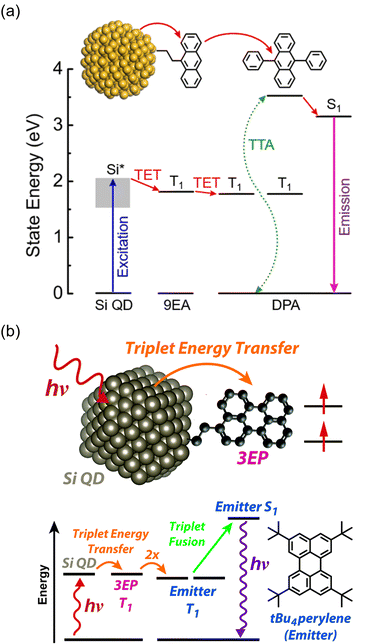 | ||
| Fig. 13 (a) Schematic illustration of Si:9EA/DPA and its TTA-UC scheme. Reproduced from ref. 63, with permission from Royal Society of Chemistry, Copyright 2022 (b) Schematic illustration of Si:3EP/tBu4P and its TTA-UC scheme. Reproduced from ref. 64 with permission from Royal Society of Chemistry, Copyright 2021. | ||
The same research group has recently adopted a novel approach to enhance TET efficiency.66 Specifically, they modified the binding mode of the anthracene-derived transmitter on the surfaces of silicon nanoparticles from C–C single bonds (Si:9EA) to C![[double bond, length as m-dash]](https://www.rsc.org/images/entities/char_e001.gif) C double bonds (Si:9VA, 9VA = 9-vinylanthracene). This alteration allowed carriers formed in the silicon nanoparticles to delocalize across both the anthracene and silicon nanoparticles, establishing a strongly electronically coupled composite nanosystem. These observations are supported by DFT calculations, indicating that (1) the band-decomposed partial charge density of Si:9VA is significantly broader compared with that of Si:9EA, and (2) the Si:9VA system exhibits a stronger electronic coupling between the anthracene moiety of the transmitter and the silicon nanoparticle, leading to a lower triplet energy compared with that of Si:9EA. In Si:9VA, transient absorption spectroscopy revealed that a new band of triplet states with both characteristics is formed because of the strong electronic coupling between silicon nanoparticles and 9VA. This results in the enhancement of ISC from the singlet excitons localized on the silicon nanoparticles to the newly formed triplet exciton states on a timescale of approximately 3 ns. This suggests that triplet band of Si:9VA can be tuned by adjusting the coordination number of 9VA, emphasizing the effectiveness of optimizing the coordination number, to obtain efficient triplet sensitization of the desired emitter. When combining the Si:9VA sensitizer that has an optimized average coordination number of 1.8 with a DPA emitter in a solution system (Si:9VA/DPA), a high ΦUC of 1.8%
C double bonds (Si:9VA, 9VA = 9-vinylanthracene). This alteration allowed carriers formed in the silicon nanoparticles to delocalize across both the anthracene and silicon nanoparticles, establishing a strongly electronically coupled composite nanosystem. These observations are supported by DFT calculations, indicating that (1) the band-decomposed partial charge density of Si:9VA is significantly broader compared with that of Si:9EA, and (2) the Si:9VA system exhibits a stronger electronic coupling between the anthracene moiety of the transmitter and the silicon nanoparticle, leading to a lower triplet energy compared with that of Si:9EA. In Si:9VA, transient absorption spectroscopy revealed that a new band of triplet states with both characteristics is formed because of the strong electronic coupling between silicon nanoparticles and 9VA. This results in the enhancement of ISC from the singlet excitons localized on the silicon nanoparticles to the newly formed triplet exciton states on a timescale of approximately 3 ns. This suggests that triplet band of Si:9VA can be tuned by adjusting the coordination number of 9VA, emphasizing the effectiveness of optimizing the coordination number, to obtain efficient triplet sensitization of the desired emitter. When combining the Si:9VA sensitizer that has an optimized average coordination number of 1.8 with a DPA emitter in a solution system (Si:9VA/DPA), a high ΦUC of 1.8%  was achieved. Furthermore, for Si:9VA with an average coordination number of 2.9, when combined with a tBu4P emitter, an inner filter effect was considered, resulting in a UC efficiency of 8.6% (17.2% (100% maximum)) and an Ith of 0.5 W cm−2.66
4. Inorganic nanocluster sensitizers
Nanoclusters are composed of a few to several dozen atoms, making them smaller than nanoparticles, and have been studied since the early 1980s, primarily obtained through vacuum-based gas-phase experiments.67,68 Notably, fullerene, known for a ΦISC of ∼100%, is a carbon nanocluster. In the late 1990s, stable handling of metal nanoclusters under atmospheric conditions became feasible by protecting them with ligands, and in the 2000s, various precise synthetic methods were established in liquid phases. The molecular structures of ligand-protected metal nanoclusters composed of noble metals such as gold, silver, and platinum have been revealed through single-crystal X-ray structural analysis, with numerous reported examples.69–72 Thus, ligand-protected metal nanoclusters represent well-structured and defined systems that enable precise control of size and composition. Furthermore, scaling laws do not apply to these substances, and even a one-atom difference in composition significantly influences their structure and properties.73Mitsui and colleagues discovered that ligand-protected metal nanoclusters can sensitize the triplet states of fluorescent dyes, leading to the exploration of metal nanoclusters in TTA-UC studies. The first observation of triplet sensitization occurred in a mixed system of thiolate-protected silver and platinum-containing MAg24 nanoclusters ([PPh4]n[MAg24(DMBT)18], (M, n) = (Ag, 1), (Pt, 2)) with perylene and TIPS-anthracene (TIPS-Ac) (PPh4 = tetraphenylphosphonium ion, DMBT = 2,4-dimethylbenzenethiolate), reported in 2020.74 Both Ag25 and PtAg24 exhibit a structure where a central M atom is surrounded by an icosahedral Ag12 core covered by six [Ag2(DMBT)3] oligomers (Fig. 14(a)).72,75 When these MAg24 nanoclusters were mixed with fluorescent dyes and excited with 640 nm light under deoxygenated conditions, UC emission was observed for both solution samples. The TET efficiency of PtAg24/emitter (KSV ∼300 M−1, kTET ∼2 × 10⁸ s−1) was significantly higher than that of Ag25/emitter (KSV ∼16 M−1, kTET ∼1.5 × 10⁷ s−1), attributed to the lower absorption energy in Ag25, resulting in a smaller driving force for TET. Blue UC photon was observed in the mixed solution of MAg24/emitter under deoxygenated conditions upon 640 nm excitation, and the quantum yield (ΦUC ∼1%) of PtAg24/emitter was orders of magnitude higher than that of Ag25/emitter (ΦUC ∼10−4%) (Fig. 14(b) and (c)). However, the reason for this discrepancy could not be solely explained by TET efficiency. Therefore, the authors undertook an analysis of the triplet generation efficiency of metal nanoclusters, which was previously unclear, by considering the loss processes in UC (self-absorption and sensitizer-induced deactivation of 3Em*), in a TTA-UC framework.19 As a result, the triplet generation efficiency of PtAg24 was found to be approximately 230 times larger than that of Ag25. For such thiolate-protected metal nanoclusters, a model has been proposed, suggesting that the core is responsible for light absorption, with the excited energy rapidly moving to the surface, where the oligomers emit light (Fig. 14(d)).76,77 The authors interpreted the triplet generation efficiency obtained from TTA-UC analysis as the efficiency of surface triplet excitations, proposing a deactivation model for MAg24. Consequently, the luminescence was attributed to phosphorescence from the surface. Moreover, by optimizing the system, the team achieved UC from 785 nm NIR light to blue light with a ΔEAS exceeding 1 eV in both the solution and solid states, marking the first example of exciting the T1 state of perylene with 785 nm NIR light.74
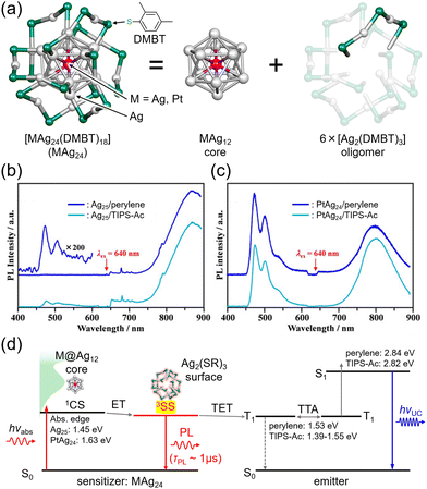 | ||
| Fig. 14 (a) Schematic illustration of MAg24 (M = Ag, Pt). (b) and (c) Photoluminescence spectra for deaerated solution of Ag25/emitter and PtAg24/emitter (emitter = perylene or TIPS-Ac), respectively, excited by 640 nm. (d) Relaxation process of excited MAg24 and energy diagram of TTA-UC in the MAg24/emitter system. Reproduced from ref. 74 with permission from Wiley-VCH GmbH, Copyright 2020. | ||
Other cluster with icosahedral Ag12 cores doped with Pt, [Ag28Pt(BDT)12(PPh4)4]4−, has also been reported by Bakr et al. This cluster has a PtAg12 core protected by Ag16(BDT)12 ligand shell composed of Ag and dithiolate (1,3-benzenedithiolate) and PPh3.78 Mitsui et al. evaluated the excited state and TTA-UC properties of a PtAg28 cluster ([PtAg28(BDT)12]4−) without the secondary ligand, PPh3. Quantum chemical calculations showed that the electron configuration of S1 and T1 in PtAg28 is similar, which results in a smaller matrix element of the spin–orbit coupling between S1 and T1, slowing down these ISCs. On the other hand, there is a T2 level capable of direct SOC at energies lower than S1, and a highly efficient T1 state is formed by the S1 → T2 → T1 pathway (ΦISC ∼ 1). The resulting T1 state has charge transfer properties from the PtAg12 core to the surface, giving it excellent sensitization ability; PtAg28, in combination with DPA, achieves TTA-UC from 532 nm excitation light to blue (ΔEAS = 0.52 eV) with a ΦUCg of 12.2% and its Ith recorded an extremely low value of 0.81 mW cm−2.79
The icosahedral 13-atom metal core is commonly observed in ligand-protected metal nanoclusters, not limited to MAg24 mentioned earlier.80 Among them, the Au13 nanocluster protected by diphosphine and halogen, [Au13(dppe)5Cl2]3+ (dppe = 1,2-bis(diphenylphosphino)ethane), stands out as one of the most well-known gold nanoclusters (Fig. 15(a)).81–86 Because the molecular orbitals of such ligand-protected metal nanoclusters have analogous shapes to atomic orbitals (s, p, d,…), they are often referred to as “superatoms,” and their molecular orbitals are termed “superatomic orbitals” (S, P, D,…). In recent years, it has been demonstrated that the Au13 nanocluster in the Au13/perylene solution system undergoes TTA-UC from red (640 nm) to blue (472 nm), revealing the ability of the Au13 nanocluster to sensitize the T1 state of perylene (Fig. 15(b)–(d)).87 Furthermore, the mechanism of triplet state generation in these Au13 nanoclusters has been elucidated through the understanding of superatomic orbitals.88
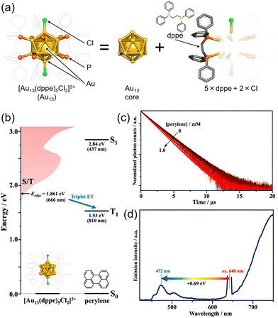 | ||
| Fig. 15 (a) Schematic illustration of Au13. (b) Energy-level diagram of Au13 and perylene. (b) Photoluminescence decay curves of Au13 in deaerated solvent using 634 nm excitation. (c) Photoluminescence spectrum obtained for the deaerated solution of Au13/perylene using 640 nm CW laser excitation. Reproduced from ref. 85 with permission from American Chemical Society, Copyright 2022. | ||
The rod-shaped nanocluster rod-Au25, first reported by Tsukuda et al., has a shared gold atom from two icosahedral Au13. One of these rod-Au25 clusters, [Au25(PPh3)10(PET)5Cl2](SbF6)2 (PPh3 = triphenylphosphine, PET = 2-phenylethanethiolate, SbF6 = hexafluoroantimonate ion) (Fig. 16(a)),89–92 also exhibits TTA-UC characteristics when combined with BPEA (9,10-bis(phenylethynyl)anthracene) or rubrene (Fig. 16(b)–(d)). Owing to its longer-wavelength absorption compared with Au13, rod-Au25 is anticipated to display NIR TTA-UC.93 Furthermore, rod-Au25 nanoclusters have an ΦISC of nearly 1, making them suitable as phosphorescent materials with a dark S1 state and bright T1 state at room temperature. Similar to other ligand-protected metal nanoclusters, the electronic structure of rod-Au25 can be modified by substituting different metal atoms.94–105 Alloyed rod-Au25−xAgx exhibits unique properties; for 0 ≤ x ≤ 12, the photoluminescence quantum yield is low, but at x = 13, there is a sudden and significant increase, approximately 200-fold.106 Mitsui and colleagues conducted TTA-UC analysis of rod-Au25−xAgx/perylene, revealing the following key findings: (1) photoluminescence from Au25−xAgx is phosphorescent, (2) x = 12 may have the same high photoluminescence quantum yield as x = 13, and (3) substituting Ag atoms in the connecting part of the icosahedral core results in a higher energy shift of the triplet energy and enhancement of phosphorescence.107
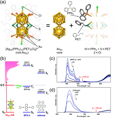 | ||
| Fig. 16 (a) Schematic illustration of rod-Au25. (b) Energy-level diagram of the Au25, BPEA and rubrene. (c) Photoluminescence spectra obtained for the deaerated solution of Au25/BPEA using 640 nm excitation. (d) Photoluminescence spectra obtained for the deaerated solution of rod-Au25/rubrene using 785 nm excitation. Reproduced from ref. 93 with permission from Royal Society of Chemistry, Copyright 2022. | ||
The Au2Cu6 nanocluster reported by Zhu and colleagues, [Au2Cu6(S-Adm)6(PPh3)2] (S-Adm = 1-adamantanethiolate) (Fig. 17(a) and (c)), features a highly symmetric structure, with a cyclic copper-thiolate oligomer [Cu-S(-Adm)-]6 surrounding an upper and lower PPh3-coordinated Au2 dimer.108,109 Mitsui and coworkers discovered that this Au2Cu6 nanocluster exhibits the rare ability to simultaneously emit both fluorescence and phosphorescence. Using platinum(II) octaethylporphine (PtOEP) and perylene in solution (PtOEP/perylene) as a reference system, they estimated the ΦISC of Au2Cu6 to be 0.47.110 Additionally, detailed excitation relaxation processes of Au2Cu6 nanoclusters were revealed by temperature-dependent luminescence spectroscopy, marking the first instance of detailed experimental insight into the excitation relaxation processes of metal nanoclusters.110
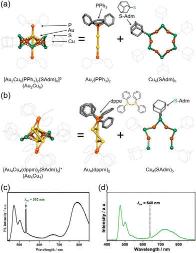 | ||
| Fig. 17 (a) Schematic illustration of Au2Cu6. (b) Schematic illustration of Au4Cu4. (c) Photoluminescence spectrum obtained for the deaerated solution of Au2Cu6/perylene with the 532 nm CW laser excitation. Reproduced from ref. 110 with permission from Royal Society of Chemistry, Copyright 2022. (d) Photoluminescence spectrum obtained for the deaerated solution of Au4Cu4/perylene with the 640 nm CW laser excitation. Reproduced from ref. 112 with permission from American Chemical Society, Copyright 2023. | ||
The research group also conducted TTA-UC analysis for an Au4Cu4 nanocluster, [Au4Cu4(dppm)2(S-Adm)5]Cl (dppm = 1,1-bis(diphenylphosphino)methane) (Fig. 17(b) and (d)),111 elucidating the detailed excited states of this nanocluster.112 Although Au4Cu4 and Au2Cu6 exhibit similar absorption spectra, fluorescence was not observed in Au4Cu4. TTA-UC analysis was performed using 640 nm excitation light with perylene or DPA, and ΦISC for Au4Cu4 was estimated to be 0.97. Upon estimating the activation barrier between S1 and T1, the activation barrier for Au4Cu4 was determined to be 4.8 meV, significantly lower compared to that for Au2Cu6 (250 meV). Analysis of excited states through DFT calculations for both singlet and triplet state of Au4Cu4 revealed the presence of isoenergetically isomers with slightly different ring structures formed by four Au atoms. Since the matrix elements for ISC between the same isomers are zero, ISC processes without structural changes are less favorable, whereas ISC accompanied by flexible structural changes between isomers is feasible. The ISC rate constant in this model was estimated by employing Marcus semiclassical electron transfer theory, which closely reproduced the experimental values. Therefore, the authors propose that the flexibility in such structural arrangements of Au4Cu4 enhances ISC. Au4Cu4 exhibits a longer photoluminescence lifetime compared with Au2Cu6, and its ΦUC is remarkably high at 14%  , with a low threshold intensity (Ith = 26 mW cm−2), demonstrating its efficiency as a UC material.112
As described above, many ligand-protected metal nanoclusters can function as sensitizers for the triplet states of fluorescent dyes, and these nanoclusters are being recognized as potential sensitizers for TTA-UC, similar to inorganic nanoparticles. However, the electronic states related to the luminescence of ligand-protected metal nanoclusters have not been fully elucidated. For example, the radiative lifetimes are calculated to be in the range of tens to hundreds of microseconds. This uncertainty, along with other factors, contributes to the lack of fundamental knowledge, making it difficult to determine whether the luminescence of nanoclusters is fluorescence or phosphorescence.
Notably, TTA-UC analysis provides optical and photophysical insights related to the excited states of these metal nanoclusters. This aspect is of great interest, both industrially and academically, because it helps clarify the fundamental nature of nanocluster luminescence.
5. Conclusions and perspectives
This review focuses on the recent research in TTA-UC, with an emphasis on studies using inorganic nanomaterials, such as semiconductor nanoparticles, nanocrystals, and ligand-protected metal nanoclusters, as triplet sensitizers, and introduces the concepts of triplet sensitization, TTA-UC characteristics, and the insights derived from these studies.The physical properties of inorganic nanoparticles and nanocrystals follow scaling law based on particle size, allowing for a reasonable prediction of electronic structure from particle size. Their stability, simplicity of synthesis, and potential for large-scale industrial production make them promising sensitizers. In TTA-UC with inorganic nanoparticles, changes in the bandgap associated with variations in particle size significantly affect the TET efficiency. The development of efficient transmitter ligands capable of effectively transferring triplet energy to emitter molecules has also progressed. In the case of inorganic nanoparticles, UC of NIR excitation light (around 1 μm) to visible light has been achieved.
Moreover, ligand-protected metal nanoclusters offer the advantage of precise control over the number of constituent atoms and structure during synthesis, allowing for the discussion of obtained properties from a chemical composition and structural perspective. However, breaking the scaling law for physical properties makes it difficult to establish a clear methodology for achieving the desired triplet sensitization and TTA-UC characteristics. Recent efforts have focused on using TTA-UC to determine optical and photophysical parameters, shedding light on the excited-state characteristics of these metal nanoclusters. For instance, photoluminescence spectroscopy provides high sensitivity, making it a promising technique for elucidating the excited-state properties in the future.
6. Outlook
Development of highly efficient UC materials from IR/NIR to visible light
Both inorganic nanoparticles and ligand-protected metal nanoclusters consist of quantum-confined metal or semiconductor cores, as well as ligands. These materials are highly photostable and exhibit strong light absorption, even in the NIR region, making them attractive for efficient NIR light absorbers and triplet sensitizers. In the future, the development of nanomaterial-based systems capable of upconverting longer-wavelength IR/NIR light to visible light is anticipated.Development of nanomaterials with visible range transparency
Both inorganic nanoparticles and ligand-protected metal nanoclusters exhibit increased absorption cross-sections with shorter wavelengths, enhancing the reabsorption of UC photon generated by TTA-UC. While reabsorption can be mitigated through various methods, such as shortening the light path of UC photons or solid-state thin film formation, for inorganic nanomaterials, it may also be possible to design molecules that suppress reabsorption by ensuring lower absorption efficiency of the nanomaterial in the emission wavelength range of the emitter. For example, gold nanoclusters, such as [Au37(PPh3)10(PET)10X2]+ (X = halogen), Au42(PET)32, and Ag14(1,2-BDT)6(PPh3)8 (1,3-BDT = 1,3-benzenedithiolate) reported by Jin and Pradeep, exhibit absorption in the NIR region but high light transparency in the visible range.113–115 Such absorption behavior, similar to that of metal porphyrins, may enable TTA-UC with suppressed optical loss.Development of highly efficient triplet sensitizers using metal nanoclusters: trans systems
Metal nanoclusters can be modified post-synthesis using various methods, such as ligand exchange, allowing for the introduction of desired ligands.116 Consequently, it is anticipated that metal nanoclusters can be complexed with dye ligands.117–128 Moreover, recent separation techniques enable the isolation of metal nanoclusters based on the number of introduced ligands or isomers.129–133 Therefore, quantitative insights into how TET and UC properties change depending on the number and position of introduced ligands may be elucidated. For such well-defined systems, the integration of quantum chemical calculations is anticipated to provide a deeper understanding of the observed phenomena.Reduction of energy loss through the development of metal nanoclusters: emitter/emitter systems
The use of molecules acting as both transmitter ligands and emitter molecules for nanoclusters, such as TES-ADT and PPO in nanoparticle systems, is an effective means to suppress energy loss in the energy cascade of TTA-UC.51,57 For certain ligand-protected metal nanoclusters, such as [Ag29(BDT)12(PPh3)4]3− and [Ag51(BDT)19(PPh3)3]3− (BDT = 1,3-benzenedithiolate), it has been revealed that the secondary ligand, phosphine, is in a dynamic equilibrium state of binding and dissociation in solution.134–138 These metal nanoclusters may exhibit the aforementioned energy loss suppression effect. In the future, the TTA-UC phenomena demonstrated by these nanoclusters may be elucidated, and with the use of ligand selection and dynamic equilibrium states, numerous metal nanoclusters with such suppression effects can be created.Development of nanoparticle: nanocluster/emitter systems
To achieve TTA-UC in the NIR range, it is necessary to develop transmitters with lower T1 energy. The extension of the π-conjugated system in organic systems leads to a decrease in photostability, suggesting limitations in achieving such development with organic dye systems. In contrast, metal nanoclusters exhibit high photostability and low T1 energy. Furthermore, carboxyl groups or acene-based substituents can be applied on the nanocluster surface through ligand-exchange reactions. Novel composite materials formed by coordinating such metal nanoclusters as transmitters on the surfaces of inorganic nanoparticles are expected to overcome the weaknesses of conventional organic transmitter-based composites.Author contributions
Y. Niihori: conceptualization, information collection, writing (original draft and editing). T, Kosaka: information collection, writing (original draft). Y. Negishi: conceptualization, writing (editing), supervision, project administration.Conflicts of interest
There are no conflicts of interest to declare.Acknowledgements
This work was supported by the JSPS KAKENHI (grant no. 22K04858, 22K19012, and 23H00289), Scientific Research on Innovative Areas “Aquatic Functional Materials” (grant no. 22H04562), the Yazaki Memorial Foundation for Science and Technology, and the Ogasawara Foundation for the Promotion of Science and Engineering.References
- V. C. Gordon, Man Makes Himself, Watts & Co., London, 1936 Search PubMed.
- Y. Wang, K. Zheng, S. Song, D. Fan, H. Zhang and X. Liu, Chem. Soc. Rev., 2018, 47, 6473 RSC.
- S. Borse, R. Rafique, Z. V. P. Murthy, T. J. Park and S. K. Kailasa, Analyst, 2022, 147, 3155 RSC.
- D. R. Gamelin and H. U. Güdel, Acc. Chem. Res., 2000, 33, 235 CrossRef CAS PubMed.
- J. C. Goldschmidt and S. Fischer, Adv. Opt. Mater., 2015, 3, 510 CrossRef CAS.
- J. Zhou, Q. Liu, W. Feng, Y. Sun and F. Li, Chem. Rev., 2015, 115, 395 CrossRef CAS PubMed.
- V. Yakutkin, S. Aleshchenkov, S. Chernov, T. Miteva, G. Nelles, A. Cheprakov and S. Baluschev, Chem. – Eur. J., 2008, 14, 9846 CrossRef CAS PubMed.
- L. Zeng, L. Huang, J. Han and G. Han, Acc. Chem. Res., 2022, 55, 2604 CrossRef CAS PubMed.
- S. E. Seo, H.-S. Choe, H. Cho, H.-I. Kim, J.-H. Kim and O. S. Kwon, J. Mater. Chem. C, 2022, 10, 4483 RSC.
- M. Uji, T. J. B. Zähringer, C. Kerzig and N. Yanai, Angew. Chem., Int. Ed., 2023, 62, e202301506 CrossRef CAS PubMed.
- Y. Sasaki, S. Amemori, N. Yanai and N. Kimizuka, Bull. Chem. Soc. Jpn., 2021, 94, 1760 CrossRef CAS.
- P. Bharmoria, H. Bildirir and K. Moth-Poulsen, Chem. Soc. Rev., 2020, 49, 6529 RSC.
- L. Naimovičius, P. Bharmoria and K. Moth-Poulsen, Mater. Chem. Front., 2023, 7, 2297 RSC.
- L. Wei, C. Yang and W. Wu, Mater. Chem. Front., 2023, 7, 3194 RSC.
- A. Ronchi, P. Brazzo, M. Sassi, L. Beverina, J. Pedrini, F. Meinardi and A. Monguzzi, Phys. Chem. Chem. Phys., 2019, 21, 12353 RSC.
- A. Ronchi and A. Monguzzi, Chem. Phys. Rev., 2022, 3, 041301 CrossRef CAS.
- C. A. Parker, C. G. Hatchard and E. J. Bowen, Proc. R. Soc. London, Ser. A, 1962, 269, 574 Search PubMed.
- N. Yanai, K. Suzuki, T. Ogawa, Y. Sasaki, N. Harada and N. Kimizuka, J. Phys. Chem. A, 2019, 123, 10197 CrossRef CAS PubMed.
- Y. Zhou, F. N. Castellano, T. W. Schmidt and K. Hanson, ACS Energy Lett., 2020, 5, 2322 CrossRef CAS.
- T. N. Singh-Rachford and F. N. Castellano, J. Phys. Chem. Lett., 2010, 1, 195 CrossRef CAS.
- Z. Huang and M. L. Tang, J. Am. Chem. Soc., 2017, 139, 9412 CrossRef CAS PubMed.
- S. M. Bachilo and R. B. Weisman, J. Phys. Chem. A, 2000, 104, 7711 CrossRef CAS.
- Y. Y. Cheng, B. Fückel, T. Khoury, R. G. C. R. Clady, M. J. Y. Tayebjee, N. J. Ekins-Daukes, M. J. Crossley and T. W. Schmidt, J. Phys. Chem. Lett., 2010, 1, 1795 CrossRef CAS.
- F. Edhborg, A. Olesund and B. Albinsson, Photochem. Photobiol. Sci., 2022, 21, 1143 CrossRef CAS PubMed.
- Y. Murakami, Chem. Phys. Lett., 2011, 516, 56 CrossRef CAS.
- K. Kamada, Y. Sakagami, T. Mizokuro, Y. Fujiwara, K. Kobayashi, K. Narushima, S. Hirata and M. Vacha, Mater. Horiz., 2017, 4, 83 RSC.
- A. Abulikemu, Y. Sakagami, C. Heck, K. Kamada, H. Sotome, H. Miyasaka, D. Kuzuhara and H. Yamada, ACS Appl. Mater. Interfaces, 2019, 11, 20812 CrossRef CAS PubMed.
- A. Monguzzi, J. Mezyk, F. Scotognella, R. Tubino and F. Meinardi, Phys. Rev. B: Condens. Matter Mater. Phys., 2008, 78, 195112 CrossRef.
- A. I. Ekimov and A. A. Onushchenko, JETP Lett., 2023, 118, S15 CrossRef CAS.
- R. Rossetti and L. Brus, J. Phys. Chem., 1982, 86, 4470 CrossRef CAS.
- C. B. Murray, D. J. Norris and M. G. Bawendi, J. Am. Chem. Soc., 1993, 115, 8706 CrossRef CAS.
- S. Katharine and C. Davide, Nature, 2023, 622, 2 CrossRef PubMed.
- A. Khetubol, S. Van Snick, A. Hassinen, E. Fron, Y. Firdaus, L. Pandey, C. C. David, K. Duerinckx, W. Dehaen, Z. Hens and M. Van der Auweraer, J. Appl. Phys., 2013, 113, 083507 CrossRef.
- A. Monguzzi, D. Braga, M. Gandini, V. C. Holmberg, D. K. Kim, A. Sahu, D. J. Norris and F. Meinardi, Nano Lett., 2014, 14, 6644 CrossRef CAS PubMed.
- Z. Huang, X. Li, M. Mahboub, K. M. Hanson, V. M. Nichols, H. Le, M. L. Tang and C. J. Bardeen, Nano Lett., 2015, 15, 5552 CrossRef CAS PubMed.
- M. Mahboub, H. Maghsoudiganjeh, A. M. Pham, Z. Huang and M. L. Tang, Adv. Funct. Mater., 2016, 26, 6091 CrossRef CAS.
- Z. Huang, X. Li, B. D. Yip, J. M. Rubalcava, C. J. Bardeen and M. L. Tang, Chem. Mater., 2015, 27, 7503 CrossRef CAS.
- G. B. Piland, Z. Huang, M. Lee Tang and C. J. Bardeen, J. Phys. Chem. C, 2016, 120, 5883 CrossRef CAS.
- P. Xia, Z. Huang, X. Li, J. J. Romero, V. I. Vullev, G. S. H. Pau and M. L. Tang, Chem. Commun., 2017, 53, 1241 RSC.
- J. Zhang, H. Kouno, N. Yanai, D. Eguchi, T. Nakagawa, N. Kimizuka, T. Teranishi and M. Sakamoto, ACS Photonics, 2020, 7, 1876 CrossRef CAS.
- X. Li, Z. Huang, R. Zavala and M. L. Tang, J. Phys. Chem. Lett., 2016, 7, 1955 CrossRef CAS PubMed.
- Z. Huang, Z. Xu, T. Huang, V. Gray, K. Moth-Poulsen, T. Lian and M. L. Tang, J. Am. Chem. Soc., 2020, 142, 17581 CrossRef CAS PubMed.
- X. Li, A. Fast, Z. Huang, D. A. Fishman and M. L. Tang, Angew. Chem., Int. Ed., 2017, 56, 5598 CrossRef CAS PubMed.
- J. De Roo, Z. Huang, N. J. Schuster, L. S. Hamachi, D. N. Congreve, Z. Xu, P. Xia, D. A. Fishman, T. Lian, J. S. Owen and M. L. Tang, Chem. Mater., 2020, 32, 1461 CrossRef CAS.
- Z. Huang, D. E. Simpson, M. Mahboub, X. Li and M. L. Tang, Chem. Sci., 2016, 7, 4101 RSC.
- Z. Huang, Z. Xu, M. Mahboub, Z. Liang, P. Jaimes, P. Xia, K. R. Graham, M. L. Tang and T. Lian, J. Am. Chem. Soc., 2019, 141, 9769 CrossRef CAS PubMed.
- J. A. Bender, E. K. Raulerson, X. Li, T. Goldzak, P. Xia, T. Van Voorhis, M. L. Tang and S. T. Roberts, J. Am. Chem. Soc., 2018, 140, 7543 CrossRef CAS PubMed.
- J. Zhang, H. Sakai, K. Suzuki, T. Hasobe, N. V. Tkachenko, I. Y. Chang, K. Hyeon-Deuk, H. Kaji, T. Teranishi and M. Sakamoto, J. Am. Chem. Soc., 2021, 143, 17388 CrossRef CAS PubMed.
- H. Sakai, R. Inaya, N. V. Tkachenko and T. Hasobe, Chem. – Eur. J., 2018, 24, 17062 CrossRef CAS PubMed.
- Z. Xu, T. Jin, Y. Huang, K. Mulla, F. A. Evangelista, E. Egap and T. Lian, Chem. Sci., 2019, 10, 6120 RSC.
- N. Nishimura, J. R. Allardice, J. Xiao, Q. Gu, V. Gray and A. Rao, Chem. Sci., 2019, 10, 4750 RSC.
- M. Wu, D. N. Congreve, M. W. B. Wilson, J. Jean, N. Geva, M. Welborn, T. Van Voorhis, V. Bulović, M. G. Bawendi and M. A. Baldo, Nat. Photonics, 2016, 10, 31 CrossRef CAS.
- N. Tripathi and K. Kamada, ACS Appl. Nano Mater., 2024, 7, 2950 CrossRef CAS.
- M. Mahboub, Z. Huang and M. L. Tang, Nano Lett., 2016, 16, 7169 CrossRef CAS PubMed.
- Z. Huang, Z. Xu, M. Mahboub, X. Li, J. W. Taylor, W. H. Harman, T. Lian and M. L. Tang, Angew. Chem., Int. Ed., 2017, 56, 16583 CrossRef CAS PubMed.
- M. Mahboub, P. Xia, J. Van Baren, X. Li, C. H. Lui and M. L. Tang, ACS Energy Lett., 2018, 3, 767 CrossRef CAS.
- V. Gray, P. Xia, Z. Huang, E. Moses, A. Fast, D. A. Fishman, V. I. Vullev, M. Abrahamsson, K. Moth-Poulsen and M. Lee Tang, Chem. Sci., 2017, 8, 5488 RSC.
- K. Mase, K. Okumura, N. Yanai and N. Kimizuka, Chem. Commun., 2017, 53, 8261 RSC.
- K. Okumura, N. Yanai and N. Kimizuka, Chem. Lett., 2019, 48, 1347 CrossRef CAS.
- M. Koharagi, N. Harada, K. Okumura, J. Miyano, S. Hisamitsu, N. Kimizuka and N. Yanai, Nanoscale, 2021, 13, 19890 RSC.
- N. Gong, R. Lai, S. Xing, Z. Liu, J. Mo, T. Man, Z. Li, D. Di, J. Du, D. Tan, X. Liu, J. Qiu and B. Xu, Adv. Sci., 2023, 10, 2305069 CrossRef CAS PubMed.
- K. Leung and K. B. Whaley, Phys. Rev. B: Condens. Matter Mater. Phys., 1997, 56, 7455 CrossRef CAS.
- J. Schwan, K. Wang, M. L. Tang and L. Mangolini, Nanoscale, 2022, 14, 17385 RSC.
- T. Huang, T. T. Koh, J. Schwan, T. T. T. Tran, P. Xia, K. Wang, L. Mangolini, M. L. Tang and S. T. Roberts, Chem. Sci., 2021, 12, 6737 RSC.
- P. Xia, E. K. Raulerson, D. Coleman, C. S. Gerke, L. Mangolini, M. L. Tang and S. T. Roberts, Nat. Chem., 2020, 12, 137 CrossRef CAS PubMed.
- K. Wang, R. P. Cline, J. Schwan, J. M. Strain, S. T. Roberts, L. Mangolini, J. D. Eaves and M. L. Tang, Nat. Chem., 2023, 15, 1172 CrossRef CAS PubMed.
- W. A. de Heer, Rev. Mod. Phys., 1993, 65, 611 CrossRef CAS.
- M. L. Cohen and W. D. Knight, Phys. Today, 1990, 43, 42 CrossRef.
- P. D. Jadzinsky, G. Calero, C. J. Ackerson, D. A. Bushnell and R. D. Kornberg, Science, 2007, 318, 430 CrossRef CAS PubMed.
- M. Zhu, C. M. Aikens, F. J. Hollander, G. C. Schatz and R. Jin, J. Am. Chem. Soc., 2008, 130, 5883 CrossRef CAS PubMed.
- M. W. Heaven, A. Dass, P. S. White, K. M. Holt and R. W. Murray, J. Am. Chem. Soc., 2008, 130, 3754 CrossRef CAS PubMed.
- C. P. Joshi, M. S. Bootharaju, M. J. Alhilaly and O. M. Bakr, J. Am. Chem. Soc., 2015, 137, 11578 CrossRef CAS PubMed.
- Y. Negishi, K. Nobusada and T. Tsukuda, J. Am. Chem. Soc., 2005, 127, 5261 CrossRef CAS PubMed.
- Y. Niihori, Y. Wada and M. Mitsui, Angew. Chem., Int. Ed., 2021, 60, 2822 CrossRef CAS PubMed.
- X. Kang, M. Zhou, S. Wang, S. Jin, G. Sun, M. Zhu and R. Jin, Chem. Sci., 2017, 8, 2581 RSC.
- M. S. Bootharaju, C. P. Joshi, M. R. Parida, O. F. Mohammed and O. M. Bakr, Angew. Chem., Int. Ed., 2016, 55, 922 CrossRef CAS PubMed.
- M. Zhou, H. Qian, M. Y. Sfeir, K. Nobusada and R. Jin, Nanoscale, 2016, 8, 7163 RSC.
- M. S. Bootharaju, S. M. Kozlov, Z. Cao, M. Harb, M. R. Parida, M. N. Hedhili, O. F. Mohammed, O. M. Bakr, L. Cavallo and J.-M. Basset, Nanoscale, 2017, 9, 9529 RSC.
- M. Mitsui and A. Uchida, Nanoscale, 2024, 16, 3053 RSC.
- C. E. Briant, B. R. C. Theobald, J. W. White, L. K. Bell, D. M. P. Mingos and A. J. Welch, J. Chem. Soc., Chem. Commun., 1981, 201 RSC.
- Y. Shichibu and K. Konishi, Small, 2010, 6, 1216 CrossRef CAS PubMed.
- H. Hirai, T. Nakashima, S. Takano, Y. Shichibu, K. Konishi, T. Kawai and T. Tsukuda, J. Mater. Chem. C, 2023, 11, 3095 RSC.
- H. Hirai, S. Takano, T. Nakashima, T. Iwasa, T. Taketsugu and T. Tsukuda, Angew. Chem., Int. Ed., 2022, 61, e202207290 CrossRef CAS PubMed.
- Y. Shichibu, Y. Ogawa, M. Sugiuchi and K. Konishi, Nanoscale Adv., 2021, 3, 1005 RSC.
- H. Hirai, S. Takano, T. Nakamura and T. Tsukuda, Inorg. Chem., 2020, 59, 17889 CrossRef CAS PubMed.
- M. R. Narouz, S. Takano, P. A. Lummis, T. I. Levchenko, A. Nazemi, S. Kaappa, S. Malola, G. Yousefalizadeh, L. A. Calhoun, K. G. Stamplecoskie, H. Häkkinen, T. Tsukuda and C. M. Crudden, J. Am. Chem. Soc., 2019, 141, 14997 CrossRef CAS PubMed.
- M. Mitsui, D. Arima, A. Uchida, K. Yoshida, Y. Arai, K. Kawasaki and Y. Niihori, J. Phys. Chem. Lett., 2022, 13, 9272 CrossRef CAS PubMed.
- K. Yoshida, D. Arima and M. Mitsui, J. Phys. Chem. Lett., 2023, 14, 10967 CrossRef CAS PubMed.
- Y. Shichibu, Y. Negishi, T. Watanabe, N. K. Chaki, H. Kawaguchi and T. Tsukuda, J. Phys. Chem. C, 2007, 111, 7845 CrossRef CAS.
- Y. Niihori, S. Miyajima, A. Ikeda, T. Kosaka and Y. Negishi, Small Sci., 2023, 3, 2300024 CrossRef CAS.
- M. Galchenko, R. Schuster, A. Black, M. Riedner and C. Klinke, Nanoscale, 2019, 11, 1988 RSC.
- H. Qian, W. T. Eckenhoff, M. E. Bier, T. Pintauer and R. Jin, Inorg. Chem., 2011, 50, 10735 CrossRef CAS PubMed.
- M. Mitsui, Y. Wada, R. Kishii, D. Arima and Y. Niihori, Nanoscale, 2022, 14, 7974 RSC.
- Y. Negishi, T. Iwai and M. Ide, Chem. Commun., 2010, 46, 4713 RSC.
- Y. Negishi, W. Kurashige, Y. Niihori, T. Iwasa and K. Nobusada, Phys. Chem. Chem. Phys., 2010, 12, 6219 RSC.
- Y. Negishi, K. Munakata, W. Ohgake and K. Nobusada, J. Phys. Chem. Lett., 2012, 3, 2209 CrossRef CAS PubMed.
- H. Qian, D.-e Jiang, G. Li, C. Gayathri, A. Das, R. R. Gil and R. Jin, J. Am. Chem. Soc., 2012, 134, 16159 CrossRef CAS PubMed.
- S. Wang, Y. Song, S. Jin, X. Liu, J. Zhang, Y. Pei, X. Meng, M. Chen, P. Li and M. Zhu, J. Am. Chem. Soc., 2015, 137, 4018 CrossRef CAS PubMed.
- M. Jash, A. Jana, A. K. Poonia, E. Khatun, P. Chakraborty, A. Nagar, T. Ahuja, K. V. Adarsh and T. Pradeep, Chem. Mater., 2023, 35, 313 CrossRef CAS.
- Z. Liu, M. Zhou, L. Luo, Y. Wang, E. Kahng and R. Jin, J. Am. Chem. Soc., 2023, 145, 19969 CrossRef CAS PubMed.
- A. Ghosh, O. F. Mohammed and O. M. Bakr, Acc. Chem. Res., 2018, 51, 3094 CrossRef CAS PubMed.
- K. H. Wijesinghe, N. A. Sakthivel, T. Jones and A. Dass, J. Phys. Chem. Lett., 2020, 11, 6312 CrossRef CAS PubMed.
- R.-W. Huang, X. Song, S. Chen, J. Yin, P. Maity, J. Wang, B. Shao, H. Zhu, C. Dong, P. Yuan, T. Ahmad, O. F. Mohammed and O. M. Bakr, J. Am. Chem. Soc., 2023, 145, 13816 CrossRef CAS PubMed.
- T.-H. Chiu, J.-H. Liao, F. Gam, I. Chantrenne, S. Kahlal, J.-Y. Saillard and C. W. Liu, J. Am. Chem. Soc., 2019, 141, 12957 CrossRef CAS PubMed.
- J.-H. Liao, T.-H. Chiu, H. Liang, S. Kahlal, J.-Y. Saillard and C. W. Liu, Nanoscale, 2023, 15, 6121 RSC.
- S. Wang, X. Meng, A. Das, T. Li, Y. Song, T. Cao, X. Zhu, M. Zhu and R. Jin, Angew. Chem., Int. Ed., 2014, 53, 2376 CrossRef CAS PubMed.
- M. Mitsui, D. Arima, Y. Kobayashi, E. Lee and Y. Niihori, Adv. Opt. Mater., 2022, 10, 2200864 CrossRef CAS.
- X. Kang, S. Wang, Y. Song, S. Jin, G. Sun, H. Yu and M. Zhu, Angew. Chem., Int. Ed., 2016, 55, 3611 CrossRef CAS PubMed.
- X. Kang, X. Li, H. Yu, Y. Lv, G. Sun, Y. Li, S. Wang and M. Zhu, RSC Adv., 2017, 7, 28606 RSC.
- D. Arima, Y. Niihori and M. Mitsui, J. Mater. Chem. C, 2022, 10, 4597 RSC.
- M. Zhou, S. Jin, X. Wei, Q. Yuan, S. Wang, Y. Du and M. Zhu, J. Phys. Chem. C, 2020, 124, 7531 CrossRef CAS.
- D. Arima and M. Mitsui, J. Am. Chem. Soc., 2023, 145, 6994 CrossRef CAS PubMed.
- R. Jin, C. Liu, S. Zhao, A. Das, H. Xing, C. Gayathri, Y. Xing, N. L. Rosi, R. R. Gil and R. Jin, ACS Nano, 2015, 9, 8530 CrossRef CAS PubMed.
- L. Luo, Z. Liu, X. Du and R. Jin, J. Am. Chem. Soc., 2022, 144, 19243 CrossRef CAS PubMed.
- M. Bodiuzzaman, E. Khatun, K. S. Sugi, G. Paramasivam, W. A. Dar, S. Antharjanam and T. Pradeep, J. Phys. Chem. C, 2020, 124, 23426 CrossRef CAS.
- Y. Niihori, S. Hossain, B. Kumar, L. V. Nair, W. Kurashige and Y. Negishi, APL Mater., 2017, 5, 053201 CrossRef.
- A. Domínguez-Castro, C. R. Lien-Medrano, K. Maghrebi, S. Messaoudi, T. Frauenheim and A. Fihey, Nanoscale, 2021, 13, 6786 RSC.
- M. S. Devadas, K. Kwak, J.-W. Park, J.-H. Choi, C.-H. Jun, E. Sinn, G. Ramakrishna and D. Lee, J. Phys. Chem. Lett., 2010, 1, 1497 CrossRef CAS.
- R. Ho-Wu, K. Sun and T. Goodson, III, J. Phys. Chem. C, 2018, 122, 2315 CrossRef CAS.
- W. Suzuki, R. Takahata, Y. Chiga, S. Kikkawa, S. Yamazoe, Y. Mizuhata, N. Tokitoh and T. Teranishi, J. Am. Chem. Soc., 2022, 144, 12310 CrossRef CAS PubMed.
- K. G. Thomas and P. V. Kamat, Acc. Chem. Res., 2003, 36, 888 CrossRef CAS PubMed.
- K. Konishi, M. Iwasaki, M. Sugiuchi and Y. Shichibu, J. Phys. Chem. Lett., 2016, 7, 4267 CrossRef CAS PubMed.
- M. Iwasaki, Y. Shichibu and K. Konishi, Angew. Chem., Int. Ed., 2019, 58, 2443 CrossRef CAS PubMed.
- M. Sugiuchi, Y. Shichibu, T. Nakanishi, Y. Hasegawa and K. Konishi, Chem. Commun., 2015, 51, 13519 RSC.
- Y. Negishi, U. Kamimura, M. Ide and M. Hirayama, Nanoscale, 2012, 4, 4263 RSC.
- K. Pyo, N. H. Ly, S. M. Han, M. B. Hatshan, A. Abuhagr, G. Wiederrecht, S.-W. Joo, G. Ramakrishna and D. Lee, J. Phys. Chem. Lett., 2018, 9, 5303 CrossRef CAS PubMed.
- T. Saegusa, H. Sakai, H. Nagashima, Y. Kobori, N. V. Tkachenko and T. Hasobe, J. Am. Chem. Soc., 2019, 141, 14720 CrossRef CAS PubMed.
- M. M. Mitchell, V. W. Liyana Gunawardana, G. Ramakrishna and G. Mezei, ACS Omega, 2021, 6, 33180 CrossRef CAS PubMed.
- Y. Niihori, K. Yoshida, S. Hossain, W. Kurashige and Y. Negishi, Bull. Chem. Soc. Jpn., 2019, 92, 664 CrossRef CAS.
- Y. Niihori, Y. Koyama, S. Watanabe, S. Hashimoto, S. Hossain, L. V. Nair, B. Kumar, W. Kurashige and Y. Negishi, J. Phys. Chem. Lett., 2018, 9, 4930 CrossRef CAS PubMed.
- Y. Niihori, D. Shima, K. Yoshida, K. Hamada, L. V. Nair, S. Hossain, W. Kurashige and Y. Negishi, Nanoscale, 2018, 10, 1641 RSC.
- Y. Niihori, Y. Kikuchi, A. Kato, M. Matsuzaki and Y. Negishi, ACS Nano, 2015, 9, 9347 CrossRef CAS PubMed.
- Y. Niihori, M. Matsuzaki, T. Pradeep and Y. Negishi, J. Am. Chem. Soc., 2013, 135, 4946 CrossRef CAS PubMed.
- L. G. AbdulHalim, M. S. Bootharaju, Q. Tang, S. Del Gobbo, R. G. AbdulHalim, M. Eddaoudi, D.-E. Jiang and O. M. Bakr, J. Am. Chem. Soc., 2015, 137, 11970 CrossRef CAS PubMed.
- A. Ghosh, D. Ghosh, E. Khatun, P. Chakraborty and T. Pradeep, Nanoscale, 2017, 9, 1068 RSC.
- X. Kang, S. Wang and M. Zhu, Chem. Sci., 2018, 9, 3062 RSC.
- Y. Niihori, N. Takahashi and M. Mitsui, J. Phys. Chem. C, 2020, 124, 5880 CrossRef CAS.
- E. Khatun, A. Ghosh, P. Chakraborty, P. Singh, M. Bodiuzzaman, P. Ganesan, G. Nataranjan, J. Ghosh, S. K. Pal and T. Pradeep, Nanoscale, 2018, 10, 20033 RSC.
| This journal is © The Royal Society of Chemistry 2024 |


