
 Open Access Article
 This Open Access Article is licensed under a
 Creative Commons Attribution 3.0 Unported Licence
Liquid-crystalline circularly polarised TADF emitters for high-efficiency, solution-processable organic light-emitting diodes†
Binghong
He
a,
Qihang
Zhong
a,
Qiwei
Dong
a,
Xuefeng
Yang
c,
Stephen J.
Cowling
 b,
Wenjian
Qiao
ad,
Duncan W.
Bruce
*b,
Weiguo
Zhu
a,
Pengfei
Duan
*c and
Yafei
Wang
*a
b,
Wenjian
Qiao
ad,
Duncan W.
Bruce
*b,
Weiguo
Zhu
a,
Pengfei
Duan
*c and
Yafei
Wang
*a
aSchool of Materials Science & Engineering, Jiangsu Collaborative Innovation Center of Photovoltaic Science and Engineering, Jiangsu Engineering Laboratory of Light-Electricity-Heat Energy-Converting Materials and Applications, Changzhou University, Changzhou 213164, P. R. China. E-mail: qiji830404@hotmail.com
bDepartment of Chemistry, University of York, Heslington, York YO10 5DD, UK. E-mail: duncan.bruce@york.ac.uk
cCAS Center for Excellence in Nanoscience, CAS Key Laboratory of Nanosystem and Hierarchical Fabrication, National Center for Nanoscience and Technology (NCNST), No. 11 ZhongGuanCun BeiYiTiao, Beijing 100190, P. R. China. E-mail: duanpf@nanoctr.cn
dZaozhuang Reinno Optoelectronic Information Co., Ltd., China
First published on 13th December 2023
Abstract
Achieving a high emission efficiency and a large luminescence asymmetry factor (glum) in a single molecule exhibiting circularly polarised thermally activated delayed fluorescence (CP-TADF) remains a formidable challenge. In this work, a proof-of-concept, liquid-crystalline CP-TADF molecule is proposed to realise high glum by taking advantage of the order inherent in liquid crystals. Employing a chiral dinaphthol-based CP-TADF molecule as the emissive unit, a pair of liquid-crystalline CP-TADF molecules (R/S-4) is synthesised via the introduction of six mesogenic moieties. The enantiomers show intense emission at about 520 nm which has clear TADF and liquid-crystalline characteristics. Both enantiomers display symmetrical electronic circular dichroism (CD) and circular polarisation luminescence (CPL) signals as thin films. Impressively, relatively large glum values of 0.11 are realised for the films. Solution-processed devices were fabricated using R/S-4 as the dopants, with the TADF molecule CzAcSF as the sensitiser. The OLEDs so prepared show a very high maximum external quantum efficiency of 21.2%, revealing a novel strategy for realising large glum values in CP-TADF.
New conceptsCircularly polarised emitters have attracted much attention in the field of organic semiconductors because they can emit circularly polarised luminescence directly. On account of the unit internal quantum efficiency and the fact that these materials do not require a heavy metal in order to access the triplet manifold, thermally activated delayed fluorescence (TADF) is a very attractive mechanism for CPL emission. Within this approach, two effective strategies can be identified, namely the use of intrinsic chirality and/or one of chiral perturbation. However, in order to realise large values of the luminescence asymmetry factor (glum), the relatively large electric transition dipole moment and small magnetic transition dipole moment characteristic of organic molecules are not ideal. As such, achieving both high emission efficiencies and large values of glum in a single molecule is a formidable challenge. To address this issue, a proof-of-concept, liquid-crystalline CP-TADF molecule is proposed. Employing the chiral binaphthol-based CP-TADF molecule as the emissive unit, an enantiomeric pair of liquid-crystalline CP-TADF molecules (R/S-4) has been synthesised via functionalisation of the binapthol core. Clear TADF and liquid-crystalline characteristics, as well as the rather large glum value of 0.11, are realised for the CP-TADF emitter. This research work for the first time obtains both high emission efficiency and large glumvia integrating liquid crystal into the TADF emitter and considers the influence that liquid crystallinity may exert. |
Introduction
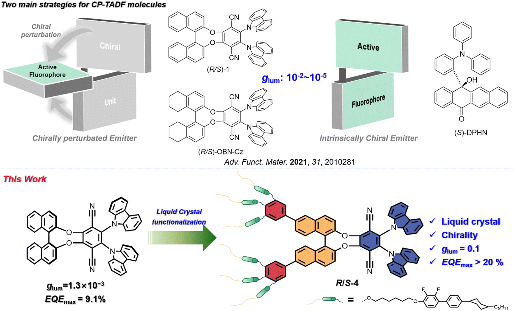
Circularly polarised luminescence (CPL) is a phenomenon leading to varying emission intensities of left- and right-circularly polarised light, which can provide information about the excited states of chiral molecular systems.1 Recently, circularly polarised light from molecular emitters has attracted much attention because of its applications in anti-glare displays, encrypted transmission, optical communication and three-dimensional (3D) displays.2–4 Compared to traditional methods in which a polariser and waveplate are employed, luminescent circularly polarising materials can generate circularly polarised light directly and hence have higher efficiencies in devices. To date, many CPL materials, including small organic molecules and polymers, have been developed5,6 and, depending on the emission mechanism, CPL materials are usually classified as emitting via fluorescence,7–11 photoluminescence12–16 or thermally activated delayed fluorescence (TADF).17–20 Spin statistics demonstrate that fluorescence can only harvest singlet excitons, and thus leads to relatively low internal quantum efficiency (IQE, 25%)21,22 and, while the theoretical IQE for phosphorescence is 100%, the high cost and the fact that there are rather few examples severely compromise their use.23,24 Thus, circularly polarised TADF (CP-TADF) materials become attractive for the realisation of CPL emission as, unlike most phosphorescent emitters, they are metal-atom free and yet still offer maximum theoretical IQE.Over the past five years, much progress has been achieved with CP-TADF materials, with two main design strategies being employed.25 The first method is where the chiral element is embedded in the fluorophore, defined as an intrinsically chiral CPL emitter,25,26 and Hirata and co-workers reported the first such example in 2015 with a chiral carbon sandwiched between the donor and acceptor moieties (S-DPHN, Fig. 1).20 More recently and using the same strategy, some research groups have developed many examples of inherently CP-TADF emitters (using axial, planar or point chirality), realising luminescence asymmetry factor (glum) values in the range of 10−3–10−2.27–29 Unfortunately, purification of this kind of CP-TADF molecule is very difficult (chiral HPLC or resolution through diastereoisomeric separation), making them a little less attractive.
 | ||
| Fig. 1 Strategies for CP-TADF molecules in the previous reports (top side) and the design principle of the enantiomers in this manuscript (bottom side). | ||
The second method uses chiral perturbation, where a chiral unit is placed in close proximity to the fluorophore. The simple preparation procedure of this approach (starting with commercially available, enantiopure products) greatly facilitates its large-scale synthesis and application and, to the best of our knowledge, most reported CP-TADF molecules have been designed via this approach.25 For example, Pieters and co-workers realised the CP-TADF molecule (R/S-1, Fig. 1) via integration of a TADF chromophore into a chiral binaphthol unit, giving a glum of 1.3 × 10⁻³ and an external quantum efficiency (EQEmax) of 9.1%.19 Based on this result, Zheng and co-workers varied the chiral unit to the related octahydrobinaphthol unit to achieve the CP-TADF material they labelled (R/S)-OBN-Cz (Fig. 1). Although such molecule exhibited a sharply increased EQEmax up to 32.6%, glum was still about 2.0 × 10−3.17,30 Compared to intrinsically chiral CPL emitters, CP-TADF molecules based on this latter strategy have so far shown relatively low values of glum, between 10−4 and 10−3.31 On the other hand, OLEDs based on CP-TADF materials were usually fabricated by vacuum deposition, which is a complicated procedure, has low materials usage and, because of the high temperatures employed, can occasionally lead to some racemisation. Thus, it is necessary to develop soluble CP-TADF molecules with both high glum and high emission efficiency.
According to the relationship between the luminescence asymmetry factor (glum) and the corresponding electronic transition, glum is given by:32,33
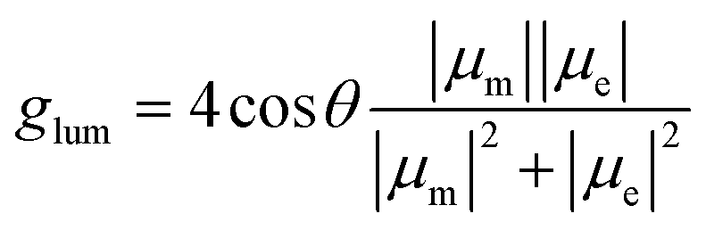
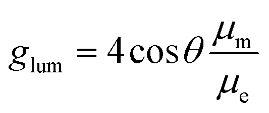
In this case, glum is proportional to μm but inversely proportional to μe. This means that a relatively high glum value requires a small μe, which unfortunately sacrifices the emission efficiency of the emitter. As such, achieving a balance between the emission efficiency and glum in CP-TADF materials remains a formidable challenge.
Recently, liquid crystals have aroused interest in the generation of circularly polarised light due to their excellent self-organisation properties34–36 and some groups have reported a high glum value by doping a chiral emitter into an achiral liquid crystal, proving that the liquid crystal can amplify the glum value.35,37 Very recently, Li et al. achieved a strong CPL signal of |glum| = 0.47 using the orientational order parameter of achiral dyes in cholesteric liquid crystal media.38 Our previous work also demonstrated that integrating liquid crystallinity and phosphorescence can lead to impressive values of glum of 10−2 in an OLED device.39 Encouraged by these results, a proof-of-concept, liquid-crystalline CP-TADF molecule was conceived in which the chiral TADF molecule (R/S-1) is employed as the emissive core due to its high emission efficiency and relatively simply preparation.19 It is then functionalised with six mesogenic moieties which are integrated into the binaphthol unit as two 3,4,5-trisubstituted phenyl rings to give enantiomers R/S-4 (Fig. 1). The pair of compounds shows symmetric CD and CPL signals as thin films, indicating their chirality in both the ground and excited states, and the glum values of the films prepared from R/S-4 are 10−1. Employing the TADF material 10-(4-((4-(9H-carbazol-9-yl)phenyl)sulfonyl)-phenyl)-9,9-dimethyl-9,10-dihydroacridine (CzAcSF) as the sensitiser, the resulting solution-processed OLED showed an impressive device performance with the maximum external quantum efficiency (EQEmax) of 21.2%.
Results and discussion
Synthesis and electrochemical properties
As depicted in Scheme S1 (ESI†), the key precursor – the di(bromophenyl) analogue of 1 – was prepared according to the previous publication.19 A typical Suzuki coupling reaction between the triply functionalised mesogenic moiety and compound 1-Br2 yielded the chiral enantiomers R/S-4 which were characterised by NMR spectroscopy, mass spectrometry and HPLC (Fig. S17–S23, ESI†). Both emitters possess good solubility in common organic solvents, such as toluene, dichloromethane and THF, and show good thermal stability, exhibiting a 5% weight loss at 385 °C (Fig. S1, ESI†). The redox behaviour of the materials was investigated by cyclic voltammetry (CV) in CH2Cl2 (Fig. S2, ESI†) and an irreversible oxidation potential (Eox) of 0.84 V was found for R-4 (as the enantiomers have identical physical properties, only R-4 is discussed in the text). The highest occupied molecular orbital (HOMO) energy level can then be calculated as –5.19 eV using the formula EHOMO = −(EOX + 4.8 − E1/2) in which ferrocene (E1/2 = 0.46 V) is used, as in ref. 40. The lowest unoccupied molecular orbital (LUMO) energy level can be inferred from the HOMO energy and the optical bandgap (Eoptg) is calculated from the absorption onset. Based on the formula ELUMO = EHOMO + Eoptg, the corresponding LUMO energy level is determined as −2.71 eV.Theoretical calculations
Density functional theory (DFT) and time-dependent DFT (TD-DFT) calculations were carried out to optimise the ground and excited state geometries (to simplify the molecular structure, the alkoxyl chains is omitted), using Gaussian 09 with the B3LYP functional and the def2-SVP basis set. The HOMO and LUMO density distributions, energy gaps, oscillator strengths, excited state energy and spin–orbit coupling matrix elements (〈S|HSOC|T〉) so obtained are shown in Fig. 2. The enantiomers clearly exhibit a distorted molecular geometry, which is beneficial to the spatial separation between the FMO (frontier molecular orbitals). Thus, the HOMO is located predominantly on the carbazole units, while the LUMO is located mainly on the phthalonitrile. According to previous reports,41 the 1,1′-binaphtyl moiety can utilise the chiral perturbation effect to realise circular polarisation, while the mesogenic unit has a negligible effect on the electronic distribution. To further understand the characters of the S0 → S1 and S0 → T1 transitions, natural transition orbital (NTO) analysis was performed for the excited state (Sn and Tn) using TD-DFT (Fig. 2(b)). Substantial overlap occurs between holes and particles in the S1 and T1 states, indicating that the singlet and triplet states are mainly endowed with local excitation (LE) properties. The spatial separation of FMOs leads to the small value of ΔEST required for TADF character, which is calculated to be 0.09 eV. A high spin–orbit coupling (SOC) matrix element of 〈S1|HSOC|T1〉 was evaluated to be 0.552 cm−1, implying different electronic structures of the S1 and T1 states and resulting in an effective reverse intersystem crossing (rISC) process between the T1 and S1 states (Table S1, ESI†). Notably, both 〈S1|HSOC|T2〉 and 〈S1|HSOC|T3〉 also have large SOC values, indicating that multiple rISC processes can occur in this molecule.42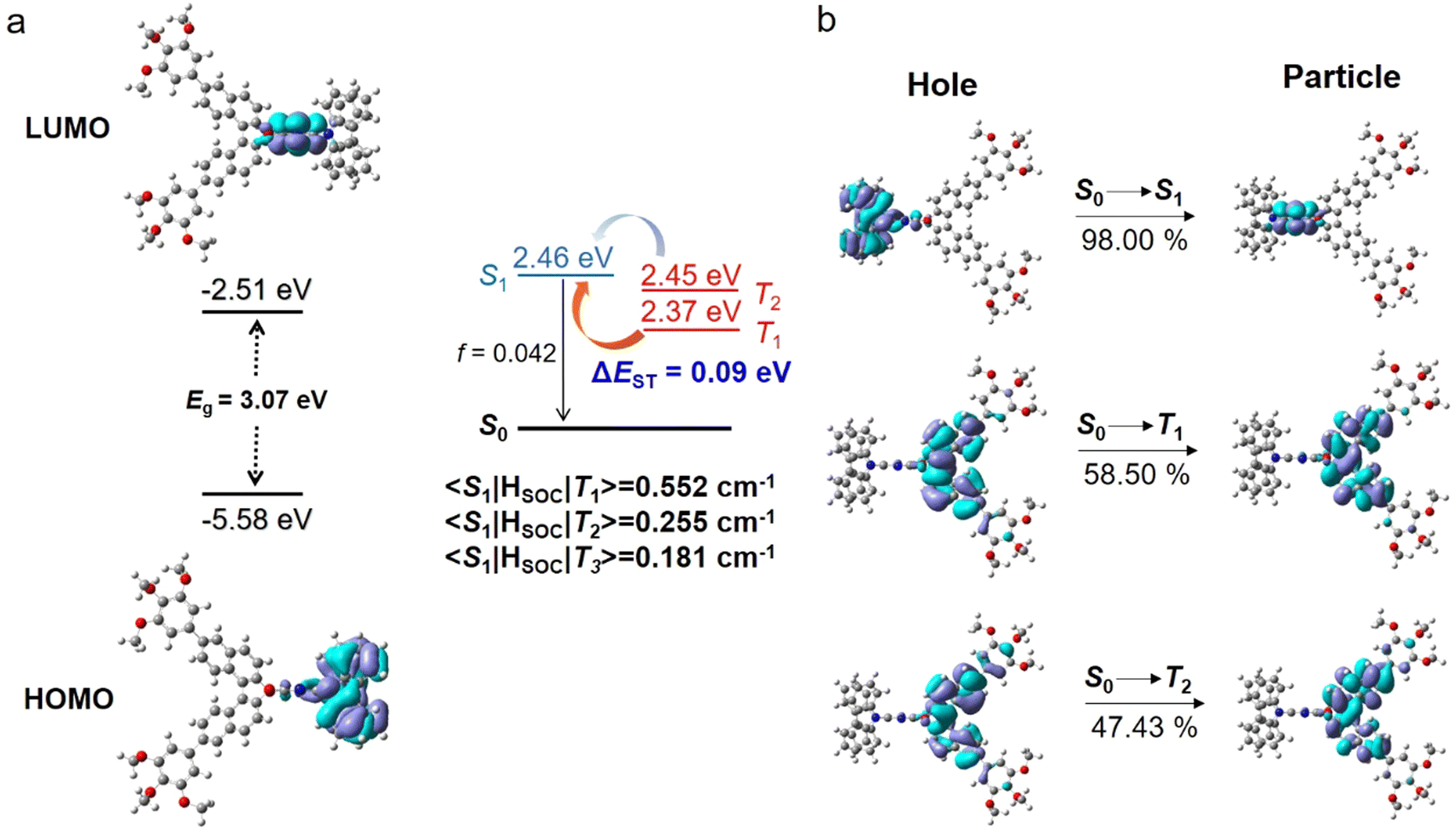 | ||
| Fig. 2 Distributions of: (a) frontier molecular orbitals (FMOs) and (b) natural transition orbitals (NTOs, hole/particle wave functions), as well as energy levels, oscillator strength (f), and spin–orbit coupling (SOC) constants for R-4 (S-4 is identical). | ||
Liquid crystal behaviour
The liquid crystal properties of the emitters were investigated by polarising optical microscopy (POM) (Fig. 3 and Fig. S3, ESI†), differential scanning calorimetry (DSC) (Fig. S4, ESI†) and small-angle X-ray scattering (SAXS) (Fig. 3 and Fig. S3, ESI†). Importantly, the thermal behaviour of the two enantiomers is, as expected, essentially identical. Thus, on heating from room temperature, DSC shows two transitions at 164.5 °C (ΔH ≈ 7 kJ mol−1) and at 184.8 °C (ΔH ≈ 11.5 kJ mol−1), which equate to around 1 kJ mol−1 and 2 kJ mol−1 per mesogenic group, respectively (Table S2, ESI†). Despite the high molecular weight of the material (>3500 g mol−1), the higher-temperature transition is perfectly reversible, while there is a small degree of supercooling in the lower-temperature transition. The absence of a large-enthalpy transition is consistent with the compound being in a mesophase at ambient temperature (i.e., there is no readily apparent melting/crystallisation event).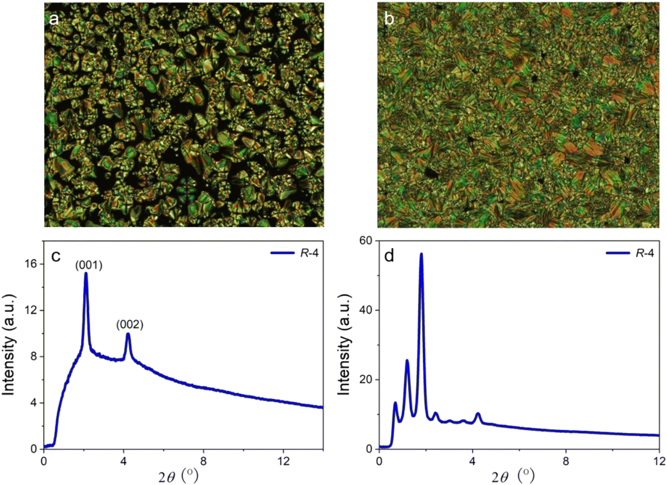 | ||
| Fig. 3 POM image of R-4 on cooling: (a) in the SmA* phase at 183 °C and (b) in the more ordered mesophase at 155 °C. SAXS pattern of R-4 on cooling: (c) in the SmA* phase at 173 °C and (d) in the more ordered mesophase at 148.4 °C. | ||
The higher-temperature transition is identified as the clearing point, above which the material shows optical extinction under crossed polarisers, but slow cooling below this temperature allows development of a focal-conic fan texture punctuated with optically extinct domains of homeotropic orientation characteristic of a SmA* phase (the phase is designated SmA* rather than simply SmA on account of the chiral nature of the compound, although this has no impact on the observed texture) with clear elliptical and hyperbolic defects evident, although weak striations are observed across the back of the fans. Further cooling leads to a phase transition in which much stronger striations or deformations are observed across the back of the fan texture, indicative of a mesophase with greater order. There is no change in the homeotropic domains indicating that molecular tilt has not been introduced, which may have explained the fragmented or striated focal conic texture at the phase transition. In addition, the lower temperature phase does not readily shear upon mechanical stress, again indicative of a phase with greater order.
SAXS data are consistent with the assignment of the upper phase as the SmA* phase, and a primary reflection is observed at 2θ = 2.12°, corresponding to the (001) reflection and a spacing of 41.6 Å. In addition, there is a (002) reflection at 2θ = 4.21° which corresponds to a spacing of 21.0 Å. The observation of a second-order reflection implies a greater degree of layer correlation than is commonly observed and is consistent with the weak striations in the optical texture. From published single crystal structures,43,44 it is possible to estimate the fully extended length of the molecule to be around 50 Å, and so with a measured SmA* spacing of ca. 42 Å, it is likely that some sort of bilayer organisation exists that may involve in the interdigitation of the two ortho-carbazole groups, which will be oriented perpendicular to the terephthalonitrile ring to which they are attached, perhaps also with some interdigitation and/or folding of the terminal pentyl chains.
For the lower-temperature phase, many more reflections are observed in the low-angle region in the range 0.68° ≤ 2θ ≤ 4.23°, corresponding to spacings of 129.8 Å ≤ d ≤ 20.9 Å. However, their appearance is not accompanied by the development of reflections at mid or wider angles, which would imply three-dimensional order. These low-angle reflections indicate a much greater degree of order, although the fact that the widths of the reflections are very similar to those seen in the pattern for the SmA* phase implies that this is a mesophase of sorts.
Photophysical properties
As the two compounds are related as enantiomers, R-4 is selected for detailed discussion. The UV-vis absorption and photoluminescent (PL) spectra of R-4 were performed both in solution and doped in mCP films (Fig. 4); the related data are summarised in Table 1. Two distinct absorption bands were detected in toluene solution, in which the very weak band at 425 nm is attributed to an intramolecular charge-transfer (ICT) transition, while the intense absorption band at 330 nm is ascribed as a π–π* transition. The emission peak was detected at 525 nm for R-4 in toluene solution and its broad, structureless profile indicates that it originates from a charge-transfer (CT) state. There is also evident solvatochromism and the 525 nm emission peak of R-4 in toluene red shifts to 589 nm in a much more polar solvent DMF, consistent with the stabilisation of the charge-separated excited state by more polar solvents and related to the strong intramolecular charge transfer ability of this material (Fig. S5, ESI†).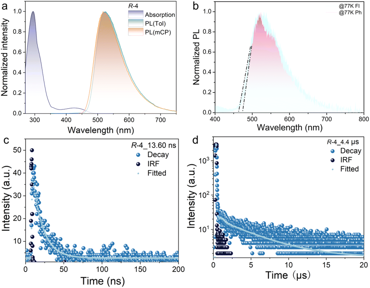 | ||
| Fig. 4 (a) UV-vis spectra and PL spectra of R-4 measured in toluene solution (10−5 M) and 5 wt% doped in mCP film (λex = 420 nm); (b) low-temperature fluorescence (Fl) and phosphorescence (Ph) of R-4 doped in mCP film (λex = 370 nm, delayed 2 ms); and (c) and (d) transient PL decay curves (λex = 420 nm) of 5 wt% R-4 doped in mCP film. | ||
| λ abs (nm) | λ em (nm) | λ Fl (nm) | λ Ph (nm) | ΔEST (eV) | τ p (ns) | τ d (μs) | PLQYc (%) | g PL (10−1) | E optg (eV) | |
|---|---|---|---|---|---|---|---|---|---|---|
| a Measured in toluene solution at room temperature. b Fluorescence and phosphorescence emission in toluene solution at 77 K and the calculated values for the onsets of fluorescence and phosphorescence. c In mCP films. d In film; Eoptg was calculated via Eoptg = 1240/λ, in which λ is collected from the band-edge absorption. | ||||||||||
| R-4 | 294, 431 | 524 | 525b (523)c | 533b (518)c | 0.05b (0.05)c | 13.60 | 4.4 | 51.3 | 0.8 | 2.48 |
| S-4 | 292, 431 | 523 | 524b (523)c | 533b (517)c | 0.06b (0.05)c | 13.69 | 4.7 | 53.7 | 1.1 | 2.45 |
The singlet (S1) and triplet (T1) energy values were obtained from low-temperature (77 K) fluorescence (Fl) and phosphorescence (Ph) measurements, respectively (Fig. S6, ESI†). According to the measured onset values, the S1 and T1 energy levels were evaluated to be 2.64 and 2.59 eV, respectively, so that the corresponding value of ΔEST is calculated to be 0.05 eV in toluene. These values are consistent with the computational data reported above and the observation of TADF characteristics.
Compared with the PL in solution, the emission spectrum of R-4 doped in a mCP film shows similar emission to the peak at 521 nm. According to the onset of both fluorescence and phosphorescence emission at low temperatures, the S1 and T1 energy levels of the doped film were evaluated to be 2.67 and 2.62 eV for R-4, respectively (Fig. 4(b)) in turn giving a value of 0.05 eV for ΔEST (similarly results were obtained for S-4, shown in Fig. S7, ESI†). This is good for rISC. To further confirm the TADF behaviour of the material, transient PL spectra of the doped mCP films were measured at room temperature. As shown in Fig. 4, R-4 displays both a clearly prompt decay with an exciton lifetime (τp) of 13.6 ns and a delayed decay with an exciton lifetime (τd) of 4.4 μs, indicating contributions from triplet excitons. Additionally, the temperature-dependent PL decay curves (recorded at 100, 200 and 300 K) showed an increase in the delayed component with increasing temperature, confirming the TADF mechanism (Fig. S8, ESI†). The photoluminescence quantum yield (PLQY) value of a film of 5 wt% R-4 in mCP is 51.3%, similar to that found with R/S-1.19 Based on the emission lifetime and PLQY, the photophysical constants of R-4, such as the rate constants of fluorescence (kr), nonradiative transition (knr), intersystem crossing (kISC), and reverse intersystem crossing (krISC), were calculated. As shown in Table S3 (ESI†), R-4 shows a reasonable value of krISC of 6.0 × 10⁴ s−1 and kd of 2.27 × 10⁵ s−1, which demonstrates that there is a minor effect on the emission properties after the introduction of the mesogenic groups.19
In order to investigate the ground and excited state chirality of R/S-4, the electron circular dichroism (CD) and circular polarisation luminescence (CPL) spectra of R/S-4 were evaluated in both solution and the as a film. Unfortunately, a very weak signal was obtained for the samples in toluene solution, whereas intense chiroptical signals were achieved for the films. As shown in Fig. S9 (ESI†), the symmetrical CD spectra indicate their enantiomeric relationship in the ground state and, in particular, the signal at ca. 420 nm indicates successful chiral perturbation between the chiral unit and the TADF chromophore.19 As shown in Fig. 5, the CPL spectra reflect the fact that this new TADF emitter can lead to chiral luminescence from the excited state. Impressive |glum| values as determined at the maximum emission peaks are about 0.04 and 0.05 for R-4 and S-4 in neat films, respectively, which are an order of magnitude greater than those of the parent core R/S-1 (1.3 × 10⁻³),19 which could originate from the integrated liquid crystal concept. Interestingly, the mCP-doped films present clearly increased |glum| values of 0.11 and 0.09 for R-4 and S-4, respectively (Fig. 5(c)). These increased values can be reasonably explained by suppressed intermolecular interaction. Thus, the strategy of introducing liquid crystallinity into the CP-TADF molecule is an effective method for amplification of the glum value.
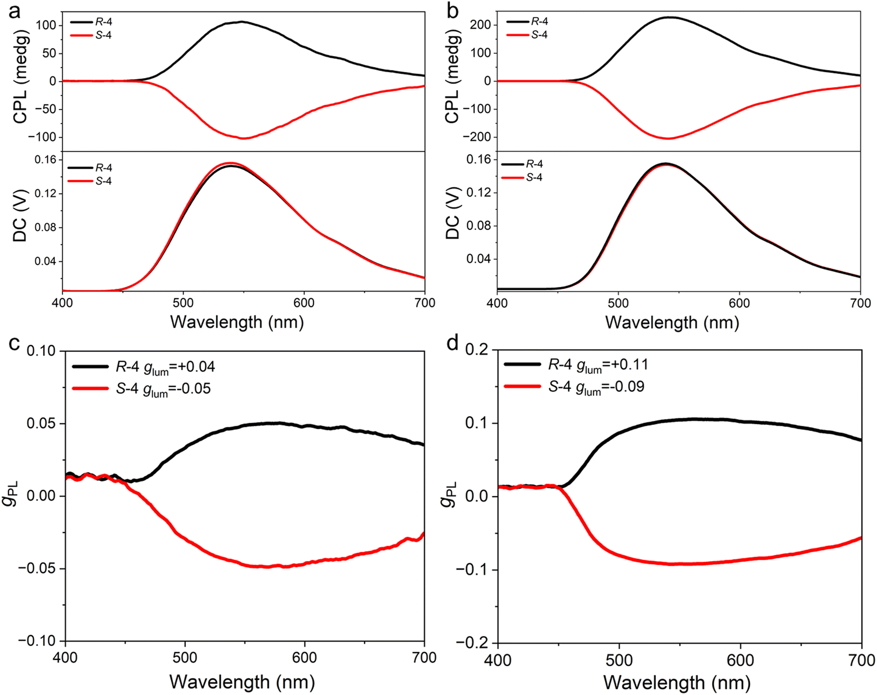 | ||
| Fig. 5 (a) CPL spectra and (c) glum values of CPL versus wavelength of R/S-4 in neat films; (b) CPL spectra and (d) glum values of CPL versus wavelength of R/S-4 in doped mCP films (λex = 340 nm). | ||
Device performance
In order to explore the electroluminescent (EL) properties of the materials, solution-processed devices were constructed with the following architecture: ITO/poly (3,4-ethylene-dioxythiophene): poly (styrene sulfonate) (PEDOT:PSS)/emitter layer (50 nm)/1,3,5-tris(3-pyridyl-3-phenyl)benzene (TmPyPB) (45 nm)/LiF (0.5 nm)/Al (120 nm) (Fig. S10a, ESI†). In this device structure, PEDOT:PSS and LiF are used as the hole-injection layer and the electron-injection layer, respectively, and TmPyPB is used as the electron-transport layer. Lithium fluoride (LiF) and aluminum (Al) were utilised as the electron-injection layer and cathode, respectively. The emission layer consists of the host mCP and the guest R/S-4, and the dopant concentrations were 5, 10 and 15 wt%. The relevant EL data are summarised in Table S4 (ESI†).As shown in the inset to Fig. S9c (ESI†), all devices show their emission peak at 526 nm, and CIE coordinates are found consistently at (0.31, 0.56), with the EL spectra being invariant with dopant concentration. In addition, emission from the mCP host is absent, indicating complete energy transfer between host and dopant. The change in current density–voltage-luminance (J–V–L) curves as a function of dopant concentration suggests that the carrier capture process is predominantly an emission mechanism in the devices and that increasing the dopant concentration apparently reduces the device performance significantly, likely due to concentration quenching. Thus, the device prepared with R-4 exhibits its best performance at 5 wt% of the emitter with an EQEmax of 10.2%, a maximum brightness (Lmax) of 444.9 cd m−2 and a current efficiency (CEmax) of 32.55 cd A−1 (Table S4 and Fig. S10, ESI†).
Performance of sensitised devices
To further improve the EL performance, the sensitiser concept was deployed. Previous work demonstrated that a TADF sensitiser can relieve exciton quenching and improve device performance via effective Förster energy transfer (FRET).45 Therefore, the sensitisers and emitters should be chosen carefully for effective FRET, informed by the equation for the rate of Förster energy transfer (kFET):46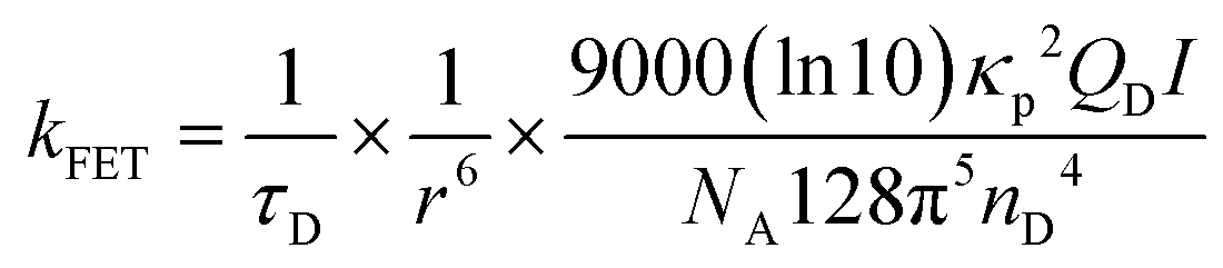
The magnitude of kFET is, therefore, greatly influenced by τD, r, QD, and I, where τD is the excited-state radiative lifetime of the sensitiser; r is the separation distance between sensitiser and emitter; κp is a parameter related to the relative orientation of the sensitiser and emitter dipoles; QD is the PLQY of the sensitiser; I is the spectral overlap integral between the emission of sensitisers and the absorption of the emitters; NA is the Avogadro constant and nD is the refractive index of the medium. Accordingly, decreasing τD and r, and/or increasing QD and I are important in achieving effective energy transfer. The magnitude of r can be enhanced by increasing the doping concentration of the sensitisers or emitters, although most TADF materials show reduced PLQY at higher doping concentration due to strong concentration quenching. Therefore, to maintain the luminescence performance of the emitter, low doping concentrations of the emitter and high doping concentrations of the sensitiser are usually adopted to ensure effective energy transfer.47
Based on the above discussion, 10-(4-((4-(9H-carbazol-9-yl) phenyl)sulfonyl)phenyl)-9,9-dimethyl-9,10-dihydroacridine (CzAcSF),48 a blue-emitting TADF luminophore with ΔEST = 0.07 eV was selected as the sensitiser. As depicted in Fig. S11 (ESI†), the PL spectrum of CzAcSF overlaps with the UV spectra of R/S-4, the prerequisite for FRET energy transfer. In order to reduce the high exciton density and related decay processes such as triplet–triplet annihilation (TTA) and triplet polaron annihilation (TPA), mCP is added to the emitter layer as the host to further increase the distance between the sensitiser and guest, and so suppress the Dexter energy transfer (DET).49 Using R-4 as the emitter, the emission band from CzAcSF gradually disappears with increasing dopant concentration (Fig. S12, ESI†), showing that there is efficient energy transfer between the TADF sensitiser and R-4. Furthermore, the transient PL decay curves of co-doped films show that the delayed component decreases with the increased dopant concentration, also implying an effective FRET process (Fig. S13, ESI†).49 In addition, the doped film displays increased PLQY from 50.8% (mCP: 1.5 wt% R-4) to 55.2% (mCP: 30 wt% CzAcSF: 1.5 wt% R-4).
Based on the above observations, both sensitised and non-sensitised solution-processed devices were fabricated for comparison. The device structure of the non-sensitised device is ITO/PEDOT:PSS/mCP: x wt% R-4 (50 nm)/TmPyPB (45 nm)/LiF (0.5 nm)/Al (120 nm) (where x = 0.5 wt% (D1), 1 wt% (D2) and 1.5 wt% (D3)). The sensitised device structure is ITO/PEDOT:PSS/mCP: 30 wt% CzAcSF: x wt% R-4 (50 nm)/TmPyPB (45 nm)/LiF (0.5 nm)/Al (120 nm) (where x = 0.5 wt% (S1), 1 wt% (S2) and 1.5 wt% (S3)). Use of such a low dopant concentration effectively suppresses Dexter electron transfer in the device. The dopant concentration of sensitiser was varied from 10 wt% to 30 wt%, and the corresponding device performances are summarised in Table S5 (ESI†). The device achieved its best performance at 30 wt%.
As the concentration of R-4 increases from 0.5 wt% to 1.5 wt%, the non-sensitised devices show values of EQEmax between 3.6% and 3.2% (Table 2). In the sensitised device, the EL spectra exhibit maximum emission at 510 nm, similar to the non-sensitised device (Fig. 6(c) inset, Table 2), consistent with the emission from the terminal emitter. This phenomenon also demonstrates that there is complete energy transfer between the host, sensitiser and dopant in the device. Relatively low turn-on voltages (Von) of 4.2 ± 0.2 V were detected for the TADF-sensitised devices which, intriguingly, showed excellent performance with EQEmax = 21.1%, Lmax = 2570 cd m−2 and CEmax = 62.9 cd A−1. Data for the related S-4 based devices are found in Fig. S14 and Table S6 (ESI†). The EQEmax of the sensitised device is, therefore, approximately six times higher than that of the non-sensitised device. The energy transfer and device emission processes are depicted graphically in Fig. S15 (ESI†). The electron–hole recombination on mCP produces singlet and triplet excitons. The singlet excitons in the host can transfer to both the sensitiser and terminal emitter by the FRET process, while the triplet exciton can transfer to the sensitiser via the DET process. Due to the rISC process, the triplet excitons of the sensitiser can be converted to singlet excitons, which can transfer to the terminal emitter by the FRET process. Eventually both singlet and triplet excitons can be achieved by the terminal emitter through the efficient FRET process and then achieve a high-performance sensitised fluorescent OLED. Unfortunately, the CPEL signal is very weak, which can be explained by the very low dopant concentration (Fig. S16, ESI†).
| Device | V on (V) | L max (cd m−2) | CEmax (cd A−1) | EQEmax | Peak (nm) | FWHM | CIE |
|---|---|---|---|---|---|---|---|
| D1 | 4.4 | 716 | 10.9 | 3.6 | 516 | 85.1 | (0.26, 0.51) |
| D2 | 4.4 | 443.1 | 10.8 | 3.3 | 516 | 80.2 | (0.26, 0.54) |
| D3 | 3.6 | 378 | 10.9 | 3.2 | 516 | 78.6 | (0.26, 0.53) |
| S1 | 4.0 | 1894 | 45.4 | 16.7 | 504 | 97.1 | (0.21, 0.39) |
| S2 | 4.4 | 2304 | 54.7 | 18.9 | 510 | 95.6 | (0.24, 0.45) |
| S3 | 4.4 | 2570 | 62.9 | 21.2 | 510 | 95.6 | (0.24, 0.45) |
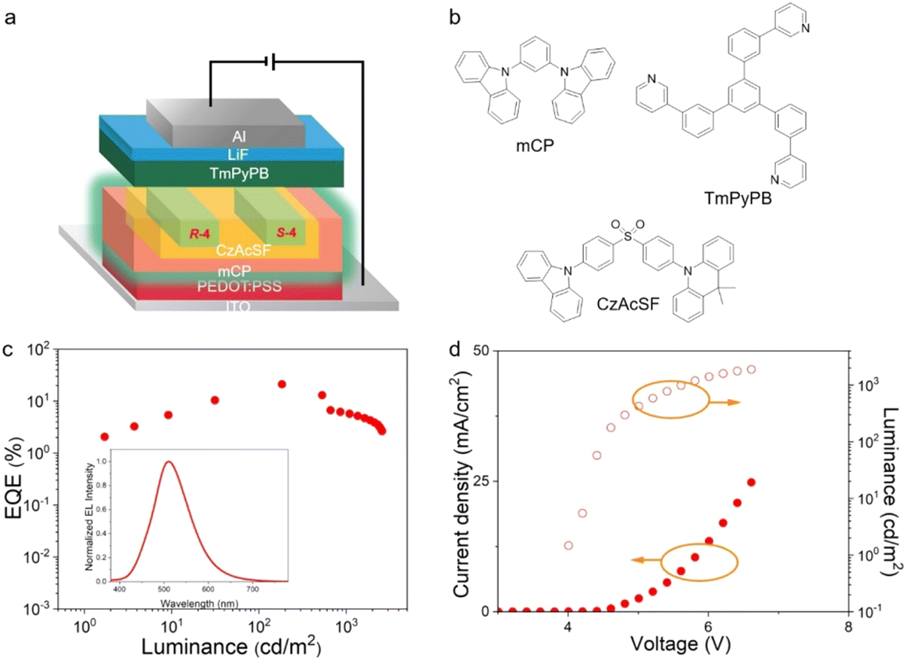 | ||
| Fig. 6 (a) Device architecture and (b) materials used in the devices; (c) EQE–current density (inset: EL spectra of the devices) and (d) current density–voltage–luminance curves of the sensitised devices with 1.5 wt% dopant concentration. | ||
Conclusions
In summary, an enantiomeric pair of liquid-crystalline CP-TADF molecules R/S-4 was prepared using the chiral perturbation strategy. They exhibited intense green emission, similar to the CP-TADF emission core, showing that the introduction of the mesogenic moieties has a negligible effect on the emission properties. A delayed component of emission was clearly detected for the molecules in solution and as a neat film. R/S-4 showed symmetrical CD and CPL signals as films and the glum values reached 10−1 in the doped film – two orders of magnitude higher than that found for the parent chromophore. This phenomenon demonstrates that liquid-crystallinity has a positive effect on amplification of glum. Impressively, the solution-processed sensitised OLED using R/S-4 as the dopants achieved a maximum EQE of 21.2%. As such, we report an effect strategy for amplifying the glum value of the CP-TADF molecule.Through the modification of a known binaphthol emitter to confer liquid crystal properties, a material with an intrinsically very high luminescence asymmetry has been realised. Furthermore, its incorporation into a sensitised, solution-processed OLED leads to a high device external quantum efficiency, being approximately six times more efficient than that of the non-sensitised device. Further work is required to understand the very positive effect of the liquid-crystalline modifications to R/S-4, but a hint may lie in the high value of the EQE compared to the device PLQY, which would suggest that, even at the rather low concentrations of R/S-4 used.
Author contributions
The project was conceived by YW, WZ and DWB. Experimental work was carried out by BH, QZ, QD, XY, SJC and WQ. Data were analysed by SJC, DWB, PD and YW. The manuscript was written by BH, QZ and DWB, and was edited by DWB, PD and YW.Conflicts of interest
There are no conflicts to declare.Acknowledgements
Financial support was from the National Natural Science Foundation of China (no. 22371020, 52073035, U1663229), the Special Programme for foreign talents in Changzhou City (CQ20224052) and the University of York. The authors also would like to thank the Analysis and Testing Center, NERC Biomass of Changzhou University, for their help on NMR measurements and Professor Youxan Zheng of Nanjing University for measurements of CPEL spectra.Notes and references
- F. S. Richardson and J. P. Riehl, Chem. Rev., 2002, 77, 773–792 CrossRef.
- J. R. Brandt, F. Salerno and M. J. Fuchter, Nat. Rev. Chem., 2017, 1, 0045 CrossRef CAS.
- J. Kumar, T. Nakashima and T. Kawai, J. Phys. Chem. Lett., 2015, 6, 3445–3452 CrossRef CAS PubMed.
- R. Farshchi, M. Ramsteiner, J. Herfort, A. Tahraoui and H. T. Grahn, Appl. Phys. Lett., 2011, 98, 162508 CrossRef.
- D. W. Zhang, M. Li and C. F. Chen, Chem. Soc. Rev., 2020, 49, 1331–1343 RSC.
- J. Han, S. Guo, H. Lu, S. Liu, Q. Zhao and W. Huang, Adv. Opt. Mater., 2018, 6, 1800538 CrossRef.
- J. Jimenez, L. Cerdan, F. Moreno, B. L. Maroto, I. Garcia-Moreno, J. L. Lunkley, G. Muller and S. de la Moya, J. Phys. Chem. C, 2017, 121, 5287–5292 CrossRef CAS PubMed.
- E. M. Sanchez-Carnerero, F. Moreno, B. L. Maroto, A. R. Agarrabeitia, M. J. Ortiz, B. G. Vo, G. Muller and S. de la Moya, J. Am. Chem. Soc., 2014, 136, 3346–3349 CrossRef CAS PubMed.
- D. Q. He, H. Y. Lu, M. Li and C. F. Chen, Chem. Commun., 2017, 53, 6093–6096 RSC.
- H. Sakai, T. Kubota, J. Yuasa, Y. Araki, T. Sakanoue, T. Takenobu, T. Wada, T. Kawai and T. Hasobe, J. Phys. Chem. C, 2016, 120, 7860–7869 CrossRef CAS.
- M. Li, Y.-F. Wang, D.-W. Zhang, D. Zhang, Z.-Q. Hu, L. Duan and C.-F. Chen, Sci. China Mater., 2020, 64, 899–908 CrossRef.
- T. Y. Li, Y. M. Jing, X. Liu, Y. Zhao, L. Shi, Z. Tang, Y. X. Zheng and J. L. Zuo, Sci. Rep., 2015, 5, 14912 CrossRef CAS PubMed.
- L. Norel, M. Rudolph, N. Vanthuyne, J. A. Williams, C. Lescop, C. Roussel, J. Autschbach, J. Crassous and R. Reau, Angew. Chem., Int. Ed., 2010, 49, 99–102 CrossRef CAS PubMed.
- Z. Jiang, J. Wang, T. Gao, J. Ma, Z. Liu and R. Chen, ACS Appl. Mater. Interfaces, 2020, 12, 9520–9527 CrossRef CAS PubMed.
- G. Qian, X. Yang, X. Wang, J. D. Herod, D. W. Bruce, S. Wang, W. Zhu, P. Duan and Y. Wang, Adv. Opt. Mater., 2020, 8, 2000775 CrossRef CAS.
- J. Han, S. Guo, J. Wang, L. Wei, Y. Zhuang, S. Liu, Q. Zhao, X. Zhang and W. Huang, Adv. Opt. Mater., 2017, 5, 1700359 CrossRef.
- Z. G. Wu, H. B. Han, Z. P. Yan, X. F. Luo, Y. Wang, Y. X. Zheng, J. L. Zuo and Y. Pan, Adv. Mater., 2019, 31, e1900524 CrossRef PubMed.
- W.-L. Zhao, Y.-F. Wang, S.-P. Wan, H.-Y. Lu, M. Li and C.-F. Chen, CCS Chem., 2022, 4, 3540–3548 CrossRef CAS.
- S. Feuillastre, M. Pauton, L. Gao, A. Desmarchelier, A. J. Riives, D. Prim, D. Tondelier, B. Geffroy, G. Muller, G. Clavier and G. Pieters, J. Am. Chem. Soc., 2016, 138, 3990–3993 CrossRef CAS PubMed.
- T. Imagawa, S. Hirata, K. Totani, T. Watanabe and M. Vacha, Chem. Commun., 2015, 51, 13268–13271 RSC.
- M. Pope, H. P. Kallmann and P. Magnante, J. Chem. Phys., 1963, 38, 2042–2043 CrossRef CAS.
- M. Baldo, D. O’brien, M. E. Thompson and S. R. Forrest, Phys. Rev. B: Condens. Matter Mater. Phys., 1999, 60, 14422–14428 CrossRef CAS.
- K. S. Yook and J. Y. Lee, Adv. Mater., 2012, 24, 3169–3190 CrossRef CAS PubMed.
- M. Y. Wong and E. Zysman-Colman, Adv. Mater., 2017, 29, 1605444 CrossRef PubMed.
- M. Li and C.-F. Chen, Org. Chem. Front., 2022, 9, 6441–6452 RSC.
- S.-P. Wan, H.-Y. Lu, M. Li and C.-F. Chen, J. Photochem. Photobiol., C, 2022, 50, 100500 CrossRef CAS.
- C. Liao, Y. Zhang, S. H. Ye and W. H. Zheng, ACS Appl. Mater. Interfaces, 2021, 13, 25186–25192 CrossRef CAS PubMed.
- W. Yang, N. Li, J. Miao, L. Zhan, S. Gong, Z. Huang and C. Yang, CCS Chem., 2022, 4, 3463–3471 CrossRef CAS.
- Z.-P. Yan, T.-T. Liu, R. Wu, X. Liang, Z.-Q. Li, L. Zhou, Y.-X. Zheng and J.-L. Zuo, Adv. Funct. Mater., 2021, 31, 2103875 CrossRef CAS.
- F.-M. Xie, J.-X. Zhou, X.-Y. Zeng, Z.-D. An, Y.-Q. Li, D.-X. Han, P.-F. Duan, Z.-G. Wu, Y.-X. Zheng and J.-X. Tang, Adv. Opt. Mater., 2021, 9, 2100017 CrossRef CAS.
- L. Zhou, F. Ni, N. Li, K. Wang, G. Xie and C. Yang, Angew. Chem., Int. Ed., 2022, 61, e202203844 CrossRef CAS PubMed.
- E. M. Sanchez-Carnerero, A. R. Agarrabeitia, F. Moreno, B. L. Maroto, G. Muller, M. J. Ortiz and S. de la Moya, Chem, 2015, 21, 13488–13500 CrossRef CAS PubMed.
- Z.-L. Gong, X. Zhu, Z. Zhou, S.-W. Zhang, D. Yang, B. Zhao, Y.-P. Zhang, J. Deng, Y. Cheng, Y.-X. Zheng, S.-Q. Zang, H. Kuang, P. Duan, M. Yuan, C.-F. Chen, Y. S. Zhao, Y.-W. Zhong, B. Z. Tang and M. Liu, Sci. China: Chem., 2021, 64, 2060–2104 CrossRef CAS.
- Y. Li, K. Liu, X. Li, Y. Quan and Y. Cheng, Chem. Commun., 2020, 56, 1117–1120 RSC.
- K. Watanabe, I. Osaka, S. Yorozuya and K. Akagi, Chem. Mater., 2012, 24, 1011–1024 CrossRef CAS.
- B. A. San Jose, S. Matsushita and K. Akagi, J. Am. Chem. Soc., 2012, 134, 19795–19807 CrossRef CAS PubMed.
- D. Xu, X. Hua, C. Liu, J. Luo, W. H. Zheng and Y. Cheng, ACS Appl. Mater. Interfaces, 2023, 15, 25783–25790 CrossRef CAS PubMed.
- Y. Li, Y. Chen, H. Li, C. Liu, L. Li, Y. Quan and Y. Cheng, Angew. Chem., Int. Ed., 2023, e202312159 CAS.
- P. Fan, Z. Fang, S. Wang, Q. Dong, C. Xiao, A. J. McEllin, D. W. Bruce, W. Zhu and Y. Wang, Chin. Chem. Lett., 2023, 34, 107934 CrossRef CAS.
- A. K. Gupta, W. Li, A. Ruseckas, C. Lian, C. L. Carpenter-Warren, D. B. Cordes, A. M. Z. Slawin, D. Jacquemin, I. D. W. Samuel and E. Zysman-Colman, ACS Appl. Mater. Interfaces, 2021, 13, 15459–15474 CrossRef CAS PubMed.
- Z. Liu, Z. Jiang, C. He, Y. Chen and Z. Guo, Dyes Pigm., 2020, 181, 108593 CrossRef CAS.
- C. Lin, P. Han, S. Xiao, F. Qu, J. Yao, X. Qiao, D. Yang, Y. Dai, Q. Sun, D. Hu, A. Qin, Y. Ma, B. Z. Tang and D. Ma, Adv. Funct. Mater., 2021, 31, 2106912 CrossRef CAS.
- A. F. Suleymanova, M. Z. Shafikov, A. C. Whitwood, R. Czerwieniec and D. W. Bruce, J. Mater. Chem. C, 2021, 9, 6528–6535 RSC.
- Y. Zhu, S. Zeng, B. Li, A. J. McEllin, J. Liao, Z. Fang, C. Xiao, D. W. Bruce, W. Zhu and Y. Wang, ACS Appl. Mater. Interfaces, 2022, 14, 15437–15447 CrossRef CAS PubMed.
- D. Zhang, L. Duan, C. Li, Y. Li, H. Li, D. Zhang and Y. Qiu, Adv. Mater., 2014, 26, 5050–5055 CrossRef CAS PubMed.
- A. R. Clapp, I. L. Medintz and H. Mattoussi, ChemPhysChem, 2006, 7, 47–57 CrossRef CAS PubMed.
- Y. Wang, J. H. Yun, L. Wang and J. Y. Lee, Adv. Funct. Mater., 2021, 31, 2008332 CrossRef CAS.
- I. H. Lee, W. Song, J. Y. Lee and S.-H. Hwang, J. Mater. Chem. C, 2015, 3, 8834–8838 RSC.
- X. Song, D. Zhang, Y. Lu, C. Yin and L. Duan, Adv. Mater., 2019, 31, e1901923 CrossRef PubMed.
Footnote |
| † Electronic supplementary information (ESI) available: Techniques used; the synthesis of the materials (and their characterisation) along with details of thermal, photophysical and device properties. See DOI: https://doi.org/10.1039/d3mh01736b |
| This journal is © The Royal Society of Chemistry 2024 |