
Real-time correlation of crystallization and segmental order in conjugated polymers†
Shaochuan
Luo
 abc,
Yukun
Li
b,
Nan
Li
c,
Zhiqiang
Cao
d,
Song
Zhang
d,
Michael U.
Ocheje
e,
Xiaodan
Gu
d,
Simon
Rondeau-Gagné
e,
Gi
Xue
b,
Sihong
Wang
cf,
Dongshan
Zhou
*b and
Jie
Xu
*cf
abc,
Yukun
Li
b,
Nan
Li
c,
Zhiqiang
Cao
d,
Song
Zhang
d,
Michael U.
Ocheje
e,
Xiaodan
Gu
d,
Simon
Rondeau-Gagné
e,
Gi
Xue
b,
Sihong
Wang
cf,
Dongshan
Zhou
*b and
Jie
Xu
*cf
aSchool of Chemistry and Chemical Engineering, Nanjing University of Science and Technology, Nanjing, 210094, P. R. China
bDepartment of Polymer Science and Engineering, State Key Laboratory of Coordination Chemistry, Key Laboratory of High Performance Polymer Material and Technology, MOE, School of Chemistry and Chemical Engineering, Nanjing University, Nanjing, Jiangsu 210023, China. E-mail: dzhou@nju.edu.cn
cPritzker School of Molecular Engineering, University of Chicago, Chicago, Illinois 60637, USA
dSchool of Polymer Science and Engineering, Center for Optoelectronic Materials and Devices, University of Southern Mississippi, Hattiesburg, Mississippi 39406, USA
eDepartment of Chemistry and Biochemistry, University of Windsor, Windsor, Ontario N9B3P4, Canada
fNanoscience and Technology Division, Argonne National Laboratory, Lemont, Illinois 60439, USA. E-mail: xuj@anl.gov
First published on 4th October 2023
Abstract
Modulating the segmental order in the morphology of conjugated polymers is widely recognized as a crucial factor for achieving optimal electronic properties and mechanical deformability. However, it is worth noting that the segmental order is typically associated with the crystallization process, which can result in rigid and brittle long-range ordered crystalline domains. To precisely control the morphology, a comprehensive understanding of how highly anisotropic conjugated polymers form segmentally ordered structures with ongoing crystallization is essential, yet currently elusive. To fill this knowledge gap, we developed a novel approach with a combination of stage-type fast scanning calorimetry and micro-Raman spectroscopy to capture the series of specimens with a continuum in the polymer percent crystallinity and detect the segmental order in real-time. Through the investigation of conjugated polymers with different backbones and side-chain structures, we observed a generally existing phenomenon that the degree of segmental order saturates before the maximum crystallinity is achieved. This disparity allows the conjugated polymers to achieve good charge carrier mobility while retaining good segmental dynamic mobility through the tailored treatment. Moreover, the crystallization temperature to obtain optimal segmental order can be predicted based on Tg and Tm of conjugated polymers. This in-depth characterization study provides fundamental insights into the evolution of segmental order during crystallization, which can aid in designing and controlling the optoelectronic and mechanical properties of conjugated polymers.
New conceptsThis research harnesses the power of a unique fusion between ultra-fast scanning calorimetry (FSC) and micro-Raman spectroscopy to unravel the disparity between segmental ordering and crystallinity in conjugated polymers (CPs). Recently, the importance of segmental order in the morphology of CPs for achieving optimal electronic properties and mechanical deformability has been recognized. Thus, a comprehensive understanding of how highly anisotropic conjugated polymers form segmentally ordered structures with ongoing crystallization is essential, yet currently elusive due to limited control of the degree of segmental order and real-time molecular scale characterization. Through this advanced characterization technology, our work quantitatively reveals the interplay between segmental order and crystallization in CPs. Meticulous experiments with CPs of diverse backbones and side chains uncover a recurring phenomenon: the degree of segmental order reaches a saturation plateau at approximately 60–80% of maximum crystallinity. Furthermore, our research extracts a method to predict optimal annealing conditions for desired segmental order in CPs, providing insights into why CPs with lower crystallinity can still deliver outstanding performance. This work introduces a novel characterization technology to materials science, offering a framework for manipulating and understanding CPs and paving the way for advanced materials with tailored functionalities. |
Introduction
Functional properties of polymeric materials are to a large extent determined by their structure and morphology. In recent years, conjugated polymers (CPs) with unique optoelectronic properties and viscoelasticity have undergone remarkable development as promising materials for a wide range of applications from skin-like electronics and bioelectronics to large-area printed flexible organic photovoltaics and energy storage technologies.1–5 Their interchain couplings through π–π interactions between backbones and dispersion forces among side chains often result in complex morphologies, which can vary from disordered amorphous states to crystalline states with ordered lamellae.6In general, the degree of structural ordering of CPs dramatically impacts the ability of the π-conjugated electronic states to delocalize.7,8 The chain segmental couplings for local chain dynamics and motions substantially affect their electronic property and mechanical property.9,10 In the past decade, with the advent of more complex monomer structures, researchers found that, instead of long-range ordering (i.e., crystalline packing), the local segmental order (e.g., co-facially stacked planar backbone segments with tie polymer chains) can enable efficient long-range charge transport in a near amorphous state.11–13 This unique charge transport mechanism might result from the high coplanarity of rigid backbone with long conjugation length, which in turn allows CPs to have more design space for coupling new functions, such as mechanical softness and stretchability, while maintaining electronic performance.14 It is immediately evident that the segmental order strongly depends on the chain rearrangement, especially the crystallization process, during deposition and post-thermal treatment.15 However, the interplay between segmental order and crystallinity, and the impacts of segmental order on electrical and thermodynamic properties in CPs remains unclear. For decoupling these, the difficulty comes from limited control of the degree of segmental order and real-time molecular scale characterization.
It is extremely hard to generate a series of samples with a continuum in the degree of structural ordering in CP thin films due to the fast crystallization kinetics of CPs. In general, the semicrystalline morphology of CP films is formed during the solution deposition and post-treatment processes. The rapid solution-coating process typically drives the polymer assembly to happen far from equilibrium, resulting in significant structural variabilities in ways that are hard to control, and usually with a low degree of structural ordering in the microstructure.16–19 Thermal annealing is often performed on fresh-coated CP films at moderate temperatures to further increase the structural ordering, but can only provide limited states of crystallized morphology.20–23 Therefore, a nontraditional method is needed. To this end, fast scanning calorimetry (FSC), which is an advanced thermodynamic characterization method, can provide rapid heating/cooling scanning with rates up to 106 K s−1 to kinetically trap CP films from completely amorphous to structurally ordered crystalline with continuous intermediate states.24–26 By measuring the melting enthalpy of the crystalline region during each state, the evolution of the crystallization process can be quantitatively recorded. This makes FSC an ideal method for precisely manipulating the degree of structural ordering in CP films and exploring the difference between crystalline ordering and segmental order.
The microstructure of CP films is inhomogeneous and has film-to-film variation, which hinders the interpretation of subtle changes in segmental order through easy experiments. To avoid these issues, in situ probing of the structural order at the segmental level is required during the structural manipulation by FSC. Raman spectra of the CP films are highly sensitive to subtle changes in molecular properties and conditions due to the interconnection between the distribution of electron density in the π-system and the positions of the nuclei in the segmental chain.27 This provides useful insight into the structural segmental order of the CPs.28–33 As such, we integrate a microscope Raman spectroscopy as the structural probing station with a stage-type FSC as the structural manipulation station to in situ characterize the segmental order in CP films during the precisely controlled structural manipulation (Fig. 1 and ESI,† Fig. S1). Moreover, since FSC can record the melting enthalpy of the crystalline region, this integrated platform can capture the evolution of segmental order and crystallization process simultaneously in a quantitative manner, which is the key to studying their relationship and revealing their influence on charge transport and thermodynamic properties.
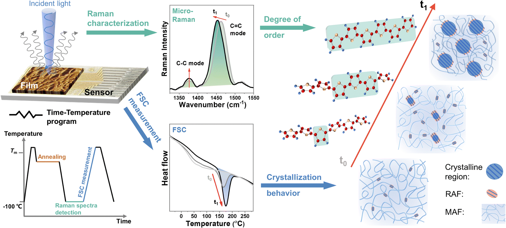 | ||
Fig. 1 Modulating and probing microstructure of conjugated polymers by integrated ultrafast calorimetry and micro-Raman spectroscopy. Left: Schematic of this integrated technique. The time-temperature program used in this study was carried out by the chip sensor temperature controller. The growth of crystalline domain was identified by the evolution of melting peak collected through FSC. The degree of segmental order was analyzed by the Raman shift of C![[double bond, length as m-dash]](https://www.rsc.org/images/entities/char_e001.gif) C modes through resonant micro-Raman spectroscopy. C modes through resonant micro-Raman spectroscopy. | ||
In this study, we characterized the segmental order of CPs across their entire structure evolution from a completely amorphous state to the highest-crystallized morphology in the time scale from 10−3 s to 104 s, and revealed the influences of segmental order and long-range crystalline order on CP's charge carrier transport and chain segmental dynamics. Two CP systems with different crystallization behaviors were studied by using the combination of FSC with in situ resonant micro-Raman spectroscopy. The first system is CP with different backbone structures, including poly(3-alkylthiophenes) (P3ATs) and poly(diketopyrrolopyrrole-thiophene) (PDPPT). The second system is CP with different side chain structures (i.e., branching points and lengths). Our results unravel a generally existing phenomenon that the degree of segmental order no longer changes when the relative degree of crystallinity (RDoC) reaches around 60–80%, which is seen from all CPs we tested. This knowledge is crucial for guiding the design of packing structures to couple desirable thermal dynamic properties and electronic properties in CPs.
Results and discussion
Tracking the evolution of segmental order during isothermal crystallization
To precisely control the morphology evolution with continuous intermediate states and avoid any impact of thermal history, the CPs were first quenched into a fully disordered amorphous state and then gradually rearranged into an ordered structure during isothermal crystallization. To conduct this study, we followed the time-temperature program illustrated in Fig. 1. Specifically, the sample was first melted down and then quenched to a designed temperature for thermal annealing with varying time durations. To prevent chain reorganization during temperature jump procedures for all FSC measurements, a cooling/heating rate of 10![[thin space (1/6-em)]](https://www.rsc.org/images/entities/char_2009.gif) 000 K s−1 was used. For Raman characterization, we performed measurements at a temperature of −100 °C under a nitrogen environment to suppress heating caused by the laser. After Raman structure characterization, the crystallization state was recorded by FSC through the last heating scan. Here, with ongoing crystallization, on the one hand, the melting temperature and the enthalpy of the melting peaks varied with time and temperature, reflecting the evolution of the crystalline phase; on the other hand, the CC mode peak position shifted with crystallization time and temperature, which associated with the segmental order of the polymer backbone, such as co-planarity and conjugation length.27,28
000 K s−1 was used. For Raman characterization, we performed measurements at a temperature of −100 °C under a nitrogen environment to suppress heating caused by the laser. After Raman structure characterization, the crystallization state was recorded by FSC through the last heating scan. Here, with ongoing crystallization, on the one hand, the melting temperature and the enthalpy of the melting peaks varied with time and temperature, reflecting the evolution of the crystalline phase; on the other hand, the CC mode peak position shifted with crystallization time and temperature, which associated with the segmental order of the polymer backbone, such as co-planarity and conjugation length.27,28
PDPPT and P3HT are selected as two model polymers with two different representative crystallization mechanisms for this study. PDPP-based donor–acceptor CPs have more planar backbone conformation and exhibit extended chain crystallization behavior with faster kinetics, while P3HT has a relatively flexible backbone that typically crystallizes into folded chain lamella at a slower rate.14 Using the time-temperature method illustrated in Fig. 1, the heating curves of samples after crystallizing at different temperatures for different durations were recorded (as ESI,† Fig. S2 and S3). As summarized in Fig. 2(a) and (b), the area of melting peaks steadily increased with crystallization time from 0.01 s to thousands of seconds, eventually reaching a saturation region. All the samples studied reached the final plateau (saturation region) before 5000 s (Fig. 2(a) and (b)) so that the melting peak area at the crystallization time of 5000 s was used as the maximum attainable melting enthalpy at each temperature. The maximum melting enthalpies of P3HT and PDPPT-C2C10C12 were obtained at the highest values at crystallization temperatures of 120 °C and 190 °C, respectively, indicating there are optimal isothermal crystallization temperatures (T*) for obtaining the highest crystallinity of the samples.
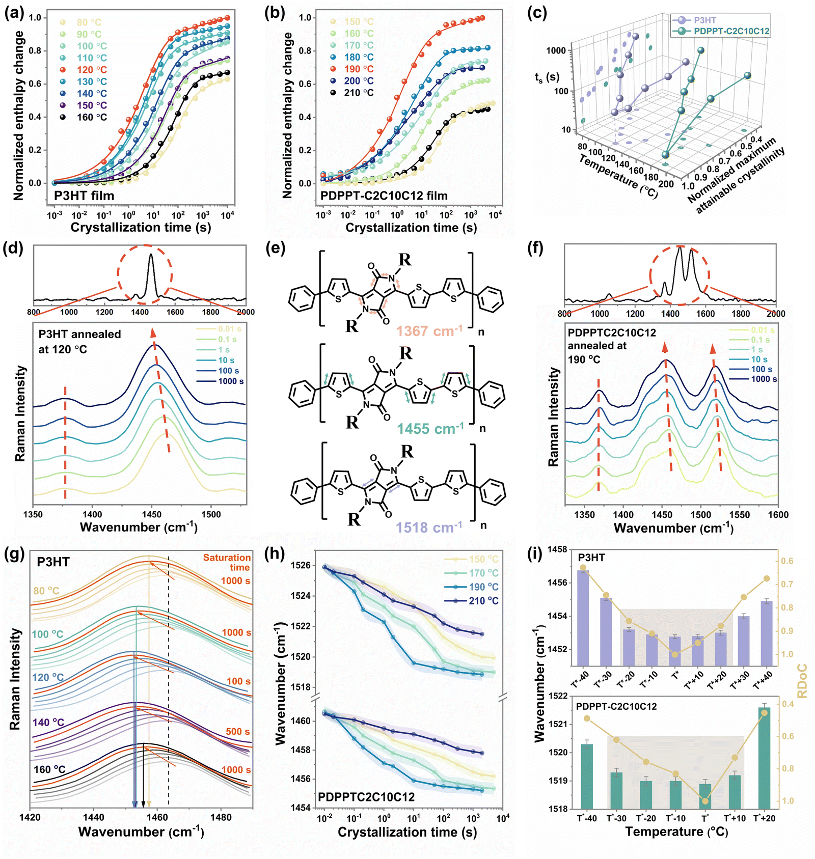 | ||
| Fig. 2 The evolution of the segmental order of P3HT and PDPPT-C2C10C12 during the isothermal crystallization. Normalized melting enthalpy change of (a) P3HT film and (b) PDPPT-C2C10C12 film as a function of the crystallization time. (c) The variations of ts and normalized maximum attainable crystallinity of P3HT and PDPPT-C2C10C12 films with crystallization temperatures. (d) Raman spectra of P3HT film crystallized at 120 °C. (e) Diagram illustrating the dominant bond stretches associated with the main Raman active vibrational modes of PDPPT-based polymers centered around 1367, 1455 and 1518 cm−1. (f) Raman spectra of PDPPT-C2C10C12 film crystallized at 190 °C for different time. (g) The shifts of CC mode of P3HT film with crystallization time when crystallized at different temperatures. The gradience in color from light to deep indicates the crystallization time from 0.01 s to 3000 s. The dashed line and solid lines indicate the wavenumber of CC mode at a fully amorphous state and final saturation state at different crystallization temperatures, respectively. (h) The variations of CC modes of PDPPT-C2C10C12 film with crystallization time when crystallized at different temperatures. (i) The saturated wavenumbers of CC modes and RDoC of P3HT and PDPPT-C2C10C12 films at different crystallization temperatures. | ||
Conjugated polymer's crystallinity can be precisely controlled by either the isothermal temperature or time. The time (ts) that polymers crystallize to their maximum under different isothermal temperatures was determined as the time point of intersection between the extrapolation line in the transition region and the line from the saturation region (ESI,† Fig. S4). The relative degree of crystallinity (RDoC) was then calculated by normalizing it to the highest crystallinity the polymer can reach. Fig. 2(c) summarizes the ts and normalized maximum attainable crystallinity of P3HT and PDPPT-C2C10C12 film crystallized at different temperatures. A bell-shaped curve was observed, where the lowest values of ts and the highest values of crystallinity were obtained at 120 °C for P3HT and 190 °C for PDPPT-C2C10C12, respectively. Moreover, the crystallinity of samples crystallized at low or high temperatures was only 40% to 60% of those crystallized at T*. In addition, ts increased from around 10 s to around 1000 s when crystallization temperatures varied from T* to unflavored temperatures. For instance, the ts of PDPPT-C2C10C12 film decreases from ∼800 s to ∼20 s when the crystallization temperature increases from 150 °C to 190 °C. These results demonstrate the significant differences in crystallization kinetics and crystallinity that can be achieved through the precise control of crystallization temperature and time.
The Raman spectra of carbon–carbon bond stretching were analyzed to show the variation of segmental order during crystallization. The peaks at 1378 cm−1 (related to C–C intra-ring stretch mode) and ∼1454 cm−1 (related to symmetric CC stretch mode) in the P3HT film were monitored to probe the π-electron delocalization (conjugation length) of P3HT molecules (ESI,† Fig. S5).28 A typical Raman spectrum of P3HT film excited at 488 nm and the variations of CC mode and C–C mode with crystallization time at a temperature of 120 °C are shown in Fig. 2(d). The CC mode shows a noticeable change, with the maximum peak position shifting from ∼1462 cm−1 to ∼1453 cm−1, as crystallization proceeds from 0.01 s to 3000 s. For PDPPT-based film, three major peaks are monitored, with the peak at ∼1367 cm−1 related to C–C and C–N symmetric stretches of the DPP acceptor, the peak at ∼1455 cm−1 related to thiophene intra-unit backbone CC symmetric stretch, and the peak at ∼1518 cm−1 related to CC symmetric stretch of the DPP acceptor (Fig. 2(e)). Similar to observations of the P3HT film, when PDPPT-C2C10C12 film crystallized at 190 °C, two backbone CC peaks shifted gradually to lower wavenumbers with crystallization as shown in Fig. 2(f). According to the effective conjugation coordinate model (ECCM), as the conjugation length of a polymer increases, the force constant originating from the interaction between the central unit and the units at a distance from the central one along the one-dimensional lattice increases, which in turn reduces the total force constant, causing the Raman mode to be downshifted in wavenumber with increasing conjugation length and segmental order.27 Thus, observations of the shifting of CC peaks to lower wavenumbers imply increases in conjugation length, backbone planarity and segmental order of samples during crystallization.27,34
The detailed evolution of the segmental order during the isothermal crystallization was probed to give the correlation of the segmental order with crystallinity. The changes in peaks in P3HT films isothermally crystallized at different temperatures are presented in ESI,† Fig. S6 and summarized in Fig. 2(g), exhibiting a similar trend but with varying time to reach saturated wavenumbers and different final Raman shifts. More specifically, with ongoing crystallization, CC peak shifts to a similarly saturated wavenumber (∼1453 cm−1) by different time (from 100 s to 1000 s) at temperatures ranging from 100 °C to 140 °C. However, when crystallization temperatures were set as 80 °C or 160 °C, the CC peak shifts to higher wavenumbers of ∼1457 cm−1 and ∼1455 cm−1 through the crystallization time of more than 1000 s, respectively, indicating a less ordered structure formed even at a longer time. As shown in Fig. 2h and ESI,† Fig. S7, the Raman shifts of CC modes in the PDPPT-C2C10C12 film exhibit a similar trend to those in the P3HT films. Crystallizing at temperatures of 170 °C and 190 °C leads to the most ordered structure as indicated by the lowest wavenumber of CC modes, while less ordered structures are formed at temperatures of 150 °C and 210 °C. Combining the large difference of crystallinity when crystallization temperature varies from 190 °C to 170 °C as shown in Fig. 2(b), we propose that the segmental order could saturate with ongoing crystallization. Thus, the relationship between the segmental order and the crystalline order of these two CPs was extracted in Fig. 2(i). A clear disparity between the crystallinity and the segmental order is observed. Here, the degree of crystallinities was modulated by isothermal temperatures, while the smaller wavenumbers of CC modes indicate a higher degree of segmental order in both P3HT and PDPPTC2C10C12 films. The results indicate that the degree of segmental order increases with increasing crystallinity but reaches its maximum value before the maximum crystallinity is achieved. This information can be useful in choosing a tailored temperature and time in the treatment to obtain an ordered structure and desired crystallinity. At the optimal temperature T*, an ordered structure can be obtained less than 100 s with the highest crystallinity. Meanwhile, since relative lower crystallinity is desired for the highly stretchable semiconducting film,11,35–37 ordered structure could also be obtained at temperatures from T* −20 °C to T* +20 °C for P3HT and T* −30 °C to T* +10 °C for PDPPTC2C10C12 with lower crystallinity (∼0.8 to 1 and ∼0.6 to 1), but longer crystallization time (∼800 to 2000 s).
In addition to studying CPs with different backbone structures, we also modified the side-chain structures of these two model conjugated polymers and conducted similar studies on them to explore the universality of the observed discrepancy between segmental order and crystalline order (Fig. 3). Both the side chain length and branching position are important factors in determining the chain packing structure and thin film structural ordering.38–40 Here, P3ATs with different side-chain branching positions (Fig. 3(a)) and the PDPPT-based CPs with different side-chain lengths (Fig. 3(b)) were synthesized and studied. We first investigated the saturated wavenumbers of samples crystallized at different temperatures. As shown in ESI,† Fig. S8–S12 and summarized in Fig. 3(c) and (d), the saturated wavenumbers of CC modes reach their lowest values when the samples are crystallized in a temperature range (TR I) around T*. For instance, the TR I of PDPPT-C2C6C8 film lies in T* −40 °C to T* (180 °C to 220 °C), while the TR I of PDPPT-C2C12C14 film lies in T* −20 °C to T* +10 °C (150 °C to 180 °C). Combining the RDoC studied by FSC (ESI,† Fig. S11–S15) with insights from Raman spectra data, we found that the normalized maximum attainable crystallinities of samples are beyond 80% and 60% when P3AT and PDPPT-based films crystallized at TR I, respectively (see ESI,† Table S1). Thus, we proposed that the segmental ordered structure could be formed through crystallization when the RDoC reaches 80% and 60% for P3AT and PDPPT-based films, respectively. To verify this hypothesis, real-time characterizations of both wavenumbers of CC modes and crystallinities of P3AT and PDPPT-based films were summarized in Fig. 3(e) and (f). For P3AT films, the segmental order gradually increases with increasing RDoC, while the Raman shift of CC modes saturates at a plateau when the RDoC of the film is above ∼80%, indicating a similar segmental order at high RDoC. For PDPPT-based films, as shown in Fig. 3(f), the positive correlation between segmental order and crystallinity becomes less evident when the RDoC reaches ∼60%. These observations indicate that the segmental ordered structure in a semicrystalline network formed in the absence of high crystallinity and could be tuned with controlled crystallization temperature. Here, we note that, PDPPT-based polymer films reach a segmental ordered structure with a lower RDoC, which may be due to two reasons. First, the high rigidity of the backbone of PDPPT-based donor–acceptor copolymers generates a higher co-planarity, longer conjugation length, and thus an ordered structure even in the near amorphous phase.14 Second, the strong π–π interaction among chromophores causes individual molecular chains to aggregate and align together, resulting in a local short-range ordered structure despite the lack of long-range crystalline structure.
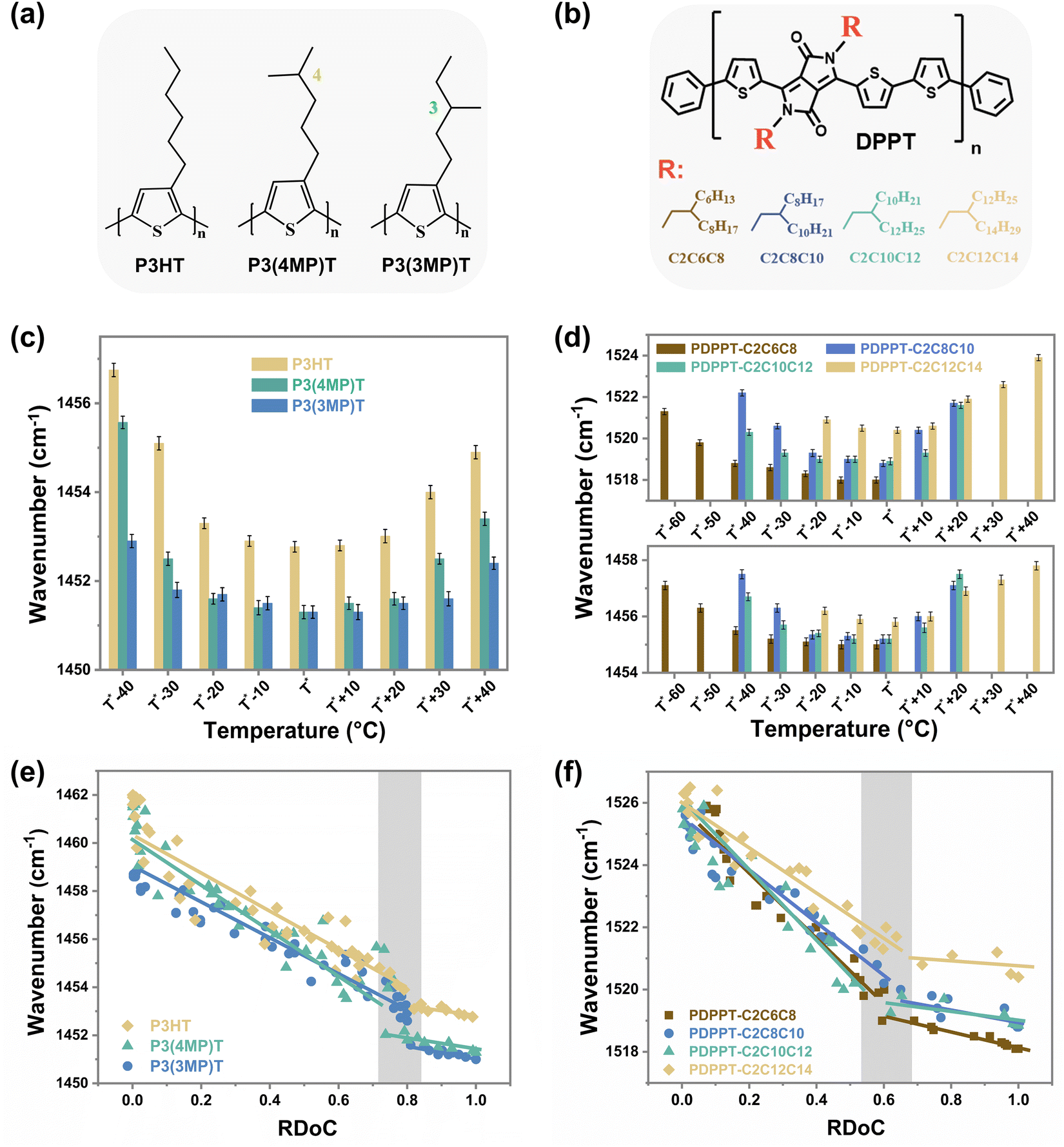 | ||
| Fig. 3 The disparity between the crystallization and the segmental order of PDPPT-based and P3AT films with different side chain structures. Chemical structures of (a) P3AT polymers and (b) PDPPT-based polymers with different side chain structures. The variations of saturated wavenumbers of CC modes of (c) P3AT polymers and (d) PDPPT-based polymers with different crystallization temperatures. The variations of wavenumbers of CC modes of (e) P3AT polymers and (f) PDPPT-based polymers with different RDoC. | ||
Correlating segmental order with segmental dynamics and electronic properties
Building on the findings discussed earlier, we can classify the segmental order of films according to their crystallinity into three temperature regions, as illustrated in Fig. 4(a). At a crystallization temperature of T*, the most ordered structure is formed with the highest crystallinity by an efficient crystallization rate. In the temperature region I (TR I, Fig. 4(a)), even at lower crystallinity levels, an ordered segmental structure is still formed through a longer crystallization time. In the temperature region II (TR II, Fig. 4(a)), the ordering of the film shows a noticeable decline with the decreasing crystallinity.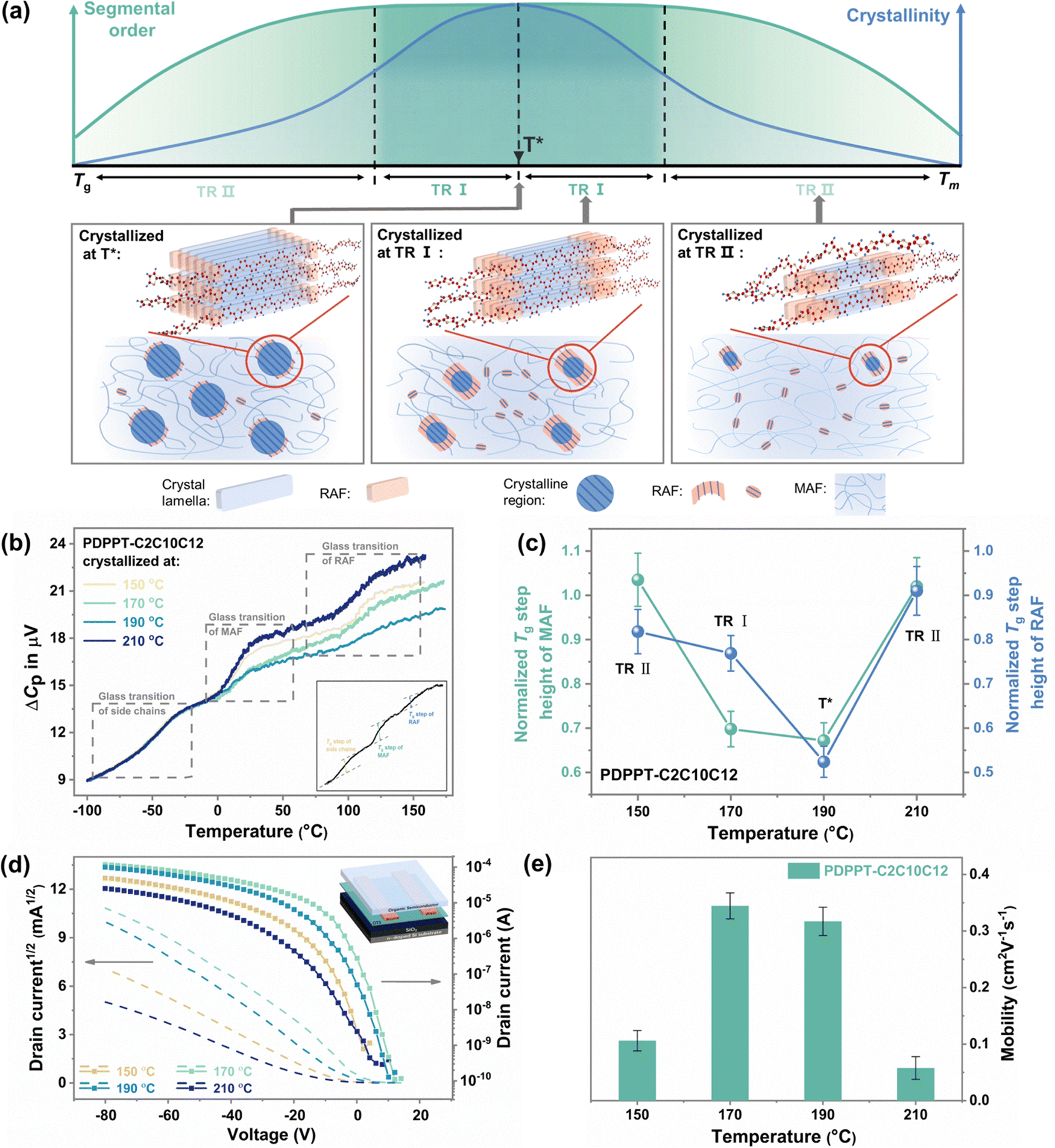 | ||
| Fig. 4 The influence of segmental order and crystallization on the chain dynamics and electrical performance. (a) Schematic of microstructure evolution in CP films when crystallized at three different temperature regions. (b) Glass transition behavior of the PDPPT-C2C10C12 film after crystallized at 150 °C, 170 °C, 190 °C and 210 °C. (c) Normalized Tg step heights of MAF and RAF in the PDPPT-C2C10C12 film after crystallizing at different temperatures. (d) Transfer characteristics for OFET devices of PDPPT-C2C10C12 annealed at different temperatures, and (e) average charge-carrier mobilities of PDPPT-C2C10C12 film calculated in saturation mode (Vd = −80 V). | ||
The segmental dynamics of CPs vary depending on the temperature region in which they are crystallized. The microstructures formed during crystallization commonly consist of a crystalline fraction and two types of amorphous phases, including mobile amorphous fractions (MAF) and rigid amorphous fractions (RAF).41–43 Commonly, chains in the crystalline region exhibit the lowest mobility and are in an ordered structure, while chains in the amorphous fractions tend to be less ordered due to their anisotropic nature. However, CP chains are highly rigid and planar, leading to a significant presence of RAF in the amorphous fractions.44 Here, we qualitatively analyze the weight fractions of MAF and RAF in PDPPT-C2C10C12 films crystallized at different temperatures. To do this, we use the heat capacity step of each amorphous fraction during the glass transition detected by alternating current (ac) chip calorimetry. As shown in Fig. 4(b) (raw data are shown in ESI,† Fig. S16), the devitrification of three different amorphous fractions, including the side chain fraction, MAF and RAF, is observed. The Tg of each fraction is similar to the values reported before.43,45,46 The weight fraction of MAF and RAF can be interpreted by the normalized step change at the glass transition. As summarized in Fig. 4(c), the normalized Tg step change of both MAF and RAF show low values at the crystallization temperature of 190 °C (T*). At a lower temperature of 170 °C (at TR I), the normalized Tg step change of RAF exhibits a significant increase, while the increment of normalized Tg step change of MAF is not pronounced. Hence, we propose that the high ordering of film at TR I is a result of the increase in the weight fraction of RAF. The low mobility of chains in RAF maintains the planar ordered structure when chains moved off the crystalline phase. At temperatures of 150 °C and 210 °C (at TR II), the normalized crystallinity decreases obviously to less than ∼0.6, and the normalized weight fraction of MAF and RAF both increase to large values, leading to a decrease in the segmental order of the film. Thus, significant difference of segmental dynamics can be observed through the controlling of crystallization.
The independent growth of RAF and MAF with the decrease of crystalline phase helps to explain the high segmental order at relatively lower crystallinity. The observed RAF may include not only anchored chains in the boundary of the crystalline fraction, but also local aggregates, semi-paracrystalline phase or tie chains with low mobility.47,48 In comparison to the traditional MAF, RAF exhibits lower mobility, higher Tg, and structural-induced higher ordering, which plays an important role in facilitating highly efficient charge transport and desirable mechanical properties.42,49,50 Hence, the existence of these amorphous chains exhibiting limited mobility could potentially play a pivotal role in the film's high segmental order and low crystalline characteristics.
The electrical performance shows a strong correlation with the segmental order rather than crystallinity. The PDPPT-C2C10C12 films were fabricated into bottom-gate, bottom-contact OFET devices (inset of Fig. 4(d)) by annealing at different temperatures after spinning coating. As shown in Fig. 4(d) and (e), the devices annealed at 150, 170, 190 and 210 °C showed the hole mobility of 0.106, 0.345, 0.317 and 0.058 cm2 V−1 s−1, respectively. Additionally, devices based on fully amorphous CP films annealed at different temperatures for 15 min also showed higher hole mobilities when annealed at 150 °C and 170 °C (T*) (ESI,† Fig. S17), indicating that crystallization at a tailored temperature range could result in sufficient crystallinity and form a favorable film morphology for efficient charge transport. These findings suggest that understanding the microstructure evolution through crystallization can be critical in optimizing device performance.
Toward predicting the temperature range that provides the best segmental structural order of CP films
Since the crystallization-induced segmental order plays an important role on the segmental dynamics and electrical performance of CP film, the prediction of TR I is of great significance. Normally, the segmental dynamics of films are too low to efficiently align together to organize ordered nucleus at low temperatures close to Tg. At high temperatures near melting temperature (Tm), the thermodynamic driving force, which reflect the free energy difference between amorphous and crystalline phases, decreases dramatically, and few nuclei are stable enough to grow. At intermediate temperatures between Tm and Tg, both homogenous and heterogenous nucleation are favorable. Therefore, it is not surprising to observe an optimal temperature for the samples to reach high crystallinity by fast kinetics. Based on these considerations, TR I generally lies somewhere near the middle of Tg and Tm. To predict the position of TR I, a segmental order temperature (Tso) was introduced as: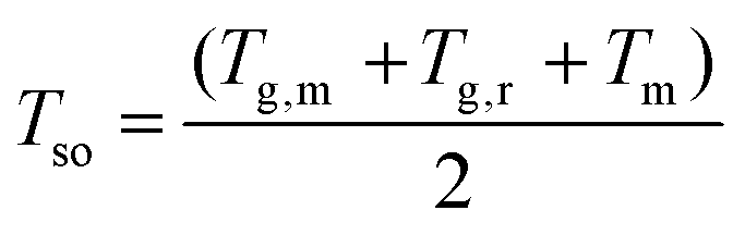 | (1) |
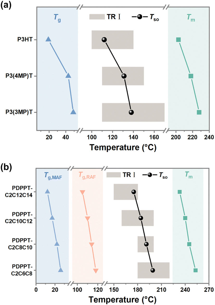 | ||
| Fig. 5 The relationship between TR I, Tg and Tm. (a) Tg and Tm, Tso and TR I of various P3ATs films. (b) Tg and Tm, Tso and TR I of various PDPPT-based films. | ||
Conclusions
Real-time characterization of segmental order and crystallization behavior of two conjugated polymer systems, namely P3ATs and PDPPT-based CPs, is performed by a novel approach combining FSC with in situ resonant micro-Raman spectroscopy. The combination of these two methods facilitates the observation of the gradual formation of segmentally ordered structures during isothermal crystallization, as well as the subsequent quantitative analysis of crystalline fraction growth during heating scans of FSC detection. The segmental order and crystallinity of the polymers increase positively with crystallization time at low rates of RDoC. However, as crystallinity increases, a clear disparity is observed between segmental order and crystalline order, as the degree of segmental order reaches a saturation plateau before maximum crystallinity is achieved. Specifically, the segmental order saturation occurred at an RDoC of approximately 80% for P3AT films and 60% for PDPPT-based films. We further investigate the influence of crystallization-induced segmental order on the segmental dynamics of samples. Ac chip calorimetric data shows that the segmental dynamics of the film correlate well with the segmental order, rather than the crystallinity. The increasing amount of RAF, including local aggregates and anchored chains at the boundary of the crystalline domain, promote the segmental order regardless of the crystallinity. Thus, the presence of these low mobility chains in the amorphous fraction is key to enhancing segmental order by a relatively lower crystallinity. In addition, electrical performance also shows a strong correlation with the segmental order rather than crystallinity. Higher charge carrier mobility can be obtained with high segmental order but lower crystallinity through the controlling of crystallization temperature. Finally, we propose a method for predicting the temperature range required to obtain a tailored structure based on Tg and Tm, which is essential for achieving desired crystallinity and segmental ordered structure.The approach presented in this study is crucial for realizing the relationship between crystallization and segmental order of CPs and helps to rationalize the reported high electronic performance at low crystallinity. The results highlight the significance of intermediate segmental dynamics in polymer chains, which are higher than those in the crystalline phase but lower than those in the mobile amorphous phase. As such, the presence of these rigid amorphous chains enhances chain alignment and provides effective interconnectivity, while also reducing the mechanical modulus and increasing mechanical ductility through the restricted growth of large crystallites. The knowledge gained from this study not only provides valuable insights into the mechanisms that govern the formation of segmental ordering structure during crystallization, but also enables the precise design and control of tailored properties and optimized optoelectronic performance of CP films.
Experimental section
Materials
Regioregular polyalkylthiophenes (P3ATs) were synthesized through a quasi-living Kumada catalyst transfer polymerization (KCTP) method.51–53 The polymers have high regularities of over 97%. The PDPPT polymers with different side-chain structures were synthesized using previously reported procedures.45,54 The detailed chemical structure of P3ATs and PDPPT-based polymers used in this paper were shown in Fig. 3(a) and (b). The molecular weight and polydispersity index of each sample were summarized in Table 1. Chlorobenzene was purchased from Sigma Aldrich and purified before use.| Polymer | M n (kg mol−1) | PDI | Regioregularity (%) |
|---|---|---|---|
| P3HT | 20.0 | 1.05 | 97 |
| P3(4MP)T | 20.9 | 1.06 | 97 |
| P3(3MP)T | 17.3 | 1.68 | 98 |
| PDPPT-C2C6C8 | 88.5 | 4.09 | |
| PDPPT-C2C8C10 | 76.6 | 3.27 | |
| PDPPT-C2C10C12 | 60.6 | 2.44 | |
| PDPPT-C2C12C14 | 61.8 | 2.97 |
Thin film preparation
A thin layer of PSS (polystyrene sulfonate) was first spin-coated on a cleaned silicon substrate with a native oxide layer as a sacrifice layer. Then, CP thin films were fabricated by spin-coating polymer solutions on PSS layer with a similar thickness of 70 ± 5 nm. Then, the thin films were cut into small pieces and dipped into the water to release the PSS layer. Tiny fragments of thin films were transferred onto the heating area of sensors by the method we illustrated before.25 To make sure the mass of each sample is similar, the sample size of each sample is controlled to just cover the heating area of the sensor. The sensors were annealed under vacuum at 80 °C for 3 hours and 20 °C for 24 hours to remove residual solvent.Stage type fast scanning calorimetry
The schematic diagram of stage type FSC is shown in ESI,† Fig. S1. The chip sensor temperature control and data acquisition (DAQ) system are similar to Tube-Dewar type UFSC developed by Zhuravlev and Schick.24,55 Ceramic housing chip sensors XEN-3939 purchased from Xensor Integration are used. Two chip sensors are placed in parallel on the silver thermal sink, which offers an identical and stable ambient temperature for both of them. There is a glass window on the surface of the chamber to allow the laser beams to pass through. Therefore, the whole chamber could be placed under the microscope of micro-Raman to integrate two approaches together. Full descriptions of stage-type FSC are shown in our previous work.32Time-temperature program for measurement
The isothermal crystallization study and Raman spectra were performed following the time-temperature program illustrated in Fig. 1. The scanning rates of 10000 K s−1 were used in this study. The sample was first heated to a temperature higher than the melt temperature and held for 0.1 s. Then, the sample was cooled to a crystallization temperature. After crystallization for a specific time, the sample was cooled back to −100 °C. Then, the Raman measurement was performed for analyzing the CC and C–C modes. At last, a measurement heating scan was performed for quantitatively analyzing the crystallization in the previous annealing. The endothermic peak in the measurement scan was integrated and interpreted using the Avrami crystallization model.
In situ resonant Raman spectroscopic characterization
A Renishaw inVia-Reflex Raman microscopy was used to perform Raman measurements on CP films. The excitation wavelength is 488 nm for the resonant Raman measurements. The excitation power used for the 488 nm laser is an Argon-ion laser. All the measurements were done in the thermal stage under a nitrogen environment to reduce degradation and at −100 °C to prevent any temperature jump under laser irradiation. The spectra were obtained with an acquisition time of 1 s and 10 data accumulations.Alternating current (ac) chip calorimeter
Ac chip calorimetry was used to detect and quantify the glass transition in different samples. The XI-392 sensor from Xensor Integration with a heated area of 100 μm × 100 μm was used. To minimize the blank signal differences between reference and sample sensors, the centre areas of sensors were all first cleaned by chloroform and then annealed at 453 K in a vacuum for 1 h before the sample loading process. A heating rate of 1 °C min−1 and a frequency of 10 Hz was used to probe the glass transition behavior of samples. Samples were first crystallized at different temperatures followed by the time-temperature program illustrate in Fig. 1, and then the glass transitions were detected by ac chip calorimetry through heating from −100 °C to 180 °C. All measurements were performed under a dry nitrogen atmosphere at ambient pressure. The amplitude of the complex differential voltage as a function of measuring temperature was obtained. The step of the differential voltage relates to the change of the heat capacity during the glass transition. The value of glass transition temperature (Tg) is defined as the half-step temperature of the amplitude. Since the side chains of DPP-based samples used in this experiment are fully amorphous due to the branched structure, we can normalize the step change at the glass transitions of MAF and RAF by one of the side chains in each sample, as shown in the inset of Fig. 4(b). Finally, the weight fraction of MAF and RAF can be interpreted by the normalized step change at the glass transition.Organic field-effect transistor (OFET) fabrication and electrical characterization
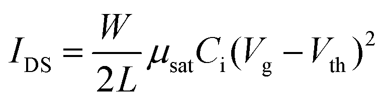
OFET devices were fabricated with bottom-gate, bottom-contact configuration. 50 nm Au source and drain electrodes on OTS-treated 300 nm SiO2/Si substrate were deposited by Temescal FC2000 E-beam evaporator. The channel length (L) and width (W) are 200 μm and 4 mm, respectively. The capacitance of dielectric layer is 11.5 nF cm−2. The semiconducting polymers were dissolved in chlorobenzene (10 mg mL−1) and spin-coated into films at around 70 nm. OFET electrical characteristics were measured using a Keithley 4200 under an ambient environment. The charge carrier mobility (μsat) and threshold voltage (Vth) were calculated by fitting the following equation:where W is the channel width, L are the channel length, and Ci is the capacitance per unit area of the dielectric layer.
Author contributions
S. L. and J. X. conceived and coordinated the work. G. X. and D. Z. developed the integrated equipment. S. L. and Y. L. performed all calorimetric and Raman spectroscopic measurements. Z. C., S. Z. and X. G. synthesis P3AT polymers. M. U. O. and S. R.-G. synthesis PDPPT-based polymers. N. L. and S. W. performed electrical characterization. S. L. and J. X. wrote the paper. All authors contributed to the editing of the paper.Conflicts of interest
The authors declare no conflict of interest.Acknowledgements
S. L., Y. L., G. X. and D. Z. are grateful for the support from the National Natural Science Foundation of China (no. 21790345, 22173046, 51673094), Fundamental research funds for the central university (grant no. 020514380274), National Key Research and Development Program of China (grant no. 2020YFA0711504), Shenzhen Science and Technology Innovation Committee (JCY 20200109150656717, JSGG20210629144802007, and JSGG20200103094001790). J. X. acknowledges the support from the University of Chicago on the project of Controlled Organization of Polymeric Solids (PRJ1007197). Z. C., S. Z. and X. G. thanks U.S. Department of Energy, Office of Science, Office of Basic Energy Science under the award DE-SC0022050. Part of the research was conducted at the Center for Nanoscale Materials, a U.S. Department of Energy Office of Science User Facility, which is supported by the U.S. DOE, Office of Basic Energy Sciences, under contract no. DE-AC02-06CH11357. S. R.-G. thank the Natural Science and Engineering Research Council of Canada (NSERC) for financial support through a Discovery Grants (RGPIN-2022-04428). M. U. O. thanks NSERC for financial support through a Canadian Graduate Scholarship (CGSD3-534870-19).References
- S. Khan, L. Lorenzelli and R. S. Dahiya, IEEE Sens. J., 2015, 15, 3164–3185 Search PubMed.
- J. S. Chang, A. F. Facchetti and R. Reuss, IEEE J. Emerg. Sel. Top. Circuits Syst., 2017, 7, 7–26 Search PubMed.
- J. Oliveira, R. Brito-Pereira, B. F. Gonçalves, I. Etxebarria and S. Lanceros-Mendez, Org. Electron., 2019, 66, 216–226 CrossRef CAS.
- S. Wang, J. Y. Oh, J. Xu, H. Tran and Z. Bao, Acc. Chem. Res., 2018, 51, 1033–1045 CrossRef CAS.
- S. H. Wang, J. Xu, W. C. Wang, G. J. N. Wang, R. Rastak, F. Molina-Lopez, J. W. Chung, S. M. Niu, V. R. Feig, J. Lopez, T. Lei, S. K. Kwon, Y. Kim, A. M. Foudeh, A. Ehrlich, A. Gasperini, Y. Yun, B. Murmann, J. B. H. Tok and Z. A. Bao, Nature, 2018, 555, 83–88 CrossRef CAS.
- Z. Peng, L. Ye and H. Ade, Mater. Horizons, 2022, 9, 577–606 RSC.
- R. Noriega, J. Rivnay, K. Vandewal, F. P. Koch, N. Stingelin, P. Smith, M. F. Toney and A. Salleo, Nat. Mater., 2013, 12, 1038–1044 CrossRef CAS PubMed.
- Y. Liu, Q. Zhang, J. Guan, J. Xue, X. Yu, F. Wu, W. Ma and Y. Han, ACS Appl. Mater. Inter., 2022, 14, 44685–44696 CrossRef CAS PubMed.
- R. Noriega, J. Rivnay, K. Vandewal, F. P. V. Koch, N. Stingelin, P. Smith, M. F. Toney and A. Salleo, Nat. Mater., 2013, 12, 1038–1044 CrossRef CAS PubMed.
- K. Gu and Y.-L. Loo, J. Polym. Sci., Part B: Polym. Phys., 2019, 57, 1559–1571 CrossRef CAS.
- J. Xu, S. Wang, G.-J. N. Wang, C. Zhu, S. Luo, L. Jin, X. Gu, S. Chen, V. R. Feig, J. W. F. To, S. Rondeau-Gagne, J. Park, B. C. Schroeder, C. Lu, J. Y. Oh, Y. Wang, Y.-H. Kim, H. Yan, R. Sinclair, D. Zhou, G. Xue, B. Murmann, C. Linder, W. Cai, J. B. H. Tok, J. W. Chung and Z. Bao, Science, 2017, 355, 59–64 CrossRef CAS.
- J. Xu, H.-C. Wu, C. Zhu, A. Ehrlich, L. Shaw, M. Nikolka, S. Wang, F. Molina-Lopez, X. Gu, S. Luo, D. Zhou, Y.-H. Kim, G.-J. N. Wang, K. Gu, V. R. Feig, S. Chen, Y. Kim, T. Katsumata, Y.-Q. Zheng, H. Yan, J. W. Chung, J. Lopez, B. Murmann and Z. Bao, Nat. Mater., 2019, 18, 594–601 CrossRef CAS PubMed.
- X. Pan, J. M. Bjuggren, M. Jevric, W. L. Tan, C. R. McNeill and M. R. Andersson, Chem. Mater., 2022, 34, 5103–5115 CrossRef CAS.
- D. Venkateshvaran, M. Nikolka, A. Sadhanala, V. Lemaur, M. Zelazny, M. Kepa, M. Hurhangee, A. J. Kronemeijer, V. Pecunia, I. Nasrallah, I. Romanov, K. Broch, I. McCulloch, D. Emin, Y. Olivier, J. Cornil, D. Beljonne and H. Sirringhaus, Nature, 2014, 515, 384–388 CrossRef CAS PubMed.
- B. Lin, X. Zhou, H. Zhao, J. Yuan, K. Zhou, K. Chen, H. Wu, R. Guo, M. A. Scheel, A. Chumakov, S. V. Roth, Y. Mao, L. Wang, Z. Tang, P. Mueller-Buschbaum and W. Ma, Energy Environ. Sci., 2020, 13, 2467–2479 RSC.
- O. K. Tsui, Y. J. Wang, F. K. Lee, C.-H. Lam and Z. Yang, Macromolecules, 2008, 41, 1465–1468 CrossRef CAS.
- P. Damman, S. Gabriele, S. Coppée, S. Desprez, D. Villers, T. Vilmin, E. Raphaël, M. Hamieh, S. Al Akhrass and G. Reiter, Phys. Rev. Lett., 2007, 99, 036101 CrossRef PubMed.
- A. Salleo, R. J. Kline, D. M. DeLongchamp and M. L. Chabinyc, Adv. Mater., 2010, 22, 3812–3838 CrossRef CAS PubMed.
- H. N. Tsao and K. Müllen, Chem. Soc. Rev., 2010, 39, 2372–2386 RSC.
- C. Wang, F. Moro, S. Ni, Q. Zhang, G. Pan, J. Yang, F. Zhang, I. A. Buyanova, W. M. Chen and X. Liu, Nano Energy, 2020, 104677 CrossRef CAS.
- S. Cho, K. Lee, J. Yuen, G. Wang, D. Moses, A. J. Heeger, M. Surin and R. Lazzaroni, J. Appl. Phys., 2006, 100, 114503 CrossRef.
- C. M. Fu, K. S. Jeng, Y. H. Li, Y. C. Hsu, M. H. Chi, W. B. Jian and J. T. Chen, Macromol. Chem. Phys., 2015, 216, 59–68 CrossRef CAS.
- L. H. Jimison, A. Salleo, M. L. Chabinyc, D. P. Bernstein and M. F. Toney, Phys. Rev. B: Condens. Matter Mater. Phys., 2008, 78, 125319 CrossRef.
- E. Zhuravlev and C. Schick, Thermochim. Acta, 2010, 505, 1–13 CrossRef CAS.
- S. C. Luo, X. Kui, E. R. Xin, X. L. Wang, G. Xue, C. Schick, W. B. Hu, E. Zhuravlev and D. S. Zhou, Macromolecules, 2018, 51, 5209–5218 CrossRef CAS.
- S. C. Luo, N. Li, S. Zhang, C. Zhang, T. F. Qu, M. U. Ocheje, G. Xue, X. D. Gu, S. Rondeau-Gagne, W. B. Hu, S. H. Wang, C. Teng, D. S. Zhou and J. Xu, Chem. Mater., 2021, 33, 1637–1647 CrossRef CAS.
- S. Wood, J. R. Hollis and J.-S. Kim, J. Phys. D: Appl. Phys., 2017, 50, 073001 CrossRef.
- W. C. Tsoi, D. T. James, J. S. Kim, P. G. Nicholson, C. E. Murphy, D. D. Bradley, J. Nelson and J. S. Kim, J. Am. Chem. Soc., 2011, 133, 9834–9843 CrossRef CAS PubMed.
- S. Wood, J. Wade, M. Shahid, E. Collado-Fregoso, D. D. Bradley, J. R. Durrant, M. Heeney and J.-S. Kim, Energy Environ. Sci., 2015, 8, 3222–3232 RSC.
- Z. Fei, P. Boufflet, S. Wood, J. Wade, J. Moriarty, E. Gann, E. L. Ratcliff, C. R. McNeill, H. Sirringhaus, J.-S. Kim and M. Heeney, J. Am. Chem. Soc., 2015, 137, 6866–6879 CrossRef CAS PubMed.
- W. C. Tsoi, W. Zhang, J. Razzell Hollis, M. Suh, M. Heeney, I. McCulloch and J.-S. Kim, Appl. Phys. Lett., 2013, 102, 173302 CrossRef.
- L. Wei, J. Jiang, M. Shan, W. Chen, Y. Deng, G. Xue and D. Zhou, Rev. Sci. Instrum., 2014, 85, 074901 CrossRef PubMed.
- T. Qu, Y. Li, L. Li, C. Zhang, X. Wang, W. Chen, G. Xue, E. Zhuravlev, S. Luo and D. Zhou, Macromolecules, 2023, 56, 6407–6418 CrossRef CAS.
- S. H. Yu, K. H. Park, Y.-H. Kim, D. S. Chung and S.-K. Kwon, Macromolecules, 2017, 50, 4227–4234 CrossRef CAS.
- S. Zhang, Y.-H. Cheng, L. Galuska, A. Roy, M. Lorenz, B. Chen, S. Luo, Y.-T. Li, C.-C. Hung, Z. Qian, P. B. J. St. Onge, G. T. Mason, L. Cowen, D. Zhou, S. I. Nazarenko, R. F. Storey, B. C. Schroeder, S. Rondeau-Gagné, Y.-C. Chiu and X. Gu, Adv. Funct. Mater., 2020, 30, 2000663 CrossRef CAS.
- S. Zhang, M. U. Ocheje, S. Luo, D. Ehlenberg, B. Appleby, D. Weller, D. Zhou, S. Rondeau-Gagné and X. Gu, Macromol. Rapid Commun., 2018, 39, 1800092 CrossRef.
- S. Zhang, L. A. Galuska and X. Gu, J. Polym. Sci., 2022, 60, 1108–1129 CrossRef CAS.
- Y. Yang, Z. Liu, G. Zhang, X. Zhang and D. Zhang, Adv. Mater., 2019, 31, 1903104 CrossRef CAS PubMed.
- Z. Cao, L. Galuska, Z. Qian, S. Zhang, L. Huang, N. Prine, T. Li, Y. He, K. Hong and X. Gu, Polym. Chem., 2020, 11, 517–526 RSC.
- Z. Y. Qian, S. C. Luo, T. F. Qu, L. A. Galuska, S. Zhang, Z. Q. Cao, S. Dhakal, Y. J. He, K. L. Hong, D. S. Zhou and X. D. Gu, J. Mater. Res., 2021, 36, 191–202 CrossRef CAS.
- B. S. Beckingham, V. Ho and R. A. Segalman, ACS Macro Lett., 2014, 3, 684–688 CrossRef CAS PubMed.
- A. Sangroniz, A. Chaos, M. Iriarte, J. del Rio, J. R. Sarasua and A. Etxeberria, Macromolecules, 2018, 51, 3923–3931 CrossRef CAS.
- S. C. Luo, T. Y. Wang, M. U. Ocheje, S. Zhang, J. Xu, Z. Y. Qian, X. D. Gu, G. Xue, S. Rondeau-Gagne, J. Jiang, W. B. Hu, E. Zhuravlev and D. S. Zhou, Macromolecules, 2020, 53, 4480–4489 CrossRef CAS.
- R. Remy, S. J. Wei, L. M. Campos and M. E. Mackay, ACS Macro Lett., 2015, 4, 1051–1055 CrossRef CAS PubMed.
- S. Zhang, A. Alesadi, M. Selivanova, Z. Cao, Z. Qian, S. Luo, L. Galuska, C. Teh, M. U. Ocheje, G. T. Mason, P. B. J. Onge, D. Zhou, S. Rondeau-Gagné, W. Xia and X. Gu, Adv. Funct. Mater., 2020, 30, 2002221 CrossRef CAS.
- Z. Y. Qian, Z. Q. Cao, L. Galuska, S. Zhang, J. Xu and X. D. Gu, Macromol. Chem. Phys., 2019, 220, 1900062 CrossRef.
- E. Lim, A. M. Glaudell, R. Miller and M. L. Chabinyc, Adv. Electron. Mater., 2019, 5, 1800915 CrossRef.
- S. Marina, E. Gutierrez-Fernandez, J. Gutierrez, M. Gobbi, N. Ramos, E. Solano, J. Rech, W. You, L. Hueso and A. Tercjak, Mater. Horizons, 2022, 9, 1196–1206 RSC.
- E. Zuza, J. M. Ugartemendia, A. Lopez, E. Meaurio, A. Lejardi and J. R. Sarasua, Polymer, 2008, 49, 4427–4432 CrossRef CAS.
- J. Martin, N. Stingelin and D. Cangialosi, J. Phys. Chem. Lett., 2018, 9, 990–995 CrossRef CAS PubMed.
- S. Tamba, S. Tanaka, Y. Okubo, H. Meguro, S. Okamoto and A. Mori, Chem. Lett., 2011, 40, 398–399 CrossRef CAS.
- S. Tanaka, S. Tamba, D. Tanaka, A. Sugie and A. Mori, J. Am. Chem. Soc., 2011, 133, 16734–16737 CrossRef CAS PubMed.
- S. Tamba, K. Shono, A. Sugie and A. Mori, J. Am. Chem. Soc., 2011, 133, 9700–9703 CrossRef CAS PubMed.
- S. Zhang, M. U. Ocheje, L. F. Huang, L. Galuska, Z. Q. Cao, S. C. Luo, Y.-H. Cheng, D. Ehlenberg, R. B. Goodman, D. S. Zhou, Y. Liu, Y.-C. Chiu, J. D. Azoulay, S. Rondeau-Gagné and X. D. Gu, Adv. Electron. Mater., 2019, 5, 1800899 CrossRef.
- E. Zhuravlev and C. Schick, Thermochim. Acta, 2010, 505, 14–21 CrossRef CAS.
Footnote |
| † Electronic supplementary information (ESI) available. See DOI: https://doi.org/10.1039/d3mh00956d |
| This journal is © The Royal Society of Chemistry 2024 |