
 Open Access Article
 This Open Access Article is licensed under a Creative Commons Attribution-Non Commercial 3.0 Unported Licence
DNA nanostar structures with tunable auxetic properties†
Yancheng
Du
,
Ruixin
Li
,
Anirudh S.
Madhvacharyula
,
Alexander A.
Swett
and
Jong Hyun
Choi
 *
*
School of Mechanical Engineering, Purdue University, West Lafayette, Indiana 47907, USA. E-mail: jchoi@purdue.edu
First published on 9th April 2024
Abstract
Auxetic structures are unique with a negative Poisson's ratio. Unlike regular materials, they respond to external loading with simultaneous expansion or compression in all directions, rendering powerful properties advantageous in diverse applications from manufacturing to space engineering. The auxetic behaviors are determined by structural design and architecture. Such structures have been discovered in natural crystals and demonstrated synthetically with bulk materials. Recent development of DNA-based structures has pushed the unit cell size to the nanometer scale. DNA nanotechnology utilizes sequence complementarity between nucleotides. By combining sequence designs with programmable self-assembly, it is possible to construct complex structures with nanoscale accuracy and to perform dynamic reconfigurations. Herein, we report a novel design of auxetic nanostars with sliding behaviors using DNA origami. Our proposed structure, inspired by an Islamic pattern, demonstrates a unit cell with two distinct reconfigurations by programming directed sliding mechanisms. Compared to previous metamaterials, the DNA nanostars show an architecture with tunable auxetic properties for the first time. We envision that this strategy may form the basis of novel metastructures with adaptability and open new possibilities in bioengineering.
Design, System, ApplicationAuxetic metamaterials are unique structures with a negative Poisson's ratio. Their mechanical behaviors come from rational structural designs and have been demonstrated across various lengthscales. Recent advances in DNA nanotechnology have shown the potential to construct such materials at the nanoscale. However, most metastructures deform as designed with a predetermined Poisson's ratio. Here, we introduce an auxetic design with tunable behaviors by exploiting the programmability of DNA self-assembly. A unit cell is designed with three nanostars, where adjacent nanostars can slide against each other in different directions. We show that auxetic reconfigurations of DNA origami are realized by strand displacement and repositioning and that two combinations of sliding behaviors give rise to two distinct negative Poisson's ratios. We envision that this work will open new possibilities for nanoscale metamaterials with tunable properties which may be programmed for diverse applications. |
Introduction
Auxetic metamaterials are synthetic architectures that respond to external loading in a unique manner. Regular materials under compressive (or extensive) forces will expand (or contract) in orthogonal directions. In contrast, auxetic structures deform simultaneously in all directions. The Poisson's ratio measures such a property which describes deformation behaviors quantitatively: | (1) |
Most metamaterials have periodic cellular structures and their auxetic behaviors arise from unit cell designs, which will deform in unison upon external forces. The unit cells range over various length scales. For example, naturally occurring crystals such as α-cristobalite and cubic metals demonstrate auxetic properties with unit cells of sub-nanometer sizes.10–12 Conventional auxetics have been manufactured with metals,13 polymers,14 and other materials15 at larger scales from microns to centimeters. There is a lack of studies on auxetic metamaterials at the nanoscale.16 Recently, Li et al. bridged this gap in the lengthscale.17,18 In their studies, nanoscale auxetic units were constructed using DNA origami exploiting sequence complementarity of DNA molecules. DNA self-assembly has been developed as a powerful bottom-up strategy with excellent programmability and precision19 and demonstrated for complex architectures,20–25 reconfigurable designs,26–29 and dynamic processes.30–33 Their origami architectures were designed with ‘jack’ edges, whose lengths were adjusted by two-step DNA reactions for global structural transformations. The ‘chemical deformation’ resulted in negative Poisson's ratio (NPR) behaviors.
While the work opened new opportunities for nanoscale metamaterials, the structures were limited in that their auxetic deformations were pre-determined and could not change. In fact, this behavior is also similar for most metastructures at other lengthscales. Herein, we ask if it is possible to program distinct pathways of NPR reconfigurations. To achieve such tunable auxetic properties, we propose a novel design of origami-based DNA nanostars that can reconfigure in different directions upon external loading via chemical deformations. The DNA architecture was inspired by one of the Islamic pattern designs that have been used in arts and buildings. Our DNA origami design consists of 3 nanostars that can slide against each other in two distinct directions, thus resulting in two NPR values. We have investigated their structures and behaviors with coarse-grained molecular dynamics (MD) simulations and atomic force microscopy (AFM). This work opens a new horizon towards smart materials with adaptive mechanical properties for applications involving complex and ever-changing environments.
Experimental section
Computer-aided origami design
The design of the wireframe DNA origami was conducted using cadnano2.34,35 The edges were designed as four double-stranded (ds) bundles with staples routed around to increase rigidity. The vertices were designed with single-stranded (ss) DNA to allow flexibility in turning angles. In our design, regular right-handed B-form DNA was assumed to have an increase on the axis of 0.332 nm per base pair (bp). Positional staples on edges used for performing sliding actions contained binding domains of 10 nucleotides (nt). For strand displacement reactions, 8 nt ss-toeholds were added to one end of the strands. Detailed sequence information is presented in Tables S1 and S2.†DNA origami synthesis
All DNA origami structures were prepared at a concentration of 5 nM scaffold DNA with 4× staple strands in 1× TAE buffer solution (containing 40 mM trisaminomethane, 20 mM acetic acid, and 1 mM ethylenediaminetetraacetic acid (EDTA) disodium salt with pH ∼ 8). A final concentration of 6 mM Mg2+ was provided. The mixture was put in a BIO-RAD S1000 thermal cycler under a custom-designed thermal cycle. The sample was heated to 75 °C for 18 minutes and then cooled down at a ramping rate of −0.1 °C/15 min until it reached 25 °C. The solution was then stored at 4 °C before further experiments.Sliding experiment
Toehold-mediated strand displacement was used for origami sliding motions. The sliding was performed in two steps: (1) removal of previous positional staples and (2) insertion of new positional staples. The first step was carried out by adding 50× releaser strands and incubating the mixture in the thermal cycler at 40 °C for 12 hours before cooling down to 25 °C at a rate of −0.1 °C/6 seconds. Then the mixture was purified by using centrifugal filters (Amicon) to remove excess strands. For centrifugation, approximately 55 μL of the DNA origami mixture was added to the filter and additional TAE buffer with 6 mM Mg2+ was added to reach a final volume of 500 μL. Then the mixture was centrifuged at 5000 rpm for 3 minutes and the solution remaining in the filter was retrieved. After the first step, the origami structures were released to an undefined position. In the second step, new staples defining the relative positions of the three-stars were added at a 10-fold higher concentration. The mixture was subsequently reannealed in the thermal cycler at 40 °C for 12 hours and then cooled down to 25 °C at a rate of −0.1 °C/6 seconds. The sample was then stored at 4 °C for further measurements or experiments.Coarse-grained MD simulations
We performed MD simulations to evaluate the DNA design and verify structural integrity. In the coarse-grained MD model, pseudo-atoms are used to represent a group of atoms in order to reduce the complexity of calculations. For a predetermined simulation time, particles representing the structures follow designated interactions to demonstrate the development of the system dynamically. In our study, the oxDNA platform36,37 was used for computing the equilibrium conformations of the origami structures. In the oxDNA model, DNA strands are represented by a string of rigid nucleotides, where multiple interactions are taken into consideration including sugar–phosphate backbone connectivity, excluded volume, hydrogen bonding, etc. To perform the computation, we used the designed static structures from caDNAno and converted them into topology and configuration files using real sequence information as initial conformations in oxDNA. The environmental parameters were set based on the experimental conditions. The temperature was the same as in the experiments, while the magnesium concentration of [Mg2+] = 6 mM was replaced with [Na+] = 0.5 M due to limited options in the computational platform. The initial configurations of DNA origami were first relaxed by setting the phosphate backbone connection 10 times stronger to pull the edges to their places. Then, a threshold of 3% relative fluctuations was set to start the second stage of simulations, where the structures were computed for more than 106 steps to reach an equilibrium state for observation. For each conformation, the simulation took about two days. The resulting structures were visualized with oxView38 and the quantitative measurements were performed on the platform.AFM imaging
The planar origami structures were characterized by AFM in air. The samples prepared were deposited on mica surfaces for measurements. The target sample was diluted to ∼0.5 nM in 1× TAE buffer with 6 mM Mg2+. A 10 μL aliquot of the diluted sample was added onto a freshly peeled mica surface and deposited for 5 minutes. Then the liquid was blown away with compressed air. Approximately 80 μL of DI water was added to the mica surface afterward and immediately blown away to avoid salt accumulation. AFM imaging was carried out with a Bruker Dimension Icon AFM using ScanAsyst-Air probes in the Peak-Force tapping mode. We followed the same procedure for sample preparation and measurement as previously described.17 The lengths of edges and the angles at vertices were measured and matched with our designs.Results and discussion
Design of architected metastructures from DNA
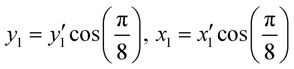
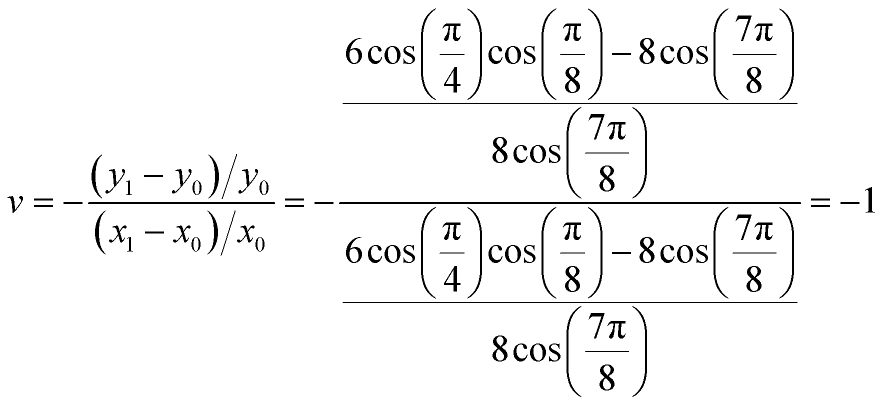
Fig. 1a shows the proposed auxetic design inspired by an Islamic geometric pattern. The Islamic pattern consists of periodic 2D arrays of large and small stars shown in black and red. The unit cell includes one small and two large stars which can slide along each other's edges as depicted in Fig. 1b. Upon loading on horizontal directions, the sliding mechanism results in auxetic reconfigurations globally.39 This Islamic pattern design allows only one reconfiguration due to the limitations on sliding directions. By modifying the structure, we propose a new design which enables multiple reconfigurations with a single structure. To model the system, we simplified the geometric pattern to a design of sliding 4-point stars with identical sizes as illustrated in Fig. 1c and d. The angles at four vertices of each star are designed to be π/4. Sliding of neighboring black stars along the edges of the red stars simultaneously in horizontal directions will result in contraction of the structure both horizontally and vertically (Fig. 1c). Note that the shrinkage in x and y directions will not be equal. By calculating the displacements in both directions, we can find the Poisson's ratio: | (2) |
 | (3) |
 | (4) |
 | ||
| Fig. 1 Schematics of the Islamic pattern and the auxetic design studied in this work. (a) Periodic 2D cellular structure of the Islamic pattern. The large (black) stars slide along the edges of both large and small (red) stars, resulting in a global auxetic behavior. (b) Unit cell of the Islamic pattern with two large stars and one small star. (c) and (d) A simplified design that consists of 4-point stars with identical edge lengths of ∼43.2 nm and angles of π/4. Horizontal sliding in unison between neighboring stars will lead to contraction in both horizontal and vertical directions. This auxetic reconfiguration leads to a negative Poisson's ratio of ν = −0.414. (d) If the adjacent stars move in different directions (e.g., one vertically and the other horizontally), the structure will demonstrate auxetic properties with ν = −1 via global rotation. By programming the sliding directions, two distinct auxetic behaviors can be demonstrated and structural mechanics may be tuned accordingly. (e) and (f) Unit cell that consists of two black stars and one red star. (e) The horizontal movements of the left and right black stars are named routes 1 and 3, respectively, resembling the structural transformation depicted in (c). (f) Vertical sliding of the left black star is termed route 2. Simultaneous route 2 and 3 motions represent a centrosymmetric rotation illustrated in (d). Note that vertical sliding in both stars will be redundant due to symmetry. | ||
We further simplified the design into a unit cell of three (2 black and 1 red) stars which can be constructed by DNA origami (Fig. 1e and f). Each edge of the stars is designed to have a length of approximately 43 nm long and the vertices have angles of π/4. These design parameters were later confirmed by measurements from oxDNA simulations and AFM imaging. Three sliding routes are made available for each unit cell. The horizontal sliding of the left black star is named route 1, while its vertical movement is termed route 2. Route 3 represents the horizontal sliding of the right black star. Note that the vertical sliding of the right black star is omitted due to symmetry. By programming the sliding behaviors, we can generate two combinations (routes 1 and 3 or routes 2 and 3) between the routes, which will give rise to two distinct auxetic properties. In a periodic cellular structure, the distinct Poisson's ratios indicate the difference in mechanical properties.
In this work, a unit cell of the structure capable of the sliding behaviors is demonstrated with a wireframe DNA origami method. This strategy uses edges and multi-arm joints to represent geometric patterns.40,41 In wireframe origami, edges are composed of dsDNA bundles for structural integrity and are connected by ssDNA at joints for flexibility. This method is efficient for material use and allows for designing larger structures with a limited number of nucleotides.42 To enhance the stiffness of the edges of the stars, we followed the principles previously described by Li et al.17 They demonstrated that the edge thickness t must be sufficiently large for a given length L and ss-joints at vertices must experience a certain level of tension (termed joint stretch η) in order to avoid significant flexure or distortion during reconfiguration. In our design, each star has eight outer edges. The edges consist of four duplex bundles (t/L ≈ 0.1) with 130 bp in length (approximately 43.2 nm), and joints are designed to have a stretch level of η ≈ 55% to meet the design requirements. In addition, the edges are designed in a honeycomb arrangement to avoid internal strains in the structure as shown in Fig. 2(a). Here, the long blue arrows represent the routing of scaffold sequences, and the short gray lines denote staple strands. A three-dimensional molecular model from oxDNA is also shown in Fig. S1.† Given the design parameters of our proposed structure, single origami may not provide enough nucleotides. Therefore, we adopted a double scaffold strategy developed by Dietz and coworkers43 who used multiple orthogonal scaffolds with minimal interferences for larger origami structures. Fig. 2(c)–(e) illustrate the routing of our origami design, where two kinds of scaffolds are differentiated by colors: the 9072 nt scaffold (named 9k scaffold for simplicity) provided by the Dietz group is shown in blue color and the commercially purchased 8064 nt scaffold (8k scaffold) is shown in orange color. The three-star structure is composed in a manner that each scaffold winds into one and a half stars, and the two scaffolds are connected by connecting staples to form the complete three stars. It is worth noting that the left one and a half stars in blue have a one-way connection given the linearity of the 9k scaffold, while a two-way connection is used for the right one and a half stars in orange as the 8k scaffold is circular. To differentiate between the left and right stars, a ss-loop of the scaffold is designed on the top of the right star.
 | ||
| Fig. 2 Unit cell design of three 4-point stars and experiment results with wireframe DNA origami. (a) Schematic of the side view of arrangements of dsDNA bundles of an edge. Each edge consists of four bundles, and they are arranged in a honeycomb, where their locations are indicated with the blue color. (b) Schematic of the front view of an edge segment. Each edge has four dsDNA bundles represented by four blue lines. They are connected by grey staple strands that go across different bundles to hold structural integrity. Routing of (c) 9k and (d) 8k scaffold strands. A tail of a free 8k-scaffold loop is used for distinguishing between left and right halves. (e) Routing of the fully connected three stars. (f)–(h) AFM images of wireframe DNA origami. (f) Assembled half structure from the 9k scaffold and staple strands. (g) Origami half structure with the 8k scaffold and staple strands. (h) Fully assembled three stars using both 9k and 8k scaffolds. A tail of a free 8k-scaffold loop is observed on the right star in (g) and (h). The scale bars shown are 50 nm. | ||
AFM imaging characterized the assembled DNA units. The structures from a single scaffold (e.g., 9k or 8k strands) are tested initially with a scaffold concentration of 5 nM in 1× TAE buffer with 6 mM Mg2+. Both scaffolds formed half structures as designed; the 9k scaffold shapes the left star and half of the middle star (Fig. 2(f)), while the 8k scaffold forms the right star and the other half of the middle star with a small loop at the top of the right star (Fig. 2(g)). Finally, a whole structure assembled from both scaffolds is shown in Fig. 2(h), which has an overall yield of nearly 70%. Note that the right and left stars are connected with the middle star by unpaired segments of the scaffolds as indicated by 3 lines (one in blue and two in orange) in Fig. 2(e). However, the relative positions between the stars are not determined (i.e., undefined position). Their locations are close to each other but random due to the deposition on mica surfaces – positional linker strands will determine the exact positions between the stars (vide infra). The structures are also examined with agarose gel electrophoresis. As shown in Fig. S2,† the half structures with the 8k scaffold or the 9k scaffold as well as the full three-star structures all have clear bands in the gel where the 8k-structure moves the fastest and the complete three stars were the slowest corresponding to their molecular weights.
Demonstration of auxetic sliding behaviors
With well-built structures, we designed sliding behaviors of the auxetic stars via toehold-mediated strand displacement as illustrated in Fig. 3. For each route, the three stars are arranged to start with an undefined position, where no binding is provided to determine relative positions between stars (state (i)). On one of two edges sliding against each other, three locations are modified with a 10 nt extension as binding entities (as shown in edge 1). The binding entities are chosen to provide strong associations to ensure correct positions as well as minimize the detachment between the edges. The three locations are separated by 63 bp, corresponding to a sliding distance of ∼20.9 nm between adjacent positions. Initially, the binding strands on the opposite edge (edge 2) are not provided, thus the stars remain in an undefined position as shown as state (i) in Fig. 3(b). Then, each route can be programmed to take three positions to guide the sliding behaviors. To initiate the sliding, staples on edge 2 with toeholds are replaced with new staples (P1 staples in green color) via strand displacement. This allows the stars to initially bind to each other at the opposite vertices (position 1, state (ii)). Next, the binding sequences (shown in green) can be replaced with new sets of linker strands via toehold mediated strand displacement to direct the edges to overlap halfway where the stars slide more into each other (position 2, state (iii)). The binding staples for position 2 are shown in red color. Finally, with the same strand displacement mechanism, the edges can be programmed to slide to fully overlap with each other resulting in a configuration of position 3 (state (iv)). The staple designs for position 3 are shown in purple color. With the strand displacement mechanism used, this process may also be reversed to direct the stars to move back from position 3 to position 2 and then to position 1. | ||
| Fig. 3 Illustration of the sliding mechanism. (a) Two opposite edges (edges 1 and 2) on two stars sliding against each other are shown in blue and orange colors starting from an undefined conformation (i.e., edges are not associated). For sliding, staples on edge 2 are replaced via a strand displacement mechanism (see the text for details). Initially, a set of staples on edge 2 are replaced with P1 staples (shown in green), guiding the edges to position 1 (state (i) → state (ii)). By sequentially replacing the staples with P2 (red) and P3 (purple) staples, the edges can slide to positions 2 and 3 (state (iii) and state (iv), respectively). This process may be reversed by replacing the positional staples in an opposite order. (b) Staple design for the edges at an undefined (unassociated) position (state (i)). Four blue lines and four orange lines represent blue and orange edges in (a), respectively. The blue and orange scaffold routes are consistent with those in Fig. 2(e). The gray staples are the structural staples for integrity of the edges. The binding staples shown in green color are used for position 1 (state (ii)). Staple design for the edges at position 2 (state (iii)). The binding staples in red color associate with both edges and bring the edges to overlap. Staple design for position 3 (state (iv)). Purple staples are binding staples to guide the edges to slide fully into each other. | ||
The sliding mechanism is firstly tested on individual routes to ensure independent sliding behaviors. All routes start from the undefined position as presented in Fig. 2(e) and (h). On the edges, staples used for determining the relative positions are designed with a 10 nt toehold. The reconfigurations take place in two steps: (1) previous staples are displaced by adding complementary releaser strands. These strands bind to the staples defining positions on the edges and remove them. (2) The undefined structures are reannealed with new positional staples. These new staples relocate the edges to a new relative position as designed.
For each route and each position, we performed MD simulations using oxDNA to verify the formation of the structure. In simulation, the measured edge length is approximately 40.0 nm and the sliding distance is ∼19.9 nm, both of which are consistent with our design. Fig. 4 presents the computed structures and the corresponding reconfigured origami units from AFM imaging. Fig. 4(a)–(c) show the sliding movement on route 1, where the left star starts from the tip of the vertices (position 1) and moves to the midpoint (position 2) and finally to the center of the middle star (position 3) as the staples are replaced sequentially. Route 2 sliding is demonstrated similarly as shown in Fig. 4(d)–(f). The left star on route 2 slides vertically along the edge of the middle star. Starting from the corner (position 1), the star slides to a lower position (position 2) and reaches the destination at the junction in the center (position 3). Fig. 4(g)–(i) show the sliding on route 3, where the right star begins at the correct position (position 1) and then moves horizontally from right to left, reaching the middle point and the center point in the end (positions 2 and 3, respectively). More experimental results are included in Fig. S3.† For all the positions, both the experimental and simulation results show correct formation of the structures, and the relative positions of the stars are placed as designated. For quantitative analysis, the edge lengths in AFM images were measured to be approximately 41.2 nm on average (see ESI† section 4), which agrees well with our design and simulation. Sliding behavior motions were also measured with an average distance of ∼20.1 nm between adjacent positions with an efficiency of about 35% in each step, demonstrating successful sliding movements following our design.
 | ||
| Fig. 4 OxDNA simulations and AFM images of nanostar structure formations and sliding behaviors of individual routes. For simulations and experiments, all structures start from undefined positions and the sliding behaviors are demonstrated at each position on individual routes. (a) Route 1 at position 1. (b) Route 1 at position 2. (c) Route 1 at position 3. (d) Route 2 at position 1. (e) Route 2 at position 2. (f) Route 2 at position 3. (g) Route 3 at position 1. (h) Route 3 at position 2. (i) Route 3 at position 3. The simulations and the AFM images confirm the correct sliding of the three-star structure programmed by strand displacement. The scale bars shown are 50 nm. | ||
To generate tunable auxetic motions, we have explored the route combinations. As demonstrated above, the right star can slide in horizontal directions while the left star moves to two different routes upon the addition of replacement sequences (designed for intended routes). If routes 1 and 3 are selected, for example, the unit cell will translate into a Poisson's ratio of −0.414. The combination between routes 2 and 3 will result in ν = −1. Here, the formation of the two combinations is confirmed with both oxDNA simulation and AFM imaging. Fig. 5(a)–(c) present the combination between routes 1 and 3. Both left and right stars move horizontally along the edges to the middle star and meet in the center point (routes 1 and 3) with specific displacement sequences added. The unit cell shrinks in both horizontal and vertical directions. The reverse movement is also possible as shown in Fig. 5(d)–(f). Two outer stars are directed to slide horizontally from the center (position 3) to sequentially move to position 2 and then to position 1. This results in expansion not only horizontally but also vertically, restoring the initial conformation. Fig. 5(g)–(i) show programmed sliding on routes 2 and 3, where the stars start from position 1 and slide toward the center via positions 2 and 3 sequentially. Similarly, Fig. 5(j)–(l) show sliding on routes 2 and 3 from the center to the vertices going in a reverse direction from position 3 to position 1. Additional experimental results for these combinations are shown in Fig. S4.† Since the sliding mechanism is based on the two step DNA reactions, it is possible to move directly to desired locations rather than sliding at sequential positions. Some examples of this positioning are demonstrated in Fig. S5.† From the measurements in AFM images, the corresponding Poisson's ratios are estimated to be −0.42 and −1.01, which are consistent with our design. Overall, the results demonstrate that our designed DNA origami can exhibit auxetic behaviors with tunable properties as well as reversibility as a one single unit cell structure.
 | ||
| Fig. 5 OxDNA simulations and AFM images of combined auxetic reconfigurations by sliding stars. Sliding behaviors from vertices to the center on routes 1 and 3 are demonstrated at (a) position 1, (b) position 2, and (c) position 3. Outward movement from the center on routes 1 and 3 is demonstrated at (d) position 3, (e) position 2, and (f) position 1. Sliding behaviors on opposite directions show reversibility. Sequential movement from vertices to the center on routes 2 and 3 is shown at (g) position 1, (h) position 2, and (i) position 3. Sliding from the center to vertices on routes 2 and 3 is demonstrated at (j) position 3, (k) position 2, and (l) position 1. The scale bars shown are 50 nm. | ||
Conclusions
In this work, we proposed and demonstrated a novel design of metastructures with tunable auxetic properties by using DNA origami. In our design, a unit cell of three stars is arranged such that the left and right stars can slide along the edges of the middle star. Given the symmetry, three independent routes are used. The left star is designed to have two sliding orientations, horizontally and vertically, respectively as routes 1 and 2. The right star slides along the horizontal direction (route 3). A strand displacement mechanism is used to program the sliding behaviors. By using replacement strands, relative motions between the left and right stars can be directed in two combinations. Routes 1 and 3 will result in a Poisson's ratio of ν = −0.414, while the combination of routes 2 and 3 will demonstrate a centrosymmetric rotation with ν = −1. In periodic structures, this can give rise to auxetic materials with tunable mechanical behaviors. Numerical simulations and experimental demonstrations show that our proposed origami structure can perform the designed sliding movement on each route individually. Combinations between the routes can be programmed with tunable auxetic behaviors with reversibility.The current study of auxetic DNA origami is based on a limited number of units, which will need further effort towards periodic metamaterials in bulk. Several strategies have been shown previously to build large-scale superstructures by assembling multiple simple geometric units made of DNA origami.26,44–48 Such approaches could help scale up DNA assemblies with improved efficiency. With large-scale synthesis and assembly in hand, we envision that tunable DNA metastructures that can interact with biological environments in a programmable manner will be possible, for example, as force-responsive sensors for biophysical studies and targeted drug delivery carriers.27,31,49,50 In addition, DNA-based structural design can be used to build metamaterials with multimode reconfigurability that can detect and respond to complex surroundings and show adaptive mechanical properties. For example, combined with aptamers, i-motifs or enzymatic reactions,51–56 DNA-based metamaterials will have strong potential to respond to environmental changes (e.g., pH change or the presence/absence of target molecules) with mechanical responses (e.g., changing stiffness, Young's modulus, etc.). The strategy may be extended to various applications such as wound healing and vascular scaffolds. In addition, novel DNA materials may be developed as biological or chemical sensors, which respond to cues with reconfigurations or mechanical changes, thus opening new opportunities.
Author contributions
Y. D. and J. H. C. conceived the idea; Y. D. and R. L. designed the DNA origami; Y. D. and A. S. M. performed the computation; Y. D. and A. A. S. carried out the experiment; Y. D. and J. H. C. analyzed the data; J. H. C. supervised the project. All authors wrote and edited the paper.Conflicts of interest
There are no conflicts to declare.Acknowledgements
The authors thank Prof. Hendrik Dietz, Dr. Max Honemann, and Michael Pinner at the Technical University of Munich in Germany for providing the 9072 nt scaffold strands. This work was supported by the U.S. Department of Energy (DOE), Office of Science, Basic Energy Sciences (BES) under award no. DE-SC0020673 (concept, design, and experiment) and the U.S. National Science Foundation under award no. 2025187 and 2134603 (computation).References
- L. J. Gibson and M. F. Ashby, Cellular Solids: Structure and Properties, Cambridge University Press, 1999 Search PubMed.
- N. Chan and K. E. Evans, Indentation Resilience of Conventional and Auxetic Foams, J. Cell. Plast., 1998, 34, 231–260 CrossRef.
- F. Scarpa and P. J. Tomlin, On the Transverse Shear Modulus of Negative Poisson's Ratio Honeycomb Structures, Fatigue Fract. Eng. Mater. Struct., 2000, 23, 717–720 CrossRef CAS.
- J. B. Choi and R. S. Lakes, Fracture Toughness of Re-Entrant Foam Materials with a Negative Poisson's Ratio: Experiment and Analysis, Int. J. Fract., 1996, 80, 73–83 CrossRef.
- M. N. Ali, J. J. Busfield and I. U. Rehman, Auxetic oesophageal stents: structure and mechanical properties, J. Mater. Sci.: Mater. Med., 2014, 25, 527–553 CrossRef CAS PubMed.
- S. Jacobs, C. Coconnier, D. DiMaio, F. Scarpa, M. Toso and J. Martinez, Deployable auxetic shape memory alloy cellular antenna demonstrator: design, manufacturing and modal testing, Smart Mater. Struct., 2012, 21, 075013 CrossRef.
- A. Joseph, V. Mahesh and D. Harursampath, On the application of additive manufacturing methods for auxetic structures: A review, Adv. Manuf., 2021, 9, 342–368 CrossRef PubMed.
- P. R. Budarapu, S. S. Y B and R. Natarajan, Design concepts of an aircraft wing: composite and morphing airfoil with auxetic structures, Front. Struct. Civ. Eng., 2016, 10, 394–408 CrossRef.
- L. Yanping and H. Hong, A review on auxetic structures and polymeric materials, Sci. Res. Essays, 2010, 5, 1052–1063 Search PubMed.
- F. Milstein and K. Huang, Existence of a Negative Poisson Ratio in FCC Crystals, Phys. Rev. B: Condens. Matter Mater. Phys., 1979, 19, 2030–2033 CrossRef CAS.
- A. Yeganeh-Haeri, D. J. Weidner and J. B. Parise, Elasticity of α-Cristobalite: A Silicon Dioxide with a Negative Poisson's Ratio, Science, 1992, 257, 650–652 CrossRef CAS PubMed.
- R. H. Baughman, J. M. Shacklette, A. A. Zakhidov and S. Stafström, Negative Poisson's Ratios as a Common Feature of Cubic Metals, Nature, 1998, 392(6674), 362–365 CrossRef CAS.
- J. Schwerdtfeger, P. Heinl, R. F. Singer and C. Körner, Auxetic Cellular Structures Through Selective Electron-Beam Melting, Phys. Status Solidi B, 2010, 247, 269–272 CrossRef CAS.
- S. Hengsbach and A. D. Lantada, Direct Laser Writing of Auxetic Structures: Present Capabilities and Challenges, Smart Mater. Struct., 2014, 23, 085033 CrossRef.
- P. Subramani, S. Rana, D. V. Oliveira, R. Fangueiro and J. Xavier, Development of Novel Auxetic Structures Based on Braided Composites, Mater. Des., 2014, 61, 286–295 CrossRef CAS.
- Y. Suzuki, G. Cardone, D. Restrepo, P. D. Zavattieri, T. S. Baker and F. A. Tezcan, Self-assembly of coherently dynamic, auxetic, two-dimensional protein crystals, Nature, 2016, 533, 369–373 CrossRef CAS PubMed.
- R. Li, H. Chen and J. H. Choi, Auxetic Two-Dimensional Nanostructures from DNA, Angew. Chem., Int. Ed., 2021, 60, 7165–7173 CrossRef CAS PubMed.
- R. Li, H. Chen and J. H. Choi, Topological Assembly of a Deployable Hoberman Flight Ring From DNA, Small, 2021, 17, 2007069 CrossRef CAS PubMed.
- N. C. Seeman, Nanomaterials based on DNA, Annu. Rev. Biochem., 2010, 79, 65–87 CrossRef CAS PubMed.
- P. W. Rothemund, Folding DNA to create nanoscale shapes and patterns, Nature, 2006, 440, 297–302 CrossRef CAS PubMed.
- P. W. K. Rothemund, N. Papadakis and E. Winfree, Algorithmic self-assembly of DNA Sierpinski triangles, PLoS Biol., 2004, 2, e424 CrossRef PubMed.
- Y. Ke, L. L. Ong, W. M. Shih and P. Yin, Three-dimensional structures self-assembled from DNA bricks, Science, 2012, 338, 1177–1183 CrossRef CAS PubMed.
- R. Veneziano, S. Ratanalert, K. Zhang, F. Zhang, H. Yan and W. Chiu, et al. Designer nanoscale DNA assemblies programmed from the top down, Science, 2016, 352, 1534 CrossRef CAS PubMed.
- Y. He, T. Ye, M. Su, C. Zhang, A. E. Ribbe and W. Jiang, et al. Hierarchical self-assembly of DNA into symmetric supramolecular polyhedra, Nature, 2008, 452, 198–201 CrossRef CAS PubMed.
- R. Li, M. Zheng, A. S. Madhvacharyula, Y. Du, C. Mao and J. H. Choi, Mechanical deformation behaviors and structural properties of ligated DNA crystals, Biophys. J., 2022, 121, 4078–4090 CrossRef CAS PubMed.
- G. Tikhomirov, P. Petersen and L. Qian, Fractal assembly of micrometre-scale DNA origami arrays with arbitrary patterns, Nature, 2017, 552, 67–71 CrossRef CAS PubMed.
- A. E. Marras, L. Zhou, H.-J. Su and C. E. Castro, Programmable motion of DNA origami mechanisms, Proc. Natl. Acad. Sci. U. S. A., 2015, 112, 713–718 CrossRef CAS PubMed.
- A.-K. Pumm, W. Engelen, E. Kopperger, J. Isensee, M. Vogt and V. Kozina, et al. A DNA origami rotary ratchet motor, Nature, 2022, 607, 492–498 CrossRef CAS PubMed.
- Y. Du, J. Pan and J. H. Choi, A review on optical imaging of DNA nanostructures and dynamic processes, Methods Appl. Fluoresc., 2019, 7, 012002 CrossRef CAS PubMed.
- Y. Du, J. Pan, H. Qiu, C. Mao and J. H. Choi, Mechanistic understanding of surface migration dynamics with DNA walkers, J. Phys. Chem. B, 2021, 125, 507–517 CrossRef CAS PubMed.
- J. Pan, Y. Du, H. Qiu, L. R. Upton, F. Li and J. H. Choi, Mimicking chemotactic cell migration with DNA programmable synthetic vesicles, Nano Lett., 2019, 19, 9138–9144 CrossRef CAS PubMed.
- N. Sarraf, K. R. Rodriguez and L. Qian, Modular reconfiguration of DNA origami assemblies using tile displacement, Sci. Robot., 2023, 8, eadf1511 CrossRef PubMed.
- J. Song, Z. Li, P. Wang, T. Meyer, C. Mao and Y. Ke, Reconfiguration of DNA molecular arrays driven by information relay, Science, 2017, 357, eaan3377 CrossRef PubMed.
- H. Dietz, S. M. Douglas and W. M. Shih, Folding DNA into Twisted and Curved Nanoscale Shapes, Science, 2009, 325(5941), 725–730 CrossRef CAS PubMed.
- Y. Ke, S. M. Douglas, M. Liu, J. Sharma, A. Cheng and A. Leung, et al. Multilayer DNA Origami Packed on a Square Lattice, J. Am. Chem. Soc., 2009, 131, 15903–15908 CrossRef CAS PubMed.
- B. E. K. Snodin, F. Randisi, M. Mosayebi, P. Šulc, J. S. Schreck and F. Romano, et al. Introducing Improved Structural Properties and Salt Dependence into a Coarse-Grained Model of DNA, J. Chem. Phys., 2015, 142, 234901 CrossRef PubMed.
- Z. Shi, C. E. Castro and G. Arya, Conformational Dynamics of Mechanically Compliant DNA Nanostructures from Coarse-Grained Molecular Dynamics Simulations, ACS Nano, 2017, 11, 4617–4630 CrossRef CAS PubMed.
- E. Poppleton, J. Bohlin, M. Matthies, S. Sharma, F. Zhang and P. Šulc, Design, Optimization and Analysis of Large DNA and RNA Nanostructures through Interactive Visualization, Editing and Molecular Simulation, Nucleic Acids Res., 2020, 48, e72 CrossRef CAS PubMed.
- T.-C. Lim, A perfect 2D auxetic sliding mechanism based on an Islamic geometric pattern, Eng. Res. Express, 2021, 3, 015025 CrossRef.
- X. Wang, S. Li, H. Jun, T. John, K. Zhang and H. Fowler, et al. Planar 2D wireframe DNA origami, Sci. Adv., 2022, 8, eabn0039 CrossRef CAS PubMed.
- F. Zhang, S. Jiang, S. Wu, Y. Li, C. Mao and Y. Liu, et al. Complex wireframe DNA origami nanostructures with multi-arm junction vertices, Nat. Nanotechnol., 2015, 10, 779–784 CrossRef CAS PubMed.
- M. Matthies, N. P. Agarwal and T. L. Schmidt, Design and Synthesis of Triangulated DNA Origami Trusses, Nano Lett., 2016, 16, 2108–2113 CrossRef CAS PubMed.
- F. A. Engelhardt, F. Praetorius, C. H. Wachauf, G. Brüggenthies, F. Kohler and B. Kick, et al. Custom-size, functional, and durable DNA origami with design-specific scaffolds, ACS Nano, 2019, 13, 5015–5027 CrossRef CAS PubMed.
- X. Wang, H. Jun and M. Bathe, Programming 2d supramolecular assemblies with wireframe DNA origami, J. Am. Chem. Soc., 2022, 144, 4403–4409 CrossRef CAS PubMed.
- C.-M. Huang, A. Kucinic, J. A. Johnson, H.-J. Su and C. E. Castro, Integrated computer-aided engineering and design for DNA assemblies, Nat. Mater., 2021, 20, 1264–1271 CrossRef CAS PubMed.
- C. M. Wintersinger, D. Minev, A. Ershova, H. M. Sasaki, G. Gowri and J. F. Berengut, et al. Multi-micron crisscross structures grown from DNA-origami slats, Nat. Nanotechnol., 2023, 18, 281–289 CrossRef CAS PubMed.
- K. F. Wagenbauer, C. Sigl and H. Dietz, Gigadalton-scale shape-programmable DNA assemblies, Nature, 2017, 552, 78–83 CrossRef CAS PubMed.
- R. Li, H. Chen, H. Lee and J. H. Choi, Elucidating the mechanical energy for cyclization of a DNA origami tile, Appl. Sci., 2021, 11, 2357 CrossRef CAS.
- P. C. Nickels, B. Wünsch, P. Holzmeister, W. Bae, L. M. Kneer and D. Grohmann, et al. Molecular force spectroscopy with a DNA origami–based nanoscopic force clamp, Science, 2016, 354, 305–307 CrossRef CAS PubMed.
- Q. Zhang, Q. Jiang, N. Li, L. Dai, Q. Liu and L. Song, et al. DNA origami as an in vivo drug delivery vehicle for cancer therapy, ACS Nano, 2014, 8, 6633–6643 CrossRef CAS PubMed.
- T.-G. Cha, J. Pan, H. Chen, J. Salgado, X. Li and C. Mao, et al. A Synthetic DNA Motor That Transports Nanoparticles Along Carbon Nanotubes, Nat. Nanotechnol., 2014, 9, 39–43 CrossRef CAS PubMed.
- J. Pan, T.-G. Cha, F. Li, H. Chen, N. A. Bragg and J. H. Choi, Visible/near-infrared subdiffraction imaging reveals the stochastic nature of DNA walkers, Sci. Adv., 2017, 3, e1601600 CrossRef PubMed.
- Y. Dong, Z. Yang and D. Liu, DNA nanotechnology based on i-motif structures, Acc. Chem. Res., 2014, 47, 1853–1860 CrossRef CAS PubMed.
- Y. Zhang, V. Pan, X. Li, X. Yang, H. Li and P. Wang, et al. Dynamic DNA structures, Small, 2019, 15, 1900228 CrossRef PubMed.
- R. Li, A. Madhavacharyula, Y. Du, H. Adepu and J. H. Choi, Mechanics of Dynamic and Deformable DNA Nanostructures, Chem. Sci., 2023, 14, 8018–8046 RSC.
- X. Liu, C.-H. Lu and I. Willner, Switchable reconfiguration of nucleic acid nanostructures by stimuli-responsive DNA machines, Acc. Chem. Res., 2014, 47, 1673–1680 CrossRef CAS PubMed.
Footnote |
| † Electronic supplementary information (ESI) available. See DOI: https://doi.org/10.1039/d3me00202k |
| This journal is © The Royal Society of Chemistry 2024 |