
 Open Access Article
 This Open Access Article is licensed under a Creative Commons Attribution-Non Commercial 3.0 Unported Licence
Ultra-high resolution, multi-scenario, super-elastic inductive strain sensors based on liquid metal for the wireless monitoring of human movement†
Jian
Mao
abc,
Zidong
He
*bc,
Yuanzhao
Wu
bc,
Jinwei
Cao
f,
Shijing
Zhao
bc,
Bin
Chen
abc,
Jie
Shang
 bc,
Yiwei
Liu
*bcd and
Run-Wei
Li
*bcde
bc,
Yiwei
Liu
*bcd and
Run-Wei
Li
*bcde
aFaculty of Electrical Engineering and Computer Science, Ningbo University, Ningbo, Zhejiang 315211, China
bCAS Key Laboratory of Magnetic Materials and Devices, Ningbo Institute of Materials Technology and Engineering, Chinese Academy of Sciences, Ningbo, Zhejiang 315201, China. E-mail: hezidong@nimte.ac.cn; liuyw@nimte.ac.cn; runweili@nimte.ac.cn
cZhejiang Province Key Laboratory of Magnetic Materials and Application Technology, Ningbo Institute of Materials Technology and Engineering, Chinese Academy of Sciences, Ningbo, Zhejiang 315201, China
dCenter of Materials Science and Optoelectronics Engineering, University of Chinese Academy of Sciences, Beijing 100049, China
eSchool of Future Technology, University of Chinese Academy of Sciences, Beijing 100049, China
fInnovative Center for Flexible Devices (iFLEX), Max Planck-NTU Joint Lab for Artificial Senses, School of Materials Science and Engineering, Nanyang Technological University, 50 Nanyang Avenue, 639798, Singapore
First published on 5th June 2024
Abstract
Flexible strain sensors are an essential component of electronic skin as they are capable of sensing various physiological signals from the human body. They can be used to monitor human health and performance during exercise. However, most currently available strain sensors cannot simultaneously detect both small and large strains on the human skin during movement. In this study, we propose a planar, inductive strain sensor based on liquid metal putty with exceptional elasticity. This sensor can detect both large and small strains: it can measure strains of up to 300% and detect those as low as 0.05% while exhibiting excellent stability (more than 5000 stretch–release cycles) and consistency in terms of variations in inductance (a maximum change of only 1.2%). It also performs well under bending and folding conditions. We also investigated methods to enhance the sensitivity of the sensor under stretching conditions, and used the results to develop a system to monitor signals of human movement based on techniques of wireless transmission and signal processing. This system can capture changes in the magnitude of strain on the skin during human movement, and can be used to monitor various human activities, including respiratory signals, swallowing, and the movements of the joints. Due to these features, the proposed system offers significant potential for use in applications of health and motion monitoring.
Introduction
Signals of breathing and movement are crucial physiological indicators of the human body that are expressed through minute changes occurring on the surface of the skin. These barely noticeable variations can provide valuable insights into our health and well-being. To capture and monitor these elusive signals, flexible strain sensors have been developed that can be attached to the human skin. These sensors detect minute changes in the texture and tension of the skin, and convert them into analyzable data. They offer promise for a range of applications, including medical diagnosis, the analysis of human movement, and continuous health monitoring.1–4The amplitude of changes on the surface of the skin caused by various physiological signals can vary significantly. For instance, the strain on the surface of the skin varies by less than 0.5% in cases of swallowing, vibrations of the vocal cord, and the movements of the chest during breathing. In contrast, changes in the skin strain can exceed 55% due to the movement of larger joints, such as those of the arms and knees.5 This highlights the need for sensors that can accurately detect and differentiate between strains of various magnitudes on the surface of the skin.
Researchers have recently developed strain sensors that can be classified based on their principles of operation as resistive,6 capacitive,7 and inductive sensors.8 Some of these sensors have exhibited excellent capabilities for the detection of small strains,9–11 while others have been shown to possess exceptional flexibility that enables them to monitor a wide range of human activities.12–15 However, the excessive or prolonged stretching of certain sensors, such as resistive sensors, can result in fatigue-induced damage to materials within them, as has been reported in ref. 16 and 17. Furthermore, some capacitive sensors have limited immunity to interference owing to their low initial capacitance, where this can hinder their use to detect weak signals as well as their high-density integration, as has been reported in ref.18.
In comparison with the above-mentioned sensors, another type of flexible inductive sensors has sparked widespread research due to such advantages as a high resolution, wide range of detection, and good stability. The most commonly used flexible inductive sensors include eddy current sensors,19 mutual inductance sensors,20 and self-inductance sensors.21,22 When a self-inductance sensor is deformed, its structure changes, and this results in a change in its self-inductance. The sensor requires only a single coil to carry out its sensing function, where the inductance of the coil varies with its geometric shape, and leads to changes in the inductance of the sensor when the coil is deformed.23 The self-inductance sensor has a relatively straightforward structure due to this principle, which provides better structural stability. This makes it highly suitable for monitoring various physiological signals of the human body.24 Despite their numerous advantages, research on high-performance, stretchable self-inductance sensors remains limited.
Inductive sensors composed of elastic fabrics traditionally use copper wires that are sewn into place. However, copper wires are rigid and have limited flexibility, where this makes them unsuitable for use in highly deformable sensors.25,26 Liquid metal is widely known for its excellent conductivity, biocompatibility, and exceptional deformability. This makes it a highly promising material for use in flexible and elastic sensors, and it has thus garnered significant interest from researchers.27,28 The widespread application of liquid metal for the production of diverse flexible and elastic electronic devices has provided a novel avenue for manufacturing sensors with ultra-high deformability.29 Researchers have attempted to infuse liquid metal into 3D-printed elastic casings to create soft, spring-like electronic devices that are capable of detecting the degree of flexion in human fingers and in soft robots. However, this method leads to sensors that are susceptible to deformation due to their weight, struggle to maintain their structural integrity, fail to establish optimal contact with the skin, and encounter challenges in detecting minor strains.30,31 A practical strategy for creating microfluidic channels within the elastic material and subsequently injecting liquid metal to form planar coils has also been developed. However, it is important to ensure adequate encapsulation to prevent the leakage of liquid metal from the microfluidic channels.32,33 The intricate manufacturing processes associated with the aforementioned methods significantly limit the widespread application of liquid metal-based flexible and elastic strain sensors.
In this study, we propose a hyperelastic, planar, inductive strain sensor that uses fully oxidized liquid metal putty as the material of the coil. The excellent printability and high conductivity of liquid metal putty make it an ideal choice for use as a conductive material. Ecoflex was used as the elastic substrate on which the liquid metal putty was printed by using the scratch-off method, followed by the installation of lead wiring and encapsulation. Sensors made by using this method do not require complex and expensive manufacturing processes. Furthermore, we analyzed the impact of the shape and spacing of the coil, the width of the wire, and the number of turns on the sensitivity of the sensor to determine the optimal design parameters. The sensors yielded exceptional results under both large (300%) and small strains (0.05%) while exhibiting remarkable stability and durability. Fig. 1 illustrates a wearable system for the wireless monitoring of human activity by using this sensor. The system comprises a hyperelastic, planar, inductive strain sensor that uses liquid metal putty, signal processing circuitry, and a portable mobile display device. It can detect physiological signals from different parts of the human body when it is at rest and in motion, thus demonstrating its potential for use in wearable electronic devices.
 | ||
| Fig. 1 System for the wireless health monitoring of activities of the human body based on flexible, planar, inductive strain sensors. | ||
Results and discussion
Manufacture of sensors
The strain sensor was composed of an upper and a lower elastic substrate as well as a liquid metal coil, as illustrated in Fig. 2. To prepare the liquid metal putty, we stirred liquid metal in ambient air until it had been fully oxidized and had a paste-like consistency (Fig. 2(b)). Fig. S1 and S2 (ESI†) illustrate the microscopic morphology and electrical resistance characteristics of liquid metal at different oxidation times. The electrical conductivity of the liquid metal putty was as high as 1.55 × 10⁶ S/m. During tensile tests, its observed resistance changed to about 1.35 Ω when it was stretched from 0% to 300% (Fig. S3, ESI†). This conductivity when it is stretched makes liquid metal putty a suitable material for producing flexible strain sensors. Following this, the liquid metal putty and the mask were placed on a flexible Ecoflex substrate, and a coil pattern was formed on the substrate by using the scratch coating technique (Fig. 2(c)). Fine copper wires were then connected to the ends of the coil to form the electrodes (Fig. 2(d)). Finally, a small amount of Ecoflex was applied to encapsulate the sample (Fig. 2(e)). | ||
| Fig. 2 Schematic of the fabrication of flexible, planar, inductive sensors. (a). Liquid metal was stirred to ensure its complete exposure to ambient air. (b) The liquid metal was processed into a putty-like consistency, which enabled it to be easily printed and manipulated. (c). Printing coils on the elastic substrate: the liquid metal putty was printed into coils on the substrate by using a precise method of printing. (d). Once the coils had been printed, electrical wires were connected to each to provide the necessary connections for signal transmission. (e). Encapsulation: a protective layer was applied to guarantee the longevity and stability of the sensor. This involved dripping a thin layer of Ecoflex over the printed coils to completely encapsulate them. (f). Schematic diagram of the stretchable inductive sensor. | ||
Analysis of sensing mechanism of sensor
The liquid metal putty was encapsulated in the elastomer, and caused the coil to deform along with the elastic substrate during stretching. The width of the conductor perpendicular to the direction of stretching increased while its length decreased. By contrast, the length of the conductor parallel to the direction of stretching increased as its width decreased (Supplementary Text 1, ESI†). The thickness of the conductor decreased in both directions. We used the partial inductance method to enhance the accuracy of prediction of the inductance. We first calculated the self-inductance of the individual conductors as well as the mutual inductance between them and surrounding parallel conductors. We then summed the self-inductance and mutual inductance of all conductors to obtain the total inductance LTotal of the coil:| LTotal = ∑Li + ∑Mi,j | (1) |
 | (2) |
 | (3) |
Eqn (2) and (3) express the self-inductance and the mutual inductance of a single wire segment, respectively. Li represents the self-inductance of an individual conductor and Mi,j represents the mutual inductance between parallel conductors. The length, width, and thickness of the conductor are denoted by l, w, and t, respectively. The literature has confirmed that the change in the length of the conductor in the coil has a more significant impact than changes in its width and thickness during stretching.34 This results in an overall increase in its inductance throughout the stretching process. The change in d (the spatial separation between parallel conductors), which is positively correlated with the variation in the mutual inductance ΔM, mainly determines the change in the inductance of the coil during its entire process of deformation.24 The primary factors influencing d are the length and number of parallel straight conductors. The latter two variables are directly influenced by the structural parameters of the sensor, including its shape, the spacing between the lines, the line width, and the number of turns.
Effects of different structural parameters on the sensitivity of the sensor
We calculated the gauge factor (GF) to investigate the effects of the structural parameters of the sensors on the variations in their inductance. The GF represents the change in the electrical signal of a strain sensor per unit of deformation: | (4) |
We created several sensors to study the impact of the structural parameters of the coil on their sensitivity. The change in the inductance signal is denoted by ΔL, while L represents the initial inductance and ε indicates the applied strain. The effect of coils of different shapes on the sensitivity of the sensor was analyzed by using rectangular and circular coils. Both types of coils had identical specifications otherwise, including their size, number of turns, and the width of the wires and the spacing between them. The strain was increased from 0% under uniaxial stretching. Fig. 3(a) shows that the rectangular coil consistently exhibited a larger relative change in inductance than the circular coil at varying stretching-induced strains. As mentioned in the theoretical analysis above, the change in inductance occurred mainly owing to the parallel straight conductors. The sensitivity of the sensor increased with the length of its parallel straight conductors. Due to their structure, rectangular coils had a larger number of parallel straight conductors that were longer that those of the circular coil, and this led to a higher sensitivity. Therefore, we chose a rectangular structure for the sensor.
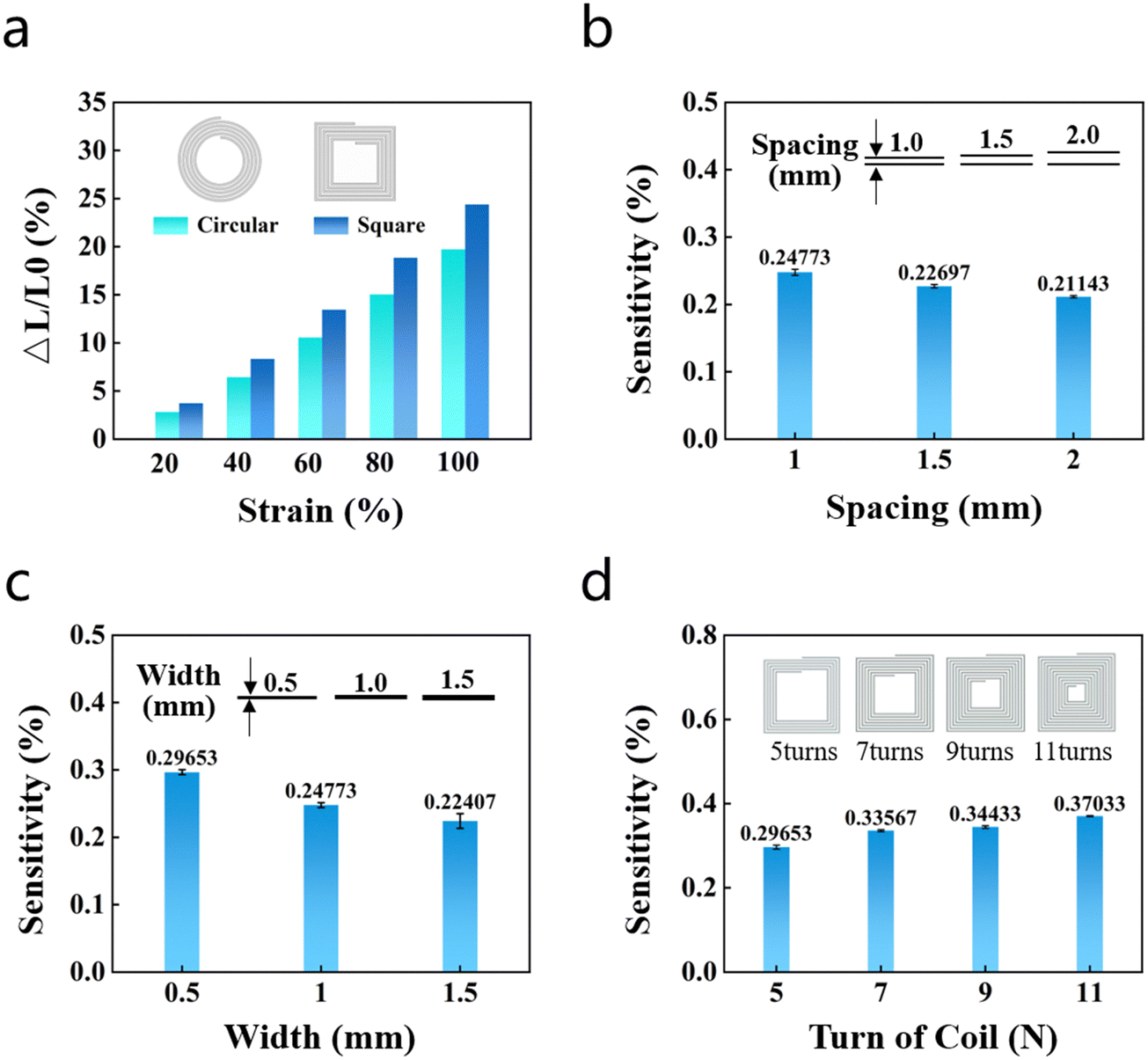 | ||
| Fig. 3 Influence of different structural parameters on the sensitivity of the sensor. (a) Comparison of the changes in inductance between rectangular and circular coils under the same tensile strain. (b) Comparison of the sensitivity of sensors with planar coils and different spacings between the wires (s = 1 mm, 1.5 mm, 2 mm) under a strain of ε = 100%. (c) Comparison of the sensitivity of sensors with planar coils with wires of different widths (w = 0.5 mm, 1 mm, 1.5 mm) under a strain of ε = 100%. (d) Comparison of the sensitivity of sensors with planar coils with different numbers of turns (N = 5, 7, 9, 11) under a strain of ε = 100%. | ||
Next, we also investigated the impact of the spacing between the wires on the sensitivity of the sensor while fixing its size. Three wire spacings were tested—s = 1 mm, 1.5 mm, and 2 mm—while keeping the number of turns (N) fixed at five and the width of the wire (w) at 1 mm. The sensors were subjected to strains ranging from 0% to 100%, and their resulting sensitivities were compared. Three wire widths were tested—w = 0.5 mm, 1 mm, and 1.5 mm—while keeping the number of turns (N) fixed at five and the wire spacing (s) at 1 mm. The sensors were subjected to strains ranging from 0% to 100%, and their resulting sensitivities were compared. The observations showed that the sensitivity of the sensor decreased as the distance between the wires and their width increased (Fig. 3(b) and (c)). Using narrow wires with short spaces between them leads to an increase in the distance between the parallel straight conductors in the coil, thus elongating each conductor. This in turn increases the mutual inductance and sensitivity of the sensor.
To examine the influence of the number of turns (N) of the coil on the sensitivity of the sensor, we tested sensors with four values of turns of the coil (N = 5, 7, 9, and 11), with the width of the wire (w) fixed at 0.5 mm and the spacing between the wires fixed at 1 mm. The results consistently demonstrated an improvement in the sensitivity of the sensor as the number of turns of the coil increased (refer to Fig. 3(d)). This was obtained owing to the larger number of turns, which introduced additional segments of the parallel straight conductor that generated mutual inductance. This led to substantial changes in the mutual inductance ΔM across different sections of the sensor. The experimental findings regarding the effects of the spacing between the wires (s), their width (w), and the number of turns (N) of the coil are summarized in Table 1. It shows that the sensor exhibited the highest sensitivity when N = 11, W = 0.5 mm, and S = 1 mm. We used these parameters as the standard for designing sensors.
| No of coils | Width (mm) | Spacing (mm) | GF |
|---|---|---|---|
| 5 | 1.0 | 1 | 0.248 |
| 1.0 | 1.5 | 0.227 | |
| 1.0 | 2 | 0.211 | |
| 5 | 0.5 | 1 | 0.296 |
| 1.0 | 1 | 0.248 | |
| 1.5 | 1 | 0.224 | |
| 5 | 0.5 | 1 | 0.296 |
| 7 | 0.5 | 1 | 0.335 |
| 9 | 0.5 | 1 | 0.355 |
| 11 | 0.5 | 1 | 0.371 |
Electrical characterization of the sensor
We conducted tests involving the stretching, bending, and folding of the sensor to evaluate its performance. We initially used finite element analysis software to perform mechanical and electromagnetic simulations of the sensor under various tensile conditions (Fig. 4(a)). This allowed us to analyze the relative changes in inductance at different levels of strain. The sensor was stretched under a strain ranging from 0% to 100% in the simulations, and this resulted in an increase of 44.727% in its inductance. The trend of the changes in inductance was consistent with the theoretical analysis provided above (Fig. S4a, ESI†). We subsequently performed a series of stretch-and-release tests on the sensors. The ultimate tensile test was first conducted (Fig. 4(b)), and the sensor was gradually stretched to a strain of 300%. The curve of its measurements exhibited a nearly linear trend, with a 126.864% increase in its inductance at a strain of 300% compared with the initial value. The average change in its inductance at a strain of 100% was 37.94%, which is similar with the results of the simulations. The sensor had an ultra-high resolution, and could detect strains as low as 0.05% at a resolution of 0.05% (Fig. 4(c)). This flexible strain sensor had a minimum limit of detection and a maximum normal operating strain that exceeded those of most recently developed sensors (Fig. S5, ESI†). It also maintained stable values of inductance and exhibited good numerical consistency at marked strains of 20%, 40%, 60%, and 80%. The maximum error in the relative change in inductance at the same strain was only 1.2% (Fig. 4(d)). Furthermore, the sensor exhibited exceptional cyclic stability, as shown in Fig. 4(e), and could endure over 5000 stretch-and-release cycles at ε → 100%. These findings collectively verify the outstanding performance of our sensor under both high and low strains. | ||
| Fig. 4 Tests of the performance of the sensor. (a) Schematic of the sensor in the undeformed state, and the distributions of its stress and potential at a strain of 50%. (b) Changes in the relative inductance of the sensor as it was stretched from a strain of 0% to that of 300%. (c) Changes in the relative inductance of the sensor under cyclic tensile loading with different amplitudes of applied strain ε (small strain). (d) Changes in the relative inductance of the sensor at the same measurement position during stretching and unloading processes. (e) Changes in the relative inductance of the sensor under cyclic stretching (more than 5000 cycles, ε = 100%). (f) Distributions of the magnetic flux density of the sensor under different deformations of bending and folding. (g) Changes in the relative inductance of the sensor with different radii of curvature. (h) Changes in the relative inductance of the sensor at different folding angles. | ||
The changes in the relative inductance of the sensor were tested under bending and folding conditions (Fig. 4(f)). Electromagnetic simulations of the sensor were also performed by using finite element analysis software. The results showed that the inductance of the sensor decreased as its degrees of bending and folding increased. The degree of bending was expressed in terms of the height of the upward bulge at the center of the sensor. Specifically, there is a direct relationship between this height parameter and the degree of bending: smaller height values correspond to less bending, while increasing height values indicate more bending. The results of the simulations in Fig. S4 (ESI†) demonstrate that a reduction in the inductance of the sensor was caused by the cancellation of the magnetic fields generated by the two halves of its coil. Similar results were obtained from the experiments. When sensors with varying radii of curvature were bent, their inductances increased proportionally to the radius of curvature (Fig. 4(g)). During the folding test, the sensor was secured to a rectangular frame-holder and gradually unfolded from 0° to 180°, and this led to a gradual increase in its inductance (Fig. 4(h)). These experimental results were in agreement with those of the simulations, suggesting that the sensor was reliable under folding and bending conditions, and thus has the potential to detect the opening and closing of certain joints of the human body.
Design of detection system
Fig. 5(a) shows the detection circuit created for the sensor. It included an external sensor, a microcontroller, an LDC1614 converter chip, Bluetooth technology, a voltage regulator, and a battery. An oscillating circuit was formed by the inductive sensor and the capacitor to generate an oscillatory frequency (sensor's signal acquisition circuit as shown in Fig. S6, ESI†). The frequency was then measured and converted into a digital signal by the fully integrated inductive-to-digital converter chip LDC1614. The digital signal was then processed by the microcontroller by using the I2C protocol, and was transmitted to the mobile device via wireless communication technology. The circuit board had a size of 3 cm × 3 cm (Fig. 5(b)). A system to monitor human activity was developed by using a flexible, planar, inductive sensor. It consisted of the sensor, a signal processing circuit, and a portable mobile display device as depicted in Fig. 5(c). The principle of detection involved placing sensors on different parts of the human body to detect changes in its movement. The signals collected by the sensors were processed by the signal processing circuit and transmitted via Bluetooth to the mobile device for real-time display. This allowed for the real-time monitoring of various movements of the body. Errors may be introduced to the measured data during the test due to the instability of the circuit, jitter in the sensor wiring, and movements of the human body, and results in interference by noise. To address this issue, we used a sliding-average filtering algorithm to process the raw data (Supplementary Text 2, ESI†). This allowed us to acquire stable and noise-free data while ensuring the real-time performance of the sensor, thus making it suitable for practical systems. | ||
| Fig. 5 Design and functional verification of the system to monitor human activity. (a) Simplified schematic of the circuit. (b) Circuit board. (c) Block diagram of the overall system. (d) Experimental setup for monitoring the breathing of a mannequin. (e) Performance of the system in terms of detecting different breathing patterns of the mannequin. | ||
Fig. 5(d) shows the validation tests performed on a mannequin by using the proposed detection system. The sensor was placed on the mannequin's chest to monitor its expansion and contraction during breathing. Various volumes of air were delivered to the mannequin by using a respiratory bag to simulate different states of breathing. Fig. 5(e) shows that the detection system was able to accurately distinguish between different breathing states of the mannequin. Video S1 (ESI†) shows a demonstration of this ability.
Application of the detection system to monitor human activity
We extended the above system to detect variations in the movement of different parts of the human body and transmit the data simultaneously (Fig. S6 and S7, ESI†). Fig. 6(a) shows the capability of the sensor system to detect the frequency of human respiration, showcasing its ability to differentiate between different states of breathing, including normal and deep breathing. Furthermore, Fig. 6(b) demonstrates the system's capability to detect swallowing in the throat and identify subtle movements during this process. | ||
| Fig. 6 Application of the system to monitor human motion. (a)–(d) Evaluation of the capabilities of the system to monitor respiration, swallowing, and movements of the knee and elbow joints when the human body was static. (e) Schematic representation of the sensor attached to the human body during its motion. (f). Assessment of the capabilities of detection of respiration by the sensor when affixed to the human chest during running, walking, and at rest. (g). Evaluation of the capabilities of detection of the sensor when attached to the knee joint to monitor changes in the bending of the leg during walking. (The test subject was the first author of this paper: Jian Mao). | ||
Fig. 6(c) and (d) show the system's ability to monitor changes in the movements of the knee and the elbow. We tested its ability to detect different states of motion of the legs by placing sensors on the knees. The results show that the system was able to accurately differentiate between the movements of the legs under normal and quick motion. Furthermore, it detected the opening and closing of the elbow joint when the sensor was placed at the appropriate position. These results show that our system can accurately detect motion signals from multiple parts of the body when it is stationary, and can monitor changes in the physiological signals during movement. We also tested the system's ability to differentiate among the patterns of human respiration during running, walking, and stationary states (Fig. 6(e)), and found it to be accurate (Fig. 6(f)). Video S2 (ESI†) demonstrates its effectiveness in detecting real-time breathing during human movement. The reduction in its sensing value was a result of the increased rate of breathing while running. This higher rate of breathing prevented the sensor from returning to its original state before being deformed again by the rise and fall of the chest cavity. Furthermore, as demonstrated in Video S3 (ESI†), our system could detect changes in the bending of the leg during walking (Fig. 6(g)).
Conclusions
In this study, we proposed a planar inductive sensor based on liquid metal putty that exhibits hyperelasticity, a low limit of detection, a high resolution, and good stability. We aimed to improve its sensitivity under high levels of strain. A planar coil with a rectangular shape, 11 turns, a 1 mm wire pitch, and a 0.5 mm wire width was selected after optimization. We simulated changes in its inductance when the coil was stretched, bent, and folded by using finite element analysis software. For empirical testing, we designed sensors that could function properly under a tensile strain of 300% and detect strains as low as 0.05%. The sensor exhibited exceptional robustness and stability when subjected to dynamic stretching and unloading, and could accurately detect complex deformations caused by bending and folding. A signal acquisition circuit was developed for the sensor, and the signals acquired by it were filtered and transmitted in real time via Bluetooth to a mobile device for display. This system was then used to monitor human activity, and was able to monitor large movements of the elbow and knee joints in real time, as well as the subtle movements involved in swallowing and breathing. In addition, the system was able to monitor the signals of breathing and the movements of the legs in real time. The proposed system delivered outstanding performance, which shows that it offers promise for use in wearable electronics for monitoring health and sporting activity.Experimental section
Materials
Liquid metal gallium and indium (99.99%) were purchased from Beijing Founder Star Sci. & Technol. Co., Ltd, Ecoflex00-30 was purchased from Beijing Tiantong Huayi Co. Ltd.Design and fabrication of sensors
(i) The two components of silicone elastomer A and B were mixed 1![[thin space (1/6-em)]](https://www.rsc.org/images/entities/char_2009.gif) :1 by weight. Gallium and indium were mixed in a ratio of 74.5:25.5 by weight, then heated and stirred at 60 °C for 30 minutes to obtain liquid metal putty (LM-P). (ii) To produce an elastomeric substrate film, pre-configured ecoflex00-30 is poured into a spin coater. The film is then placed on the coater and a mask plate is placed on the surface of the elastic substrate. Liquid metal play dough is applied to the mask plate and a winding pattern is formed on the elastic substrate using the coater. (iii) Attach copper lead wires to each end of the coil to act as electrodes. Secure the electrodes in place by applying ecoflex00-30 to the joints. Place the coil on a rotary coater and apply the ecoflex00-30 solution at 700 rpm. Cure the coil in an oven at 60 °C for 30 minutes.
:1 by weight. Gallium and indium were mixed in a ratio of 74.5:25.5 by weight, then heated and stirred at 60 °C for 30 minutes to obtain liquid metal putty (LM-P). (ii) To produce an elastomeric substrate film, pre-configured ecoflex00-30 is poured into a spin coater. The film is then placed on the coater and a mask plate is placed on the surface of the elastic substrate. Liquid metal play dough is applied to the mask plate and a winding pattern is formed on the elastic substrate using the coater. (iii) Attach copper lead wires to each end of the coil to act as electrodes. Secure the electrodes in place by applying ecoflex00-30 to the joints. Place the coil on a rotary coater and apply the ecoflex00-30 solution at 700 rpm. Cure the coil in an oven at 60 °C for 30 minutes.
Finite element simulation of the sensors
COMSOL Multiphysics (version 6.0) was used to simulate the mechanical and electromagnetic properties. The parameters of the elastomer, including Young's modulus (E = 0.2 MPa), Poisson's ratio (ν = 0.4) and relative permittivity (εr = 2.8) were considered, as well as the material parameters of LM-P, including electrical conductivity (σ = 1.55 × 10⁶ S/m), relative permittivity (εr = 1) and relative magnetic permeability (μr = 1). A tetrahedral mesh with adaptive mesh convergence was used to simulate the electromagnetic properties. A 500 mm square was used as the radiation boundary to ensure calculation accuracy.Device characterization
Inductance was measured using a Hioki IM3570 impedance analyser. The transducers were dynamically stretched using a universal materials testing machine (Instron 5943, USA).PCB module design and fabrication
The microcontroller is STM32F103C8T6 (STMicroelectronics, Italy), and the inductive digitizer is LDC1614 (Texas Instruments, USA), which has a four-channel 28-bit inductive digitizer and supports sensor frequencies from 1 KHz to 10 MHz, enabling high performance and reliable inductive detection at very low cost and power consumption. The Bluetooth module is HC-08 (Guangzhou Huicheng Information Technology Co., Ltd, China), the power management module is PW2057 (Shenzhen Yibori Electronics Co., Ltd, China) and the printed circuit boards are manufactured by Shenzhen Jialichuang Technology Group Co.Data availability statement
Data will be made available on request.Conflicts of interest
The authors declare that they have no known competing financial interests or personal relationships that could have appeared to influence the work reported in this paper.Acknowledgements
This research was partially supported by National Key R&D Program China (2023YFC3603500), National Natural Science Foundation of China (52127803, 51931011, 62174165, U22A2075, 52301256, U20A6001, M-0152, U22A20248, 52201236, 62204246, 52105286), Chinese Academy of Sciences YouthInnovation Promotion Association (2018334), Pioneer and Leading Goose R&D Program of Zhejiang (2022C01032), “High-level Talent Special Support Plan” Technology Innovation Leading Talent Project of Zhejiang Province (2022R52004), Natural Science Foundation of Zhejiang Province (LD22E010002), Ningbo Natural Science Foundations (20221JCGY010312, 2022J288 ), Ningbo Key Research and Development Program (2023Z097).Notes and references
- Y. Liu, M. Pharr and G. A. Salvatore, ACS Nano, 2017, 11, 9614–9635 CrossRef CAS PubMed.
- Y. Ma, Y. Zhang, S. Cai, Z. Han, X. Liu, F. Wang, Y. Cao, Z. Wang, H. Li and Y. Chen, Adv. Mater., 2020, 32, 1902062 CrossRef CAS PubMed.
- Z. Shen, F. Liu, S. Huang, H. Wang, C. Yang, T. Hang, J. Tao, W. Xia and X. Xie, Biosens. Bioelectron., 2022, 211, 114298 CrossRef CAS PubMed.
- J. C. Yang, J. Mun, S. Y. Kwon, S. Park, Z. Bao and S. Park, Adv. Mater., 2019, 31, 1904765 CrossRef CAS PubMed.
- T. Q. Trung and N. E. Lee, Adv. Mater., 2016, 28, 4338–4372 CrossRef CAS PubMed.
- D. Hu, Q. Wang, J. Yu, W. Hao, H. Lu, G. Zhang, X. Wang and L. Qiu, J. Nanosci. Nanotechnol., 2016, 16, 5839–5842 CrossRef CAS PubMed.
- C. Deng, L. Lan, P. He, C. Ding, B. Chen, W. Zheng, X. Zhao, W. Chen, X. Zhong and M. Li, J. Mater. Chem. C, 2020, 8, 5541–5546 RSC.
- K. Choi, S. J. Park, M. Won and C. H. Park, Sensors, 2021, 21, 2304 CrossRef PubMed.
- Y. Chen, Y. Zhang, F. Song, H. Zhang, Q. Zhang, J. Xu, H. Wang and F. Ke, Adv. Mater. Technol., 2021, 6, 2100421 CrossRef CAS.
- M. Hu, Y. Gao, Y. Jiang, H. Zeng, S. Zeng, M. Zhu, G. Xu and L. Sun, Adv. Compos. Hybrid Mater., 2021, 4, 514–520 CrossRef CAS.
- S.-R. Kim, J.-H. Kim and J.-W. Park, ACS Appl. Mater. Interfaces, 2017, 9, 26407–26416 CrossRef CAS PubMed.
- L. Cai, L. Song, P. Luan, Q. Zhang, N. Zhang, Q. Gao, D. Zhao, X. Zhang, M. Tu and F. Yang, Sci. Rep., 2013, 3, 3048 CrossRef PubMed.
- X. Guo, Y. Huang, Y. Zhao, L. Mao, L. Gao, W. Pan, Y. Zhang and P. Liu, Smart Mater. Struct., 2017, 26, 095017 CrossRef.
- J. Kim, M. Lee, H. J. Shim, R. Ghaffari, H. R. Cho, D. Son, Y. H. Jung, M. Soh, C. Choi and S. Jung, Nat. Commun., 2014, 5, 5747 CrossRef CAS PubMed.
- Y. Wang, J. Hao, Z. Huang, G. Zheng, K. Dai, C. Liu and C. Shen, Carbon, 2018, 126, 360–371 CrossRef CAS.
- H. Liu, J. Gao, W. Huang, K. Dai, G. Zheng, C. Liu, C. Shen, X. Yan, J. Guo and Z. Guo, Nanoscale, 2016, 8, 12977–12989 RSC.
- X. You, J. Yang, M. Wang, J. Hu, Y. Ding, X. Zhang and S. Dong, 2D Mater., 2019, 7, 015025 CrossRef.
- J. Qin, L. J. Yin, Y. N. Hao, S. L. Zhong, D. L. Zhang, K. Bi, Y. X. Zhang, Y. Zhao and Z. M. Dang, Adv. Mater., 2021, 33, 2008267 CrossRef CAS PubMed.
- T. Kawasetsu, R. Niiyama and Y. Kuniyoshi, 2019 IEEE SENSORS, 2019, pp. 1–4 Search PubMed.
- N. Jeranče, D. Vasiljević, N. Samardžić and G. Stojanović, Sensors, 2012, 12, 1288–1298 CrossRef PubMed.
- A. Prituja, H. Banerjee and H. Ren, IEEE Sens. J., 2018, 18, 3580–3589 CAS.
- Z. Xing, J. Lin, D. McCoul, D. Zhang and J. Zhao, IEEE Sens. J., 2020, 20, 14670–14675 CAS.
- H. Wang, M. Totaro, S. Veerapandian, M. Ilyas, M. Kong, U. Jeong and L. Beccai, Adv. Mater. Technol., 2020, 5, 2000659 CrossRef.
- J. Zhu, Y. Jia, M. Li, Z. Zhou, Y. Chen, Q. Liu and X. Yang, npj Flexible Electron., 2022, 6, 67 CrossRef.
- M. Tavassolian, T. J. Cuthbert, C. Napier, J. Peng and C. Menon, Adv. Intell. Syst., 2020, 2, 1900165 CrossRef.
- R. Wijesiriwardana, IEEE Sens. J., 2006, 6, 571–579 Search PubMed.
- S.-Y. Tang, C. Tabor, K. Kalantar-Zadeh and M. D. Dickey, Annu. Rev. Mater. Res., 2021, 51, 381–408 CrossRef CAS.
- Q. Wang, Y. Yu and J. Liu, Adv. Eng. Mater., 2018, 20, 1700781 CrossRef.
- X. Wang, L. Fan, J. Zhang, X. Sun, H. Chang, B. Yuan, R. Guo, M. Duan and J. Liu, Adv. Funct. Mater., 2019, 29, 1907063 CrossRef CAS.
- C. Okutani, T. Yokota, H. Miyazako and T. Someya, Adv. Mater. Technol., 2022, 7, 2101657 CrossRef CAS.
- L.-Y. Zhou, Q. Gao, J.-F. Zhan, C.-Q. Xie, J.-Z. Fu and Y. He, ACS Appl. Mater. Interfaces, 2018, 10, 23208–23217 CrossRef CAS PubMed.
- A. Fassler and C. Majidi, Smart Mater. Struct., 2013, 22, 055023 CrossRef CAS.
- N. Lazarus, C. Meyer, S. Bedair, H. Nochetto and I. Kierzewski, Smart Mater. Struct., 2014, 23, 085036 CrossRef CAS.
- H.-Y. Chen and A. T. Conn, IEEE Sens. J., 2020, 20, 7384–7391 CAS.
Footnote |
| † Electronic supplementary information (ESI) available. See DOI: https://doi.org/10.1039/d4ma00140k |
| This journal is © The Royal Society of Chemistry 2024 |