
 Open Access Article
 This Open Access Article is licensed under a Creative Commons Attribution-Non Commercial 3.0 Unported Licence
High-throughput screening of stable sulfide semiconductors for solar cell conversion†
Jinjin
Yang
a,
Zhongxiong
Sun
a,
Dao-Xin
Yao
 b and
Man-Rong
Li
*ac
b and
Man-Rong
Li
*ac
aKey Laboratory of Bioinorganic and Synthetic Chemistry of Ministry of Education, School of Chemistry, Sun Yat-Sen University, Guangzhou 510006, P. R. China. E-mail: limanrong@mail.sysu.edu.cn
bGuangdong Key Laboratory of Magnetoelectric Physics and Devices, School of Physics, Sun Yat-Sen University, Guangzhou 510275, P. R. China
cSchool of Chemistry and Chemical Engineering, Hainan University, Haikou 570228, P. R. China
First published on 7th March 2024
Abstract
The application of chemically stable oxide perovskite solar cells confronts substantial obstacles, such as a large band gap and high internal voltage loss, despite the rapid technical development of device fabrication. In contrast, the design and screening of innovative sulfide materials, which is less explored compared with the oxide counterparts, has become a burgeoning research area. Here, screening for new solar cell absorber materials amongst RE3BB′S7 (RE = La, Y; B/B′ = Ti–Cu in the 3d row) is performed via high-throughput calculations. The filtration criteria are thermodynamic/kinetic stability, suitable band gap, carrier effective mass, defect tolerance and optical absorption behavior, which are key parameters to determine whether the material is suitable for semiconducting solar cell absorbers or not. Based on the screening criteria, we identified two appealing candidates, RE3CoCrS7 (RE = La, Y), with potential application in photoelectrochemical devices. These findings established a solid theoretical foundation for the development and implementation of sulfide solar cells in practical applications.
1. Introduction
Efficient harvesting of solar energy is urgently required to solve the impending energy and environmental crisis. A prerequisite is the screening of materials that have high-performance solar energy conversion.1–3 Perovskite materials have demonstrated advantages as light absorbers in solar cells, owing to their outstanding stability in highly oxidizing circumstances, widely tunable band gaps (Eg), high optical absorption rates, long carrier diffusion length, and high carrier mobility. However, two insurmountable problems exist in perovskite oxides: (1) the large Eg for sunlight absorbers due to the low energy of the O 2p orbital contributing to the valence band maximum (VBM), and (2) the anodic VBM with respect to the water redox level resulting in large internal voltage loss in devices.4 Fortunately, both aforementioned issues can be resolved by substituting oxygen with sulfur. Because sulphides can possess relatively high conduction band positions suitable for H2O reduction and better sunlight responses than oxides, which are originated from the higher valence band positions composed of S 3p orbitals. In addition, sulfide perovskites are a more environmentally friendly option than lead halide analogs, and reduce instability and toxicity commonly associated with halide perovskites. Semiconducting perovskite sulfides have been theoretically predicted and experimentally synthesized, showcasing superior electrical and optical qualities that make them ideal for low-cost tandem solar cells. A number of sulfides, such as AZrS3 (A = Ca, Sr, Ba), SrTiS3, CuTaS3, CaSnS3 and SrSnS3, have attracted intense interest in the context of photovoltaic (PV) solar cells.5 Recently, Ruddlesden–Popper (R–P) sulfides A3BB′S7 (also known as A3B2S7 if B and B′ are the same elements) have theoretically and experimentally received great attention as solar conversion materials.6 A3Zr2S7 (A = Ca, Ba) and Ca3Sn2S7, which demonstrate stable ferroelectricity at room temperature with small Eg values (<2.2 eV), are well suited for significant visible-light absorption. The R–P type Ca3Zr2S7 material with low Eg suitable for visible light absorption is anticipated to exhibit stable ferroelectric polarization as a promising ferroelectric photovoltaic material along with high energy conversion efficiency (PCE), where photo-generated electron–hole pairs are effectively separated.7 Moreover, the charge recombination rate in Ca3Sn2S7 can be experimentally tuned to simulate its superior infrared detection performance, showing small carrier effective mass (0.04 m0), ultrahigh room-temperature carrier mobility (6.7 × 104 cm2 V−1 s−1), Fermi velocity (3 × 10⁵ m s−1), and optical absorption coefficient (105 cm−1).8,9 Also, the strained ferroelectric Ba3Zr2S7 thin film possesses a suitable Eg value of 1.6 eV for PV application, absorbing sunlight in a wide range of visible-light spectra. Thus, A3BB′S7 sulfides represent a novel and cost-effective material class for solar cells, offering greater stability than oxide counterparts.10In rare earth (RE) ions, the abundant 4f/5d orbit electrons could generate different intermediate energy states to induce unique photo-physical behavior, suggesting excellent potential in PV based devices. Accordingly, the electronic properties of solar cell materials can be modulated by appropriate RE ions.11 In particular, the incorporation of RE ions has a major effect on the charge carrier mobility, band structure, and absorption/luminescence properties, resulting in modified charge transport dynamics as exemplified in perovskite-related solar cells.12 More significantly, the up-conversion takes place in materials containing trivalent RE ions by the process of ground- and excited-state absorption of multi-photons from actual energy levels.13 In general, when utilizing trivalent RE doped materials as up-converting layers, a single junction connected to an ideal up-conversion layer can achieve a maximum PCE of approximately 47.6% for non-concentrated sunlight and 63.2% for concentrated sunlight. For example, Er/Yb doped M2O2S (M = Gd, Y, La) are used as a reference to show the enhancement of up-conversion emission efficiency under 1550 nm excitation,14,15 and Tb3+–Yb3+ co-doped silicate glass can improve the PCE of monocrystalline silicon solar cells by 8.6%.14 Along these lines, RE3+3BB′S7 are expected to be excellent light absorbers and enhance the PCE of solar cells, considering their chemical and structural similarities with the reported solar energy conversion materials. Ruled by the charge balance, the valence state of B–B′ in RE3BB′S7 can be either monovalent–tetravalent (I–IV) or bivalent–trivalent (II–III) combinations. So far, the most prevalent cases adopted the monovalent–tetravalent (I–IV, B = Cu, Ag; B′ = Si, Ge, Sn) combinations in RE3+3B1+B′4+S7, and mostly crystallized in the La3SiCuS7-type P63 hexagonal structure, such as Y3CuGeS7 and Sm3CuGeS7 identified as outstanding infrared nonlinear optical materials. In contrast, the bivalent–trivalent (II–III) combination RE3+3B2+B′3+S7 has barely been studied as a research object of this work, leaving a vast chemical space to explore new candidates. Structural, magnetism and electrical transport data for La3BIIFeIIIS7 (B = Mn, Fe, Co, Ni) have been experimentally reported, providing experimental validation of upcoming calculations.16 La3BIIFeIIIS7 crystallizes in the non-centrosymmetric hexagonal space group P63 with Z = 2, where crystal structures consist of parallel chains of face-sharing B-centred octahedra and stacking of Fe-centred tetrahedra with seven-coordinated La atoms in the intervening spaces. Based on previous magnetic and electric tests, La3BIIFeIIIS7 (B = Mn, Fe, Co, Ni) sulfides are p-type semiconductors and have higher magnetic moments at high-temperatures than those at low temperatures, except for the nickel compound, because of the probable interaction between octahedral site B and tetrahedral site Fe.16
The performance of solar cell light absorbing materials depends not only on the process of device fabrication, but also on the electrical and optical properties of the original materials. However, it is difficult and costly to measure the microscopic -properties of materials experimentally. There is a need for theoretical prescreening to reveal the intrinsic mechanisms and inherent properties of new potential candidates for light absorption layers in solar cells. Recently, data-driven and high-throughput computing (HTC) assisted approaches have facilitated significant time and cost savings. The key points are to explore the correlations of band structure, light absorption, carrier mobility and defect tolerance to guide and accelerate the discoveries of new light absorption layer materials. In this work, we present a comprehensive screening of 128 possible candidates in RE3+3B3+B′2+S7 (RE = La, Y; B and B′ are Ti–Cu in the 3d row of the periodic table of elements) to attentively seek suitable solar cell absorption materials. We perform density functional theory (DFT) based HTC, considering formability of 672 different RE3+3B2+B′3+S7 candidates in seven potential polymorphs along three magnetic configurations. The screening workflow is displayed in Fig. 1, including data-mining and HTC. It should be noted that some compounds in the RE3+3B3+B′2+S7 system have been experimentally reported,17–23 which boosts the examination and validation of suggested approaches through the initial computation test.
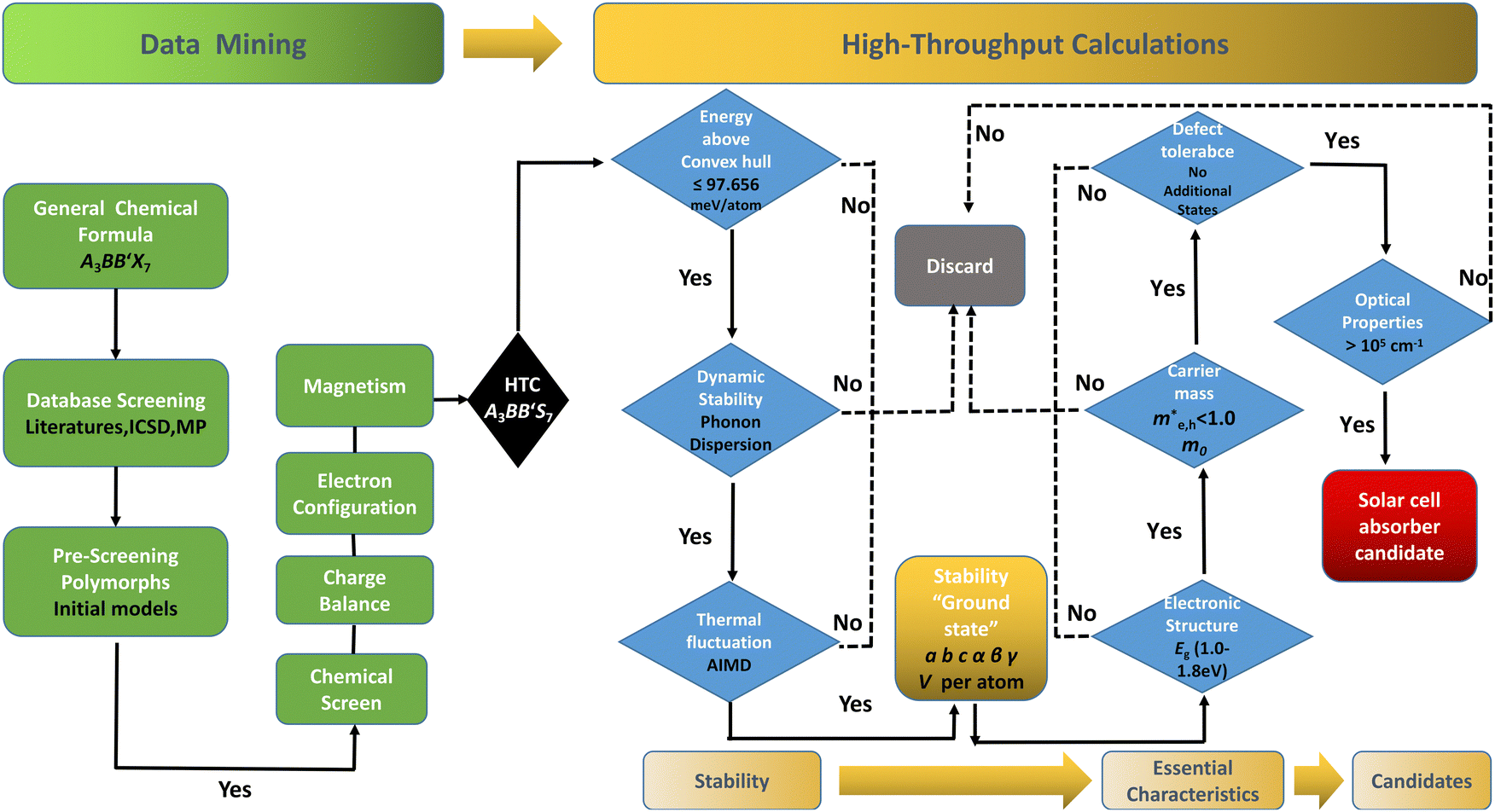 | ||
Fig. 1 Workflow of the data mining and HTC procedure to screen solar cell absorber materials. Data mining: data mining for the A3BB′S7 general formula to find possible polymorphs with confinement(s) by geometric restraints (ionic radius, tolerance factor, distortion, tilting, etc.) and defined characters (magnetism, spin–orbit coupling, charge balance, electron configuration, etc.), and then execute chemical screening to build initial structural models for calculations. HTC: formation energy convex hull screening in Materials Project (Ehull 97.656 meV per atom), and the ones with targeted Eg values of 1.0–1.8 eV with the GGA+U approach remain in the funnel. The mobility of electrons and holes is considered by calculating the effective mass ( ). The defect tolerance is studied to confirm that any potential defect state is not contributing to deep gap recombination sites. ). The defect tolerance is studied to confirm that any potential defect state is not contributing to deep gap recombination sites. | ||
Our screening unveils a short list of potential thermodynamically and kinetically stable candidates with suitable Eg for solar cell absorbers, giving two final winners. RE3CoCrS7 (RE = La, Y) with appropriate Eg values of 1.02 (La based) and 1.00 (Y based) eV are predicted to have small carrier effective masses of electrons and holes at the VBM and a conduction band minimum (CBM) causing high mobility and low recombination rate of photo-generated charge carriers, which are necessary for efficient solar cell conversion. The proposed two candidates are identified to be tolerant to vacancies, since the introduction of defects does not give rise to deep gap recombination sites. A strong light absorption coefficient in the visible region is proposed, as evidenced by their calculated optical absorption.
2. Methods
In the frame of DFT, the Vienna ab initio simulation package (VASP)24,25 adopted projector-augmented wave (PAW)26 in structural relaxation and electronic structure investigation, and generalized gradient approximation (GGA) implemented in the Perdew–Burke–Ernzerhof (PBE) method was employed. The convergence of cut-off energy, k-points and Gaussian broadening was tested to ensure the accuracy of conclusionss. The plane wave cut-off energy was 700 eV. The k-point mesh was 9 × 9 × 9 for monoclinic (C2/m and P21/c) and tetragonal (P42/mnm and I4/mnm) symmetries, 7 × 7 × 9 for hexagonal (P63) symmetry, and 5 × 3 × 5 for orthorhombic Pbam and Cccm symmetry, ensuring that the geometric optimization and static electronic calculations are minimized in the constraint of periodic boundary conditions. The energy and force convergence threshold were set as 1.0 × 10⁻⁶ eV and 1.0 × 10⁻² eV Å−1, respectively. The exchange correlation energy was treated by GGA-PBE. To lessen the inaccuracy brought by strong on-site Coulomb interactions, electron–electron Coulomb repulsion interactions (U) for 3d transition metal elements were considered in the rotationally invariant form (GGA+U), which go beyond the conventional local-density approximation. Standard Hubbard U corrections were adopted for Ti (4.0 eV), V (3.25 eV), Cr (3.7 eV), Mn (3.9 eV), Fe (5.3 eV), Co (3.32 eV), Ni (6.2 eV) and Cu (7.0 eV) as discussed in detail in literature studies and the existing Materials Project (MP) database.27 The given standard set of Hubbard U corrections would be suitably transferrable to magnetic characteristics.27,28 The Heyd–Scuseria–Ernzerhof (HSE06) functional was employed to systematically improve the calculation accuracy for the electronic structure. The phonon dispersion was calculated using the Phonopy package with the finite displacement method along the main symmetry directions in a three-dimensional Brillouin zone.293. Results and discussion
3.1 Data mining and initial computing models
The distribution of preliminarily screened energy above convex hull (Ehull) of formation energy and PBE Eg for 203 known A3B2S7 and A3BB′S7 chemical formulae found in the inorganic crystal structure database (ICSD), Materials Project (MP) database and reported literature as our initial database is plotted in Fig. 2(a). Obviously, compounds with higher Ehull values are more unstable and are anticipated to be metallic. To further motivate the choice of structures and chemical combinations considered in the calculations based on the known A3B2S7 and A3BB′S7 from data mining,22,30–32 seven possible polymorphs as initial structural models for A3BB′S7 are shown in Fig. 2(b). The corresponding lattice parameters, perovskite-related tolerance factors, and basic properties of representative compounds in each polymorph are summarized in Table S1 (ESI†). As shown in Fig. 2(b)-i: (1) the monoclinic C2/m layered structure, as found in Y3Y2S7 (A = B = B′ = Y) where the face-sharing pyramidal BS5 extends along the b-axis forming a linear chain.33 (2) The monoclinic P21/c is exemplified by Ba3Sn2S7 (Fig. 2(b)-ii).34 The corner-sharing BS4 tetrahedra run along the b axis. (3) Orthorhombic Pbam as shown in Eu3Sn2S7 (Fig. 2(b)-iii),35 where the corner-shared BS4 forms a one-dimensional chain along the c axis. (4) The hexagonal P63 as reported in La3SiCuS7 (see Fig. 2(b)-iv) consists of six-coordinated B cations aligned along the c axis, forming a chain structure by face-sharing BS6 octahedra.21 Hexagonal P63 is the most frequently identified structure in contrast to the other six rare ones. (5–7) Three perovskite-type structures related to the R–P phase are shown in Fig. 2(b)-v, vi, vii, where the crystal structures are exemplified by three distinct polymorphs of Ba3Zr2S7,8,36,37 namely orthorhombic Cccm (Fig. 2(b)-v), tetragonal P42/mnm (Fig. 2(b)-vi), and I4/mmm (Fig. 2(b)-vii), respectively. These series consist of perovskite structure blocks separated by extra rock-salt layers along the [001] direction. The orthorhombic Cccm is a distorted variant related to the perovskite structure,38 while the tetragonal I4/mmm with an ideal body-centered structure can be regarded as double layers of BS6 octahedra along the c-axis separated by rock-salt layers. In the slightly distorted tetragonal P42/mnm structure, the perovskite slabs and rock-salt layers stagger along the [001] direction. Within the perovskite layers, the octahedra are corner-shared along [110] and [1−10] and tilted along one of the in-plane directions. Here, the above seven structural prototypes are the most likely polymorphs for A3BB′S7, and thus are adopted as the initial structure models in subsequent HTC.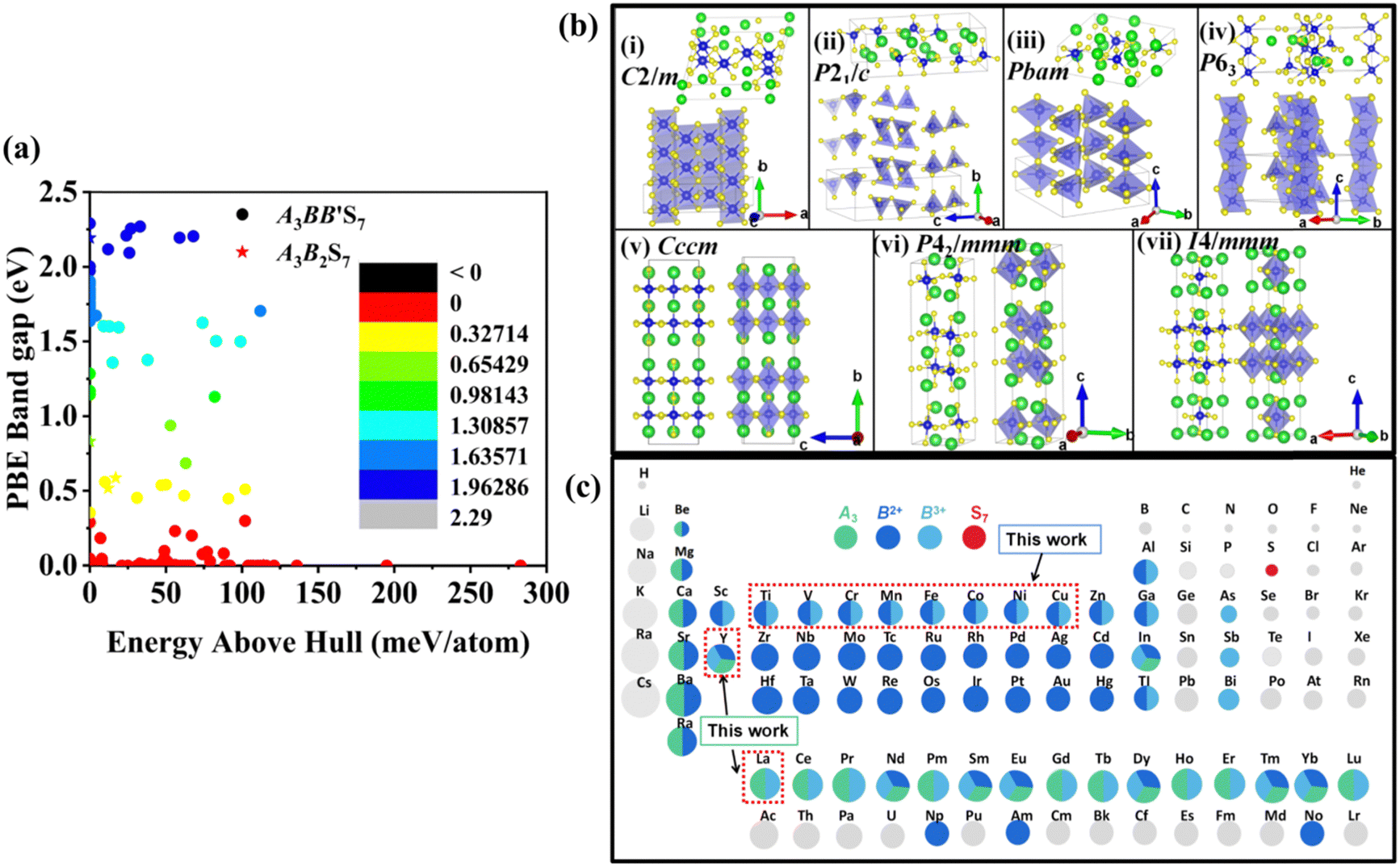 | ||
| Fig. 2 Data mining and initial computing models. (a) Distribution of calculated energies above Ehull and PBE Eg. The scatter plot illustrates the distribution of calculated energies above Ehull and Eg values for 203 A3B2S7 and A3BB′S7 compounds. (b) The most common prototypes for the A3BB′S7 chemical formula by data mining. The unit cell structure and local polyhedral connection are addressed for clarity. (c) Periodic table of the elements considered in A3B2+B′3+S7 with A, B2+, B′3+ and S sites marked in green, dark blue, light blue and red, respectively. If one element is half or one third colored, it means that it can be at two or three sites. | ||
Chemical screening of all possible polymorphs of (A3+)3(B2+)(B′3+)(S2−)7 chalcogenides, where A, B, and B′ can be 23, 48, and 30 conceivable elements under a charge balance, respectively, and the combinations of theoretical 33![[thin space (1/6-em)]](https://www.rsc.org/images/entities/char_2009.gif) 120 (23 × 48 × 30) candidates are shown in Fig. 2(c). According to charge neutrality, the sum of cationic oxidation states should be +14 corresponding to the value of −14 from the sulfur anion. The targeted 128 (RE3+)3(B2+)(B′3+)(S2−)7 compounds (RE = La, Y; B/B′ = Ti–Cu in the 3d row in the periodic table) over the chemical space are restricted by the charge balance and geometrical confinement, as seen in Fig. 1 (data mining). So far, any significant portion of virtual chemical combinations has not been studied yet. Thus, it is urgent to implement further validation for the synthesizable and practical chemical combinations following the workflow in Fig. 1 and Fig. S1 (ESI†).
120 (23 × 48 × 30) candidates are shown in Fig. 2(c). According to charge neutrality, the sum of cationic oxidation states should be +14 corresponding to the value of −14 from the sulfur anion. The targeted 128 (RE3+)3(B2+)(B′3+)(S2−)7 compounds (RE = La, Y; B/B′ = Ti–Cu in the 3d row in the periodic table) over the chemical space are restricted by the charge balance and geometrical confinement, as seen in Fig. 1 (data mining). So far, any significant portion of virtual chemical combinations has not been studied yet. Thus, it is urgent to implement further validation for the synthesizable and practical chemical combinations following the workflow in Fig. 1 and Fig. S1 (ESI†).
The contribution of spin–spin interaction (magnetic structure) in 3d transition metals has proven to be critical to calculate the minimum energy for each initial structural model.39–41 Determining the magnetic configuration is a highly nontrivial task, and one can only locate the magnetic ground state within the space of a limited number of initial configurations. In this work, we restrict the collinear magnetic structures to feature HTC, since there are numerous possible noncollinear magnetic structure models, making it impossible for any comprehensive calculations. In fact, the energy difference between the collinear and noncollinear magnetic structures is found to be insufficient to modify the overall results.42,43 In RE3BB′S7 (RE = La, Y; B/B′ = Ti–Cu in the 3d row), we take the cationic arrangements and selected magnetic 3d B/B′ cations into account to match expected correlations. For the R–P phase Cccm, I4/mmm and P42/mnm, three-type arrangements of the magnetic moments are considered: ferromagnetic (FM) and two antiferromagnetic (AFM) structures, including FM with all moments ferromagnetically aligned, AFM1 with the FM alignment within BS6 layers and AFM coupling between layers, AFM2 with entirely AFM both within and between BS6 layers. For the hexagonal P63 structure, there are three possible magnetic configurations, including the FM (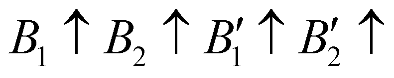 ), AFM1 (
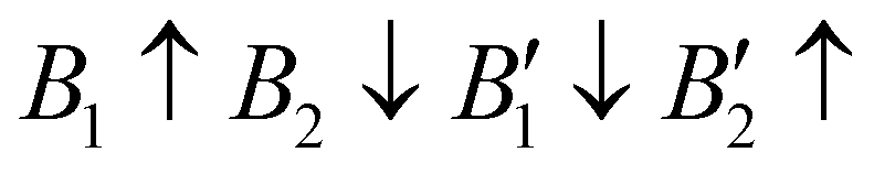 ) and AFM2 (
 ). For other polymorphs, the FM and multiple AFM magnetic configurations are established. The seven screened structures are endowed with spin configurations as shown in Fig. S2 (ESI†). Partial structural optimization energies of La3B2S7 (B = Ti–Cu) are listed in Table S2 (ESI†) to find the lowest energy of the magnetic structure. Since almost all known A3BB′S7 (B ≠ B′) compounds crystallize in the hexagonal P63 structure based on extensive data screening and literature reports,17–19,21,30,44 the potential candidates most likely lie in this symmetry. To save computing resources, for the 56 La3BB′S7 (B ≠ B′) compounds, there are 168 magnetic structures [56 × 1 (hexagonal P63) × 3 (three kinds of magnetic configuration)] to be calculated. In the 8 La3BB′S7 (B = B′ = Ti–Cu in the 3d row) cases, 168 (8 × 7 (seven structural models) × 3 (three kinds of magnetic configuration)) magnetic structures are examined. So, La3BB′S7 totally generates 336 possible magnetic structures. A similar situation occurs in 8 Y3BB′S7 (B = B′ = Ti–Cu in the 3d row) cases. Next, the 672 (336 (La-based) + 336 (Y-based)) possible magnetic configurations are passed for HTC based DFT. During optimization, the lattice parameters and atomic positions of these structures are set to be completely relaxed relative to the original structure. All internal atomic coordinates have been relaxed by total energy minimization in our calculations to find the most stable structure for each chemical composition. If the initial structure undergoes limited symmetry-breaking displacement during structural optimization, then in some cases the crystal structure undergoes dramatic changes.
3.2 HTC
For more predictive and affordable screening results, the chemically screened dynamics and thermodynamically stable compounds are initially calculated in all possible polymorphs over the whole chemical space under the charge balance. Only the stable combinations with targeted suitable Eg remain, and the mobility of an electron (e) and a hole (h) is also taken into account by calculating the carrier effective mass ( ). Finally, the defect tolerance of surviving compounds is studied to distinguish the potential defect state that does not contribute to deep-gap recombination sites.45 The distribution of the absorption spectrum in the visible region indicates the absorption intensity of potential RE3BB′S7 (RE = La, Y; B/B′ = Ti–Cu in the 3d row) solar cell absorber candidates to achieve the best PCE.
3.2.1.1 Formability filtration. It is instructive to analyze the energy distance of the most stable polymorph to the energy convex hulls Ehull constituted by the stable compounds (Ehull = 0 meV per atom) approved in the MP database. Specifically, the thermodynamic stability is evaluated by considering all reactions in which the compound decomposes into stable components. Only the compounds with Ehull lower than thresholds are supposed to be synthesizable.46 In order to ensure the reported La3BFeIIIS7 (B = Mn, Fe, Co, Ni) compounds locate on or even below the convex hulls, 97.656 meV per atom for La3FeMnS7, the maximum value of known series in this category, is set as the threshold for screening potential thermodynamically stable or metastable compounds. It should be pointed out that the MP database does not contain all possible decomposition products for some compounds, meaning that the calculated energy above Ehull serves only as a lower boundary and actual thermodynamic stability could be lower than predicted. Detailed calculation results of the 128 RE3BB′S7 in the magnetic polymorph ground state are listed in Tables S3 and S4 (ESI†), and the cases including on/below Ehull are displayed in Fig. S1 (ESI†) (HTC 1). As shown in Fig. 3(a) and (b), the instability considerably increases with the lengthened energy distance to the convex hull. Employing the boundaries on energy above hull narrows down the search space for synthesizable 94 (128 minus 34) candidates, including 56 La- and 38 Y-based compounds on or below the threshold, indicating that they are thermodynamically stable at 0 K. The Ehull benchmark rules out 34 (including 8 La- and 26 Y-based compounds) of the 128 combinations, since they dock above the convex hull and are thermodynamically not synthesizable. Preliminary screening on the electronic structure shows that only 22 (11 La- and 11 Y-based) out of the 94 combinations in the perfect structure are non-zero Eg, as seen in Fig. S1 (ESI†) (HTC 2).
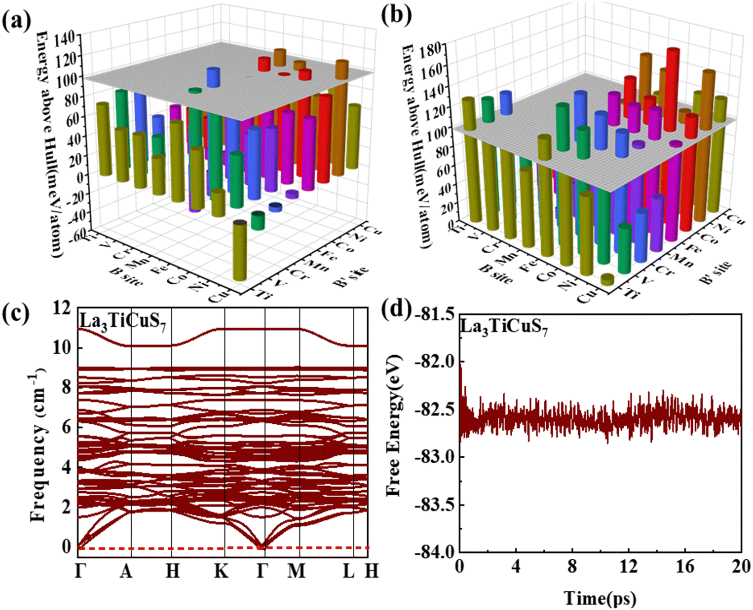 | ||
| Fig. 3 The stability of the considered combinations. Distribution of the distances to the convex hull of (a) La3BB′S7 and (b) Y3BB′S7. (c) Phonon dispersion and variations of representative La3TiCuS7. (d) The total potential energy with respect to the simulation time during AIMD simulations of La3TiCuS7. | ||
3.2.1.2 Kinetic stability and thermodynamic stability. In condensed-matter physics, phonons are used to describe the simple harmonic vibrations of lattices. Thereby, the phonon spectrum is a good characteristic tool to evaluate the kinetic stability evaluated from finite-difference phonon calculations.29 When the phonon spectrum is all above 0 cm−1, it means that the material has no imaginary frequency and is relatively stable. We subsequently investigate the kinetic stability of these 22 combinations with non-zero Eg. The phonon spectra of La3TiCuS7 without the virtual frequency is exemplified in Fig. 3(c). Partial phonon dispersion of selected stable partial sulfides without an imaginary frequency are shown in Fig. S3 (ESI†). Among the 22 calculated combinations, 18 (8 La-based and 10 Y-based) compounds are found to have no imaginary phonon modes, being dynamical lattice stable at T = 0 K. La3MnCoS7, La3V2S7, La3Ni2S7, and Y3V2S7 are discarded because of the strong virtual frequency.
Additionally, for Ehull and phonon dispersion calculations it should be noted that these are zero-temperature calculations, and the stability could be altered by finite temperature contributions to the free energy. In other words, the entropy factors in free energy may cause some of the compounds that are anticipated to be unstable at 0 K to turn out to be stable at ambient temperature. The consideration of finite temperature stability can be undertaken as further efforts. Based on ab initio molecular dynamics (AIMD) examination,47 the energy and temperature in the molecular dynamics simulation process are extracted to prove thermodynamic stability. As the finite energy fluctuates, it is supposed to be relatively stable at 300 K, when the structure is changed without being destroyed. For example, the AIMD simulation results and variations of the total potential energy for La3TiCuS7 is exemplified in Fig. 3(d), which exhibits a small energy fluctuation and hardly distorted crystal structure. The calculated AIMD results of other partially squeezed stable compounds are shown in Fig. S4 (ESI†). Overall, the 18 (8 La- and 10 Y-based compounds) combinations with finite energy fluctuations and robust structure at 300 K are listed in Table 1 and Fig. S1 (ESI†) (HTC 3). These 18 compounds with desirable stability and non-zero Eg are now passed to the next step to examine the electronic structure with further filtration.
 (m0) of selected 18 combinations. The candidates with bold and italicized fonts meet the screening criteria of Eg values in the range of 1.0–1.8 eV and carrier effective masses of less than 1.0 m0
| Combinations | E g |
|
|
Combinations | E g |
|
|
|---|---|---|---|---|---|---|---|
| La3TiCoS7 | 0.83 (direct) | 18.40 | 0.89 | Y3TiCoS7 | 0.69 (indirect) | 18.65 | 0.29 |
| La3TiCuS7 | 1.44 (indirect) | 1.33 | 1.02 | Y3TiCuS7 | 1.59 (indirect) | 0.79 | 0.33 |
| La3VMnS7 | 1.43 (direct) | 1.89 | 1.13 | Y3VMnS7 | 1.38 (indirect) | 2.00 | 0.41 |
| La3CrCuS7 | 0.74 (direct) | 0.31 | 0.24 | Y3CrVS7 | 0.70 (indirect) | 0.56 | 0.70 |
| La3MnCrS7 | 1.07 (direct) | 1.00 | 0.55 | Y3CrMnS7 | 0.83 (indirect) | 1.21 | 0.31 |
| La3FeMnS7 | 1.23 (direct) | 0.70 | 2.50 | Y3CrCuS7 | 0.68 (indirect) | 0.29 | 0.25 |
| La3FeNiS7 | 0.62 (indirect) | 0.30 | 0.54 | Y3MnCrS7 | 0.90 (direct) | 1.07 | 0.39 |
| La3CoCrS7 | 1.02 (direct) | 0.79 | 0.20 | Y3MnCoS7 | 0.49 (direct) | 1.16 | 0.34 |
| Y3FeMnS7 | 1.05 (indirect) | 0.96 | 1.79 | ||||
| Y3CoCrS7 | 1.00 (direct) | 0.54 | 0.42 |


In order to screen the target Eg, we examine the electronic characteristics of the 18 (8 La- and 10 Y-based) stable cases to gauge the band structures and electronic density of states (DOSs). Nine (5 La- and 4 Y-based, as seen in Fig. S1 (ESI†) (HTC 4)) promising compounds with Eg values of 1.0–1.8 eV among the 18 stable compounds are singled out. As listed in Table 1, the 9 candidates in bold are reserved for the next screening process, and the rest are removed due to inappropriate Eg. In most cases, the gaps are indirect, but for some systems the gaps are direct, as seen in Fig. S5 (ESI†). The latter ones are particularly relevant for thin photo-absorbers because of the higher absorbance. Specifically, for these 9 compounds, we further calculate the Eg value using the HSE06 functional. In the GGA+U method, the Eg values of La3CoCrS7 and Y3CoCrS7 are 1.02 and 1.00 eV, close to the 1.75 and 1.69 eV obtained by the HSE06 method, as seen in Fig. 4(a) and (b) and Fig. S6a, b (ESI†). In addition, for Y3TiCuS7, the Eg values are 1.56 and 1.93 eV from GGA+U and HSE06 methods, respectively, as shown in Fig. 5(a) and (b). GGA+U calculations show good agreement with those from HSE06 computations, indicating that GGA+U can offer trustworthy insights into this family. The three compounds mentioned above meet the screening criteria of optimal Eg. Next, the distributions of the electron structure are taken into account. A comprehensive and rational explanation has been provided for the analysis of the valence electron state density in 3d transition metal elements. This elucidation serves as a sound basis for understanding the electronic structure and behavior of these elements within the context of the mentioned compound, for which the DOSs in La3CoCrS7 are plotted in Fig. 4(a) and (b) from GGA+U and HSE06 methods. This shows that electron distributions in the vicinity of the Fermi level are Co 3d/Cr 3d and S 3p states. The Co 3d/Cr 3d states mainly are more localized in lower energy (−4 to −1 eV), which results in the Co 3d/Cr 3d–S 3p reduced hybridization in a higher energy region (−2 to −0.5 eV). This suggests that La3CoCrS7 has innate ionic and unique covalent bonds, owing to the high covalency of sulphur atoms. Taking the experimentally synthesized La3FeMnS7 as a validated example, the band structures and DOSs are obtained with the Eg values of 1.17 and 1.73 eV from GGA+U and HSE06 methods as shown in Fig. S7 (ESI†). It exhibits semiconducting behavior with a direct Eg value of about 1.17 eV, i.e., the CBM and VBM positioned at the K point. The presented semiconductor-like properties are in good agreement with the experimental resistivity-temperature curves of La3FeMnS7 as an n-type semicondctor.16 The AFM configuration is found to be magnetic ground state by comparing the energy of the optimized unit lattice with different magnetic configurations, in line with experimental linear chain antiferromagnetism. In brief, 9 (5 La- and 4 Y-based) compounds, as shown in Fig. S1 (ESI†) (HTC 4), meet the Eg screening criteria and are passed to the next step in the screening process, namely, the exploration of carrier transport.
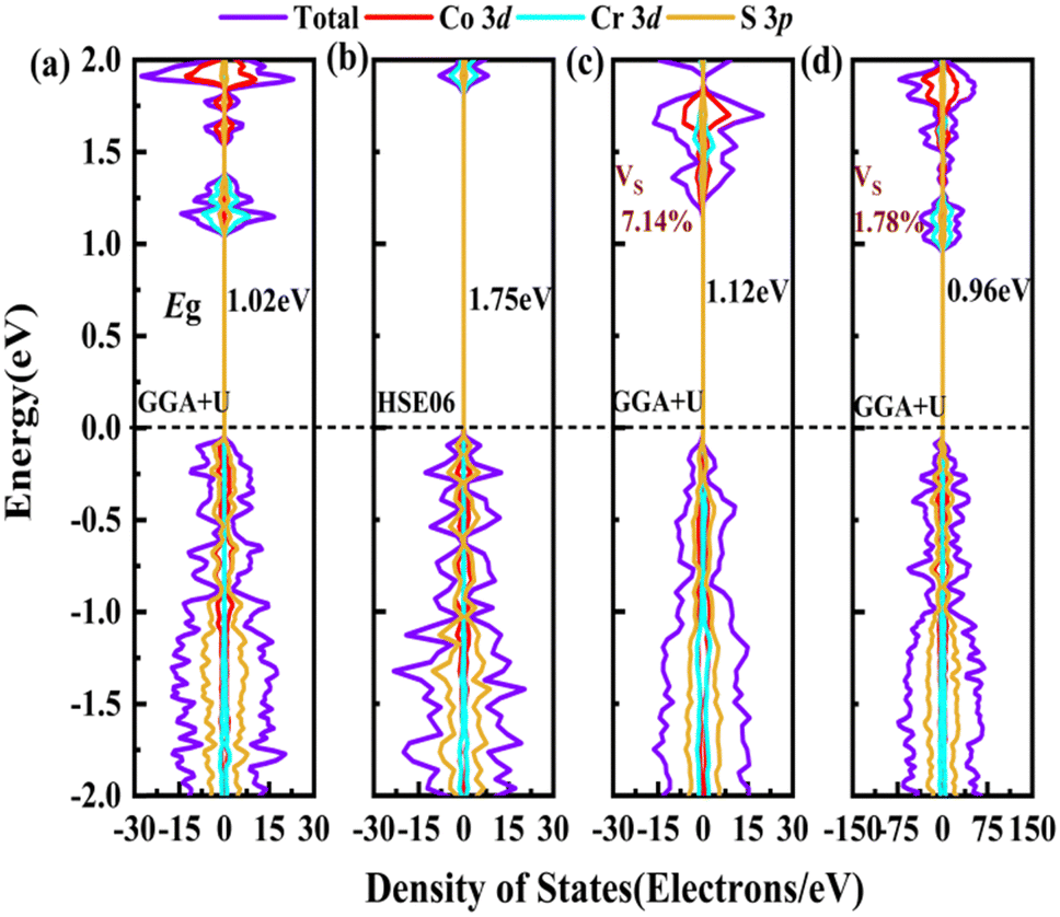 | ||
| Fig. 4 The electronic structures of La3CoCrS7. The total DOSs for pristine La3CoCrS7 from (a) GGA+U and (b) HSE06 methods. The total DOSs for La3CoCrS7 with S vacancy concentrations of (c) 7.14% and (d) 1.78% from the GGA+U method. No additional bands are produced. The zero of the energy is set at the Fermi level. | ||
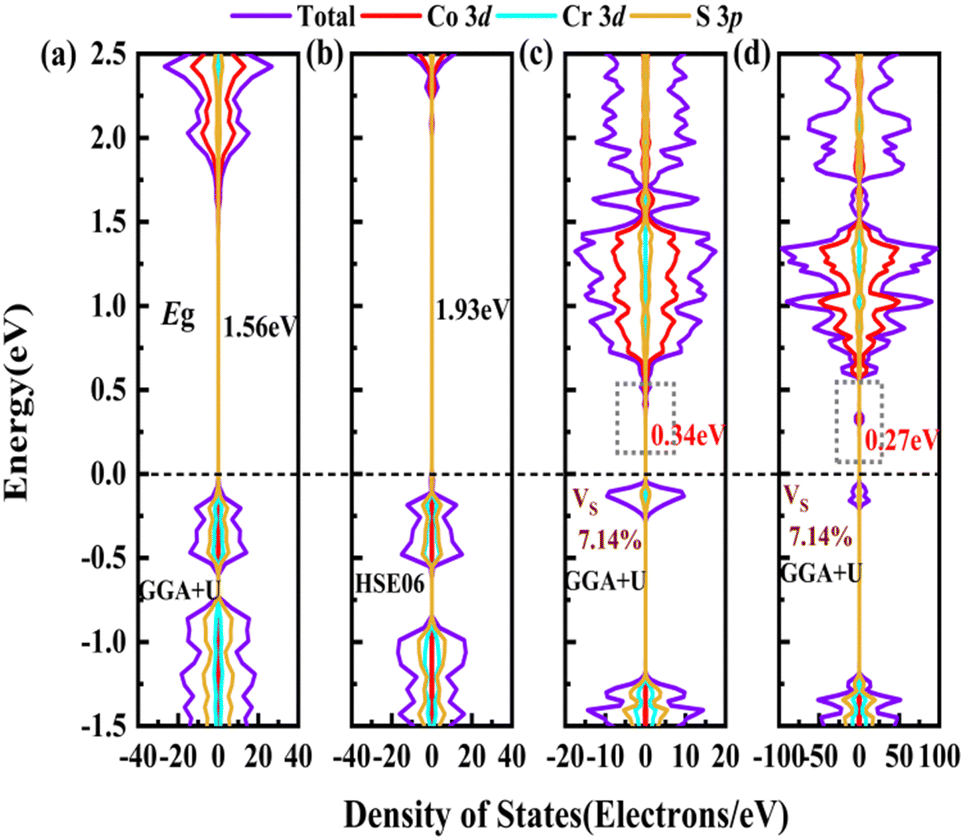 | ||
| Fig. 5 The electronic structures of Y3TiCuS7. The total DOSs for pristine Y3TiCuS7 from (a) GGA+U and (b) HSE06 methods. The total DOSs for Y3TiCuS7 with S vacancy concentrations of (c) 7.14% and (d) 1.78% from the GGA+U method. Additional bands are generated to reduce the Eg value. The zero of the energy is set at the Fermi level. | ||
 and
and  are less than one m0 as listed in Table 1. Carrier effective mass is obtained by fitting parabola to the VBM and CBM according to band structures calculated along high symmetry points. For instance, by fitting the dispersion relationship between the VBM and the CBM in the band structure diagrams of Y3TiCuS7, the carrier effective mass of electrons and holes can be obtained, in which the
  values are 0.79 m0 and 0.33 m0 for
  . Y3TiCuS7 in line with our screening criteria properties is now passed to the next step to consider the influence of defects. The carrier masses of La3TiCuS7 are all larger than 1.0 m0, in which the
  values are 1.33 m0 and 1.02 m0 for
  , so La3TiCuS7 is removed from the filtering path. From the obtained electronic band structures of experimentally synthesized La3FeMnS7, we found that both conduction band edges exhibit tiny amounts of dispersive components, suggesting heavy carrier effective masses. For La3FeIIIMnIIS7, the electron and hole effective masses are 0.7 and 2.5 m0, due to the half-full electronic configuration of the high-spin d5-Mn2+ in octahedral coordination. Since the d–d transition of this configuration is forbidden in quantum mechanics, La3FeMnS7 is ruled out. Finally, 6 (9 minus 3) compounds (La3TiCuS7, La3MnCrS7, La3VMnS7, La3FeMnS7, Y3FeMnS7 and Y3VMnS7) are expelled from our final list because of large carrier effective masses. As seen in Fig. S1 (ESI†) (HTC 5), only La3CoCrS7, Y3CoCrS7 and Y3TiCuS7 satisfy the following condition with
  less than one m0 and are considered as potentially interesting candidates for PV applications to be the focus of further analysis.
For survived La3CoCrS7, Y3CoCrS7 and Y3TiCuS7, we further calculated the effect of point defects on the electronic structure. All possible intrinsic point defects include seven types of vacancies (VLa,Y, VCo,Cr,Ti,Cu, VS). The defect tolerances of selected candidates are explored by performing defect calculations on the supercells for seven vacancies in La3CoCrS7, Y3CoCrS7 and Y3TiCuS7. The analysis exclusively focuses on neutral defects. It should be stressed that the defect states cannot be expected to be treated accurately at the level of a semi-local exchange–correlation functional as applied here due to the underestimation of the Eg and the delocalization error. The primary goal here is not an in-depth investigation into the precise positions or characteristics of defect levels. Instead, the objective is a qualitative assessment to ascertain whether defect states exist within the Eg. Deep gap states are always caused by an anionic vacancy while the cation vacancy does not seem to introduce deep gap states. Next, we study the presence of a deep lying state in the gap for the S vacancy, showing up as a contribution to the DOSs in the region of the Fermi level. The defect sensitivity for the S vacancy in the three cases is discussed below. Particularly, the vacancy concentration is critical to electron structure properties. In the calculations, S defect concentrations are constructed, namely, 7.14% (La6Co2Cr2S13 (Fig. 4(c)), Y6Co2Cr2S13 (Fig. S6c, ESI†) and Y6Ti2Cu2S13 (Fig. 5(c))), 1.78% (La24Co8Cr8S55 (Fig. 4(d)), Y24Co8Cr8S55 (Fig. S6d, ESI†) and Y24Ti8Cu8S55 (Fig. 5(d))), respectively. It turns out that the introduction of the S vacancy in the cases of La3CoCrS7 and Y3CoCrS7 does not give rise to additional states inside the Eg. Defect states close to the band edges and a slight change in Eg are recognized with 1.12 and 1.05 eV for 7.14% (0.96 and 0.85 eV for 1.78%) defect concentrations, respectively. So, La3CoCrS7 and Y3CoCrS7 demonstrate defect tolerance. However, deep states in Y3TiCuS7 are found within the Eg, regardless of the defect concentration being 7.14% or 1.78%, so it exhibits defect sensitivity with obvious decreased Eg, about 0.34 and 0.27 eV at S vacancy concentrations of 7.14% and 1.78%. Hence, Y3TiCuS7 is discarded from our proposed list of materials due to additional states from the sulfur vacancy. Finally, 2 out of the 3 candidates, RE3CoCrS7 (RE = La, Y) are equipped with vacancy tolerance as shown in Fig. S1 (ESI†) (HTC 6), and screened out as potential materials for solar energy conversion applications.
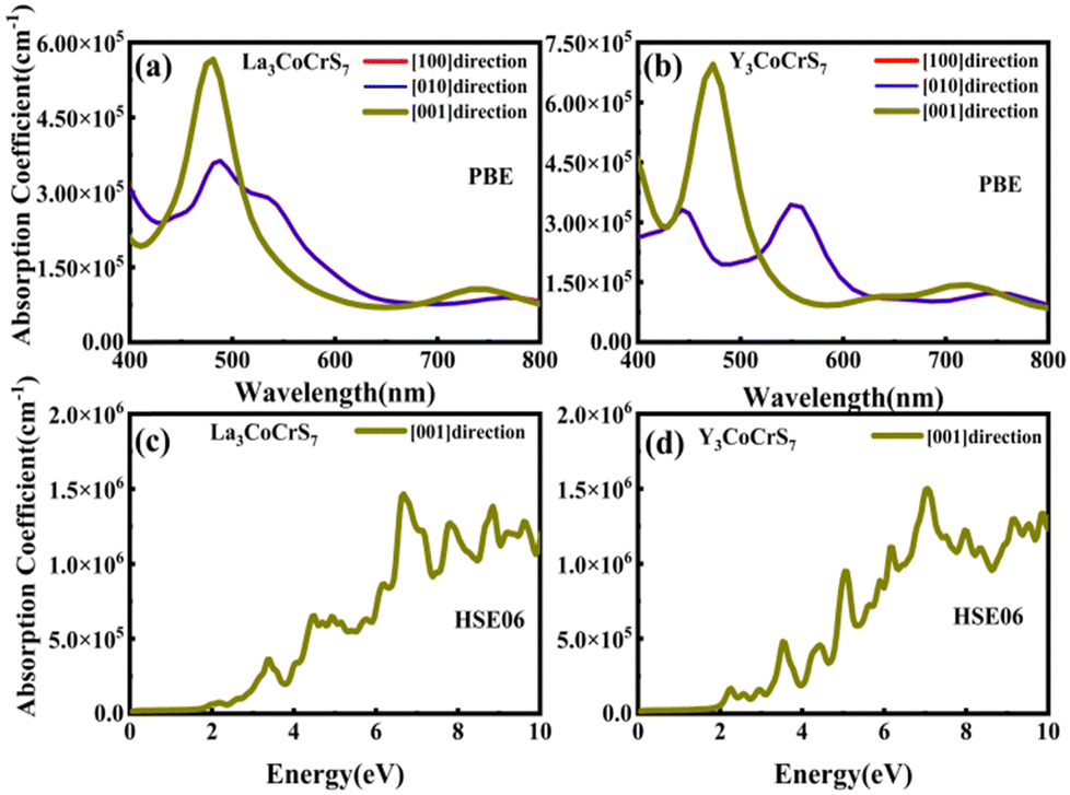 | ||
| Fig. 6 The optical absorption spectra in the visible range of (a) and (c) La3CoCrS7 and (b) and (d) Y3CoCrS7 with the PBE and HSE06 methods. | ||
4. Conclusions
In accordance with the prerequisite for excellent solar cell absorber materials, a systematic screening procedure, considering stability (energy above Ehull, dynamic and thermodynamic), Eg values in the range of 1.0–1.8 eV, carrier effective masses of less than 1.0 m0, reasonable defect sensitivity, and high optical absorption coefficient, is conducted for the RE3BB′S7 (RE = La, Y; B/B′ = Ti–Cu in the 3d row) family using the first principle calculations based on the GGA+U and HSE06 approximations. The initial structural models established by comprehensive data mining deliver seven possible polymorphs, on which collinear magnetic configurations are applied to examine the ground state. Finally, high-throughput calculations confined by the screening criteria for solar cell materials leave the synthesizable RE3CoCrS7 (hexagonal, P63 (no. 173), RE = La, Y) as potential light absorbers for solar energy conversion. Our work provides a reasonable prediction of magnetic, electrical and optical properties to guide the experimental synthesis of the A3BB′S7 family, and sheds light on the essential conditions required for stable sulfide solar cell conversion materials to offer valuable insights into their potential advantages in sulfide photovoltaic devices. Furthermore, the methodology applied in this work is expected to accelerate the discovery of novel light absorption layer materials in potential sulfide systems via the proposed high-throughput computing and screening approach.Author contributions
Jinjin Yang collected publications and completed the framework of the manuscript. Zhongxiong Sun, Dao-Xin Yao, and Man-Rong Li interpreted the results, revised the manuscript, and approved the final version.Conflicts of interest
The authors declare no competing financial interest.Acknowledgements
This work was financially supported by the National Science Foundation of China (grant no. 22090041), the Program for Guangdong Introducing Innovative and Entrepreneurial Teams (grant no. 2017ZT07C069), and the Guangdong Basic and Applied Basic Research Foundation (grant no. 2022B1515120014). The authors thank the National Supercomputer Center in Guangzhou.Notes and references
- L. Liu, Y. Xie, J. S. Tse and Y. M. Ma, Mater. Adv., 2023, 4, 570–577 RSC.
- D. Cardenas-Morcoso, M. García-Tecedor, T. Merdzhanova, V. Smirnov, F. Finger, B. Kaiser, W. Jaegermann and S. Giménez, Mater. Adv., 2020, 1, 1202–1211 RSC.
- K. Timmo, K. Muska, M. Pilvet, M. Altosaar, V. Mikli, M. Danilson, R. Kaupmees, J. Krustok, M. Grossberg-Kuusk and M. Kauk-Kuusik, Mater. Adv., 2023, 4, 4509–4519 RSC.
- K. Zhang and L. Guo, Catal. Sci. Technol., 2013, 3, 1672–1690 RSC.
- H. I. Eya, E. Ntsoenzok and N. Y. Dzade, Mater., 2020, 13, 978 CrossRef CAS PubMed.
- N. Meftahi, M. Klymenko, A. J. Christofferson, U. Bach, D. A. Winkler and S. P. Russo, npj Comput. Mater., 2020, 6, 166 CrossRef CAS.
- H. Wang, G. Gou and J. Li, Nano Energy, 2016, 22, 507–513 CrossRef CAS.
- S. Niu, D. Sarkar, K. W. Williams, Y. Zhou, Y. Li, E. Bianco, H. Huyan, S. B. Cronin, M. E. McConney, R. Haiges, R. Jaramillo, D. J. Singh, W. A. Tisdale, R. Kapadia and J. Ravichandran, Chem. Mater., 2018, 30, 4882–4886 CrossRef CAS.
- J. Du and J. Shi, Adv. Mater., 2019, 31, 1905643 CrossRef CAS PubMed.
- N. Bozdag, H. Koc, S. Simsek, A. M. Mamedov and E. Ozbay, Ferroelectrics, 2019, 544, 1–10 CrossRef CAS.
- O. Shahid, S. Yadav, D. Maity, M. Deepa, M. K. Niranjan and J. Prakash, New J. Chem., 2023, 47, 5378–5389 RSC.
- F. Zhao, Y. Liang, J. B. Lee and S. J. Hwang, Mater. Sci. Eng., B, 2019, 248, 114404 CrossRef CAS.
- L. Sun, H. Dong, P. Zhang and C. Yan, Annu. Rev. Phys. Chem., 2015, 66, 619–642 CrossRef CAS PubMed.
- M. Pokhrel, G. A. Kumar and D. K. Sardar, MRS Online Proc. Libr., 2012, 1471, 56–61 Search PubMed.
- G. A. Kumar, M. Pokhrel and D. K. Sardar, Mater. Lett., 2012, 68, 395–398 CrossRef CAS.
- K. S. Nanjundaswamy and J. Gopalakrishnan, J. Solid State Chem., 1983, 49, 51–58 CrossRef CAS.
- M. Daszkiewicz, L. D. Gulay, A. Pietraszko and V. Y. Shemet, J. Solid State Chem., 2007, 180, 2053–2060 CrossRef CAS.
- L. D. Gulay, O. S. Lychmanyuk, I. D. Olekseyuk, M. Daszkiewicz, J. Stępień-Damm and A. Pietraszko, J. Alloys Compd., 2007, 431, 185–190 CrossRef CAS.
- L. D. Gulay, O. S. Lychmanyuk, I. D. Olekseyuk and A. Pietraszko, J. Alloys Compd., 2006, 422, 203–207 CrossRef CAS.
- O. M. Strok, M. Daszkiewicz, L. D. Gulay and D. Kaczorowski, J. Alloys Compd., 2010, 493, 47–49 CrossRef CAS.
- W. Yin, W. Wang, L. Kang, Z. Lin, K. Feng, Y. Shi, W. Hao, J. Yao and Y. Wu, J. Solid State Chem., 2013, 202, 269–275 CrossRef CAS.
- T. Murugesan, S. Ramesh, J. Gopalakrishnan and C. N. R. Rao, J. Solid State Chem., 1981, 38, 165–172 CrossRef CAS.
- J. He, Z. Wang, X. Zhang, Y. Cheng, Y. Gong, X. Lai, C. Zheng, J. Lin and F. Huang, RSC Adv., 2015, 5, 52629–52635 RSC.
- G. Kresse and J. Hafner, Phys. Rev. B: Condens. Matter Mater. Phys., 1995, 47, 558–561 CrossRef PubMed.
- G. Kresse and J. Hafner, Phys. Rev. B: Condens. Matter Mater. Phys., 1994, 49, 14251–14269 CrossRef CAS PubMed.
- P. E. Blöchl, Phys. Rev. B: Condens. Matter Mater. Phys., 1994, 50, 17953–17979 CrossRef PubMed.
- M. K. Horton, J. H. Montoya, M. Liu and K. A. Persson, npj Comput. Mater., 2019, 5, 64 CrossRef.
- A. Jain, G. Hautier, S. P. Ong, C. J. Moore, C. C. Fischer, K. A. Persson and G. Ceder, Phys. Rev. B: Condens. Matter Mater. Phys., 2011, 84, 045115 CrossRef.
- A. Togo and I. Tanaka, Scr. Mater., 2015, 108, 1–5 CrossRef CAS.
- L. D. Gulay, I. D. Olekseyuk, M. Wołcyrz and J. Stępień-Damm, Z. Anorg. Allg. Chem., 2005, 631, 1919–1923 CrossRef CAS.
- X. Q. Liu, J. Wu, X. Shi, H. J. Zhao, H. Y. Zhou, R. Qiu, W. Zhang and X. M. Chen, Appl. Phys. Lett., 2015, 106, 202903 CrossRef.
- B. W. Rudyk and S. S. Stoyko, J. Solid State Chem., 2013, 208, 78–85 CrossRef CAS.
- L. D. Gulay, V. Y. Shemet and I. D. Olekseyuk, J. Alloys Compd., 2005, 394, 250–254 CrossRef CAS.
- A. C. Ludvigsen, Z. Lan and I. E. Castelli, Materials, 2022, 15, 309 CrossRef CAS PubMed.
- S. Jaulmes and M. Julien-Pouzol, Acta Crystallogr., 1977, 33, 3898–3899 CrossRef.
- M. Saeki, Y. Yajima and M. Onoda, J. Solid State Chem., 1991, 92, 286–294 CrossRef CAS.
- B. Chen, B. W. Eichhorn and W. Wong-Ng, Acta Crystallogr., 1994, 50, 161–164 Search PubMed.
- Y. Han, J. Xu, Y. Liang, X. Chen, M. Jia, J. Zhang and Z. Shi, Chem. Eng. J., 2023, 473, 145351 CrossRef CAS.
- M. Li, E. E. McCabe, P. W. Stephens, M. Croft, L. Collins, S. V. Kalinin, Z. Deng, M. Retuerto, A. Sen Gupta, H. Padmanabhan, V. Gopalan, C. P. Grams, J. Hemberger, F. Orlandi, P. Manuel, W. Li, C. Jin, D. Walker and M. Greenblatt, Nat. Commun., 2017, 8, 2037 CrossRef PubMed.
- G. Cai, M. Greenblatt and M. Li, Chem. Mater., 2017, 29, 5447–5457 CrossRef CAS.
- M. Li, M. Croft, P. W. Stephens, M. Ye, D. Vanderbilt, M. Retuerto, Z. Deng, C. P. Grams, J. Hemberger, J. Hadermann, W. Li, C. Jin, F. O. Saouma, J. I. Jang, H. Akamatsu, V. Gopalan, D. Walker and M. Greenblatt, Adv. Mater., 2015, 27, 2177–2181 CrossRef CAS PubMed.
- Y. Han, M. Wu, C. Gui, C. Zhu, Z. Sun, M. Zhao, A. A. Savina, A. M. Abakumov, B. Wang, F. Huang, L. He, J. Chen, Q. Huang, M. Croft, S. N. Ehrlich, S. A. Khalid, Z. Deng, C. Jin, C. P. Grams, J. Hemberger, X. Wang, J. Hong, U. Adem, M. Ye, S. Dong and M. Li, npj Quantum Mater., 2020, 5, 92 CrossRef CAS.
- S. Zhao, J. Yang, Y. Han, M. Wu, M. Croft, P. W. Stephens, D. Walker, M. Greenblatt and M. Li, Chem. Mater., 2022, 34, 1930–1936 CrossRef CAS.
- L. Gao, X. Wu, J. Xu, X. Tian, B. Zhang and K. Wu, J. Alloys Compd., 2021, 900, 16353 Search PubMed.
- K. Kuhar, A. Crovetto, M. Pandey, K. S. Thygesen, B. Seger, P. C. Vesborg, O. Hansen, I. Chorkendorff and K. W. Jacobsen, Energy Environ. Sci., 2017, 10, 2579–2593 RSC.
- W. Sun, S. T. Dacek, S. P. Ong, G. Hautier, A. Jain, W. D. Richards, A. C. Gamst, K. A. Persson and G. Ceder, Sci. Adv., 2016, 2, e1600225 CrossRef PubMed.
- G. J. Martyna, M. L. Klein and M. E. Tuckerman, J. Chem. Phys., 1992, 97, 2635–2643 CrossRef.
- J. Guillemoles, T. Kirchartz, D. Cahen and U. Rau, Nat. Photonics, 2019, 13, 501–505 CrossRef CAS.
- J. Feng, X. Wang, J. Li, H. Liang, W. Wen, E. Alvianto, C. Qiu, R. Su and Y. Hou, Nat. Commun., 2023, 14, 5392 CrossRef CAS PubMed.
- A. Srivastava, P. Sarkar, S. K. Tripathy, T. R. Lenka, P. S. Menon, F. Lin and A. G. Aberle, Sol. Energy, 2020, 209, 206–213 CrossRef CAS.
- M. S. Kumar, S. P. Madhusudanan and S. K. Batabyal, Sol. Energy Mater. Sol. Cells, 2018, 185, 287–299 CrossRef CAS.
- S. Haldar, V. K. Dixit, G. Vashisht, S. K. Khamari, S. Porwal, T. K. Sharma and S. M. Oak, Sci. Rep., 2017, 7, 4905 CrossRef CAS PubMed.
- Y. Kim, S. Kim, A. Kakekhani, J. Park, J. Park, Y. Lee, H. Xu, S. Nagane, R. B. Wexler, D. Kim, S. Jo, L. Martínez-Sarti, P. Tan, A. Sadhanala, G. S. Park, Y. Kim, B. Hu, H. J. Bolink, S. Yoo, R. H. Friend, A. M. Rappe and T. Lee, Nat. Photonics, 2021, 15, 148–155 CrossRef CAS.
- T. Hu, D. Li, Q. Shan, Y. Dong, H. Xiang, W. C. Choy and H. Zeng, ACS Mater. Lett., 2021, 3, 1702–1728 CrossRef CAS.
- J. M. Azpiroz, E. Mosconi, J. Bisquert and F. De Angeli, Energy Environ. Sci., 2015, 8, 2118–2127 RSC.
- Y. Liu, H. Liu, Y. Chu, Y. Cui, T. Hayasaka, V. Dasaka, L. Nguyen and L. Lin, Adv. Mater. Interfaces, 2018, 5, 1701640 CrossRef.
- L. L. Gao, X. Zhang, H. Yu, M. Hong, X. Wei, Z. Chen, Q. Zhang, Q. Liao, Z. Zhang and Y. Zhang, ACS Appl. Mater. Interfaces, 2023, 15, 38603–38611 CrossRef CAS PubMed.
- Y. Song, H. Zhou, X. Cai, Y. Liu, P. Yang, G. Zhang, Y. Zhang, M. Lan and S. Wei, ACS Appl. Mater. Interfaces, 2020, 12, 29993–29998 CAS.
- J. Y. Li, G. Zhang, Z. Zhang, J. Li, Z. Uddin, Y. Zheng, Y. Shao, Y. Yuan and B. Yang, ACS Appl. Mater. Interfaces, 2021, 13, 56358–56365 CrossRef CAS PubMed.
- D. Wu, J. Guo, C. Wang, X. Ren, Y. Chen, P. Lin, L. Zeng, Z. Shi, X. J. Li, C. Shan and J. Jie, ACS Nano, 2021, 15, 10119–10129 CrossRef CAS PubMed.
- L. L. Kerr, S. S. Li, S. W. Johnston, T. J. Anderson, O. D. Crisalle, W. K. Kim, J. Abushama and R. N. Noufi, Solid State Electrochem., 2004, 48, 1579–1586 CrossRef CAS.
- J. Chen, X. Chang, J. Guo, Q. Gao, X. Zhang, C. Liu, X. Yang, X. Zhou, B. Chen, F. Li, J. Wang, X. Yan, D. Song, H. Li, B. S. Flavel, S. Wang and J. Chen, Research, 2023, 6, 0084 CrossRef CAS PubMed.
- D. O. Scanlon and A. Walsh, Acta Crystallogr., 2015, 71, 702–706 CrossRef CAS PubMed.
Footnote |
| † Electronic supplementary information (ESI) available. See DOI: https://doi.org/10.1039/d4ma00029c |
| This journal is © The Royal Society of Chemistry 2024 |