 Open Access Article
Metal–organic framework-based atmospheric water harvesting for enhanced photovoltaic efficiency and sustainability†
Dalal
Alezi‡
 a,
Renyuan
Li‡
 b,
Norah
Alsadun
cd,
Arijit
Malik
c,
Osama
Shekhah
 c,
Peng
Wang
 *b and
Mohamed
Eddaoudi
 *c
*c
aDepartment of Chemistry, Faculty of Science, King Abdulaziz University, Jeddah, Saudi Arabia
bWater Desalination and Reuse Center, Division of Biological and Environmental Science and Engineering, King Abdullah University of Science and Technology, Thuwal 23955-6900, Saudi Arabia. E-mail: peng.wang@kaust.edu.sa
cFunctional Materials Design, Discovery, and Development Research Group (FMD3), Advanced Membranes and Porous Materials Center (AMPM), Division of Physical Sciences and Engineering (PSE), King Abdullah University of Science and Technology (KAUST), Thuwal 23955-6900, Saudi Arabia. E-mail: Mohamed.eddaoudi@kaust.edu.sa
dDepartment of Chemistry, College of Science, King Faisal University (KFU), Al-Ahsa 31982-400, Saudi Arabia
First published on 31st January 2024
Abstract
The global demand for photovoltaic (PV) cooling is projected to increase over the coming years, driven by the growing adoption of solar energy and the need to improve the efficiency and performance of PV systems. Atmospheric water harvesting-based evaporative cooling (AWH-EC) has the potential to be a key technology for providing sustainable and low-cost cooling. Here, the super-adsorbent Cr-soc-MOF-1 is introduced and integrated in a sorption based atmospheric water harvester photovoltaic cooling system. Our results show that the AWH-based cooling component can provide 68.9–136.1 W m−2 cooling power, and the temperature of the PV panel can be reduced by ∼10.6–12.6 °C under 0.8–1.1 kW m−2 sunlight irradiation. Markedly, the integrated system demonstrates an increase in electricity generation of up to 7.5%. The feasibility of scaling up this cooling strategy is further predicted by simulation, indicating that it is a promising approach to fulfill the cooling demand in the PV industry with broad adaptability.
Introduction
Photovoltaic (PV) technology is considered as one of the most revolutionary approaches that can convert clean and abundant solar energy into electricity. The global newly installed PV capacity reached 268 GW in the year 2022,1 with the worldwide total installed PV capacity surpassing 1200 GW by the end of the same year, and it is predicted to be more than 3000 GW by 2030.2 However, PV cells are sensitive to high temperatures due to the increased internal carrier recombination rates of their semi-conductor materials, which is detrimental to solar to electrical energy conversion by PV panels.3 On the one hand, conversion efficiency loss could be as much as 0.5% at each degree of temperature increase during operation.4 On the other hand, the conversion efficiency of a single-junction PV cell is limited to less than 33.3% due to the Shockley–Queisser limit.5 This limitation results in more than 70% of the total incident sunlight being converted to heat and causes severe heat accumulation on the panels. This heat accumulation not only reduces the electricity generation performance, but also shortens the lifespan of the PV panels.6Water has the highest latent heat of evaporation (i.e., ∼44 kJ mol−1) among all room-temperature liquids.7 It can be used as a toxic-free green coolant to passively remove heat from hot surfaces through evaporation. The use of water to cool down PV panels has been proposed in the past few years, such as water spray,8,9 but with limited success in arid or semi-arid regions due to the lack of sufficient liquid water. Additionally, atmospheric water harvesting (AWH) is a process that can extract freshwater directly from air. In fact, there are more than 12![[thin space (1/6-em)]](https://www.rsc.org/images/entities/char_2009.gif) 900 billion metric tons of fresh water preserved in air, known as atmospheric water,10 which can be quickly replenished upon consumption by global water and atmospheric circulation systems driven by solar energy.11,12 The use of the phase-change process of sorption-based AWH as an alternative cooling approach for heat relocation has gained great interest since 2020.13,14 The basic working principle of the AWH-based PV panel cooling process can be explained in two steps: the first step is to capture and store water vapor from ambient air as a sacrificial coolant during night when the PV panel is not working, and the second step is to evaporate the stored water to passively relocate waste heat from the PV panels.13 However, major challenges for its practical applications still remain, including issues such as sorbent capacity and technological adaptability. Therefore, the development of a tailor-made, porous solid—with appropriate structural features and water adsorption properties—is highly desirable. This would be ideal for an energy-efficient atmospheric water harvesting-based evaporative cooling (AWH-EC) process.
900 billion metric tons of fresh water preserved in air, known as atmospheric water,10 which can be quickly replenished upon consumption by global water and atmospheric circulation systems driven by solar energy.11,12 The use of the phase-change process of sorption-based AWH as an alternative cooling approach for heat relocation has gained great interest since 2020.13,14 The basic working principle of the AWH-based PV panel cooling process can be explained in two steps: the first step is to capture and store water vapor from ambient air as a sacrificial coolant during night when the PV panel is not working, and the second step is to evaporate the stored water to passively relocate waste heat from the PV panels.13 However, major challenges for its practical applications still remain, including issues such as sorbent capacity and technological adaptability. Therefore, the development of a tailor-made, porous solid—with appropriate structural features and water adsorption properties—is highly desirable. This would be ideal for an energy-efficient atmospheric water harvesting-based evaporative cooling (AWH-EC) process.
Metal–organic frameworks (MOFs) – a versatile class of porous materials comprised of metal nodes or clusters and organic linkers – have shown considerable potential in water adsorption related applications, due to their stability, tunability, and substantial internal voids and surface areas.15–17 Recently, MOFs like other porous materials have been recently attracting increased interest in many applications like gas storage, sensing catalysis, harvesting water from a low-humidity atmosphere, and controlling the air humidity level by trapping water from a high humidity environment.18–22 The use of MOFs to improve the performance of PV panels through thermal management and moisture control is a promising and evolving field aiming to enhance the efficiency and applicability of these systems in various environmental and operational scenarios.23 In a recent study, aluminum-series MOF based thermal batteries have been shown to increase the efficiency of photovoltaic panels by up to 5% through a daytime cooling process driven by water evaporation. They also serve a dual purpose by absorbing water vapor during night-time, which can be effectively integrated into the building's system for regulating humidity. However, the MOF-based thermal batteries for photovoltaic panels still require further development to address challenges such as higher temperature plateaus and to enhance the efficiency of their discharging–charging processes, as well as to balance the material's hydrophilicity and thermal resistance.22
Herein, a simple PV panel cooling strategy with broad adaptability from both geological and technological points of view is demonstrated. Cr-soc-MOF-1, a hydrolytically stable MOF with a superior water vapor uptake capacity of up to 200% of its own weight,24 is utilized as a water vapor harvester in the AWH-EC system. In this study, Cr-soc-MOF-1 is spray-coated onto a commercially available heat sink to enhance its cooling performance. The MOF-coated heat sink is subsequently attached to the backside of a PV panel, serving as the cooling component.
Our results indicate that the AWH-based cooling component can deliver a cooling power of 68.9–136.1 W m−2, and the temperature of the PV panel can be reduced by 10.6–12.6 °C under 0.8–1.1 kW m−2 sunlight irradiation. The cooled PV panel demonstrates a PV electricity generation improvement of up to 7.5%. The feasibility of scaling up this cooling strategy is further predicted by simulation, indicating an almost promising cooling performance.
Results and discussion
Cr-soc-MOF-1-coated heat sink preparation
In this study, Cr-soc-MOF-1 was chosen to be integrated and evaluated in the atmospheric water harvesting based cooling system due to its distinctive structural, chemical, and water adsorption characteristics.24 Cr-soc-MOF-1 is a highly porous, hydrolytically stable MOF with exceptional water uptake that meets the required criteria for its practical deployment in real water adsorption related applications. It is based on linking trinuclear Cr clusters with 4-connected TCPT4− ligands, which results in a 3-periodic MOF with soc topology (Fig. 1a). Cr-soc-MOF-1 shows a high water adsorption capacity of 1.95 g (195 wt%) of adsorbed water per gram of sorbent at 75% RH, with an S-shape-like adsorption isotherm (Fig. 1b).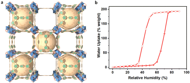 | ||
| Fig. 1 (a) Crystal structure of Super-adsorbent Cr-soc-MOF-1. (b) Water sorption isotherm at 298 K for activated Cr-soc-MOF-1. | ||
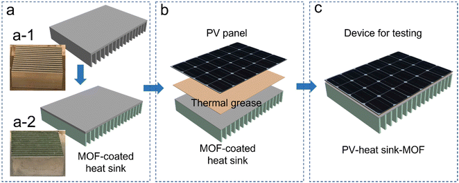
Cr-soc-MOF was synthesized on a large scale based on a modified procedure.24 The purity of the material was confirmed by similarities between the experimental and calculated powder X-ray diffraction (PXRD) patterns (Fig. S2, ESI†). The synthesized Cr-soc-MOF was coated on the surface of the heat fins on a commercialized heat sink with a top dimension of 4.5 × 4.5 cm2via spray coating. The MOF coating was done using a MOF suspension (2.5 mg MOF/1 mL ethanol solvent) that was sonicated for 15 minutes. The suspension was loaded into a 100 mL plastic sprayer and the MOF suspension solution was promptly sprayed onto the heat fins for 30 seconds in each cycle, which were subsequently dried under ambient conditions for 2 minutes. The spraying and drying process was repeated until desired loading weight of the MOF was achieved (see Fig. S1, ESI†). The MOF-coated heat sink exhibited very good distribution and adhesion to the heat fins as revealed by the scanning electron microscopy images (Fig. 3). The MOF-coated heat sink was directly attached to the backside of a 5.0 × 5.0 cm2 commercialized PV panel (SUNTHING GOOD Co. Ltd) that was pasted with thermal grease to ensure close contact and reduce heat resistance across the boundaries between the PV panel and heat sink (Fig. 2b) and assembled with the device for testing (Fig. 2c).
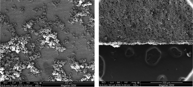 | ||
| Fig. 3 Top-view SEM images of the Cr-soc-MOF-1 particles as-synthesized (left) and after the spray coating process on the heat fins (right). | ||
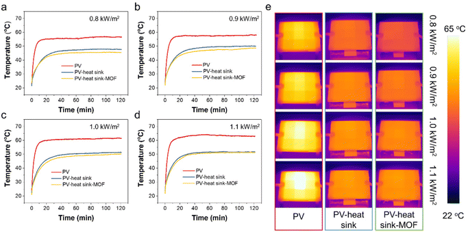
The equilibrium surface temperature of the PV panel at different sunlight intensities is displayed in Fig. 4a–d. As seen, when without any cooling measurements under 0.8, 0.9, 1.0, and 1.1 kW m−2 sunlight irradiation, the PV temperatures were measured to be 56.7, 58.2, 61.5, and 63.1 °C, respectively. When a heat sink was applied, the surface temperature of the PV panel could be reduced by ∼8.5–11.5 °C, which could be attributed to the strengthened heat dissipation process through the significantly enlarged cooling surface area of the heat sink. As a proof-of-concept, when the heat sink was coated with a layer of MOF, the PV temperatures could be further reduced by 2.3, 2.2, 1.6, and 1.1 °C, respectively, which was owing to the evaporative cooling process of water in the MOF layer. Fig. 4e displays the IR images of the PV panel under different test conditions. Clear contrast differences could be observed across the sunlight intensities of 0.8–1.1 kW m−2 and under different cooling configurations such as without cooling, heat sink cooling, and Cr-soc-MOF-1-coated heat sink cooling, demonstrating their distinctive temperature differences.
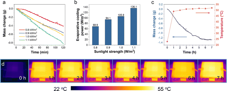
The amount of water evaporated for cooling during the test was determined by the mass change (profiled in Fig. 5a) of the prototype device with the Cr-soc-MOF-1-coated heat sink. The slope of the mass change curves and the final weight loss reflected the water evaporation rate during the test, which highly depended on the incident sunlight intensity. During the 120-min test, the mass changes due to water evaporation at 0.8, 0.9, 1.0, and 1.1 kW m−2 sunlight intensities were 0.41, 0.56, 0.63, and 0.81 g, respectively. The averaged evaporative cooling power provided by the Cr-soc-MOF-1 layer was calculated based on eqn (1):
 | (1) |
The PV cooling test performed under standard illumination at the absolute air mass of 1.5 (AM 1.5) and at 1.0 kW m−2 sunlight intensity was further extended to 7 hours to test the durability of the cooling layer within each working cycle (Fig. 5c). As seen, the mass change curve at the first 4 hours shows a nearly linear relationship along with time elapse, with the evaporated water weighing 1.1 g. Then the slope of the mass change curve drastically decreased and plateaued after approximately 2 extra hours of test. The rapid increase of the temperature in the first 1 h is mainly due to the heat accumulation at the surface of the PV panel before the balance between heat generation and heat dissipation is achieved. With increase in the panel temperature, the cooling power of heat radiation, convection, and the evaporative cooling power by water desorption of the water-saturated MOFs are enhanced, and thus showing a mitigated temperature increase rate. The final mass change was 1.3 g, and the plateaued curve indicated the exhaustion of adsorbed water in the Cr-soc-MOF-1 cooling layer. The temperature change profile displays a huge jump within the first hour from a room temperature of ∼22.5 °C to ∼48.5 °C and then a slow increase to 51.4 °C until 6 hours of test. The final temperature was observed to be 52 °C at the 7th hour, showing a 0.6 °C increase after the exhaustion of water in the Cr-soc-MOF-1 cooling layer. Fig. 4d shows the IR images of the PV panel at different time nodes and their contrast change indicates the inclining of the PV panel surface temperature.
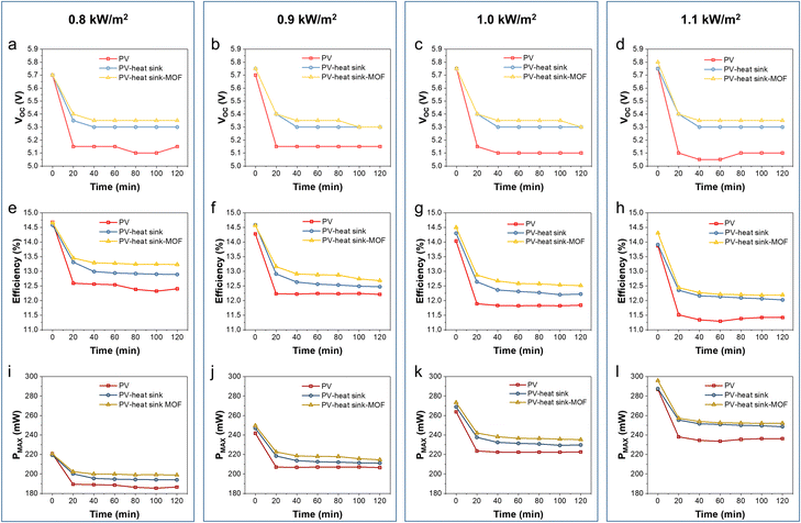
The characteristics of the PV panel during the test, including Voc, efficiency, and Pmax, were calculated from the I–V curves obtained using a Keithley 2400 source meter under different solar strengths and device configurations (Fig. 5). The Voc of the pristine PV panel without cooling was quickly dropped from 5.7–5.75 V to 5.05–5.15 V within the first 20 min at different sunlight intensities. When the heat sink was applied, the Voc changed from 5.7–5.75 V to 5.3–5.35 V within the first 20 min and remained constant at around 5.3 V until the end of the test. When the Cr-soc-MOF-1-coated heat sink was applied, the Voc drop was further delayed, and the equilibrium Voc was ∼0.05 V higher than that of the heat sink without the coating and ∼0.25–0.3 V higher than that of the pristine PV panel, indicating the strengthened cooling effect due to the MOF coating (Fig. 6a–d).
Similarly, the efficiency of the PV panel shows a similar trend to that of the Voc change. The PV panel cooled by the MOF-coated heat sink demonstrated the highest efficiency, followed by the PV panel cooled by a pristine heat sink and then the pristine PV panel without any cooling (Fig. 6e–h). The equilibrium efficiencies at 0.8, 0.9, 1.0, and 1.1 kW m−2 sunlight intensities were 12.3%, 12.2%, 11.8%, and 11.3% for pristine PV, 12.9%, 12.5%, 12.3%, and 12.0% for the PV panel cooled by the heat sink, and 13.2%, 12.9%, 12.6%, and 12.2% for the PV panel cooled by the Cr-soc-MOF-coated heat sink, respectively. It should be mentioned that the original efficiency of the PV panel should be ∼14.8%, and the initial efficiency differences of the PV panel at different sunlight intensities among the three different device configurations were because of the heating effect of the PV panel during its first I–V curve collection under sunlight irradiation.
The Pmax, which serves as the indicator of the electricity generation ability of the PV panels at an optimized load, is also compared in this work (Fig. 6i–l). At the sunlight intensities of 0.8, 0.9, 1.0, and 1.1 kW m−2, the Pmax of the pristine PV panel without cooling rapidly dropped from 219.3, 241.7, 263.8, and 286.9 mW to 185.3, 207.0, 221.4, and 237.5 mW, respectively. The PV panel cooled with the heat sink showed a delayed Pmax decline from 220.6, 246.9, 268.8, and 287.6 mW to 193.9, 211.1, 229.4, and 249.5 mW, respectively. For the PV panel cooled with the Cr-soc-MOF-coated heat sink, the Pmax slowly dropped from 220.7 to 199.2 mW (0.8 kW m−2), 249.6 to 220.1 mW (0.9 kW m−2), 273.3 to 235.2 mW (1.0 kW m−2), and 295.8 to 251.8 mW (1.1 kW m−2), showing the highest Pmax, among others. The Pmax increments were estimated to be ∼7.5, 6.3, 6.2, and 6.0%, respectively. Thus, the Cr-soc-MOF coating can further strengthen the heat dissipation process during the PV panel cooling, thereby promoting the performance of the PV panel at different sunlight intensities.
The first data point of the PV panel cooled by the Cr-soc-MOF-coated heat sink in both efficiency and Pmax displays a distinctive higher value at 1.0 and 1.1 kW m−2 sunlight intensity, indicating a delayed thermal-induced heating effect of the PV panel under strong sunlight irradiation. Notably, even though the evaporative cooling power was calculated to be the highest among others at 1.1 kW m−2, both the efficiency and Pmax observed for the Cr-soc-MOF-coated heat sink batch were close to those of the pristine heat sink batch with less than 2% of enhancement in both cases. This is because the waste heat generated by the PV panel at high sunlight intensity induces a stronger thermal effect, which facilitates the evaporation of water from the MOF layer, reflected as the rapid mass change in the referred test (Fig. 5a). However, upon the loss of water, a higher temperature is required to further remove the residual water inside the MOF that has a stronger affinity, and thus the equilibrium MOF temperature increases, leading to a reduced efficiency and Pmax of the attached PV panel due to high temperature. Based on the observed Voc, efficiency, and Pmax under different test conditions, it is clear that the cooling strategies by using either the heat sink or the heat sink coated with MOFs are more effective at a sunlight intensity of 1.1 kW m−2, with the MOF-coating strategy successfully enhancing PV panel performance compared to the pristine heat sink. Such a phenomenon indicates that appropriate cooling under strong sunlight irradiation is necessary, further demonstrating the effectiveness of the MOF coating in strengthening PV panel performance. It is also worth to mention that the structural stability of the material is completely maintained after these tests, as confirmed by PXRD (Fig. S3, ESI†). Furthermore, a comparison of electricity generation improvement using AWH-based cooling materials is summarized in Table S1, ESI.†
In the case of a Cr-soc-MOF-coated heat sink, both the heat and mass transfer processes are considered the determining factors of the evaporation of water from the MOF layer. Since the conductive heat transfer is insignificant due to the small temperature differences between the PV panel or MOF layer surfaces and the surrounding ambient, it is not considered in the modeling process. The heat balance in the model is described as follows:
| Pin = Prad,PV + Pcon,PV + Prad,MOF + Pcon,MOF + ΔHvap·fevap | (2) |
| Prad = Aεσ(Ts4 − Tamb4) | (3) |
 | (4) |
The MOF layer is considered as a porous medium and the total amount of water in the MOF layer (Wtotal) can be expressed as:
| Wtotal = φpslρl + φpsgρgωv | (5) |
where Mv is the molar weight of water vapor (g mol−1), RH is the relative humidity (%), and Csat(T) is the saturated water concentration (mol m−3) at temperature T. The time-dependent fevap can be expressed as:
| fevap + ρgug·∇ωv + ∇gw + ul·∇ρl + ∇glc = 0 | (6) |
The convection of water vapor is governed by the total pressure gradient within the flow field ug and is calculated using the Brinkman equation. gw is defined as the binary diffusion of dry air and water vapor in the gaseous phase:
| gw = −ρgD∇ωv | (7) |
The water velocity ul (m s−1) is calculated using Darcy's law:
 | (8) |
The capillary transportation of liquid water glc is defined as:
 | (9) |
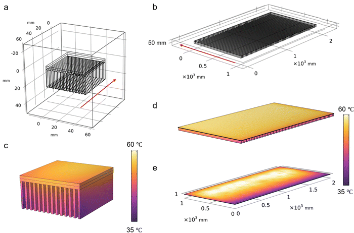
In the first place, a small-scale cooling model was executed with the defined working conditions the same as the lab conditions under which the PV panel-cooling test was performed. The calculation results indicated that the temperature at the equilibrium state is close to the experimental data, which demonstrated the accuracy of the model (Fig. 7a and c). Then, the model dimension was further scaled up to 1 × 2 m2 to predict the cooling effect using the same strategy (Fig. 7b). The wind speed was assumed to be 1 m s−1 and the ambient temperature was set to 30 °C. The Pin was found to be 1600 W, which is equal to 800 W m−2 based on the assumption that 20% of the total incident solar energy is converted to electricity or reflected at 1000 W m−2 sunlight intensity. As seen in Fig. 7d, the equilibrium temperature is calculated to be ∼52 °C, which is slightly higher than that of the small scale (i.e., 48 °C) due to the reduced wind speed across the larger dimension beneath the PV panel. However, this temperature is still much lower than that of the pristine PV panel simulated under the same conditions (i.e., 61 °C, Fig. 7e). The simulation results successfully demonstrated the great potential of the cooling strategy on the enlarged scale, indicating that it provides a possible solution to solve the industrial cooling demands in a sustainable manner.
In conclusion, this work introduces a new AWH-based PV panel cooling strategy based on water vapor sorption using MOFs that can be easily applied on both the deployed and the new PV panels. In this study we have deployed the super-adsorbent Cr-soc-MOF-1 in a sorption based atmospheric water harvester photovoltaic cooling system. The results demonstrate that the AWH-based cooling component can provide 68.9–136.1 W m−2 cooling power, and the temperature of the PV panel can be reduced by ∼10.6–12.6 °C under 0.8–1.1 kW m−2 sunlight irradiation. Markedly, the integrated system demonstrates an increase in electricity generation of up to 7.5%. The experimental and simulation results indicate that it is a promising approach to fulfill the cooling demand in the PV industry with broad adaptability.
Abbreviations
| PV | Photovoltaic |
| AWH-EC | Atmospheric water harvesting-based evaporative cooling. |
Author contributions
The manuscript was written through contributions of all authors. All authors have given approval to the final version of the manuscript.Conflicts of interest
There are no conflicts to declare.Acknowledgements
The authors acknowledge the King Abdullah University of Science and Technology for funding this project.References
- Global solar capacity additions hit 268 GW in 2022, says BNEF, https://www.pv-magazine.com/2022/12/23/global-solar-capacity-additions-hit-268-gw-in-2022-says-bnef/, (accessed 2023 February 7, 2023).
- J.-W. Arnulf, PV Status Report 2019, Report 978-92-76-12608-9, Luxembourg, 2019.
- S. Dubey, J. N. Sarvaiya and B. Seshadri, Energy Procedia, 2013, 33, 311–321 CrossRef.
- E. Skoplaki and J. A. Palyvos, Sol. Energy, 2009, 83, 614–624 CrossRef CAS.
- S. Rühle, Sol. Energy, 2016, 130, 139–147 CrossRef.
- W. Wang, S. Aleid, Y. Shi, C. Zhang, R. Li, M. Wu, S. Zhuo and P. Wang, Joule, 2021, 5, 1873–1887 CrossRef.
- E. Schmidt, Properties of water and steam in SI-units 4 enlarged ed, Springer, Germany, 1989 Search PubMed.
- S. Nižetić, E. Giama and A. M. Papadopoulos, Energy Convers. Manage., 2018, 155, 301–323 CrossRef.
- H. Bahaidarah, A. Subhan, P. Gandhidasan and S. Rehman, Energy, 2013, 59, 445–453 CrossRef.
- Encyclopedia of Climate and Weather, ed. S. Schneider, T. Root and M. Mastrandrea, Oxford University Press, 2 edn, 2011 Search PubMed.
- M. A. Al-Tameemi and V. V. Chukin, J. Atmos Sol. Terr. Phys., 2016, 142, 55–59 CrossRef.
- L. Bengtsson, Environ. Res. Lett., 2010, 5, 025202 CrossRef.
- R. Li, Y. Shi, M. Wu, S. Hong and P. Wang, Nat. Sustainable, 2020, 3, 636–643 CrossRef.
- R. Li, W. Wang, Y. Shi, A. C.-T. Wang and P. Wang, Adv. Mater., 2023, 2209460 CrossRef PubMed.
- O. M. Yaghi, M. O'Keeffe, N. W. Ockwig, H. K. Chae, M. Eddaoudi and J. Kim, Nature, 2003, 423, 705–714 CrossRef CAS PubMed.
- O. M. Yaghi, J. Am. Chem. Soc., 2016, 138, 15507–15509 CrossRef CAS PubMed.
- H. Jiang, D. Alezi and M. Eddaoudi, Nat. Rev. Mater., 2021, 6, 466–487 CrossRef CAS.
- R. G. AbdulHalim, P. M. Bhatt, Y. Belmabkhout, A. Shkurenko, K. Adil, L. J. Barbour and M. Eddaoudi, J. Am. Chem. Soc., 2017, 139, 10715–10722 CrossRef CAS PubMed.
- H. Furukawa, F. Gándara, Y.-B. Zhang, J. Jiang, W. L. Queen, M. R. Hudson and O. M. Yaghi, J. Am. Chem. Soc., 2014, 136, 4369–4381 CrossRef CAS PubMed.
- H. Kim, S. R. Rao, E. A. Kapustin, L. Zhao, S. Yang, O. M. Yaghi and E. N. Wang, Nat. Commun., 2018, 9, 1191 CrossRef PubMed.
- A. J. Rieth, S. Yang, E. N. Wang and M. Dincă, ACS Cent. Sci., 2017, 3, 668–672 CrossRef CAS PubMed.
- E. Gkaniatsou, B. Meng, F. Cui, R. Loonen, F. Nouar, C. Serre and J. Hensen, Nano Energy, 2021, 87, 106224 CrossRef CAS.
- L. Zhu, L. Tian, S. Jiang, L. Han, Y. Liang, Q. Li and S. Chen, Chem. Soc. Rev., 2023, 52, 7389–7460 RSC.
- S. M. Towsif Abtab, D. Alezi, P. M. Bhatt, A. Shkurenko, Y. Belmabkhout, H. Aggarwal, Ł. J. Weseliński, N. Alsadun, U. Samin, M. N. Hedhili and M. Eddaoudi, Chem, 2018, 4, 94–105 CAS.
Footnotes |
| † Electronic supplementary information (ESI) available: Experimental section describing the synthesis, PXRD, PV panel cooling test, and COMSOL model and simulation. See DOI: https://doi.org/10.1039/d3ma00960b |
| ‡ These authors contributed equally. |
| This journal is © The Royal Society of Chemistry 2024 |

