 Open Access Article
Utilization of newly configured carbazole-cyanopyridone structural hybrids towards achieving high-performance cyan fluorescent organic light-emitting diodes†
Vishrutha
K S
a,
Hidayath
Ulla
 be,
Raveendra Kiran
M
 c,
Badekai Ramachandra
Bhat
*a and
Airody Vasudeva
Adhikari
 *ad
*ad
aOrganic Materials Laboratory, Department of Chemistry, National Institute of Technology Karnataka, Surathkal, Mangalore – 575025, India. E-mail: ram@nitk.edu.in; avachem@gmail.com
bDepartment of Physics, Presidency University, Bangalore – 560064, Karnataka, India
cDepartment of Physics, Vignan's Institute of Information Technology, Visakhapatnam – 530049, India
dYenepoya Research Centre, Yenepoya Deemed to be University, Deralakatte, Mangalore – 575 018, India
eInnovation and Translational Research Hub (iTRH), Presidency University, Bangalore – 560064, Karnataka, India
First published on 2nd February 2024
Abstract
Herein, we report the synthesis, characterization, and device fabrication of novel D–A–D (donor–acceptor–donor) type cyanopyridone-based cyan light-emitting organic materials. These small molecules feature a strong electron-donating N-alkylated carbazole unit affixed to a powerful electron-withdrawing cyanopyridone core that is appended with varying secondary donor groups, producing bipolarity in their structures. All the synthesized molecules were well characterized by employing FT-IR, 1H NMR, and 13C NMR spectroscopy, followed by in-depth photophysical, thermal, electrochemical, and electroluminescent studies. Furthermore, we used the density functional theory (DFT) computational approach in the theoretical investigations to gain deeper insights into their electron cloud distributions and structural features. These fluorophores exhibit emission in the 489–510 nm range accompanied by high Stokes shift values, and their TGA data validate the excellent thermal stability (384 °C). As estimated by cyclic voltammetry, the HOMO and LUMO energy levels were found to be 5.35–5.69 eV and 2.92–3.02 eV, respectively, with band gaps of 2.36–2.74 eV. The optical and electrochemical properties of the luminogens have been successfully fine-tuned by varying the auxiliary donors at the carbazole-cyanopyridine hybrids. Electroluminescent studies proved the compatibility of the novel compounds to be an efficient cyan emissive layer with good performance characteristics. Interestingly, amongst the luminophores, Cz-CyP5 bearing a 4-hydroxyphenyl moiety exhibited a maximum current efficiency of 13.16 cd A−1, high power efficiency of 9.85 lm W−1, and good external quantum efficiency of 5.41%.
1. Introduction
In recent years, organic light-emitting diodes (OLEDs) have emerged as a promising option for flexible, large-area, high-resolution displays, and solid-state lighting panels. This is due to their exceptional features, such as high color quality, attractive appearance, high efficiency, improved brightness, lightweight, ease of fabrication, eco-friendliness, and low manufacturing and material costs. These factors make them ideal for smartphones, televisions, and other electronic devices. Since the first invention of OLEDs in 1987 by chemists Tang and Van Slyke,1 this field has appeared as an extensive and active area of research. Consequently, many efforts have been made by academics, industries, and research communities to obtain high-efficiency and long-lifespan wet- and dry-process feasible organic materials. Small molecules are the clear leaders among the organic materials that can be utilized for OLEDs. Their molecular structures are highly ordered, and they can be synthesized with a high degree of reproducibility. Additionally, small molecules are easy to purify and process, both in solution and through vacuum deposition methods. With simple structural modifications, their functional properties can be easily controlled, making them a versatile option for OLEDs.It is mandatory to have red, green, and blue (RGB) as primary colours to achieve white emission in a full-colour display.2–5 Over the past few years, considerable progress has been made in developing highly efficient red and green emitters, and many red and green OLEDs with excellent performance have been reported.6–9 However, the quest for an efficient blue emitter remains challenging compared to its counterparts.10–13 The main obstacle to achieving efficient blue emission lies in materials' inherent characteristics, particularly large optical band gaps. A wide band gap restricts charge delocalization, leading to difficulties in electron injection. A high voltage is required to operate such an emitter in the device. The higher the voltage, the more heat is generated, so the blue emitter possesses low efficiency and a short device lifetime. Consequently, developing blue materials with good EL characteristics and a long lifetime is highly desirable for achieving commercial requirements.
Despite notable advancements, the right choice of organic materials in devices still faces stability, lifetime, and efficiency hurdles.10,11,14,15 Usually, by carefully managing the transport of charge carriers,11,16–18i.e., incorporating proper hole- and electron-transporting layers within the OLED architecture, one can enhance the device's efficiency as one of the approaches. Apart from that, an effective D–A type bipolar material bearing electron-donating (p-type) and electron-accepting (n-type) units can successfully be employed as an emissive layer. The use of bipolar luminogens is preferred due to their remarkably low radiative decay lifetime (τobs < 10 ns), which indicates fast recombination of electrons and holes, leading to more efficient blue light emission in the OLEDs. Moreover, these emitters possess enhanced hole and electron transport properties, promoting efficient charge carrier movement within the device. The bipolar architecture further enables a balanced concentration of holes and electrons in the emitting layer by forming a stable exciton, optimizing the emission efficiency, and minimizing unwanted side reactions in the device. So, it is necessary to design bipolar blue emitters by carefully choosing appropriate electron-donating and accepting units in the molecular structure.
D–A–D type molecules have gained a lot of attention when it comes to creating efficient fluorescent emitters. This is because adding an extra donor can help with carrier injection, improve device charge balance, and increase electroluminescence efficiency.19–22 By varying the donor and acceptor units, it is possible to fine-tune the energies of the HOMO and LUMO, which in turn affects the positions of the absorption and luminescence maxima. These materials are also highly thermally stable and structurally robust upon excitation, making them durable for use in OLED devices. However, these molecular systems can induce charge transfer characteristics, causing a shift in the emission spectrum towards longer wavelengths. This can be unfavorable for designing deep-blue emitters. Therefore, D–A–D type emitters should choose the appropriate donor and acceptor segments to weaken the CT effect.
The most commonly employed electron-donating aryl/heteroaryl units are phenothiazine,23 triphenylamine,24 diphenylamine,25 carbazoles,26 indole,27 and pyrene,28 and electron-acceptor moieties are pyridine,29 quinoxaline,30 benzothiazole,31 and benzoxazole.32 In the present work, a fused tricyclic ring system, viz., a carbazole moiety, has been chosen as a fixed electron-donating scaffold since its derivatives find applications in many optoelectronic devices, for instance, organic thin film transistors (OTFTs), organic solar cells, and OLEDs due to their high thermal stability, emission efficiency, easy chemical functionalization, good film-forming ability, and their potential hole-transporting mobility associated with the electron-donating ability of the N-heterocyclic core ring. Additionally, carbazole, an aromatic and inexpensive starting material with multiple linkage positions on the ring, can bring about a high quantum yield and good thermal, photochemical, and morphological stability for its derivatives.33–36 Furthermore, we have selected an electron-deficient n-type nitrogen-based heterocyclic cyanopyridone moiety as an electron acceptor in the present design because of its thermal stability and variable optical and optoelectronic properties. As the pyridine ring is a highly electron-withdrawing scaffold, introducing it into the D–A architecture causes enhanced electron transporting ability and optical properties. In addition, the presence of the electron-attracting cyano substituent further promotes its electron-transporting nature and produces a compact molecular size, facilitating remarkable resilience to UV radiation. Hence, there is notable interest in the design of carbazole-cyanopyridone hybrid structures with enriched variable donor units to improve their optical and charge transport properties.
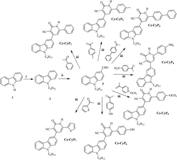
Encouraged by the above-mentioned concepts, we have designed a novel series, Cz-CyP1-7, consisting of seven D–A–D configured carbazole-cyanopyridones bearing varied secondary donor units as potential cyan emitters. In the new design, N-alkylated carbazole acts as the donor, and cyanopyridone is the acceptor for obtaining bipolar transport characteristics in the luminophores. The varied auxiliary donors like phenyl (Cz-CyP1), tolyl (Cz-CyP2), biphenyl (Cz-CyP3), 4-aminophenyl (Cz-CyP4), 4-methoxyphenyl (Cz-CyP5), 4-hydroxyphenyl (Cz-CyP6), and 2-thienyl (Cz-CyP7) moieties have been incorporated to fine-tune their properties. The new fluorophores were successfully synthesized in good yields through simple reaction steps. Spectroscopic methods structurally characterized all of them. Furthermore, their theoretical, photophysical, thermal, electrochemical, electrical, and EL studies were conducted to examine their structure–property relationships. Also, their solvatochromic properties were measured using different solvents to explore their emissive behaviour in solvents with varying polarities. Finally, their EL parameters were investigated by employing them as cyan-color-emitting dopants in solution-processable multilayer OLEDs. All the emitters displayed cyan emission with peaks at 500–550 nm and a band gap of 2.36–2.74 eV. Amongst the fabricated devices, the OLED with Cz-CyP5 showed a notable current efficiency of 13.16 cd A−1, a power efficiency of 9.85 lm W−1, and an external quantum efficiency of 5.41%.
2. Experimental section
2.1. Materials and methods
The starting materials, such as carbazole, bromohexane, aryl ketones, ammonium acetate, and ethyl cyanoacetate, were purchased from Sigma-Aldrich and Spectrochem. The solvents used for the synthesis were distilled before their use. The reaction was carried out under an inert atmosphere, and the TLC technique was used to confirm the completion of the reaction. The synthesized compounds were purified by column chromatography or recrystallization techniques. The structure of the new compounds was confirmed by spectral techniques. 1HNMR spectroscopy was run on a Bruker advanced spectrometer working at a frequency of 400 MHz at room temperature in DMSO-d6 solvent with TMS as an internal standard. The IR spectra were acquired on a Bruker FTIR Alpha spectrophotometer and mass spectra were obtained by using the ACQUITYTM UPLCTM H-Class PLUS Biosystem (electron spray ionization technique) mass spectrometer to confirm the molecular weight of the synthesized compounds. The UV-vis absorption spectra were recorded with the help of the SPECORD S600 Spectrometer. PL emission spectral studies were performed using a Jasco FP 6200 spectrophotometer. Electrochemical properties were measured on an AUTO LAB electrochemical workstation with a three-electrode set-up (i.e., glassy carbon as a working electrode, Ag/AgCl as a reference electrode, and a platinum electrode as a counter electrode). Ferrocene was used as an internal standard for recording cyclic voltammograms. The cyclic voltammetry measurements were recorded in 10−3 M anhydrous acetonitrile solution and 0.1 M tetra-n-butylammonium tetrafluoroborate as a supporting electrolyte at room temperature in an inert condition. Thermogravimetric analysis was carried out in the nitrogen atmosphere over a temperature range of 100–600 °C at a heating rate of 10 °C min−1 on a PerkinElmer TGA 400 Analyzer. The thermal decomposition temperatures of the synthesized fluorophores had a weight loss temperature of 5%. The theoretical calculations were performed using Gaussian 09 software, utilizing the Becke three-parameter exchange function and the Lee–Yang–Parr (B3LYP) exchange–correlation function. The optimized geometry structures were obtained employing the 6-31(d,p) basis set for carbon (C), hydrogen (H), nitrogen (N), and oxygen (O).2.2. Synthetic procedure
The synthesis strategy of the targeted luminophores is shown in Scheme 1. The obtained pure compounds were systematically characterized by FTIR, NMR and Mass spectral analyses.![[thin space (1/6-em)]](https://www.rsc.org/images/entities/char_2009.gif) :
:![[thin space (1/6-em)]](https://www.rsc.org/images/entities/char_2009.gif) ethyl acetate (7
ethyl acetate (7![[thin space (1/6-em)]](https://www.rsc.org/images/entities/char_2009.gif) :
:![[thin space (1/6-em)]](https://www.rsc.org/images/entities/char_2009.gif) 3) to obtain a yellow liquid.
3) to obtain a yellow liquid.
![[thin space (1/6-em)]](https://www.rsc.org/images/entities/char_2009.gif) :
:![[thin space (1/6-em)]](https://www.rsc.org/images/entities/char_2009.gif) 1) as an eluent on silica gel of mesh 200–400. The spectral data are shown in Fig. S1–S28 of the ESI.†
1) as an eluent on silica gel of mesh 200–400. The spectral data are shown in Fig. S1–S28 of the ESI.†
2.3. Structural characterization
![[triple bond, length as m-dash]](https://www.rsc.org/images/entities/char_e002.gif) N), 1633 (C
N), 1633 (C![[double bond, length as m-dash]](https://www.rsc.org/images/entities/char_e001.gif) O), 1491 (Ar-C
O), 1491 (Ar-C![[double bond, length as m-dash]](https://www.rsc.org/images/entities/char_e001.gif) C); 1HNMR (DMSO-d6, 500 MHz): δ 12.72 (s,1H, CONH), 0.98 (s,3H), 1.27 (m,6H), 1.78 (t,2H), 4.45 (t,2H), 6.96 (s,1H), 7.25 (t,1H), 7.50 (m,4H), 7.54 (m,1H), 7.67 (m,1H), 7.77 (m,3H), 8.25 (m,1H), 8.64 (s,1H) 12.72 (s,1H); 13CNMR (DMSO, 125 MHz): δ 175.51, 162.30, 141.07, 131.07, 128.91, 126.43, 122.24, 120.74, 119.43, 109.74; Melting point 170 °C, Yield 50%; Mass (m/z) value for C30H27N3O 445.57, obtained [M-H] 446.22.
C); 1HNMR (DMSO-d6, 500 MHz): δ 12.72 (s,1H, CONH), 0.98 (s,3H), 1.27 (m,6H), 1.78 (t,2H), 4.45 (t,2H), 6.96 (s,1H), 7.25 (t,1H), 7.50 (m,4H), 7.54 (m,1H), 7.67 (m,1H), 7.77 (m,3H), 8.25 (m,1H), 8.64 (s,1H) 12.72 (s,1H); 13CNMR (DMSO, 125 MHz): δ 175.51, 162.30, 141.07, 131.07, 128.91, 126.43, 122.24, 120.74, 119.43, 109.74; Melting point 170 °C, Yield 50%; Mass (m/z) value for C30H27N3O 445.57, obtained [M-H] 446.22.
![[triple bond, length as m-dash]](https://www.rsc.org/images/entities/char_e002.gif) N), 1632.31 (C
N), 1632.31 (C![[double bond, length as m-dash]](https://www.rsc.org/images/entities/char_e001.gif) O) 1503.46 (Ar C
O) 1503.46 (Ar C![[double bond, length as m-dash]](https://www.rsc.org/images/entities/char_e001.gif) C); 1HNMR (DMSO-d6, 500 MHz): δ 0.78 (d,3H), 1.16 (m,8H), 1.77 (t,2H), 1.97 (s,3H), 4.43 (t,2H), 6.93 (s,1H), 7.23 (m,1H), 7.34 (m,1H), 7.48 (m,2H), 5.50 (m,1H), 7.65 (m,1H), 7.75 (m,1H), 7.82 (m,3H), 8.25 (m,2H) 8.60 (s,1H); 13CNMR δ 141.24, 140.58, 133.70, 129.50, 127.62, 126.37, 125.97, 122.22, 121, 119.40, 117.30; Melting point 215 °C; Yield 40%; Mass (m/z) value for C31H29N3O 459.59, obtained [M-H] 460.24.
C); 1HNMR (DMSO-d6, 500 MHz): δ 0.78 (d,3H), 1.16 (m,8H), 1.77 (t,2H), 1.97 (s,3H), 4.43 (t,2H), 6.93 (s,1H), 7.23 (m,1H), 7.34 (m,1H), 7.48 (m,2H), 5.50 (m,1H), 7.65 (m,1H), 7.75 (m,1H), 7.82 (m,3H), 8.25 (m,2H) 8.60 (s,1H); 13CNMR δ 141.24, 140.58, 133.70, 129.50, 127.62, 126.37, 125.97, 122.22, 121, 119.40, 117.30; Melting point 215 °C; Yield 40%; Mass (m/z) value for C31H29N3O 459.59, obtained [M-H] 460.24.
![[triple bond, length as m-dash]](https://www.rsc.org/images/entities/char_e002.gif) N), 1630.25 (C
N), 1630.25 (C![[double bond, length as m-dash]](https://www.rsc.org/images/entities/char_e001.gif) O), 1482.29 (Ar-C
O), 1482.29 (Ar-C![[double bond, length as m-dash]](https://www.rsc.org/images/entities/char_e001.gif) C); 1HNMR (DMSO-d6, 500 Hz): δ 1.31 (d,3H), 1.79 (6H,t), 1.83 (t,2H), 4.49 (d,2H), 7.02 (m,1H), 7.26 (m,1H), 7.30 (m,1H), 7.42 (m,3H), 7.50 (m,3H) 8.05 (m,2H), 8.26 (s,1H), 8.66 (s,1H), 12.7 (s,1H); 13CNMR (DMSO, 125M Hz): δ 143.03, 141.56, 129.57, 128.70, 127.48, 122.74, 121.55, 110.23; Melting point 250 °C; Yield 40%; Mass (m/z) value for C36H25N3O 521.66, obtained [M-H] 522.14.
C); 1HNMR (DMSO-d6, 500 Hz): δ 1.31 (d,3H), 1.79 (6H,t), 1.83 (t,2H), 4.49 (d,2H), 7.02 (m,1H), 7.26 (m,1H), 7.30 (m,1H), 7.42 (m,3H), 7.50 (m,3H) 8.05 (m,2H), 8.26 (s,1H), 8.66 (s,1H), 12.7 (s,1H); 13CNMR (DMSO, 125M Hz): δ 143.03, 141.56, 129.57, 128.70, 127.48, 122.74, 121.55, 110.23; Melting point 250 °C; Yield 40%; Mass (m/z) value for C36H25N3O 521.66, obtained [M-H] 522.14.
![[triple bond, length as m-dash]](https://www.rsc.org/images/entities/char_e002.gif) N), 1597.25 (C
N), 1597.25 (C![[double bond, length as m-dash]](https://www.rsc.org/images/entities/char_e001.gif) O), 1509 (Ar-C
O), 1509 (Ar-C![[double bond, length as m-dash]](https://www.rsc.org/images/entities/char_e001.gif) C); 1HNMR (DMSO-d6, 500 MHz): δ 0.79 (t,3H), 1.23 (6H.d), 178 (d,2H), 4.44 (d,1H), 5.93 (s,1H), 6.77 (m,2H), 7.22 (m,1H), 7.49 (m,1H), 7.76 (m,4H), 8.23 (t,1H), 8.56 (s,1H), 12.22 (s,1H); 13CNMR: δ 163, 160.86, 153.59, 141.40, 129.55, 127.38, 122.66, 121.25, 119.81, 118.35, 113.92, 110.17, 104.11; Melting point 260 °C; Yield 30%; Mass (m/z) value for C30H28N4O 460.58, obtained [M-H] 461.23.
C); 1HNMR (DMSO-d6, 500 MHz): δ 0.79 (t,3H), 1.23 (6H.d), 178 (d,2H), 4.44 (d,1H), 5.93 (s,1H), 6.77 (m,2H), 7.22 (m,1H), 7.49 (m,1H), 7.76 (m,4H), 8.23 (t,1H), 8.56 (s,1H), 12.22 (s,1H); 13CNMR: δ 163, 160.86, 153.59, 141.40, 129.55, 127.38, 122.66, 121.25, 119.81, 118.35, 113.92, 110.17, 104.11; Melting point 260 °C; Yield 30%; Mass (m/z) value for C30H28N4O 460.58, obtained [M-H] 461.23.
![[thin space (1/6-em)]](https://www.rsc.org/images/entities/char_2009.gif) :
:![[thin space (1/6-em)]](https://www.rsc.org/images/entities/char_2009.gif) 2926.14 (Ar C–H), 2217.90 (C
2926.14 (Ar C–H), 2217.90 (C![[triple bond, length as m-dash]](https://www.rsc.org/images/entities/char_e002.gif) N), 1631.09 (C
N), 1631.09 (C![[double bond, length as m-dash]](https://www.rsc.org/images/entities/char_e001.gif) O), 1603 (Ar-C
O), 1603 (Ar-C![[double bond, length as m-dash]](https://www.rsc.org/images/entities/char_e001.gif) C); 1HNMR (DMSO-d6, 500 MHz): δ 0.79 (t,3H), 1.27 (t,8H), 1.79 (s,2H), 3.30 (t,3H), 4.45 (s,2H), 6.90 (m,1H), 7.07 (m,2H), 7.24 (m,1H), 7.49 (m,1H), 7.51 (m,1H), 7.65 (m,1H), 7.75 (m,1H), 7.85 (m,2H), 8.24 (d,1H), 8.60 (s,1H), 12.56 (s,1H); 13CNMR (DMSO, 125 MHz): δ 162.86, 161.07, 141.51, 129.89, 126.89, 122.71, 121.42, 119.89, 117.92, 114.86, 110.21, 109.88; Melting point 200 °C; Yield 40%; Mass (m/z) value for C31H29N3O2 475.59, obtained [M-H] 476.22.
C); 1HNMR (DMSO-d6, 500 MHz): δ 0.79 (t,3H), 1.27 (t,8H), 1.79 (s,2H), 3.30 (t,3H), 4.45 (s,2H), 6.90 (m,1H), 7.07 (m,2H), 7.24 (m,1H), 7.49 (m,1H), 7.51 (m,1H), 7.65 (m,1H), 7.75 (m,1H), 7.85 (m,2H), 8.24 (d,1H), 8.60 (s,1H), 12.56 (s,1H); 13CNMR (DMSO, 125 MHz): δ 162.86, 161.07, 141.51, 129.89, 126.89, 122.71, 121.42, 119.89, 117.92, 114.86, 110.21, 109.88; Melting point 200 °C; Yield 40%; Mass (m/z) value for C31H29N3O2 475.59, obtained [M-H] 476.22.
![[triple bond, length as m-dash]](https://www.rsc.org/images/entities/char_e002.gif) N), 1625.39 (C
N), 1625.39 (C![[double bond, length as m-dash]](https://www.rsc.org/images/entities/char_e001.gif) O), 1597 (Ar-C
O), 1597 (Ar-C![[double bond, length as m-dash]](https://www.rsc.org/images/entities/char_e001.gif) C); 1HNMR (DMSO-d6, 500 MHz): δ 0.98 (s,3H), 1.23 (q,3H), 1.29 (m,7H), 1.78 (t,2H), 445 (t,2H), 6.91 (m,2H), 7.25 (m,1H), 7.50 (m,1H), 7.67 (m,1H), 7.71 (m,3H), 8.25 (m,1H), 8.67 (m,1H), 10.24 (s,1H), 12.50 (s,1H); 13CNMR (DMSO-d6, 125 MHz): δ 162.88, 161.70, 141.48, 130, 127.05, 126.88, 123.24, 121.39, 119.87, 118.02, 116.22, 110.20; Melting point 250 °C; Yield 50%; Mass (m/z) for C30H27N3O2 461.57, obtained [M-H] 462.20.
C); 1HNMR (DMSO-d6, 500 MHz): δ 0.98 (s,3H), 1.23 (q,3H), 1.29 (m,7H), 1.78 (t,2H), 445 (t,2H), 6.91 (m,2H), 7.25 (m,1H), 7.50 (m,1H), 7.67 (m,1H), 7.71 (m,3H), 8.25 (m,1H), 8.67 (m,1H), 10.24 (s,1H), 12.50 (s,1H); 13CNMR (DMSO-d6, 125 MHz): δ 162.88, 161.70, 141.48, 130, 127.05, 126.88, 123.24, 121.39, 119.87, 118.02, 116.22, 110.20; Melting point 250 °C; Yield 50%; Mass (m/z) for C30H27N3O2 461.57, obtained [M-H] 462.20.
![[thin space (1/6-em)]](https://www.rsc.org/images/entities/char_2009.gif) :
:![[thin space (1/6-em)]](https://www.rsc.org/images/entities/char_2009.gif) 2952 (Ar C-H), 2200 (C
2952 (Ar C-H), 2200 (C![[triple bond, length as m-dash]](https://www.rsc.org/images/entities/char_e002.gif) N), 1635.15 (C
N), 1635.15 (C![[double bond, length as m-dash]](https://www.rsc.org/images/entities/char_e001.gif) O), 1594.51 (Ar-C
O), 1594.51 (Ar-C![[double bond, length as m-dash]](https://www.rsc.org/images/entities/char_e001.gif) C); 1HNMR (DMSO-d6, 500 MHz): δ 0.83 (s,3H), 1.23 (t,8H), 1.78 (d,2H), 4.46 (s,2H), 7.25 (m,2H), 7.27 (m,1H), 7.50 (m,1H), 7.66 (m,3H), 8.09 (m,1H), 8.10 (m,1H), 8.25 (m,1H), 12.73 (s,1H); 13CNMR: δ 141.45, 131.73, 129.41, 126.91, 122.71, 121.31, 119.88, 117.51, 110.20; Melting point 160 °C; Yield 30%; Mass (m/z) for C28H25N3OS 451.59, obtained [M-H] 452.17.
C); 1HNMR (DMSO-d6, 500 MHz): δ 0.83 (s,3H), 1.23 (t,8H), 1.78 (d,2H), 4.46 (s,2H), 7.25 (m,2H), 7.27 (m,1H), 7.50 (m,1H), 7.66 (m,3H), 8.09 (m,1H), 8.10 (m,1H), 8.25 (m,1H), 12.73 (s,1H); 13CNMR: δ 141.45, 131.73, 129.41, 126.91, 122.71, 121.31, 119.88, 117.51, 110.20; Melting point 160 °C; Yield 30%; Mass (m/z) for C28H25N3OS 451.59, obtained [M-H] 452.17.
3. Results and discussion
3.1. Computational calculations
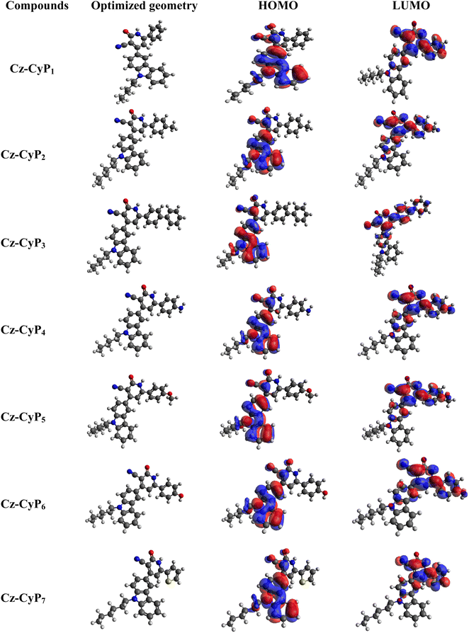
The investigation of the electron distribution in the molecules was carried out through DFT analysis, employing the Gaussian 09 software with the BLYP-16-31(G) level. The electron distributions within the HOMO (highest occupied molecular orbital) and LUMO (lowest unoccupied molecular orbital) levels of all the molecules are depicted in Fig. 1, and their corresponding data are tabulated in Table 3. The investigation outcomes unveiled a distinct localization of the HOMO primarily on the carbazole unit, whereas the LUMO exhibited dispersion across the central electron-withdrawing cyanopyridone moiety. Notably, the absence of orbital mixing strongly implies that the emission of fluorophores predominantly arises from intramolecular charge transfer (ICT) processes. This observation is further substantiated by the noticeable positive solvatochromic shift observed. As calculated using DFT calculations, the band gap values are higher than the experimentally determined optical band gaps. This discrepancy can be attributed to various factors, such as the influence of the polarity of the solvents, counter ions, pH, temperature, and ionic strength, as well as the structural variations of the electrodes during the electron transfer process.3.2. Optical properties
Absorption and emission spectra of the newly synthesized fluorophores in DCM solution and the thin film state were measured to study their photophysical properties. The spectra are shown in Fig. 2, and the corresponding photophysical data are tabulated in Table 1. The synthesized molecules showed a good quantum yield in the range of 10-40% in the thin film state. The absorption spectra of Cz-CyP1-7 displayed distinct absorption bands attributed to π–π* transition and ICT interactions between the donor and acceptor units. The two prominent absorption bands were observed at 270 and 236 nm; the former is due to the π–π* electronic transition occurring within the carbazole scaffold itself, and the latter is owing to the presence of the secondary donor groups. The phenyl rings with electron-donating auxochromic groups like hydroxy, amino, methoxy, and methyl strengthen the auxiliary behaviour of the secondary electron-donating moiety. Thus, 4-phenyl, 4-tolyl, 4-biphenyl, 4-aminophenyl, 4-methoxyphenyl, 4-hydroxyphenyl, and 2-thienyl moieties were the auxiliary secondary donors. In addition, comparatively, a weaker absorption peak was detected in the 374 to 391 nm range. The bands at 374 (Cz-CyP1), 376 (Cz-CyP2), 383 (Cz-CyP3), 391 (Cz-CyP4), 380 (Cz-CyP5), 377 (Cz-CyP6), and 391 nm (Cz-CyP7) correspond to ICT transition from the aryl/heteroaryl group to the cyanopyridone core. The auxochromic groups in the secondary donors significantly impact the dye's absorption and emission. Interestingly, the molecules containing amino and thienyl substituents display a positive shift in the ICT transition towards a longer wavelength (red region), suggesting that the additional donors play a significant role in facilitating the ICT process. The optical band gap of the dyes was determined from the solution state absorption spectra and the values were found to be 2.85 (Cz-CyP1), 2.83 (Cz-CyP2), 2.84 (Cz-CyP3), 2.78 (Cz-CyP4) 2.89 (Cz-CyP5), 2.93 (Cz-CyP6) and 2.79 eV (Cz-CyP7).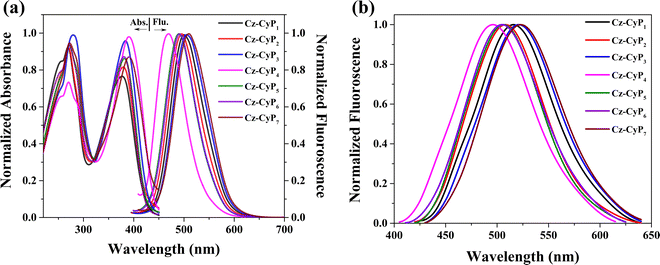 | ||
| Fig. 2 (a) Absorbance spectra, (b) fluorescence spectra in solution and (c) fluorescence spectra in the thin film state of Cz-CyP1-7. | ||
| Compound | λ A (nm) | λ E (FWHM) (nm) | λ E (FWHM) (nm) | E g opt (eV) | Δλ (cm−1) | ε (M−1 cm−1) at λA (nm) | Φ F |
|---|---|---|---|---|---|---|---|
| a Recorded in DCM (10−5 M) at room temperature. b Recorded in a solid thin-film state. λ A: Absorption maxima.λE: Emission maxima. FWHM: Full width at half-maximum.Egopt: Optical band gap.Δλ: Stokes shift.ΦF: Fluorescence quantum yields. | |||||||
| Cz-CyP1 | 236,270,374 | 500(77) | 516(87) | 2.85 | 6737 | 69![[thin space (1/6-em)]](https://www.rsc.org/images/entities/char_2009.gif) 400 400 |
0.36 |
| Cz-CyP2 | 234,270,376 | 496(79) | 508(85) | 2.83 | 6434 | 75![[thin space (1/6-em)]](https://www.rsc.org/images/entities/char_2009.gif) 636 636 |
0.41 |
| Cz-CyP3 | 236,275,383 | 505(86) | 521(88) | 2.84 | 6307 | 71![[thin space (1/6-em)]](https://www.rsc.org/images/entities/char_2009.gif) 870 870 |
0.63 |
| Cz-CyP4 | 236,269,391 | 468(67) | 496(89) | 2.78 | 4207 | 87![[thin space (1/6-em)]](https://www.rsc.org/images/entities/char_2009.gif) 567 567 |
0.24 |
| Cz-CyP5 | 236,269,380 | 489(79) | 506(83) | 2.89 | 5865 | 79![[thin space (1/6-em)]](https://www.rsc.org/images/entities/char_2009.gif) 060 060 |
0.58 |
| Cz-CyP6 | 236,271,377 | 489(75) | 503(87) | 2.93 | 6075 | 81![[thin space (1/6-em)]](https://www.rsc.org/images/entities/char_2009.gif) 075 075 |
0.31 |
| Cz-CyP7 | 236,271,391 | 510(87) | 523(88) | 2.79 | 5967 | 66![[thin space (1/6-em)]](https://www.rsc.org/images/entities/char_2009.gif) 808 808 |
0.29 |
The emission spectra were obtained by exciting the molecules at a wavelength corresponding to their maximum absorption in a 10−5 M solution of DCM and a solid thin film state. All the molecules exhibited a solitary emission peak within the 468 to 510 nm range. The compounds Cz-CyP3 and Cz-CyP7 showed the highest emission intensity due to the significant electron-donating characteristics of their secondary groups. The Stokes shift values of Cz-CyP1-7 were calculated using eqn (1).
 | (1) |
The electronic structure determines the magnitude of the Stokes shift and is an essential luminous characteristic. It gives information about the difference in the structure and properties of the fluorophores between the ground and excited states. The calculated values for Cz-CyP1-7 were 6737, 6434, 6307, 4207, 5865, 6075, and 5967 cm−1, respectively.
Generally, the interaction of a molecule with solvents of various polarities is determined by solvatochromic studies. For the analysis, Cz-CyP1-7 were dissolved in solvents like toluene, acetone, ethyl acetate, acetonitrile, and ethanol of different polarities, and their absorption and emission spectra were recorded (Table 2). Their absorption spectral analysis indicated that the polarity of the solvent had no discernible impact on the molecule, suggesting a non-polar ground state nature. However, the emission spectra exhibited a notable redshift, implying an interaction between the solvents and the molecule's ground state. The observed redshift emission in polar solvents can be attributed to a diminished energy gap between the compound's ground and excited states. This reduced energy gap arises from the presence of the donor and acceptor moieties involved in conjugation, resulting in the electron cloud being delocalized towards the acceptor side from the donor side.
| Fluorophore | Toluene | Ethyl acetate | Acetone | Ethanol | Acetonitrile | ||||||||||
|---|---|---|---|---|---|---|---|---|---|---|---|---|---|---|---|
| λ A | λ E | Δλ | λ A | λ E | Δλ | λ A | λ E | Δλ | λ A | λ E | Δλ | λ A | λ E | Δλ | |
| λ A: Absorption maxima in nm; λE: Emission maxima in nm; Δλ: Stokes shift in cm−1. | |||||||||||||||
| Cz-CyP1 | 372 | 457 | 4999 | 367 | 486 | 6671 | 368 | 507 | 7450 | 369 | 448 | 4778 | 369 | 523 | 7979 |
| Cz-CyP2 | 373 | 451 | 4636 | 369 | 480 | 6266 | 369 | 500 | 7100 | 371 | 513 | 7461 | 372 | 522 | 7724 |
| Cz-CyP3 | 381 | 465 | 4741 | 374 | 491 | 2871 | 374 | 510 | 7130 | 377 | 515 | 7107 | 380 | 531 | 7483 |
| Cz-CyP4 | 384 | 461 | 4349 | 391 | 469 | 4253 | 401 | 485 | 4319 | 393 | 510 | 5837 | 404 | 503 | 4871 |
| Cz-CyP5 | 375 | 443 | 4093 | 371 | 454 | 4927 | 373 | 493 | 6525 | 374 | 502 | 6817 | 371 | 523 | 7833 |
| Cz-CyP6 | 369 | 448 | 4778 | 370 | 445 | 6535 | 372 | 488 | 6389 | 374 | 505 | 6935 | 379 | 510 | 6777 |
| Cz-CyP7 | 384 | 456 | 4111 | 370 | 456 | 5097 | 374 | 491 | 6371 | 381 | 469 | 4924 | 386 | 531 | 7074 |
Consequently, an internal charge-transfer state and the locally excited state are established. The enhanced polarity of polar solvents favours the formation of the internal charge-transfer state. Thus, the difference in energy between polar solvents' ground and excited states diminishes, leading to a red-shifted emission. To further describe the solvatochromic behaviour of the fluorophore, a Lippert–Mataga plot was constructed, correlating the Stokes shift (Δγ) with the orientation polarizability (Δf). Δf is defined as per eqn (2).
 | (2) |
The orientation polarizability describes Stokes shift in terms of change in the dipole moment of the fluorophore and dependence of the energy of the dipole on the dielectric constant (ε) and refractive index of the solvent (n). In the Lippert–Mataga plot, the linear relation between the polarity of the solvent and Stokes shift helps to determine the ICT in the fluorescent compounds. The plot for these compounds pictured the above-mentioned emission properties of the molecules. It gave a proper idea about the presence of the single excited state and the higher dipole moment of the excited state, confirming the ICT behaviour.
3.3. Electrochemical properties
Electrochemical measurements were performed using cyclic voltammetry (CV) to evaluate the electrochemical characteristics of Cz-CyP1-7. These measurements determined the dyes’ electrochemical band gap and molecular energy levels. The CV experiments were conducted at a scan rate of 100 mV s−1 using a three-electrode system. The working electrode was a glassy carbon electrode, the reference electrode was Ag/AgCl, and a platinum plate was the auxiliary electrode. An inert electrolyte, specifically 0.1 M tetra-n-butylammonium tetrafluoroborate, was used throughout the study. The measurements revealed that the fluorophores undergo both reversible oxidation and reduction processes, resulting in the formation of stable cation and anion radicals. This suggests that the fluorophore possesses bipolar transporting properties. The presence of an electron-donating group at both ends of the cyanopyridone core has led to the observation of two oxidation potential peaks in the cyclic voltammograms. Here, the second oxidation potential was used to calculate the HOMO. The HOMO was obtained using eqn (3).| EHOMO = −(Eoxdonset + 4.8 eV) | (3) |
From the calculations, the HOMO levels of the fluorophores were found to be in the range of 5.697 to 5.356 eV. These results indicate that the molecules possess a low energy barrier between the HOMO and hole-transporting materials, which results in the effective hole injection into the emissive layer. The electron-withdrawing nature of the cyano and carbonyl groups of the cyanopyridone core influences the two reduction potential peaks in the CV curves. The LUMO levels of the molecules were calculated using eqn (4).
| ELUMO = − (Eredonset + 4.8 eV) | (4) |
The obtained values are in the range of 2.926 to 3.020 eV (Table 3). Finally, the electrochemical band gap of the molecules was calculated by taking the differences of the HOMO and LUMO energy levels, which were found to be 2.49, 2.36, 2.74, 2.43, 2.39, 2.45, and 2.41 eV for Cz-CyP1-7, respectively.
| Dyes | E ox onset (V) | E red onset (V) | E HOMO (eV) | E LUMO (eV) | E g CV (eV) | E HOMO (eV) | E LUMO | E g (eV) | T d (°C)d |
|---|---|---|---|---|---|---|---|---|---|
| CV measurements | DFT calculation | ||||||||
| a In anhydrous acetonitrile solution. b E HOMO= -e[EOXonset+ 4.8 V]. c E LUMO = -e[Eredonset+ 4.8 V]. d T d: Decomposition temperature corresponding to 5% weight loss. | |||||||||
| Cz-CyP1 | 1.040 | −1.458 | −5.44 | −2.94 | 2.50 | −5.57 | −2.10 | 3.47 | 384 |
| Cz-CyP2 | 0.982 | −1.379 | −5.38 | −3.02 | 2.36 | −5.54 | −2.04 | 3.50 | 334 |
| Cz-CyP3 | 1.297 | −1.451 | −5.70 | −2.95 | 2.75 | −5.56 | −2.16 | 3.39 | 153 |
| Cz-CyP4 | 0.975 | −1.458 | −5.38 | −2.94 | 2.44 | −5.46 | −1.85 | 3.61 | 245 |
| Cz-CyP5 | 0.956 | −1.437 | −5.36 | −2.93 | 2.43 | −5.52 | −1.95 | 3.57 | 226 |
| Cz-CyP6 | 0.988 | −1.470 | −5.39 | −2.93 | 2.46 | −5.54 | −1.98 | 3.55 | 161 |
| Cz-CyP7 | 0.982 | −1.431 | −5.38 | −2.97 | 2.41 | −5.57 | −2.28 | 3.29 | 378 |
3.4. Thermal properties
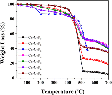
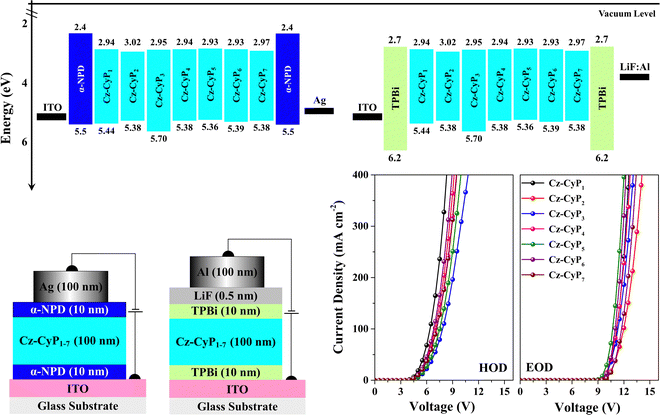
The generation of significant Joule heat due to high current density during the device operation poses a considerable challenge. Therefore, ensuring the thermal stability of the organic material is crucial when utilizing it in OLED device applications. Having excellent thermal stability, the dyes play a vital role in forming a uniform amorphous film during evaporation, thereby enhancing the OLEDs’ long-term efficiency and stability. Thermogravimetric analysis (TGA) was employed to assess the thermal stability of the newly synthesized molecules. The measurements were conducted under a nitrogen atmosphere with a 10 °C min−1 heating rate, as depicted in Fig. 3. The obtained TGA data revealed that all the molecules exhibited impressive thermal stability (Table 3). The decomposition temperature was determined to be as follows: 384 °C (Cz-CyP1), 334 °C (Cz-CyP2), 153 °C (Cz-CyP3), 245 °C (Cz-CyP4), 226 °C (Cz-CyP5), 161 °C (Cz-CyP6), and 378 °C (Cz-CyP7). Notably, a rigid cyanopyridone scaffold in the molecules imparted additional thermal stability owing to its hydrogen bonding properties. Notably, a few of the fluorophores demonstrated a slight weight loss at around 150 °C, which could be attributed to the presence of volatile impurities or residual moisture in the materials rather than the intrinsic weight loss of the compounds.3.5. Electroluminescence properties
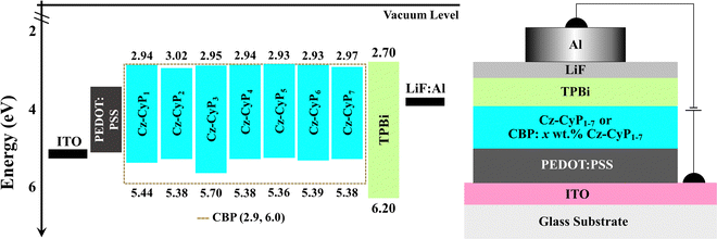
Single-carrier devices were used to evaluate the carrier-transport capabilities of the synthesized dyes Cz-CyP1-7. The device architectures of the hole-only-devices (HODs) and electron-only-devices (EODs) are ITO/α-NPD (10 nm)/Cz-CyP1-7 (50 nm)/α-NPD (10 nm)/Ag (100 nm) and ITO/TPBi (10 nm)/Cz-CyP1-7 (50 nm)/TPBi (10 nm)/LiF (0.5 nm)/Al (100 nm), respectively (Fig. 4). Here, ITO (indium tin oxide) was employed as an anode. α-NPD (4,4′-bis[N-(1-naphthyl)-N-phenyl-L-amino]-biphenyl) was used both as a hole-transporting layer (HTL) and electron-blocking layer (EBL) in HODs.37 In EODs, TPBi (2,2′,2′′-(1,3,5-benzinetriyl)-tris(1-phenyl-1-H-benzimidazole)) was used as both an electron-transporting layer (ETL) and hole-blocking layer (HBL) to facilitate electron-only current.38 Additionally, LiF (lithium fluoride) and Al (aluminium) were employed as an electron-injection layer (EIL) and cathode, respectively. The current density–voltage (J–V) characteristics of the fabricated HODs and EODs are shown in Fig. 4. The hole and electron current densities increased with the voltage and showed a comparable trend. As shown in Fig. 4, distinct variations can be seen in the J–V characteristics of the HODs and EODs. When the voltage is increased, the current in the HODs responds more quickly than in the EODs. This is consistent with the observation that the mobility of holes is often more significant than that of electrons in organic semiconductors.39 Among these seven dyes, Cz-CyP1 has the best hole-transporting property, and Cz-CyP5 has the best electron-transporting property. The results show that all dyes have much greater hole-transport capabilities than electron-transport capabilities. The studies also show that OLED devices using Cz-CyP1-7 can efficiently balance holes and electrons, leading to balanced exciton formation and recombination in the emitting layer and, ultimately, good device performance.The high-intensity emission and favourable HOMO–LUMO energies of new Cz-CyP1-7 dyes prompted us to investigate their use in OLEDs. Thus, solution-processed multilayer device architectures were used to test the adaptability of the dyes Cz-CyP1-7 as potential cyan emitters in OLEDs. Fig. 5 displays the schematic of the solution-processed OLEDs and molecular energy level alignments. To avoid aggregation-induced concentration quenching, ensure efficient charge trapping by suitable HOMO and LUMO energy, and achieve effective charge-carrier balance in OLEDs,39,40 we used 3 wt% of dyes as dopants in the wide energy host material, CBP (4,4′-bis(N-carbazolyl)-1,1′-biphenyl).
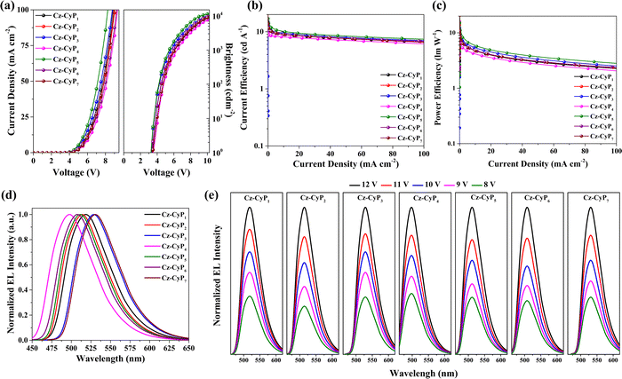
Low dopant concentrations allowed easy charge transmission and prevented concentration quenching, ensuring EL colour purity.38,39 ITO (120 nm)/PEDOT: PSS (35 nm)/CBP: 3 wt% Cz-CyP1-7 (35 nm)/TPBi (30 nm)/LiF (0.5 nm)/Al (150 nm). Pre-patterned ITO-coated glass substrates were used as transparent anodes. PEDOT: PSS (poly(3,4-ethylenedioxythiophene)-poly(styrenesulfonate)) was employed as a hole-injection layer (HIL), which facilitates smoothening of the ITO surface and hence reduces the turn-on voltage and probability of any electric shorts.41 TPBi plays a dual role as an ETL by effectively injecting electrons into the emitting layer (EML) and as a HBL confines the holes to the EML.13,42 We used a LiF/Al bilayer cathode to boost electron injection.28 We used the dyes as dopants in CBP, a broad energy host, to minimize aggregation-induced quenching, increase device performance, and balance OLED charge carriers.40 The energy level alignment, bipolar nature, triplet energy, and thermal stability of CBP make it a promising host for an efficient host–guest system.38–40 CBP acts as the primary charge carrier and efficiently transfers excitons to dopant emitters. In addition, the dopant molecules effectively absorb the excitons generated by the host, turning them into the emission source.40Table 4 shows device performance data, and Fig. 6 shows device characteristics of the OLEDs. The devices display diode-like behaviour (Fig. 6a). All the devices (Fig. 6a) have lower current densities and high brightness. The devices exhibited lower driving voltages (Table 4) because the host CBP balances charge carrier transport and contains recombination in the host layer. The device doped with 3 wt.% Cz-CyP5 outperforms the other dyes as dopants (Table 4 and Fig. 6) in terms of efficiency (13.16 cd A−1, 9.85 lm W−1 and 5.41%). OLED external quantum efficiency (EQE) is a crucial parameter and is the ratio of photons output to charges fed into the device and is given by eqn (5):37
| EQE = ηIQE × ηout = (γ × ηγ × ΦPL) × ηout | (5) |
| Emitter | V100/V1000 (V)a | CE100/PE100/EQE100 (cd A−1, lm W−1, %)b | CE1000/PE1000/EQE1000 (cd A−1, lm W−1, %)c | L max (cd m−2)d | λ EL (nm)e | CIEf |
|---|---|---|---|---|---|---|
| a Turn-on voltage at a luminance of 100/1000 cd m−2. b CE, PE, EQE at 100 cd m−2. c CE, PE, EQE at 1000 cd m−2. d Maximum luminance at 10 V. e EL spectra maximum at 10 V. f CIE color coordinate at 10 V. | ||||||
| Cz-CyP1 | 4.42/6.05 | 10.66/7.42/4.30 | 8.78/4.40/3.22 | 8540 | 519 | (0.239, 0.644) |
| Cz-CyP2 | 4.04/6.00 | 10.98/8.49/4.93 | 8.84/4.65/3.68 | 9170 | 514 | (0.217, 0.633) |
| Cz-CyP3 | 4.15/5.61 | 11.62/8.66/5.07 | 9.40/5.29/3.94 | 10130 | 528 | (0.288, 0.656) |
| Cz-CyP4 | 4.70/6.34 | 8.64/5.58/3.92 | 8.01/3.99/3.04 | 7570 | 498 | (0.159, 0.484) |
| Cz-CyP5 | 4.09/5.39 | 13.16/9.85/5.41 | 10.09/5.91/4.18 | 11390 | 511 | (0.206, 0.619) |
| Cz-CyP6 | 4.37/5.87 | 10.55/7.61/4.49 | 9.03/4.88/3.72 | 9620 | 506 | (0.192, 0.589) |
| Cz-CyP7 | 4.61/6.07 | 11.14/7.90/4.64 | 8.89/4.59/3.51 | 8890 | 530 | (0.298, 0.653) |
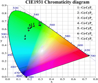
The EL spectra of the devices are shown in Fig. 6d. When ITO was biased positively, all the devices had stable cyan EL spectra (Fig. 6d), supporting the idea that the emission comes from the EML rather than the interface exciplex. The EL spectra of the devices had FWHM of ∼64 nm. Since the dopants efficiently trap the excitons produced in the host, no emission was seen from the CBP host or surrounding charge-transport layers. This suggests effective host-dopant energy transfer and charge containment. Fig. 6e shows that the EL spectra remained constant over a wide range of applied voltages, demonstrating excellent spectral stability. Table 4 lists the CIE 1931 standard chromaticity coordinates at 10 V (Fig. 7). These results provide evidence that the dyes are suitable for use in OLEDs.
Conclusion
We have synthesized seven new small-molecule-based organic compounds derived from carbazolyl cyanopyridone (Cz-CyP1-7) as possible cyan emitters, which can potentially be used in OLEDs. We confirmed their structures using spectroscopy tools and conducted comprehensive thermal, optical, electrochemical, electrical, theoretical, and EL studies. The results showed that these new bi-heterocyclic luminogens have good thermal stability and absorption and emission characteristics within the range of 374–39 and 489–510 nm, respectively, which leads to a band gap ranging from 2.36 to 2.74 eV. The DFT studies and energy level diagram analysis demonstrated that these fluorophores can facilitate charge transfer phenomena effectively. The electrochemical analysis showed that the luminophores have distinct oxidation and reduction behaviors, which confirms their potential bipolar carrier-transporting nature. We noticed that the substitution pattern of the cyanopyridone moiety distinctly influenced all the above-mentioned properties. Interestingly, these materials acted as cyan emitters in multilayer solution-processed OLEDs. Amongst them, the 4-hydroxyphenyl substituted fluorophore stood out with an impressive current efficiency of 13.16 cd A−1, power efficiency of 9.85 lm W−1, and external quantum yield of 5.41%. This study might undeniably open new avenues for D–A–D luminophore-based EL materials with efficient cyan-emitting OLEDs.Conflicts of interest
There are no conflicts to declare.Acknowledgements
The authors thank NITK, Surathkal, India, for providing laboratory facilities and computational resources. The authors are also indebted to the Chemistry Department, University of Mysore, India, for assisting with spectral facilities.References
- C. W. Tang and S. A. VanSlyke, Appl. Phys. Lett., 1987, 51, 913–915 CrossRef CAS.
- N. Chopra, J. S. Swensen, E. Polikarpov, L. Cosimbescu, F. So and A. B. Padmaperuma, Appl. Phys. Lett., 2010, 97, 033304 CrossRef.
- B. W. D’Andrade and S. R. Forrest, Adv. Mater., 2004, 16, 1585–1595 CrossRef.
- X. Qi, M. Slootsky and S. Forrest, Appl. Phys. Lett., 2008, 93, 193306 CrossRef.
- Y. Zhang, J. Song, J. Qu, P.-C. Qian and W.-Y. Wong, Sci. China: Chem., 2021, 64, 341–357 CrossRef CAS.
- Z. He, Y. Liu, Z. Yang, J. Li, J. Cui, D. Chen, Z. Fang, H. He, Z. Ye, H. Zhu, N. Wang, J. Wang and Y. Jin, ACS Photonics, 2019, 6, 587–594 CrossRef CAS.
- W. S. Jeon, T. J. Park, K. H. Kim, R. Pode, J. Jang and J. H. Kwon, Org. Electron., 2010, 11, 179–183 CrossRef CAS.
- Y. Nagai, H. Sasabe, J. Takahashi, N. Onuma, T. Ito, S. Ohisa and J. Kido, J. Mater. Chem. C, 2017, 5, 527–530 RSC.
- Q. Wu, R. Braveenth, H. Q. Zhang, I.-J. Bae, M. Kim and K. Y. Chai, Molecules, 2018, 23, 843 CrossRef PubMed.
- H. Gao, Z. Li, Z. Pang, Y. Qin, G. Liu, T. Gao, X. Dong, S. Shen, X. Xie, P. Wang, C.-S. Lee and Y. Wang, ACS Appl. Mater. Interfaces, 2023, 15, 5529–5537 CrossRef CAS PubMed.
- H. Lee, Y. I. Park, B. Kim, J.-H. Lee and J. Park, Opt. Mater. Exp., 2014, 4, 924–933 CrossRef.
- H. Ulla, B. Garudachari, M. N. Satyanarayan, G. Umesh and A. M. Isloor, Opt. Mater., 2014, 36, 704–711 CrossRef CAS.
- H. Ulla, M. Raveendra Kiran, B. Garudachari, M. N. Satyanarayan, G. Umesh and A. M. Isloor, Opt. Mater., 2014, 37, 311–321 CrossRef CAS.
- R. K. Gupta, H. Ulla, M. N. Satyanarayan and A. A. Sudhakar, Eur. J. Org. Chem., 2018, 1608–1613 CrossRef CAS.
- J. Jayabharathi, J. Anudeebhana, V. Thanikachalam, S. Sivaraj and A. Prabhakaran, RSC Adv., 2020, 10, 4002–4013 RSC.
- H. Shin, S. Lee, K.-H. Kim, C.-K. Moon, S.-J. Yoo, J.-H. Lee and J.-J. Kim, Adv. Mater., 2014, 26, 4730–4734 CrossRef CAS PubMed.
- P. L. Wu, X. J. Feng, H. L. Tam, M. S. Wong and K. W. Cheah, J. Am. Chem. Soc., 2009, 131, 886–887 CrossRef CAS PubMed.
- L. Xiao, S.-J. Su, Y. Agata, H. Lan and J. Kido, Adv. Mater., 2009, 21, 1271–1274 CrossRef CAS.
- Y. Sun, D. Zhong, S. Liu, L. Yue, Z. Feng, X. Deng, X. Chen, X. Yang and G. Zhou, J. Mater. Chem. C, 2023, 11, 4694–4702 RSC.
- D. Zhong, X. Yang, X. Deng, X. Chen, Y. Sun, P. Tao, Z. Li, J. Zhang, G. Zhou and W.-Y. Wong, Chem. Eng. J., 2023, 452, 139480 CrossRef CAS.
- J. Tagare, H. Ulla, M. N. Satyanarayan and S. Vaidyanathan, J. Lumin., 2018, 194, 600–609 CrossRef CAS.
- J. Tagare, H. Ulla, A. B. Kajjam, M. N. Satyanarayan and S. Vaidyanathan, ChemistrySelect, 2017, 2, 2611–2620 CrossRef CAS.
- F. Paquin, J. Rivnay, A. Salleo, N. Stingelin and C. Silva-Acuña, J. Mater. Chem. C, 2015, 3, 10715–10722 RSC.
- J. Tagare, H. Ulla, M. N. Satyanarayan and S. Vaidyanathan, J. Photochem. Photobiol. Chem., 2018, 353, 53–64 CrossRef CAS.
- S. Sohn, B. Hyun Koh, J. Y. Baek, H. Chan Byun, J. H. Lee, D.-S. Shin, H. Ahn, H.-K. Lee, J. Hwang, S. Jung and Y.-H. Kim, Dyes Pigm., 2017, 140, 14–21 CrossRef CAS.
- W. Zhu, M. Hu, R. Yao and H. Tian, J. Photochem. Photobiol. Chem., 2003, 154, 169–177 CrossRef CAS.
- S. Tongsuk, R. Malatong, T. Unjarern, C. Wongkaew, P. Surawatanawong, T. Sudyoadsuk, V. Promarak and N. Ruangsupapichat, J. Lumin., 2021, 238, 118287 CrossRef CAS.
- S. Chidirala, H. Ulla, A. Valaboju, M. R. Kiran, M. E. Mohanty, M. N. Satyanarayan, G. Umesh, K. Bhanuprakash and V. J. Rao, J. Org. Chem., 2016, 81, 603–614 CrossRef CAS PubMed.
- A. Baheti, C.-P. Lee, K. R. J. Thomas and K.-C. Ho, Phys. Chem. Chem. Phys., 2011, 13, 17210–17221 RSC.
- P. Ledwon, R. Motyka, K. Ivaniuk, A. Pidluzhna, N. Martyniuk, P. Stakhira, G. Baryshnikov, B. F. Minaev and H. Ågren, Dyes Pigm., 2020, 173, 108008 CrossRef CAS.
- K. R. Justin Thomas, J. T. Lin, M. Velusamy, Y.-T. Tao and C.-H. Chuen, Adv. Funct. Mater., 2004, 14, 83–90 CrossRef.
- S. Kang, J.-S. Huh, J.-J. Kim and J. Park, J. Mater. Chem. C, 2020, 8, 11168–11176 RSC.
- N. Pilicode, N. K. M. M. Acharya, P. Naik, S. M. N and A. V. Adhikari, J. Photochem. Photobiol. Chem., 2019, 378, 38–45 CrossRef CAS.
- D. R. Vinayakumara, H. Ulla, S. Kumar, M. N. Satyanarayan and A. Vasudeva Adhikari, Mater. Chem. Front., 2018, 2, 2297–2306 RSC.
- D. R. Vinayakumara, R. Kesavan, S. Kumar and A. V. Adhikari, Photochem. Photobiol. Sci., 2019, 18, 2052–2060 CrossRef CAS PubMed.
- D. R. Vinayakumara, H. Ulla, S. Kumar, A. Pandith, M. N. Satyanarayan, D. S. Shankar Rao, S. Krishna Prasad and A. Vasudeva Adhikari, J. Mater. Chem. C, 2018, 6, 7385–7399 RSC.
- H. Ulla, M. R. Kiran, S. N. Ansari, M. W. Alam, W. M. Girma and G. Gedda, Opt. Mater., 2024, 147, 114602 CrossRef CAS.
- V. K. S. H. Ulla, R. K. M. B. R. Bhat and A. V. Adhikari, Dyes Pigm., 2023, 219, 111560 CrossRef.
- K. S. Vishrutha, H. Ulla, M. Raveendra Kiran, B. Ramachandra Bhat and A. Vasudeva Adhikari, J. Photochem. Photobiol. Chem., 2023, 435, 114344 CrossRef CAS.
- G. Umasankar, H. Ulla, C. Madhu, G. R. Reddy, B. Shanigaram, J. B. Nanubolu, B. Kotamarthi, G. V. Karunakar, M. N. Satyanarayan and V. J. Rao, J. Mol. Struct., 2021, 1236, 130306 CrossRef CAS.
- P. K. Pandey, H. Ulla, M. N. Satyanarayan, K. Rawat, A. Gaur, S. Gawali, P. A. Hassan and H. B. Bohidar, ACS Appl. Nano Mater., 2020, 3, 1289–1297 CrossRef CAS.
- H. Ulla, M. R. Kiran, B. Garudachari, T. N. Ahipa, K. Tarafder, A. V. Adhikari, G. Umesh and M. N. Satyanarayan, J. Mol. Struct., 2017, 1143, 344–354 CrossRef CAS.
Footnote |
| † Electronic supplementary information (ESI) available. See DOI: https://doi.org/10.1039/d3ma00922j |
| This journal is © The Royal Society of Chemistry 2024 |

