
 Open Access Article
 This Open Access Article is licensed under a Creative Commons Attribution-Non Commercial 3.0 Unported Licence
Single transition atom-doped antimonene as a highly efficient electrocatalyst for the nitrogen reduction reaction: a DFT study†
Xiaopeng
Shen
 *a,
Chao
Liu
b and
Qinfang
Zhang
*c
*a,
Chao
Liu
b and
Qinfang
Zhang
*c
aDepartment of Chemistry and Chemical Engineering, Yancheng Institute of Technology, Yancheng, Jiangsu 224051, P. R. China. E-mail: shenxpeng@ycit.edu.cn
bSchool of Materials Science and Engineering, Yancheng Institute of Technology, Yancheng 224051, P. R. China
cKey Laboratory for Ecological-Environment Materials of Jiangsu Province, Yancheng Institute of Technology, Yancheng 224051, P. R. China. E-mail: qfangzhang@gmail.com
First published on 6th December 2023
Abstract
The synthesis of ammonia (NH3) through the electrocatalytic nitrogen reduction reaction (NRR) at ambient temperature and pressure provides a green low-carbon synthetic route for ammonia production. The rational design and optimization of low-cost and high-efficiency NRR electrocatalysts is a fascinating and challenging topic in chemistry. In this study, using first-principles calculations based on density functional theory (DFT), the electrocatalytic performance for the NRR of a series of single transition metal (TM) atoms doped on defective antimonene monolayer (SbML) was systematically explored. It was found that Mo@SbML exhibits the best catalytic activity for the NRR with a limiting potential of −0.34 V along the enzymatic pathway, which is due to the interaction between the empty d-orbitals of the TM and the lone pair electrons of N2 molecules. Meanwhile, our computational results show that Mo@SbML also has high selectivity and stability. In addition, to further investigate the origin of effective NRR activities, the Bader charge, the electronic properties, the crystal orbital Hamilton population (COHP), the charge difference density (CDD) and the partial density of states (PDOS) were discussed and analyzed concretely. This work not only shows that SbML could be a promising anchor material for the NRR, but also provides useful clues for the development of novel electrocatalysts with high activity and stability.
1. Introduction
Ammonia (NH3) is not only an important nutrient for plant growth in nature, but also a pivotal manufactured inorganic chemical which has been extensively applied in various fields, such as fertilizers, medicines, dyes and energy-rich materials.1–3 Nowadays, the large-scale synthesis of NH3 is still mainly based on the traditional Haber–Bosch (H–B) process, which requires reaction conditions at high temperatures (400–500 °C) and high pressures (150–300 atm) to break the inert N![[triple bond, length as m-dash]](https://www.rsc.org/images/entities/char_e002.gif) N triple bond.4,5 The industrial H–B process consumes a lot of energy and produces a large amount of carbon emissions, causing a serious environmental problem. Therefore, it is extremely important to develop a new substitution approach to achieve environmentally friendly and cost-effective N2 reduction for NH3 synthesis under room temperature conditions.
N triple bond.4,5 The industrial H–B process consumes a lot of energy and produces a large amount of carbon emissions, causing a serious environmental problem. Therefore, it is extremely important to develop a new substitution approach to achieve environmentally friendly and cost-effective N2 reduction for NH3 synthesis under room temperature conditions.
Recently, the electrocatalytic N2 reduction to NH3 under ambient conditions, inspired by biological nitrogen (N2) fixation, has become a leading area in the field of electrochemistry.6,7 Undoubtedly, electrocatalysts play a crucial role in the NRR process. Nevertheless, the low economic efficiency, unsatisfactory activity and selectivity, and low Faraday yield of the reported NRR electrocatalysts enormously restrict their practical industrial applications. Interestingly, new single atom catalysts (SACs) have attracted a great deal of research interest due to their outstanding catalytic activity, high reaction selectivity, maximum atom utilization, tunable coordination structures and electronic properties.8–10 Over the past decade, the catalytic performance of SACs for the CO2 reduction reaction (CO2RR),11,12 oxygen evolution reaction (OER),13,14 oxygen reduction reaction (ORR),15–23 hydrogen evolution reaction (HER)24,25 and NRR26–50 has been extensively studied and reported.
Notably, with the development of theoretical computational chemistry, theoretical calculation of the electrocatalytic NRR has attracted much attention, which proposed several high-activity catalysts and possible reaction processes. For example, by means of DFT, a wide range of TM atoms have been anchored on various 2D nanomaterials, including graphene and nitrogen doped derivatives,51–54 defective Fe3GeTe2 monolayers,55,56 MBene monolayers,57 transition metal borides,58,59 graphdiyne (GDY),45,60 MoS2,32 boron nitride (BN)35 and ZnO monolayers,61 which can be considered as highly efficient electrocatalysts for the NRR. Therefore, heteroatom doping to adjust the interaction between supports and heteroatoms can improve the catalytic activity of SACs for the NRR. However, during experiments, the single metal atoms of SACs can easily migrate and polymerize into metal nanoclusters due to high surface energy, ultimately leading to the deactivation of SACs. Herein, searching for appropriate support materials to achieve steady and high efficiency SACs towards the NRR is an urgent issue.
Antimonene (Sb), as a novel 2D semiconducting monolayer of group-VA elements, was first predicted and identified by Zhang's group in 2015.62 Subsequent studies further revealed that the Sb monolayer possesses desirable stability, high electrical conductivity63 and thermal conductivity,64 high carrier mobility and fascinating electronic properties,65 and has great potential applications in the field of electrocatalyst materials. Moreover, Gusmão et al. evaluated the electrochemical performance of As, Sb, and Bi exfoliated nanosheets in the HER, OER and ORR.66 The results have shown Sb to be a wide-pH-range catalyst for the HER. Zhang et al. reported that few-layer black phosphorus (BP) nanosheets can be used as an efficient nonmetallic catalyst for the electrocatalytic NRR.67 Then, Lin et al. designed TM-SACs supported on BP for the electrocatalytic nitrogen reduction.68 The results showed that there is a volcanic relationship between the number of electrons transferred from the metal center to the P ligand and the NRR activity. However, BP exhibits poor stability when exposed to oxygen and water environments. This fatal disadvantage severely limits its industrial applications.
Moreover, Xu et al. designed a competitive NRR electrocatalyst with an ultralow overpotential (0.10 V) via the enzymatic pathway of the V doped arsenene nanosheet.40 In particular, experimental researchers have successfully fabricated oxidized Sb nanosheets69 and Au nanoparticles anchored on Bi nanosheets, and demonstrated their excellent performance for the NRR under ambient conditions.70 Cao et al. also fabricated few-layer antimonene with edge defects through chemical exfoliation using H2SO4 for the first time. The obtained antimonene shows better NRR performance than bulk Sb, which contributes to the high density of active edge sites.71 As far as we know, there are only a few reports of theoretical or experimental studies on 2D Sb monolayers as an NRR catalyst.
In this study, we theoretically propose a new class of SACs consisting of 3d, 4d and 5d TMs doped on a defective SbML with Sb monovacancy (SbML), named TM@SbML, and systematically investigate the electrochemical NRR mechanism to produce NH3 using DFT calculations. We hope that this work will expand new and interesting 2D material-supported SACs for efficient NRR.
2. Computational methods
All spin-polarized DFT calculations were implemented with the projector-augmented wave (PAW) method72 and the Perdew–Burke–Ernzerhof (PBE) exchange–correlation functional73 using the Vienna Ab Initio Simulation Package (VASP).72,74 For geometry optimization, the plane-wave cut-off energy was set as 450 eV. The convergence criteria for energy and force were set as 10−5 eV per atom and 0.02 eV Å−1, respectively. The SbML supercell was modeled as 5 × 5 × 1 with a vacuum distance of 20 Å along the z-direction to prevent the interaction between two nearby periodic repeating cell. The reciprocal space was sampled by 5 × 5 × 1 and 21 × 21 × 1 for geometry optimization and electronic structure calculations, respectively. Meanwhile, the van der Waals (vdW) interaction between the TM-doped SbML and reaction intermediate was considered by the DFT-D3 method.75The binding energy (Eb) can be calculated using the equation:
| Eb = ETM@SbML − ESbML − ETM | (1) |
The adsorption energy (Eads) of reaction intermediates on the TM@SbML catalysts can be calculated as follows:
| Eads = Etotal − ETM@SbML − Eadsorbate | (2) |
The changes in Gibbs free energy (ΔG) of each hydrogenation step in the NRR process were calculated by using the computational hydrogen electrode (CHE) model developed by Nørskov and co-workers.76,77 ΔG could be determined as follows:
| ΔG = ΔE + ΔEZPE − TΔS + ΔGU + ΔGpH | (3) |
![[thin space (1/6-em)]](https://www.rsc.org/images/entities/char_2009.gif) 10 × kBT × pH, where kB is the Boltzmann constant under standard reaction conditions (pH = 0, 298.15 K, and 101325 Pa).78,79 The entropies of the gas molecules (i.e., H2, N2, and NH3) were taken from the NIST database.80
10 × kBT × pH, where kB is the Boltzmann constant under standard reaction conditions (pH = 0, 298.15 K, and 101325 Pa).78,79 The entropies of the gas molecules (i.e., H2, N2, and NH3) were taken from the NIST database.80
The limiting potential (UL) is defined as UL = −ΔGmax/e, where ΔGmax is the maximum positive value of ΔG. The UL was the smallest applied negative potential to keep every elemental step spontaneous. Therefore, it was utilized to assess the intrinsic NRR activity of catalysts. The dynamic barrier of adsorbed intermediates during the entire NRR process was calculated using the climbing-image nudged elastic band (CI-NEB) method.81Ab initio molecular dynamics (AIMD) simulations were performed to evaluate the thermodynamic stability of the catalyst. Considering that Sb is a relatively heavy element with d orbitals, the electron localization of strong d electrons and the relativistic effects including the spin–orbit coupling inside the SbML cannot be ignored. As reported in previous literature,35,36 the DFT+U method cannot correct the N2 molecule, and the U values have little influence on the whole system. Given the computational time and cost, we adopted the DFT/PAW method in this work.
3. Results and discussion
3.1. Screening of TM@SbML as the NRR electrocatalyst
Initially, considering that the exposed Sb atoms on the pristine SbML surface may act as active sites for N2 activation, we investigated the catalytic performance of the pristine SbML in the NRR process. As shown in Fig. S1 (ESI†), the N2 molecule has been adsorbed on the pristine SbML with end-on and side-on configurations. The corresponding adsorption energies, N–N bond lengths and the distance from the Sb atom of the SbML surface to the nearest N atom are summarized in Table S1 (ESI†); the large positive adsorption energies (4.19 eV and 4.21 eV) and large N–S distances (3.71 Å and 3.91 Å) indicate the weak interactions between the N2 and Sb atoms. This means that the pristine SbML is not an appropriate NRR electrocatalyst due to their poor performance for inert NN triple bond activation. Therefore, single TM atoms doped onto the defective SbML will be focused on in the following research.
Then, we constructed a defective SbML with Sb monovacancy to anchor single 3d, 4d and 5d TM atoms (Fig. 1(a)). After full optimization without any constraints, the binding energies of these 29 different SAC models are calculated as shown in Fig. 1(b)–(d). The results show that the binding energies of Y@SbML, Cd@SbML and Hg@SbML are all lower than −2.00 eV, suggesting that these SAC models are not suitable NRR catalysts due to weak interactions between the dopant atoms and the substrate. Among the 29 different SAC structures, most SACs possess quite negative binding energies larger than −4.50 eV, which means that TM atoms can be immobilized stably on the defective SbML. It is worth mentioning that the bond lengths of TM-Sb range from 2.46 to 2.79 Å; they are all shorter than the Sb–Sb bond length (2.89 Å) in the pristine SbML. This is consistent with the larger calculated binding energies of TM@SbML systems.
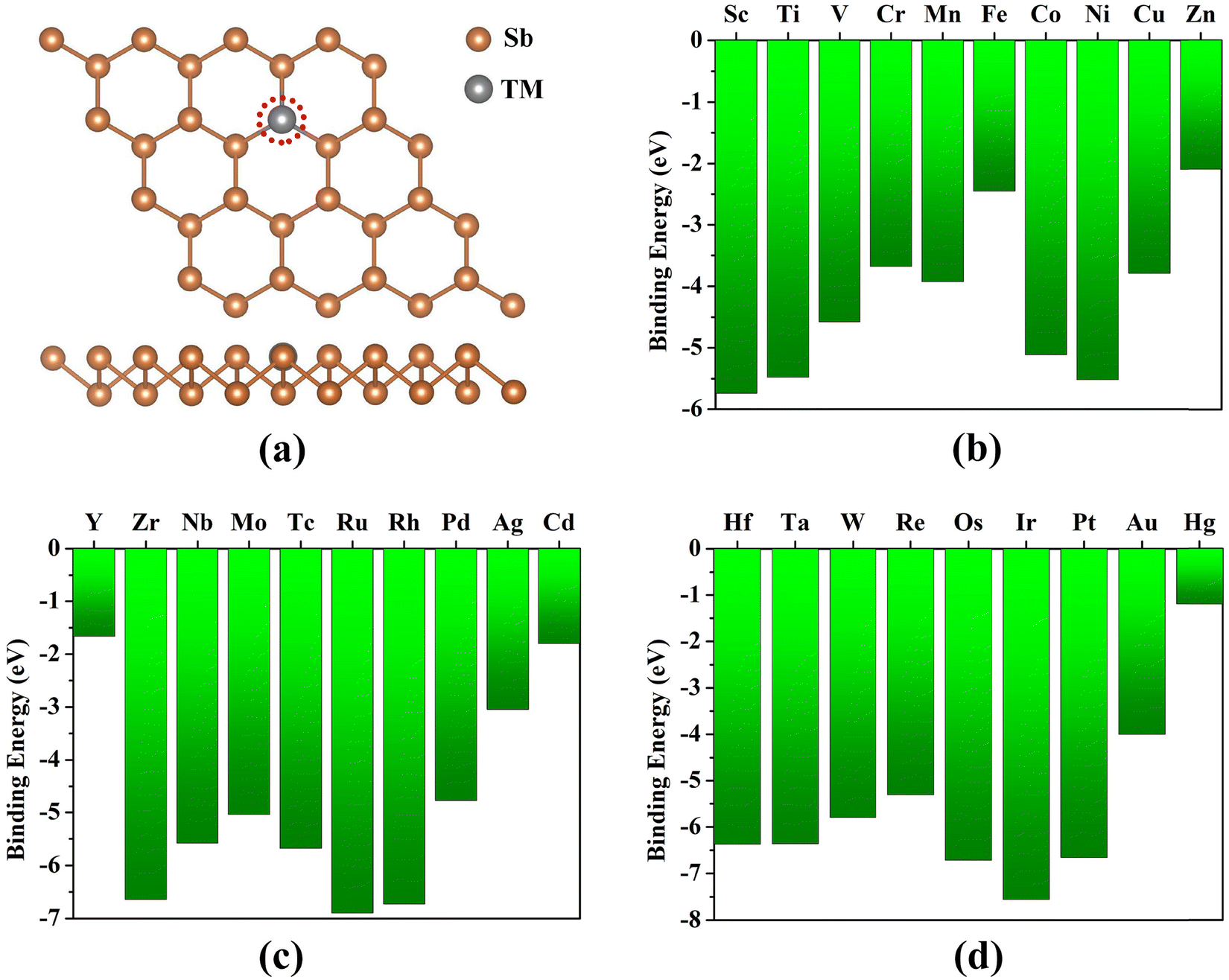 | ||
| Fig. 1 (a) The top and side views of the SbML with Sb monovacancy. The doped sites of TM are encircled in red colors. The binding energies of (b) 3d, (c) 4d and (d) 5d TM atoms doped in the SbML, respectively. | ||
According to previous investigations,82–84 the entire NRR process is composed of six complicated hydrogenation reaction steps, that is N2 + 6H+ + 6e− → 2NH3, which both begin with end-on and side-on adsorption configurations of N2 molecules (Fig. S2a, ESI†). After the structure optimization, for N2 adsorption on Y@SbML, Zn@SbML, Ag@SbML, Cd@SbML, Au@SbML and Hg@SbML with end-on and side-on configurations, we found obvious structural deformations in both configurations. This suggested that these six SAC models cannot be the electrocatalysts for the NRR. Particularly, the side-on adsorption configuration of Co@SbML, Ni@SbML, Cu@SbML, Ru@SbML, Rh@SbML, Pd@SbML, Ir@SbML and Pt@SbML would change to the end-on configuration, indicating these side-on configurations are not stable. The end-on and side-on N2 molecule adsorption configurations and corresponding Eads are presented in Fig. S2b–d (ESI†). It was found that all calculated Eads values were negative (from −0.07 eV to −1.67 eV) when adsorption occurred in the end-on and side-on configurations except for Cr@SbML, for which the Eads value for N2 adsorption in the end-on configuration was positive (0.38 eV), indicating that N2 did not adsorb on Cr@SbML via the end-on configuration. Based on the Sabatier principle,85 the Eads value should be moderate between −0.5 and −1.0 eV. Too negative Eads value means N2 molecules were adsorbed too strong, and then the activity of TM@SbML catalysts would be inhibited. However, due to weak adsorption, the active TM atoms can easily aggregate, resulting in a rapid decline in catalytic activity and catalyst deactivation. To further explore the TM–N2 interaction for N2 adsorbed on TM@SbML, the Bader charge transfer of different TM@SbML with N2 end-on and side-on adsorption configures is determined and is displayed in Fig. S3 (ESI†). Obviously, significant charge transfer (0.12–2.15 e−) occurred from TM atoms to the N2 molecule except for 3d TM atoms of Co (0.08 e−), Ni (0.01 e−), and Cu (0.08 e−). One can see that the early TM@SbML in the same period shows a larger charge transfer from TM atoms to N2 molecules. This can be explained by the fact that it is more easy for early TM atoms to lose electrons than the later TM atoms in the same period. The interaction leads to a more negative Eads value, suggesting a stronger binding strength with N2, thereby weakening the NN bond, which contributes to the progress of the NRR process.
Previous studies have proved that the free energy change of the first protonation (ΔG(*N2–*NNH)) or last protonation steps (ΔG(*NH2–*NH3)) had the maximum ΔG values among the different NRR pathways.32,35,57 In order to search for the optimal NRR catalysts from TM@SbML systems efficiently, we used the first standard criteria: ΔGmax ≤ 0.49 eV84 to screen out the most suitable candidate as an electrocatalyst for the NRR. The calculated ΔG(*N2–*NNH) and ΔG(*NH2–*NH3) values for TM@SbML systems studied are presented in Fig. 2(a). The results show that only the ΔG(*N2–*NNH) (with end-on and side-on configurations) and ΔG(*NH2–*NH3) values of the Mo@SbML catalyst are lower than 0.49 eV simultaneously. Secondly, considering that the HER was a major competing reaction,86–88 which greatly affected catalyst selectivity towards the NRR. This is because the adsorbed H* species could occupy the active metal sites of SACs, thereby blocking the NRR process and thus significantly affecting its faradaic efficiency (FE).89 In order to select the good reaction selectivity SACs for the NRR, we computed the ΔG(*N2) values for the NRR versus the ΔG(*H) values for the HER for the above screened out seven catalyst candidates (Fig. 2(b)). The more lower the ΔG values, the more favorable the reactions to occur. Fig. 2(b) shows that the ΔG(*N2) values for the adsorption with the end-on configuration were lower than that for the adsorption with the side-on configuration. Only Cr@SbML SAC exhibits positive values of ΔG(*N2) and ΔG(*H), which means poor chemical adsorption. Furthermore, the ΔG(*N2) values of Ti@SbML, V@SbML, Nb@SbML, Mo@SbML and Tc@SbML systems were lower than their ΔG(*H) values, implying that these SACs possess high selectivity towards the NRR. Conversely, the Os@SbML catalyst strongly favored H adsorption for the HER rather than N2 adsorption for the NRR, due to its ΔG(*H) values being lower than the ΔG(*N2). Finally, we would choose Mo@SbML for further exploration. In view of its ΔG(*N2–*NNH) (with both end-on and side-on configurations) and ΔG(*NH2–*NH3) values all less than 0.49 eV, and with smaller ΔG(*N2) for the NRR compared to ΔG(*H) for the HER, Mo@SbML could exhibit excellent catalytic activity for the NRR with a small limiting potential (UL) and a higher yield of NH3 production.
 | ||
| Fig. 2 (a) Screening results of TM@SbML for the NRR based on the free energy changes of the first hydrogenation step (ΔG(*N2–*NNH)) with end-on or side-on configurations and last hydrogenation steps (ΔG(*NH2–*NH3)), respectively. The TM@SbML systems meet the criteria marked with the red circle. (b) The ΔG(*H) values of the HER and ΔG(*N2) values of the NRR on TM@SbML (TM = Ti, V, Cr, Tc, Mo, Nb and Os), where the yellow region represents the NRR dominant region. | ||
3.2. NRR mechanisms on Mo@SbML
As described in recently reported studies,90–94 there are four typical possible NRR mechanisms, consisting of distal, alternating, consecutive and enzymatic reaction pathways. The distal and alternating pathways begin in the end-on configurations, while the consecutive and enzymatic pathways begin in the side-on configurations. Specifically, in the distal pathway, the first three proton–electron pairs (H+/e−) attack the distal N atoms continuously to form the first NH3 molecule. Then the remaining N atom is added by other three H+/e− to generate the second NH3 molecule. While in the alternating pathway, six H+/e− pairs were reacted alternately onto two different N atoms. For the enzymatic pathway of the side-on adsorption model, both two N atoms of the N2 molecule were chemically bonded to a single TM atom, and then the H+/e− pairs attack the two N atoms alternately until the formation of the NH3 molecules. Along the consecutive pathway, the H+/e− pairs continuously attack the one N atom to produce one NH3 and then attack the residual N atom to release the second NH3. The optimized structures of each elementary reaction step intermediates of the four NRR reaction pathways are presented in Fig. 3 and 4. The Gibbs free energy diagrams of NRR processes on Mo@SbML are depicted in Fig. 5.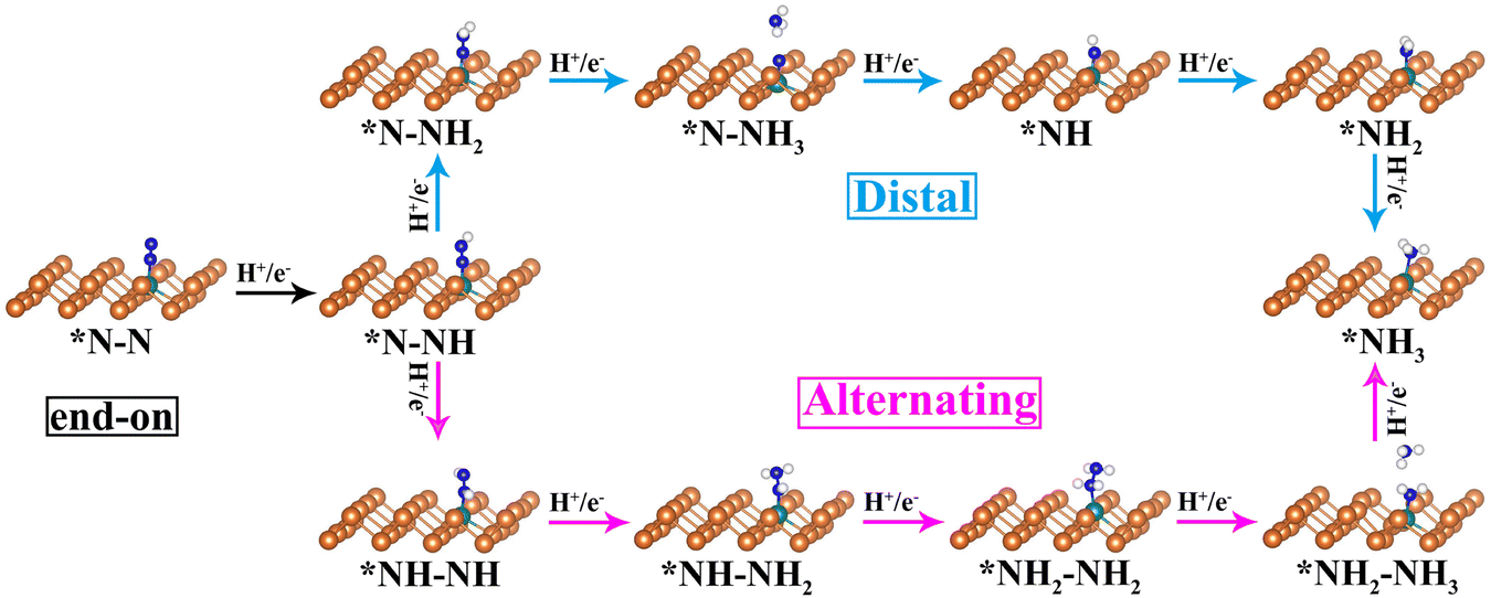 | ||
| Fig. 3 The optimized geometry structures of key intermediates for the NRR on the Mo@SbML with the N2 end-on adsorption configuration. | ||
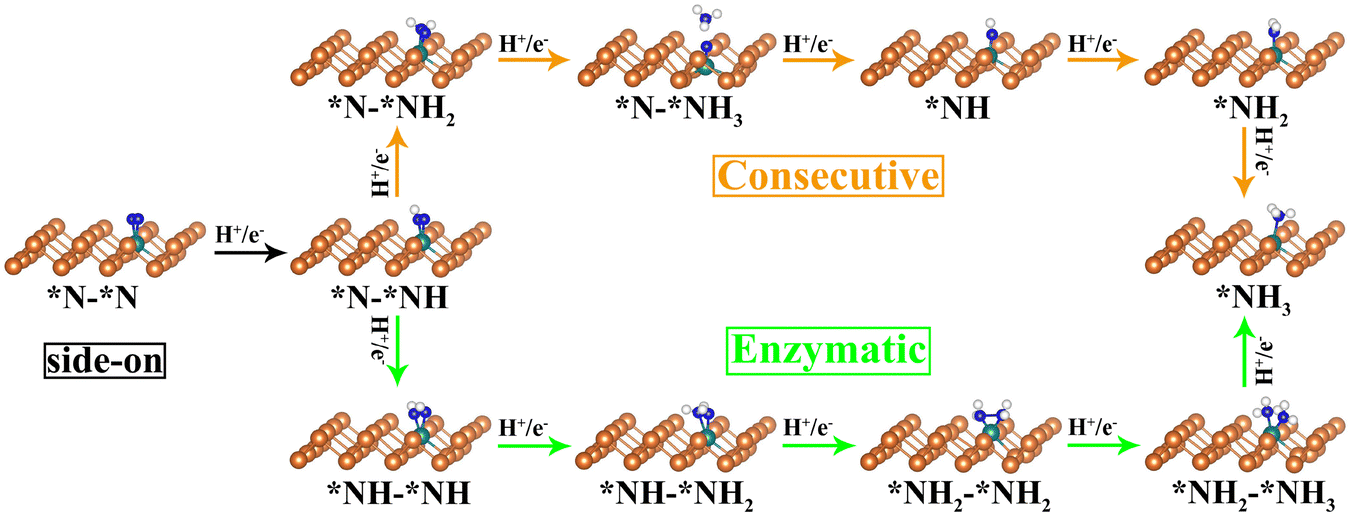 | ||
| Fig. 4 The optimized geometry structures of key intermediates for the NRR on the Mo@SbML with the N2 side-on adsorption configuration. | ||
 | ||
| Fig. 5 Gibbs free energy diagrams of NRR processes at zero (blue lines) and applied potential (red lines) via the (a) distal, (b) alternating, (c) consecutive and (d) enzymatic pathways on Mo@SbML, respectively. | ||
As shown in Fig. 5(a) and (b), the end-on adsorption of N2 molecules on Mo@SbML is a spontaneous (exothermic) process with a negative ΔG value (−0.27 eV), indicating the strong binding between N2 and Mo@SbML. Meanwhile, the NN bonds are activated during the adsorption, as the bond length stretches from 1.12 Å to 1.15 Å. Subsequently, the formation of *N–NH is the same in the distal (Fig. 5(a)) and alternating (Fig. 5(b)) pathways, and the free energy is calculated to increase by 0.34 eV, suggesting that the first step is a non-spontaneous (endothermic) process. For the subsequent second and third reaction steps of the distal pathway, the free energy decreases by 0.21 eV and 0.60 eV. This indicated that the second and third reaction steps were an exothermic process that could occur spontaneously. Then, with the generation of *N–NH3, the first NH3 molecule is released from the catalyst surface. After that, the H+/e− pairs one after the other were added onto another N atom to produce the second NH3. The corresponding ΔG values for the fourth, the fifth and the sixth reaction steps were −0.47 eV, −0.40 eV and 0.36 eV, respectively. These results revealed that the first and the last hydrogenation reaction is an endothermic step with positive ΔG values of 0.34 eV and 0.36 eV. Therefore, the last hydrogenation reaction can be viewed as the potential determining step (PDS) of the distal pathway of the NRR on Mo@SbML. Along the alternating pathway, the PDS is the fourth hydrogenation reaction with ΔG = 0.58 eV.
Regarding the consecutive and enzymatic pathways on (Fig. 5(c) and (d)) Mo@SbML, the PDSs are the last protonation step (*NH2 → *NH3) and the first protonation step (*N–*N → *N–*NH) with the UL of −0.36 and −0.34 V, respectively. In addition, the Poissson–Boltmann implicit solvation model95 was employed to consider the solvent effects, and the dielectric constant (ε) of water is set as 80. The calculated Gibbs free energy diagrams of the NRR with solvation for Mo@SbML along the enzymatic pathway are shown in Fig. S4 (ESI†). The limiting potential values (UL) with and without solvation effects are listed and compared in Table S2 (ESI†). The results indicate that after considering the effect of solvation, there is a limited impact on the potential determining step (PDS) and UL. From this respect, the solvation correction was abandoned throughout the computations. From these calculated results, we can conclude that the NRR process on Mo@SbML prefers to occur through the enzymatic pathway with a quite lower UL value of −0.34 V. To the best of our knowledge, the NRR UL of −0.34 V is less negative compared to that of recently reported Re@MoS2 (−0.43 V),32 Mn@GY (−0.36 V),36 Cr@GY (−0.52 V),44 BN-Cr-graphdiyne (−0.63 V)49 and B-doped defective ReS2 (−0.53 V).50 Hence, the Mo@SbML SAC is a high-performance electrocatalyst for the NRR.
3.3. Origin of the excellent catalytic activity of Mo@SbML
To better understand the excellent catalytic activity of Mo@SbML from the perspective of charge transfer, we further calculate the Bader charge variation in elementary hydrogenation steps through the enzymatic pathway. According to previous literature,32,35 the Mo@SbML system could be divided into three moieties: the SbML substrate with the exception of three Mo-nearby Sb atoms (moiety 1), Mo and its three neighboring Sb atoms (moiety 2), and the adsorbed NxHy species (moiety 3). Bader charge analysis shows that there are obvious charge fluctuations among the three moieties (Fig. 6(a)). Specifically, after the adsorption of N2 molecules with a side-on configuration, the chemical bond is formed between the N2 molecule with the Mo atom. The N2 molecule (moiety 3) gains 0.51 e− from the Mo@SbML as the electronegativity of N (3.04) was larger than that of Mo (1.16), and the SbML substrate (moiety 1) and Mo and its three neighboring Sb atoms (moiety 2) lost 0.22 e− and 0.29 e−, respectively. | ||
| Fig. 6 (a) Bader charge for three Mo@SbML moieties along the enzymatic pathway. (b) The N–N bond lengths through the enzymatic pathway. | ||
The corresponding electron transfers can also be reflected in the charge density difference (CDD) shown in Fig. S5 (ESI†). Apparently, the charge accumulation shown in yellow colour mainly occurs around the Mo–N bonds, while the charge depletion shown in cyan colour occurs surroundings the N–N bond and Mo atoms. The charge aggregation and depletion can occur at the same time in the absorbed N2 and the Mo@SbML. This indicates that the two N atoms gain electrons and lose electrons simultaneously. Thus highly consistent with the concept of the “acceptance–donation” process between the TM d orbitals and N2 frontier molecular orbitals,96,97 the empty d orbitals of Mo atoms can accept the lone-pair electrons of N2, while the occupied d orbitals of Mo atom can provide electrons to the antibonding orbitals of N2. So while the N2 adsorbed on the surface of Mo@SbML via side-on configuration, the NN triple bond can be activated more efficiently and make the subsequent hydrogenation steps more smoothly. This is in good accordance with the obvious elongation of bonds length of N2 (Fig. 6(b)).
Moreover, the NxHy species (moiety 3) always obtained the electrons from the other moieties, except for the last *NH3 species (Fig. 6(a)). In short, the SbML (moiety 1) can be considered as an electron donor, and the Mo and three neighboring Sb atoms (moiety 2) act as an electron transfer medium for the SbML (moiety 1) and the NxHy species (moiety 3). Furthermore, Fig. 6(b) displays the N–N bond lengths (dN–N) of NxHy species for each step via the favorable enzymatic pathway. We found a sharp increase of the dN–N value (from 1.20 Å to 2.67 Å) until the second NH3 molecule has emerged, which indicates the triple bond of N2 undergoing activation elongation until breaking.
We subsequently analyzed the changes in the electronic structure over the NRR process. The changes in the partial density of states (PDOS) projected on the N-s, N-p, Sb-s, Sb-p, Sb-d and Mo-d orbitals near the Fermi levels before and after the N2 adsorption on Mo@SbML via the side-on configuration are presented in Fig. 7. By comparing the PDOS of N-s and N-p in Fig. 7(a) and (d), the orbitals of adsorbed N2 moved away from the Fermi level toward deep energy levels. This would lead to the donation of electrons by N2 molecules to Mo@SbML. Particularly, after N2 was adsorbed on the defective SbML with the side-on configuration, strong hybridization occurred between the N-p, Sb-p and Mo-d orbitals below the Fermi level (from −3.48 to −0.17 eV) and above the Fermi level (from 0.42 to 0.76 eV) (Fig. 7(d)). This indicates that there is a remarkable splitting and hybridization for the antibonding orbitals of the N2 molecule. This hybridization of the orbitals certainly induces charge transfer between Mo@SbML and N2, which is crucial for the activation of N2 and the elongation of the NN bond, thus favoring the electrochemical NRR process. Furthermore, the band structures of the pristine SbML, the defective SbML with Sb monovacancy, Mo@SbML and N2 adsorption on Mo@SbML with the side-on configuration are plotted in Fig. S6 (ESI†). The pristine SbML is a semiconductor with a band gap of 1.29 eV (Fig. S6a, ESI†) which is close to the reported literature.98 While removing one Sb atom to form the monovacancy SbML, the original semiconducting behavior became metallic, due to the crossing of the original bottom conduction bands (BCB) over the Fermi-level (Fig. S6b, ESI†). Interestingly, semiconducting behavior with a small band gap (0.89 eV) can also be observed in the Mo@SbML system (Fig. S6c, ESI†). After adsorbing N2 molecules on the defective SbML with the side-on configuration, the band gap is then decreased to 0.49 eV (Fig. S6d, ESI†). This is mainly due to the new chemical bonds formed between the N2 molecule and the Mo@SbML.
 | ||
| Fig. 7 The partial density of states (PDOS) of (a) gaseous N2-s and N2-p, (b) defective SbML Sb-s, Sb-p and Sb-d, (c) Sb-s, Sb-p, Sb-d and Mo-d before N2 adsorbed on the defective SbML, and (d) after N2 adsorbed on the defective SbML with the side-on configuration. The Fermi-level is set to be zero denoted by black dash line. | ||
It is widely known that a smaller band gap leads to higher conductivity, which could potentially enhance the catalytic performance of the electrochemical NRR. According to the equation: the electrical conductivity σ ∝ exp(−Eg/2kBT), where Eg is the electronic band gap, kB is the Boltzmann's constant, and T is the temperature.99 As compared to Mo@SbML at room temperature (T = 298.15 K), the electrical conductivity of the side-on N2 adsorption on Mo@SbML is approximately 2400 times greater. This excellent conductivity makes it easier to achieve the electrocatalytic NRR in experiments. In addition, we have also calculated the integrated-crystal orbital Hamilton population (ICOHP) to quantitatively measure the activation degree of N2.100,101 Normally, the less negative the ICOHP-value, the more active the N2 molecule.101,102Fig. 8 depicts that there is an obvious rise for the ICOHP-value from −23.52 eV (free N2) to −10.28 eV (absorbed N2 with the end-on configuration) and −8.89 eV (absorbed N2 with the side-on configuration), indicating the more activated N–N bond in the side-on configuration than in the end-on configuration. This is consistent with the less negative UL value along the enzymatic pathway compared to those along distal and alternating pathways. As shown in Table S3 (ESI†), we compared the integrated COHP (ICOHP) values (eV) and the corresponding limiting potential (UL) (eV) from previous literature. It is not hard to find that the less negative the ICOHP and UL values, the higher the catalytic activity. This may provide a useful method to tune and optimize potential NRR electrocatalysts.
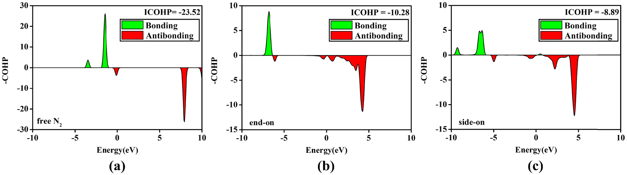 | ||
| Fig. 8 The crystal orbital Hamilton population (COHP) between N–N of (a) free N2 molecule; N2 adsorbed on Mo@SbML with (b) end-on configuration and (c) side-on configuration. | ||
Furthermore, we have calculated the entire reaction free energies and transition states of Mo@SbML along the enzymatic pathway to gain a full understanding of electrocatalytic NRR activity. The corresponding calculation results are plotted in Fig. S7 (ESI†). The largest reaction energy barrier in the entire NRR process is 0.84 eV (TS5) for the first NH3 molecule formation, which means the NH3 desorption from the catalyst surface is the dynamic rate-determining step. To verify the thermal stability of Mo@SbML, we employed the ab initio molecular dynamics (AIMD) simulation at 500 K for 5 ps with a time step of 1 fs using a Nosé–Hoover thermostat. As shown in Fig. S8 (ESI†), a narrow fluctuation of the energy and temperature was observed, and no significant structural deformations emerged even at a high temperature of 500 K, convincingly demonstrating the high thermodynamic stability of Mo@SbML.
4. Conclusions
In brief, we conducted a systematic study on a series of transition metal atoms supported on the defective SbML as potential NRR electrocatalysts, using DFT calculations. Our calculation results indicated that Mo@SbML presents outstanding electrocatalytic activity for the NRR process, particularly with a very low limiting potential of −0.34 V via the enzymatic pathway, along with high selectivity and high thermodynamic stability. Combined with the analysis of electronic properties and Bader charge, the acceptance-donation process between the TM and N2 which effectively activated the NN triple bond has been clearly illustrated. The COHP results reflect that the binding strength of the N–N bond decreased dramatically after the adsorption of N2 on Mo@SbML. Moreover, during the NRR process, the SbML can act as an electron container, and Mo-3Sb atoms species plays a role in transmitting the charge between the NxHy species and the SbML. We hope that this work can provide more valuable guidance for the theoretical and experimental studies of SACs based on 2D materials for NRR chemistry.
Author contributions
C. Liu and Q. F. Zhang conceived the research and were responsible for the selection of the methodology and software. X. P. Shen conducted the theoretical calculation and analyzed the conclusion. C. Liu and Q. F. Zhang were responsible for data curation. X. P. Shen and Q. F. Zhang drafted the paper. All authors contributed equally to writing, reviewing and editing the manuscript.Conflicts of interest
The authors declared that they have no conflicts of interest in this work.Acknowledgements
This work was supported by the National Natural Science Foundation of China (no. 51902282 and 12274361), the Qinglan Project of Jiangsu of China, Natural Science Foundation of Jiangsu Province (BK20211361), the College Natural Science Research Project of Jiangsu Province (20KJA430004) and Funding for school-level research projects of Yancheng Institute of Technology(xjr2020043). We acknowledge the Beiiing PARATERA Tech Co., Ltd (https://www.paratera.com/) for supercomputer time.References
- J. W. Erisman, M. A. Sutton, J. Galloway, Z. Klimont and W. Winiwarter, Nat. Geosci., 2008, 1, 636–639 CrossRef CAS.
- R. F. Service, Science, 2014, 345, 610 CrossRef CAS PubMed.
- A. Klerke, C. H. Christensen, J. K. Norskov and T. Vegge, J. Mater. Chem., 2008, 18, 2304–2310 RSC.
- V. Smil, Nature, 1999, 400, 415 CrossRef CAS.
- R. Schlögl, Angew. Chem., Int. Ed., 2003, 42, 2004–2008 CrossRef PubMed.
- J. Y. Chen, H. Y. Wang, Z. Wang, S. J. Mao, J. Yu and Y. Wang, ACS Catal., 2019, 9, 5302–5307 CrossRef CAS.
- X. Guo, H. Du, F. Qu and J. Li, J. Mater. Chem. A, 2019, 7, 3531–3543 RSC.
- S. Liang, C. Hao and Y. Shi, ChemCatChem, 2015, 7, 2559 CrossRef CAS.
- C. Zhu, S. Fu, Q. Shi, D. Du and Y. Lin, Angew. Chem., Int. Ed., 2017, 56, 13944–13960 CrossRef CAS PubMed.
- Y. Chen, S. Ji, C. Chen, Q. Peng, D. Wang and Y. Li, Joule, 2018, 2, 1242–1264 CrossRef CAS.
- Z. Zhang, J. Xiao, X. J. Chen, S. Yu, L. Yu, R. Si, Y. Wang, S. Wang, X. Meng, Y. Wang, Z. Q. Tian and D. Deng, Angew. Chem., Int. Ed., 2018, 57, 16339–16342 CrossRef CAS PubMed.
- S. Back, J. Lim, N. Y. Kim, Y. H. Kim and Y. Jung, Chem. Sci., 2017, 8, 1090–1096 RSC.
- Y. Zheng, Y. Jiao, Y. Zhu, Q. Cai, A. Vasileff, L. H. Li, Y. Han, Y. Chen and S. Z. Qiao, J. Am. Chem. Soc., 2017, 139, 3336–3339 CrossRef CAS PubMed.
- Z. Lu, J. Wang, S. Huang, Y. Hou, Y. Li, Y. Zhao, S. Mu, J. Zhang and Y. Zhao, Nano Energy, 2017, 42, 334–340 CrossRef CAS.
- M. Lefèvre, E. Proietti, F. Jaouen and J. P. Dodelet, Science, 2009, 324, 71–74 CrossRef PubMed.
- Q. Yao, S. Y. Lv, Z. Y. Yu, Y. C. Chang, C. W. Pao, Z. W. Hu, L. M. Yang, X. Q. Huang, Q. Shao and J. M. Lu, ACS Catal., 2023, 13, 11023–11032 CrossRef CAS.
- Z. Y. Yu, S. Y. Lv, Q. Yao, N. Fang, Y. Xu, Q. Shao, C. W. Pao, J. F. Lee, G. L. Li, L. M. Yang and X. Q. Huang, Adv. Mater., 2023, 35, 2208101 CrossRef CAS PubMed.
- J. Yang, Z. Y. Wang, C. X. Huang, Y. D. Zhang, Q. H. Zhang, C. Chen, J. Y. Du, X. Zhou, Y. Zhang, H. Zhou, L. X. Wang, X. S. Zheng, L. Gu, L. M. Yang and Y. E. Wu, Angew. Chem., Int. Ed., 2021, 60, 22722–22728 CrossRef CAS PubMed.
- M. Z. Zhu, C. Zhao, X. K. Liu, X. L. Wang, F. Y. Zhou, J. Wang, Y. M. Hu, Y. F. Zhao, T. Yao, L. M. Yang and Y. E. Wu, ACS Catal., 2021, 11, 3923–3929 CrossRef CAS.
- Z. K. Yang, X. L. Wang, M. Z. Zhu, X. Y. Leng, W. X. Chen, W. Y. Wang, Q. Xu, L. M. Yang and Y. E. Wu, Nano Res., 2021, 14, 4512–4519 CrossRef CAS.
- Z. G. Xue, M. Y. Yan, X. L. Wang, Z. Y. Wang, Y. Zhang, Y. H. Li, W. J. Xu, Y. J. Tong, X. Han, C. Xiong, W. Y. Wang, M. Chen, B. J. Ye, X. Hong, L. Song, H. J. Zhang, L. M. Yang and Y. E. Wu, Small, 2021, 17, 2101008 CrossRef CAS.
- C. R. Ma, B. Y. Song, Z. T. Ma, X. Q. Wang, L. Tian, H. R. Zhang, C. Chen, X. S. Zheng, L. M. Yang and Y. E. Wu, Chem. Res. Chin. Univ., 2022, 38, 1219–1225 CrossRef CAS.
- C. Zhu, H. Li, S. Fu, D. Du and Y. Lin, Chem. Soc. Rev., 2016, 45, 517–531 RSC.
- N. Cheng, S. Stambula, D. Wang, M. N. Banis, J. Liu, A. Riese, B. Xiao, R. Li, T. K. Sham and L. M. Liu, Nat. Commun., 2016, 7, 13638 CrossRef CAS PubMed.
- H. J. Qiu, Y. Ito, W. Cong, Y. Tan, P. Liu, A. Hirata, T. Fujita, Z. Tang and M. Chen, Angew. Chem., Int. Ed., 2015, 54, 14031–14035 CrossRef CAS PubMed.
- H. Tao, C. Choi, L. X. Ding, Z. Jiang, Z. Han, M. Jia, Q. Fan, Y. Gao, H. Wang, A. W. Robertson, S. Hong, Y. Jung, S. Liu and Z. Sun, Chem, 2019, 5, 204–214 CAS.
- C. X. Huang, G. L. Li, L. M. Yang and E. Ganz, ACS Appl. Mater. Interfaces, 2021, 13(1), 608–621 CrossRef CAS PubMed.
- M. R. Zhao, B. Y. Song and L. M. Yang, ACS Appl. Mater. Interfaces, 2021, 13(22), 26109–26122 CrossRef CAS PubMed.
- Z. Geng, Y. Liu, X. Kong, P. Li, K. Li, Z. Liu, J. Du, M. Shu, R. Si and J. Zeng, Adv. Mater., 2018, 30, 1803498 CrossRef PubMed.
- S. Y. Lv, C. X. Huang, G. L. Li and L. M. Yang, ACS Appl. Mater. Interfaces, 2021, 13, 29641–29653 CrossRef CAS.
- S. Y. Lv, G. L. Li and L. M. Yang, ACS Appl. Mater. Interfaces, 2022, 14, 25317–25325 CrossRef CAS.
- X. W. Zhai, L. Li, X. Y. Liu, Y. F. Li, J. M. Yang, D. Z. Yang, J. L. Zhang, H. X. Yan and G. X. Ge, Nanoscale, 2020, 12, 10035–10043 RSC.
- D. Deng and L. M. Yang, ACS Appl. Mater. Interfaces, 2023, 15(18), 22012–22024 CrossRef CAS PubMed.
- S. Y. Lv, C. X. Huang, G. L. Li and L. M. Yang, Energy Environ. Mater., 2022, 5, 533–542 CrossRef CAS.
- J. Zhao and Z. Chen, J. Am. Chem. Soc., 2017, 139, 12480–12487 CrossRef CAS PubMed.
- W. Song, K. Xie, J. L. Wang, Y. L. Guo, C. Z. He and L. Fu, Phys. Chem. Chem. Phys., 2021, 23, 10418–10428 RSC.
- C. X. Huang, S. Y. Lv, C. Li, B. Peng, G. L. Li and L. M. Yang, Nano Res., 2022, 15, 4039–4047 CrossRef CAS.
- S. Y. Lv, G. L. Li and L. M. Yang, J. Colloid Interface Sci., 2022, 621, 24–32 CrossRef CAS PubMed.
- W. C. Ouyang, Q. M. Zhi, L. L. Gong, H. Sun, M. H. Liu, J. Zhang, X. Han, Z. H. Xia and L. P. Zhang, J. Mater. Chem. A, 2021, 9, 24590–24599 RSC.
- Z. W. Xu, R. F. Song, M. Y. Wang, X. Z. Zhang, G. W. Liu and G. J. Qiao, Phys. Chem. Chem. Phys., 2020, 22, 26223–26230 RSC.
- C. Fu, Y. F. Li and H. Y. Wei, Phys. Chem. Chem. Phys., 2021, 23, 17683–17692 RSC.
- E. Deng, B. Y. Song, C. Li and L. M. Yang, J. Phys. Chem. C, 2022, 126(49), 20816–20830 CrossRef.
- Y. Yao, S. Y. Lv, G. L. Li and L. M. Yang, Phys. Chem. Chem. Phys., 2023, 25, 27131–27141 RSC.
- W. Song, L. Fu, C. Z. He and K. Xie, Adv. Theory Simul., 2021, 4, 2100044 CrossRef CAS.
- G. Wang, W. Q. Cai, T. Fan and Y. F. Ji, Appl. Surf. Sci., 2021, 570, 151109 CrossRef CAS.
- Y. Tan, Y. Xu and Z. M. Ao, Phys. Chem. Chem. Phys., 2020, 22, 13981–13988 RSC.
- X. Wang, Q. Zhang, W. J. Hao, C. Y. Fang, J. Y. Zhou and J. C. Xu, J. Mater. Chem. A, 2022, 10, 15036–15050 RSC.
- Z. Shu, H. J. Yan, H. F. Chen and Y. Q. Cai, J. Mater. Chem. A, 2022, 10, 5470–5478 RSC.
- M. Q. Li, Z. H. Liu, T. Gao, S. Y. Liu, H. Yu, Z. Wang and H. Sun, Phys. Chem. Chem. Phys., 2023, 25, 4803–4809 RSC.
- T. H. Ho, V. Q. Bui, Q. A. T. Nguyen, Y. Kawazoe, S. G. Kim and P. C. Nam, Phys. Chem. Chem. Phys., 2023, 25, 25389–25397 RSC.
- W. C. Ouyang, Q. M. Zhi, L. L. Gong, H. Sun, M. H. Liu, J. Zhang, X. Han, Z. H. Xia and L. P. Zhang, J. Mater. Chem. A, 2021, 9, 24590–24599 RSC.
- X. L. Wang and L. M. Yang, Appl. Surf. Sci., 2022, 576, 151839 CrossRef CAS.
- D. B. Long, Y. L. Feng, G. Y. Gao and L. M. Yang, Nanoscale, 2023, 15, 9843–9863 RSC.
- Y. Liu, B. Y. Song, C. X. Huang and L. M. Yang, J. Mater. Chem. A, 2022, 10, 13527–13543 RSC.
- Z. J. Ma, C. W. Xiao, Z. T. Cui, W. Du, Q. H. Li, R. J. Sa and C. H. Sun, J. Mater. Chem. A, 2021, 9, 6945–6954 RSC.
- D. Bing and L. M. Yang, ACS Appl. Mater. Interfaces, 2023, 15, 24549–24569 CrossRef PubMed.
- Y. M. Li, L. Li, R. Huang and Y. H. Wen, Nanoscale, 2021, 13, 15002–15009 RSC.
- H. N. Zhang, S. H. Wang, H. Wang, B. B. Huang, S. P. Dong, Y. Dai and W. Wei, Nanoscale, 2021, 13, 17331–17339 RSC.
- L. Xu, L. M. Yang and E. Ganz, ACS Appl. Mater. Interfaces, 2021, 13, 14091–14101 CrossRef CAS PubMed.
- X. L. Wang and L. M. Yang, Energy Environ. Mater., 2023 DOI:10.1002/eem2.12600.
- S. F. Yuan, H. Ren, G. D. Meng, W. Zhao, H. Y. Zhu and W. Y. Guo, Appl. Surf. Sci., 2021, 555, 149682 CrossRef CAS.
- S. Zhang, Z. Yan, Y. Li, Z. Chen and H. Zeng, Angew. Chem., Int. Ed., 2015, 54, 3112–3115 CrossRef CAS PubMed.
- M. Pumera and Z. Sofer, Adv. Mater., 2017, 29, 1605299 CrossRef PubMed.
- S. K. Gupta, Y. Sonvane, G. Wang and R. Pandey, Chem. Phys. Lett., 2015, 641, 169–172 CrossRef CAS.
- S. Zhang, M. Xie, F. Li, Z. Yan, Y. Li, E. Kan, W. Liu, Z. Chen and H. Zeng, Angew. Chem., Int. Ed., 2016, 128, 1698–1701 CrossRef.
- M. Gusmão, Z. Sofer, D. Bousa and M. Pumera, Angew. Chem., Int. Ed., 2017, 129, 14609–14614 CrossRef.
- L. L. Zhang, L. X. Ding, G. F. Chen, X. F. Yang and H. H. Wang, Angew. Chem., Int. Ed., 2019, 58, 2612–2616 CrossRef CAS PubMed.
- X. Y. Lin, L. L. Li, X. Chang, C. L. Pei, Z. J. Zhao and J. L. Gong, Sci. China Mater., 2021, 64, 1173–1181 CrossRef CAS.
- M. Bat-Erdene, G. R. Xu, M. Batmunkh, A. S. R. Bati, J. J. White, M. J. Nine, D. Losic, Y. Chen, Y. Wang, T. Y. Ma and J. G. Shapter, J. Mater. Chem. A, 2020, 8, 4735–4739 RSC.
- Y. Xu, T. L. Ren, S. S. Yu, K. L. Ren, M. Z. Wang, Z. Q. Wang, X. N. Li, L. Wang and H. J. Wang, Sustainable Energy Fuels, 2020, 4, 4516–4521 RSC.
- S. H. Cao, Y. T. Sun, S. Y. Guo, Z. C. Guo, Y. C. Feng, S. Chen, H. Chen, S. L. Zhang and F. Jiang, ACS Appl. Mater. Interfaces, 2021, 13(34), 40618–40628 CrossRef CAS PubMed.
- G. Kresse and D. Joubert, Phys. Rev. B: Condens. Matter Mater. Phys., 1999, 59, 1758–1775 CrossRef CAS.
- J. P. Perdew, K. Burke and M. Ernzerhof, Phys. Rev. Lett., 1996, 77, 3865–3868 CrossRef CAS PubMed.
- G. Kresse and J. Furthermuller, Phys. Rev. B: Condens. Matter Mater. Phys., 1996, 54, 11169–11186 CrossRef CAS PubMed.
- S. Grimme, J. Antony, S. Ehrlich and H. Krieg, J. Chem. Phys., 2010, 132, 154104 CrossRef PubMed.
- A. Valdes, Z. W. Qu, G. J. Kroes, J. Rossmeisl and J. K. Nørskov, J. Phys. Chem. C, 2008, 112, 9872–9879 CrossRef CAS.
- J. Rossmeisl, Z. W. Qu, H. Zhu, G. J. Kroes and J. K. Nørskov, J. Electroanal. Chem., 2007, 607, 83–89 CrossRef CAS.
- Y. Shang, J. Zhao, H. Wu, Q. Cai, X. Wang and X. Wang, Theor. Chem. Acc., 2010, 127, 727–733 Search PubMed.
- R. Faccio, L. Fernandez-Werner, H. Pardo, C. Goyenola, O. N. Ventura and A. W. Mombrú, J. Phys. Chem. C, 2010, 114, 18961–18971 CrossRef CAS.
- Computational Chemistry Comparison and Benchmark Data base. https://cccbdb.nist.gov/.
- G. Henkelman, B. P. Uberuaga and H. Jónsson, J. Chem. Phys., 2000, 113, 9901–9904 CrossRef CAS.
- J. H. Montoya, C. Tsai, A. Vojvodic and J. K. Nørskov, ChemSusChem, 2015, 8, 2180 CrossRef CAS PubMed.
- L. Li, X. Wang, H. Guo, G. Yao, H. Yu, Z. Tian, B. Li and L. Chen, Small Methods, 2019, 3, 1900337 CrossRef CAS.
- L. Zhang, S. Mallikarjun Sharada, A. R. Singh, B. A. Rohr, Y. Su, L. Qiao and J. K. Nørskov, Phys. Chem. Chem. Phys., 2018, 20, 4982–4989 RSC.
- A. B. Laursen, I. C. Man, O. L. Trinhammer and J. R. S. Dahl, J. Chem. Educ., 2011, 88, 1711–1715 CrossRef CAS.
- C. Choi, S. Back, N. Y. Kim, J. Li, Y. H. Ki and Y. Jung, ACS Catal., 2018, 8, 7517–7525 CrossRef CAS.
- L. J. Arachchige, Y. J. Xu, Z. X. Dai, X. L. Zhan, F. Wang and C. H. Sun, J. Phys. Chem. C, 2020, 124, 15295–15301 CrossRef.
- Z. Feng, Y. N. Tang, W. G. Chen, Y. Li, R. Y. Li, Y. Q. Ma and X. Q. Dai, Phys. Chem. Chem. Phys., 2020, 22, 9216–9224 RSC.
- A. R. Singh, B. A. Rohr, J. A. Schwalbe, M. Cargnello, K. Chan, T. F. Jaramillo, I. Chorkendorff and J. K. Nørskov, ACS Catal., 2017, 7, 706–709 CrossRef CAS.
- Y. Ying, K. Fan, X. Luo, J. Qiao and H. Huang, Mater. Adv., 2020, 1, 1285–1292 RSC.
- Z. Liu, T. Huang, H. Chang, F. Wang, J. Wen, H. Sun, M. Hossain, Q. Xie, Y. Zhao and Y. Wu, Energy Environ. Mater., 2020, 0, 1–8 Search PubMed.
- J. Rittle and J. C. Peters, J. Am. Chem. Soc., 2016, 138, 4243–4248 CrossRef CAS PubMed.
- T. J. Del Castillo, N. B. Thompson and J. C. Peters, J. Am. Chem. Soc., 2016, 138, 5341–5350 CrossRef CAS PubMed.
- Y. Abghoui and E. Skúlason, Catal. Today, 2017, 286, 69–77 CrossRef CAS.
- K. Mathew, R. Sundararaman, K. Letchworth-Weaver, T. A. Arias and R. G. Hennig, J. Chem. Phys., 2014, 140, 084106 CrossRef PubMed.
- Y. Yang, J. Liu, Z. Wei, S. Wang and J. Ma, ChemCatChem, 2019, 11, 2821–2827 CrossRef CAS.
- F. Ma, Y. Jiao, G. Gao, Y. Gu, A. Bilic, Z. Chen and A. Du, Nano Lett., 2016, 16, 3022–3028 CrossRef CAS PubMed.
- Y. Wang, P. Huang, M. Ye, R. Quhe, Y. Pan, H. Zhang, H. Zhong, J. Shi and J. Lu, Chem. Mater., 2017, 29, 2191–2201 CrossRef CAS.
- Y. Yong, Q. Zhou, X. Su, Y. Kuang, C. R. A. Catlow and X. Li, J. Mol. Liq., 2019, 289, 111153 CrossRef CAS.
- V. L. Deringer, A. L. Tchougreeff and R. Dronskowski, J. Phys. Chem. A, 2011, 115, 5461–5466 CrossRef CAS PubMed.
- X. Liu, Y. Jiao, Y. Zheng and S. Z. Qiao, ACS Catal., 2020, 10, 1847–1854 CrossRef CAS.
- G. K. Zheng, L. Li, Z. Q. Tian, X. W. Zhang and L. Chen, J. Energy Chem., 2021, 54, 612–619 CrossRef CAS.
Footnote |
| † Electronic supplementary information (ESI) available. See DOI: https://doi.org/10.1039/d3ma00917c |
| This journal is © The Royal Society of Chemistry 2024 |