 Open Access Article
AlSi10Mg hollow-strut lattice metamaterials by laser powder bed fusion
Jordan
Noronha
 ,
Martin
Leary
,
Milan
Brandt
and
Ma
Qian
,
Martin
Leary
,
Milan
Brandt
and
Ma
Qian
 *
*
Centre for Additive Manufacturing, School of Engineering, RMIT University, Melbourne, VIC 3000, Australia. E-mail: ma.qian@rmit.edu.au
First published on 19th March 2024
Abstract
Hollow-strut lattices (HSLs) with submillimetre-diameter hollow channels are emerging lightweight multifunctional metamaterials. High-strength aluminium alloys are highly attractive as hollow-strut materials due to their low density, cost efficiency, and corrosion resistance. However, their laser powder bed fusion (LPBF) is more challenging than commonly examined metal alloys like Ti–6Al–4V for three fundamental reasons. Aluminium alloys observe (i) large volume shrinkage from the high melt pool temperature to room temperature, (ii) high reflectivity and thermal conductivity necessitating higher laser energies, while also having a (iii) low liquidus temperature (557 °C) creating a dynamic melt pool. These factors imply that AlSi10Mg has a high likelihood of geometric defects and powder occlusion through the hollow channels. This work investigates the LPBF manufacturability of AlSi10Mg HSLs and their mechanical properties. High-fidelity LPBF-manufactured AlSi10Mg hollow-strut channel diameters, wall thicknesses, and scan strategy are identified. Compression testing reveals that as-fabricated AlSi10Mg HSLs reach the empirical upper limit of the Gibson–Ashby model for relative yield strength, while solid-strut lattices (SSLs) of Ti–6Al–4V, AlSi10Mg, and SS316L with comparable relative densities are normally below it. Furthermore, their absolute yield strengths are remarkably comparable to SSLs, even with much lower absolute densities. Finally, their failure modes are analysed and assisted with numerical simulations. AlSi10Mg HSLs are lightweight, cost-effective, and structurally efficient metamaterials.
1. Introduction
Inspired by lightweight and durable natural cellular materials like coral,1,2 bamboo,3 and bone,4,5 metal lattice metamaterials are manufactured cellular materials consisting of interconnected struts, plates, shells or their mixtures, usually organized in repeating unit cells with pore sizes ranging from millimetres to submillimetre.6 They have already found important niche applications in aerospace,7,8 automotive,9,10 biomedical,11,12 and thermal engineering13,14 as either freestanding components or part of a hybrid assembly (e.g., conformal lattice components15,16). Their fabrication is now predominantly achieved through laser powder bed fusion (LPBF) additive manufacturing (AM). As an emerging class of novel lightweight multifunctional materials, they will continue to attract significant research attention and find new applications as LPBF AM continues to advance.Hollow-strut lattice metamaterials, as the name implies, consist of interconnected hollow struts rather than solid struts. Initially, hollow-strut lattices (HSLs) were manufactured with a multistep approach using lattice topology polymer templates17–20 that were coated with metal or ceramic21–24 before the template was etched25–27 leaving the hollow topology. However, this multistep approach was inefficient and geometrically restrictive. Consequentially, with the introduction of increasingly mature LPBF AM technologies, hollow-strut metal lattice fabrication has evolved rapidly.28–36 This evolution has enabled a recent systematic assessment of titanium alloy (Ti–6Al–4V) hollow-strut lattice metamaterials,28–32,37,38 which exhibited much higher structural efficiency than solid-strut lattices (SSLs). The Ti–6Al–4V alloy was chosen for two main reasons, it offers (i) excellent LPBF manufacturability and (ii) high strength, medium density, and a range of unique properties, including being the implant alloy of choice.39
While the above developments are encouraging, Ti–6Al–4V hollow-strut lattice (HSL) metamaterials do not always provide the best solution for non-biomedical applications at room temperature (RT). This is because Ti–6Al–4V alloy powder remains expensive. In addition, Ti–6Al–4V has a density of 4.43 g cm−3. Accordingly, it is logical to consider some high-strength aluminium (Al) alloys such as AlSi10Mg, which provides a compromise between mechanical strength, lower density (2.7 g cm−3), and a reduced cost while still offering high corrosion resistance.40 Corrosion resistance is particularly important because the wall thickness of these hollow struts is typically in the submillimetre range. To date, no experimental studies have been found on LPBF of AlSi10Mg HSLs.
Compared with the LPBF of Ti–6Al–4V HSLs, the LPBF of AlSi10Mg HSLs faces additional significant challenges. The density of AlSi10Mg increases substantially from about 1.8 g cm−3 at the melt pool temperature (in the range of 1700–2800 °C41–44) to 2.67 g cm−3 at RT,45 which corresponds to a volume shrinkage of 33%. In contrast, when cooled from the same melt temperature (2400 K) to RT, based on the density of molten Ti–6Al–4V46 and its RT density (4.43 g cm−3), the volume shrinkage is only 9.94% (10.56% for commercially pure Ti47,48). This challenges the fabrication of uniform submillimetre-wide hollow channels with submillimetre-thick walls. Furthermore, the high reflectivity and thermal conductivity of Al powder, in contrast to Ti powder results in a substantial portion of laser energy being reflected and rapid heat conduction away from the melt pool. These properties necessitate higher laser energies for optimal powder melting and stable melt pool formation.49,50 However, the use of elevated laser energies with Al powder induces a dynamic melt pool, driven partly by its low liquidus temperature (557 °C for AlSi10Mg45), leading to a higher likelihood of defects, especially for single laser scan paths.40 The heightened thermal conductivity of Al powder also requires greater energy input compared to materials with lower thermal conductivity. Consequently, melt pool tracks using Al powder would be significantly wider than those with Ti powder under equivalent energy input, as heat disperses and melts nearby powder,49,50 preventing the same range of wall thickness attainable with the LPBF of Ti–6Al–4V.
Another issue is related to the low liquidus temperature of AlSi10Mg (557 °C45), compared to the high liquidus temperature of Ti–6Al–4V (1605 ± 10 °C for ref. 51). As a result, AlSi10Mg alloy powder is easy to sinter and/or melt both in the hollow channels and on the external unit cell profile even at temperatures below 500 °C (low silicon commercial Al alloys are usually sintered at temperatures close to 600 °C52). Consequently, powder occlusions are easy to occur in these narrow hollow channels, and external powder adhesion can also easily develop as powder collects in corners of the unit cell topology. This is further exacerbated by Al powder generally observing poor powder flowability compared to Ti powders.49,50 The manufacture of intricate AlSi10Mg HSLs by LPBF thus requires methodological design considerations including the laser scan strategy.
The purpose of this study is therefore three-fold: (i) to introduce the AlSi10Mg alloy into the LPBF hollow-strut lattice space, (ii) to establish the LPBF manufacturability guidelines for high-fidelity fabrication of AlSi10Mg intricate HSLs, and (iii) to evaluate the mechanical properties of AlSi10Mg HSLs and identify their failure modes both experimentally and numerically. Answering these questions will contribute to an objective assessment of the potential of AlSi10Mg HSLs for lightweight engineering as an alternative to Ti–6Al–4V solid-strut and hollow-strut lattice metamaterials in appropriate conditions.
2. Method and materials
2.1. Design of AlSi10Mg HSLs
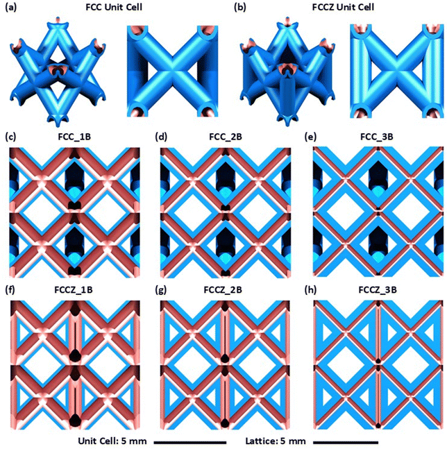
Face-centered cubic (FCC) and FCC with Z-struts/load-aligned struts (FCCZ) unit cell topologies were fabricated for this study (Fig. 1). These unit cell topologies were chosen by considering the solid-strut lattice literature that observes high compliance and low strength for the FCC topology, versus high stiffness and high strength for the FCCZ topology.53 Furthermore, FCC and FCCZ lattices do not contain unsupported horizontal struts, making their LPBF fabrication much easier when compared to complex topologies like the octet truss.33Table 1 summarizes the geometrical parameters for the AlSi10Mg hollow-strut lattice designs of this study. The number of cells is 6 × 6 × 6 (along the x, y, and z directions). This cell arrangement was chosen to be directly comparable to Ti–6Al–4V FCC and FCCZ HSLs,30 and solid-strut strut lattices. According to a recent literature review,53 six cells in each direction can be considered as an average cell number used by researchers. The cell size is fixed at 5 × 5 × 5 mm3, with a pore size of 3.5 × 3.5 × 3.5 mm3. The lattice dimensions by design are 31.5 × 31.5 × 31.5 mm3. The outer diameter (d) of each lattice hollow strut is 1.5 mm for both 45°- and 90°-inclined struts. This outer diameter is fixed for all designs.
| Unit cell type | Number of border scansa | Wall thickness (mm) | Strut outer diameter (mm) | Unit cell size (mm) | Cavity size (mm) | Strut incline (°) | Number of cells (x,y,z) | Lattice size (mm) | Relative density (%) |
|---|---|---|---|---|---|---|---|---|---|
| a Refer to the subsequent Fig. 2 for the implications of the number of border scans 1B, 2B, and 3B. | |||||||||
| FCC | 1B | 0.24 | 1.5 | 5 | 3.5 | 45 | (6,6,6) | 31.5 | 11.4 |
| FCC | 2B | 0.39 | 1.5 | 5 | 3.5 | 45 | (6,6,6) | 31.5 | 16.9 |
| FCC | 3B | 0.54 | 1.5 | 5 | 3.5 | 45 | (6,6,6) | 31.5 | 20.7 |
| FCCZ | 1B | 0.24 | 1.5 | 5 | 3.5 | 45, 90 | (6,6,6) | 31.5 | 13.7 |
| FCCZ | 2B | 0.39 | 1.5 | 5 | 3.5 | 45, 90 | (6,6,6) | 31.5 | 20.6 |
| FCCZ | 3B | 0.54 | 1.5 | 5 | 3.5 | 45, 90 | (6,6,6) | 31.5 | 25.5 |
Three inner channel diameters or wall thicknesses are considered. Our previous experimental studies found that for LPBF of Ti–6Al–4V hollow struts, to avoid powder occlusion, the minimum inner channel diameter should not be less than 4Dv(90).34 Since the LPBF of AlSi10Mg hollow struts is expected to be more challenging than that of Ti–6Al–4V hollow struts, we chose a minimum inner channel diameter of 6Dv(90) in our design. The other two inner channel diameters are chosen to be 10Dv(90) and 15Dv(90). The Dv(90) of the AlSi10Mg powder used in this study from SLM Solutions is 67.41 μm. These design considerations lead to our final designs described in Table 1 (three wall thicknesses: 0.24, 0.39, and 0.54 mm for both FCC and FCCZ lattices). The relative density varies from 11.4% to 25.5%. Fig. 1 displays each design listed in Table 1.
2.2. LPBF manufacture and powder material
An SLM Solutions 500HL system was used to fabricate all designs. The substrate material is aluminum alloy 5083. No support structures were used. The LPBF parameters were determined after a series of preliminary assessments, where AlSi10Mg standalone walls were first fabricated at laser scan speeds of 550–900 mm s−1 and laser powers of 150–250 W. Examining these walls using a Keyence VHX optical microscope determined that the laser power of 200 W and scan speed of 750 mm s−1 were optimum in geometrical consistency and structural stability. Table 2 lists the LPBF parameters chosen for this work, in line with an extensive study of the AlSi10Mg alloy using the SLM Solutions LPBF systems for solid-strut AlSi12Mg lattices.54 Importantly, the application of a zero-focus offset was pivotal in order to fabricate HSLs with the thinnest walls possible by LPBF.55 After fabrication, the lattice specimens were cooled in the powder bed to room temperature.| Spot size (μm) | Laser power (W) | Layer thickness (μm) | Scan speed (mm s−1) | Platform temperature (°C) | Focus offset (μm) | Single scan path width (μm) | Number of samples |
|---|---|---|---|---|---|---|---|
| 80 | 200 | 30 | 750 | 150 | 0 | ∼240 | 12 |
Spherical nitrogen-gas atomized AlSi10Mg powder supplied by SLM solutions was utilized. The main composition is Al–9.79Si–0.35Mg–0.11Fe (wt%), of which Cu, Mn, Cr, Ti, Ni, Mn, Sr, Zr, Sn, Pb, and Zn are each <0.01% and the other total is <0.15%. The powder has Dv(10) = 27.59 μm, Dv(50) = 43.08 μm, and Dv(90) = 67.41 μm. The theoretical density of ASi10Mg is taken as 2.67 g cm−3.53
2.3. Laser scan strategy
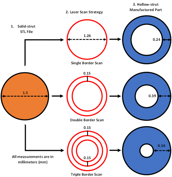
To fabricate these HSLs a constant border laser scan strategy was implemented, as it achieved success in Ti–6Al–4V hollow-strut lattice fabrication.30Fig. 2 shows the basic principles for the creation of each hollow strut with different inner diameters and wall thicknesses. The process starts from the same solid-strut STL file with the designed outer diameter (Fig. 2(1)) via different border scan paths (Fig. 2(2)) to create inner hollow channels with the designed wall thicknesses and diameters. It focuses on wall thickness where the scan paths always follow the slice contour without using the conventional hatching strategy. This strategy has proved effective for Ti–6Al–4V,30,33,34 but it has not been subjected to serious assessment in the fabrication of AlSi10Mg HSLs. It should be emphasized that the exact number of border scans can only be determined by experiments in relation to the wall thickness or channel diameter by design.As shown in Fig. 2, three laser scan strategies, namely single border scan (1B), double border scans (2B), and triple border scans (3B), are implemented. To achieve high-fidelity LPBF, each border scan is positioned inwards by 120 μm, to account for the width of the melt pool. Since the minimum wall thickness is 240 μm (for 1B), and the offset used between consecutive border scans is 150 μm (Fig. 2), the wall thickness is predicted to be 390 μm (for 2B), and 540 μm (for 3B).
2.4. Manufacturability characterization
A Bruker SKYSCAN X-ray microfocus computed tomography (μCT) machine was employed to examine the external and internal geometries of the hollow lattice struts. The operational parameters are listed in Table 3. One lattice specimen from each design in Table 1 was analyzed in detail by μCT. The nRECON shadow image reconstruction software (Bruker Pty Ltd) was used to reconstruct the cross-sectional slices acquired from the μCT angular projections through the object. The external and internal features were examined systematically layer by layer from the reconstructed lattice digital twins. To evaluate the mass and subsequent density, each hollow-strut lattice was weighed on a Digitech electronic scale with an accuracy of 0.001 g. To assess the fractography of the hollow-strut lattice specimens following compression testing, struts, and nodes were sectioned from the lattice and analyzed with scanning electron microscopy (SEM) using an FEI Quanta 200 SEM machine. An acceleration voltage of 30 kV and spot size of 5.0 μm were applied during the SEM.| Geometry | Source voltage (kV) | Source current (μA) | Voxel size (μm3) | Rotation α (°) | Rotation step α (°) | Filter |
|---|---|---|---|---|---|---|
| Hollow-strut lattice | 60 | 100 | 25 × 25 × 25 | 360 | 0.2 | Aluminium 1-mm thick |
2.5. Mechanical characterization
Quasi-static uniaxial compression was applied to the lattices to experimentally study their deformation behaviours and attain their mechanical properties. The samples were tested on an MTS 100 kN machine at room temperature. A strain rate of 1 × 10⁻³ s−1 was used according to the ISO standards.56 The lattice failure modes were recorded through progressive images taken by a high-speed camera at two-second intervals. The data output from this test provided a force versus displacement graph. The force was converted to stress by dividing against the lattice cross-sectional area in the XY plane prior to testing. The strain was calculated by dividing the displacement against the original lattice height (Z plane). To determine the unloading elastic modulus, the lattices were unloaded at both 2% and 4% strain to 0 MPa stress and subsequently loaded again while the samples remained in their elastic region.To assess the structural efficiency of the AlSi10Mg HSLs on the basis of architecture instead of material, their mechanical data was converted to relative density (ρ*/ρs), relative elastic modulus (E*/Es), and relative yield strength (σ*/σs) and plotted upon the Gibson–Ashby (G–A) model.57 The relative values, eliminate the material effects, by dividing the reported lattice property (denoted by superscript “*”) by the constituent bulk material property (subscript “s”). To calculate the relative properties, and also for numerical analysis, the density, yield strength, and elastic modulus of bulk LPBF AlSi10Mg are taken as 2.67 g cm−3,53 240 MPa58–60 and 70 GPa,53 respectively. Since the material properties depend on build orientation,58–60 these values can be treated as averages. We have used the datasets from two solid-strut lattice review papers to assess the efficiency of the manufactured hollow-strut lattice specimens.53,61 To ensure the datasets are up to date, we have divided the SS316l, Ti–6Al–4V, Inconel 625, and AlSi10Mg SSLs against recently reported LPBF datasheets for each respective material.62–67
2.6. Numerical modelling
The finite element method (FEM) was conducted to assess 1 × 1 × 2 lattices of the idealised CAD hollow-strut FCC and FCCZ topologies. The linear elastic FEM models were designed specifically to explain the internal and external stress distributions through the HSL topologies prior to yielding under compression, not to validate the mechanical property data measured from the lattice samples.The FEM assessment was conducted using the CATIA V6 advanced structural analysis tool (Dassault Systèmes 2020), with an isotropic elastic continuum material model for LPBF-printed AlSi10Mg.68 Tetrahedral continuum elements were implemented with an element size of 0.195 mm to achieve a high sensitivity mesh with 2.5–2.6 × 10⁵ elements. These parameters were chosen following a systematic mesh sensitivity study conducted with the maximum translation displacement values from FCC and FCCZ FEM models of varying element sizes. This assessment was designed to balance mesh sensitivity and computational time, however, a high displacement convergence (>90%) was still maintained for both the FCC and FCCZ hollow-strut lattice FEM models. The lattices were placed between two plates to evenly distribute the load. A compressive unit load of 100 N was applied to the upper surface of the plate, with translational restraints to prevent distortion in the upper plate. Furthermore, a fixed vertical boundary condition was placed at the bottom plate.
3. Manufacturability of AlSi10Mg HSLs
3.1. FCC HSLs
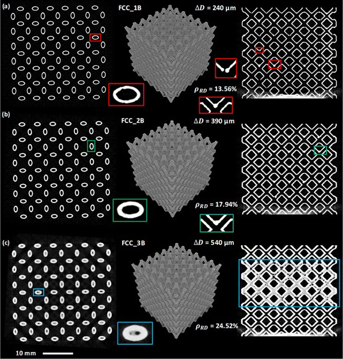
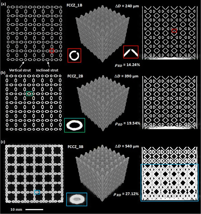
To assess the quality of the LPBF-fabricated FCC AlSi10Mg HSLs, each scan strategy was evaluated using μCT. The middle column of Fig. 3 shows the FCC HSLs reconstructed from the μCT data, where the resulting wall thicknesses (ΔD) are 240 μm from the single border scan (1B), 390 μm from the double border scans (2B), and 540 μm from the triple border scans (3B). Each reconstructed μCT lattice specimen was inspected layer by layer both horizontally and vertically. High manufacturable consistency was observed from each scan strategy. To display the structural details, the left-column images in Fig. 3 show horizontal cross-sections captured at the height of 18.25 mm in each lattice, while the right-column images are vertical cross-sections captured at a width of 15.75 mm from a side surface of each lattice. Specific sectional features are highlighted in Fig. 3 using small rectangles.The following observations are most notable from the systematic μCT characterization.
3.2. FCCZ HSLs
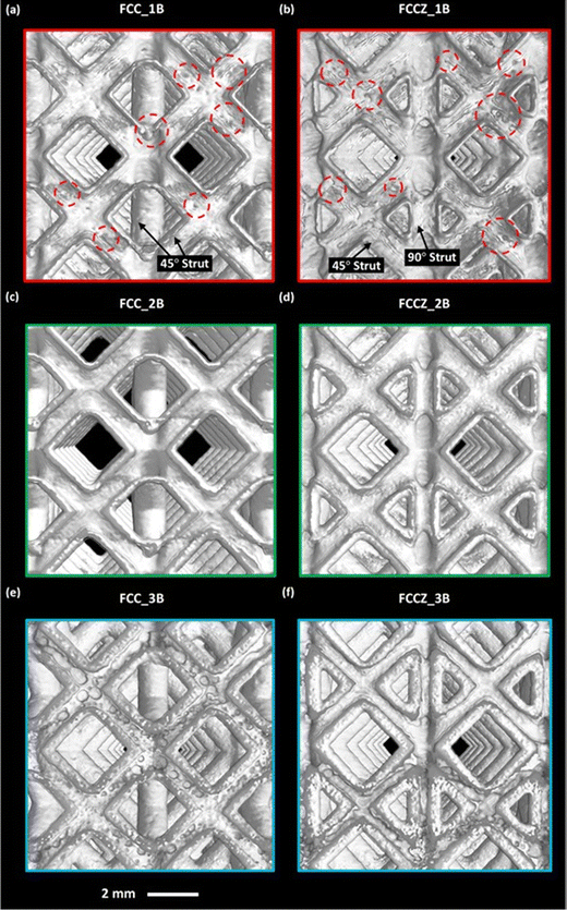
As pointed out earlier, the difference between FCC and FCCZ unit cells is that the latter comprises four extra vertical (90°) struts (the numbers of inclined struts and nodes are the same). For PBF AM of solid struts, vertical struts are the easiest to manufacture due to their perfect additive continuity. Therefore, it was expected that vertical hollow struts would be easily manufacturable as well. This was validated by the higher average gravimetric accuracy of the FCCZ specimens (98 ± 5%) versus the FCC specimens (88 ± 4%) when compared to the CAD models. Nevertheless, the vertical struts still observed the same defects as the inclined struts although these were less common. Fig. 4 and 5 display the detailed μCT observations of the manufactured FCCZ HSLs using the same three scan strategies.In general, the basic observations summarized above for FCC HSLs are all valid for FCCZ HSLs and will not be repeated. The double border scan strategy (FCCZ-2B) similarly resulted in high-fidelity successful fabrication (Fig. 4d and 5b). Special attention was therefore paid to the vertical hollow struts in each lattice. As shown in Fig. 4b and 5a (FCCZ_1B), volume shrinking also affected the geometry. For example, surface shrinkage cavities not only formed in the vertical hollow struts, but some also penetrated the wall thickness similar to Fig. 3a, indicating failed fabrication. The 240 μm wall thickness is thus insufficient for both vertical and inclined hollow struts of AlSi10Mg. The triple border scan (FCCZ_3B) resulted in powder occlusion not only in the inclined hollow struts (expected from Fig. 3c) but also in vertical hollow struts, as shown in Fig. 5c by the blue rectangles. Therefore, the 420 μm or 6Dv(90) wide internal channel is even insufficient to avoid powder occlusion in vertical struts (easier to remove powder) for AlSi10Mg. These observations confirm again that for LPBF of AlSi10Mg HSLs, it appears necessary to use 10Dv(90) wide and above inner channel diameters. No powder occlusion is an essential requirement for the design and PBF-AM of HSLs.
From the aforementioned μCT studies, the double border scan method (2B) together with the LPBF parameters selected can lead to high-fidelity LPBF of FCC and FCCZ AlSi10Mg HSLs.
4. Mechanical properties
Fig. 6a evaluates the relative yield strengths (σ*/σs) of the HSLs compared to the PBF literature data for Ti–6Al–4V, SS316L, CoCr, and AlSi10Mg SSLs via a Gibson–Ashby (G–A) plot. There are upper and lower limits for the G–A models as the empirically derived coefficients in the model expressions can vary from 0.1 to 1.0.69–72 As the limits are determined by empirically derived data, the upper limit of the G–A model plotted in Fig. 6a (with a coefficient value of 1.0) still remains difficult to reach for cellular metals, including solid-strut metal lattice metamaterials.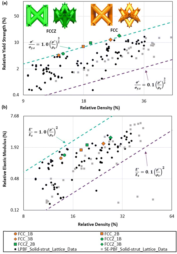 | ||
| Fig. 6 (a) Relative yield strength and (b) relative elastic moduli vs. relative density: comparison of AlSi10Mg hollow-strut lattices with solid-strut lattices of Ti–6Al–4V, Inconel 625, SS316L, CoCr, and AlSi10Mg (data source: ref. 53 and 61). (1B) single border scan (ΔD = 240 μm). (2B) double border scans (ΔD = 390 μm). (3B) triple border scans (ΔD = 540 μm). The blue and purple dotted lines indicate the upper and lower empirical limits of the Gibson–Ashby models, respectively. | ||
As observed from Fig. 6a, all the AlSi10Mg HSLs of this study are positioned at the upper empirical limit of the G–A model, indicating a very high strength efficiency comparable to the strongest reported SSLs. This is an important feature of HSLs and suggests that the G–A model for relative yield strength may require recalibration for stronger hollow-strut lattice metamaterials or topologies. Fig. 6b plots the relative elastic modulus data obtained from each hollow-strut lattice as a G–A chart against the PBF literature data for SSLs. The relative elastic moduli are consistent with the historic high-performance solid-strut lattice data, indicating no unique stiffness properties arising from the hollow-strut designs. The G–A model can still well predict the relative elastic moduli of these AlSi10Mg HSLs.
Interestingly, both the FCC and FCCZ topologies follow a similar trajectory on the G–A plots, Fig. 6. When comparing the specific yield strengths, the FCC lattices were 5.2%, 10.1%, and 13.7% weaker than the FCCZ lattices for the single, double, and triple scan paths. This indicates that as the wall thickness decreases and the size of the inner node volume increases, the efficiency of the Z-struts/load-aligned struts is significantly reduced. This is especially noticeable when compared to SSLs where LPBF-fabricated Inconel 625 FCC lattices were observed as 45.9% weaker than FCCZ lattices.73 Consequentially, it is likely that unit cell topologies with load-aligned struts are less efficient than pure bending-dominated topologies in the hollow-strut lattice space, due to their inefficient distribution of stress through the structure (discussed in Section 4.1.1). This also highlights the advantage of reinforcing the hollow-strut nodes with load-aligned struts to reduce this inefficiency.31
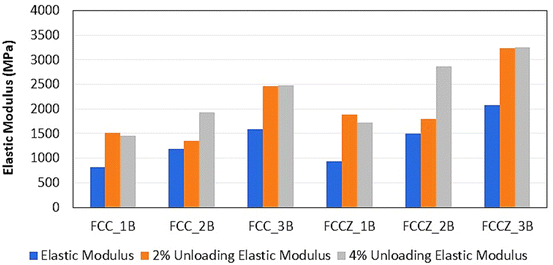
Aside from the normal elastic modulus, the unloading elastic modulus (unloaded at 2% and 4% strain) was also quantified. As pointed out by Ashby et al.,74 measuring the unloading elastic modulus better represents the performance of a cellular structure in service. Fig. 7 compares the elastic moduli of each lattice with and without unloading. It provides an indication of how hollow-strut lattice metamaterials will behave in a functional setting that includes repetitive loading and unloading. The double and triple border scan strategies resulted in a robust response, where the samples exhibited an improved elastic modulus after loading and unloading at 2% and 4% strain. Conversely, the single border scan led to a different response, where the samples showed an improved elastic modulus after loading and unloading at 2% strain but failed to show any further improvement after loading and unloading at 4% strain. This further validates the high structural integrity of the wall thicknesses with double laser border scans.
Even with their challenging fabrication, the relative yield strengths of AlSi10Mg HSLs are positioned at the upper empirical limit (Fig. 6a), similar to Ti–6Al–4V HSLs.30,38 Furthermore, when comparing the correlation coefficient for each data set, the Ti–6Al–4V and AlSi10Mg HSLs observed an almost perfect correlation of R2 = 0.99 for both the FCC and FCCZ topologies. This indicates that LPBF AlSi10Mg can fabricate structurally efficient HSLs of a similar standard to LPBF Ti–6Al–4V HSLs. Considering the lower material cost of AlSi10Mg, hollow-strut aluminium alloy lattices may be considered as potential replacements for certain applications of titanium HSLs. The high correlation between the AlSi10Mg and Ti–6Al–4V specimens indicates that the structural efficiency of the HSL is topology dependent, not material dependent. This is a major advantage of comparing their relative properties (Gibson–Ashby method), as this allows the focus to be on the lattice architecture rather than the lattice constituent materials. Consequentially, any type of metal HSLs fabricated through LPBF should exhibit similar results.
Complementary to Fig. 6a and 8 focuses on the relative yield strength and absolute yield strength of the high-quality FCC_2B and FCCZ_2B AlSi10Mg HSLs compared to Ti–6Al–4V and SS316L SSLs of similar relative densities (17–20%). Although LPBF AlSi10Mg as a bulk material is weaker than LPBF Ti–6Al–4V and LPBF SS316L,75,76 the relative yield strength of the hollow-strut AlSi10Mg lattices far exceeds that of each solid-strut reference lattice metamaterial (Fig. 8a). Furthermore, their absolute yield strength is comparable to those of the solid-strut reference lattices, even with much lower absolute densities (0.48–0.52 vs. 0.74–1.33 g cm−3, Fig. 8b). Considering their low material cost, high corrosion resistance, and low density, Al alloy HSLs may be considered as potential replacements for certain applications of titanium and stainless steel SSL metamaterials.
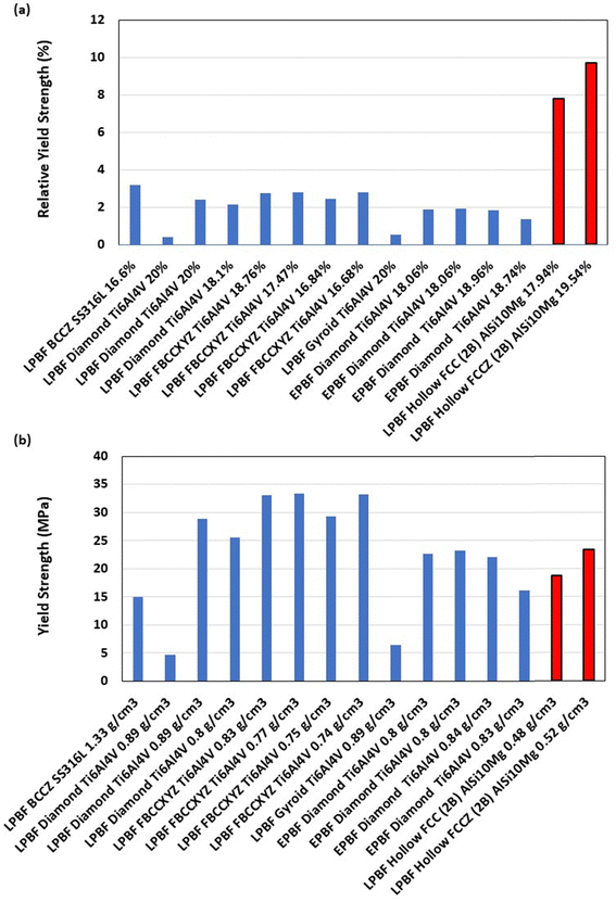 | ||
| Fig. 8 Comparison of relative yield strength (a) and absolute yield strength (b) between FCC_2B and FCCZ_2B AlSi10Mg hollow-strut lattices and Ti–6Al–4V and SS316L solid-strut lattices of similar relative density (17–20%).53,54,78–82 The name of each data point on the X-axis denotes “unit cell topology, material, relative or absolute density”. Error bars were not included as the standard deviation between samples was negligible. | ||
The underlying reasons for the superior mechanical properties of HSLs to their solid-strut counterparts have been discussed in recent studies.17,30,31,38 It is mainly due to their hollow strut sections that exhibit higher resistance to bending than solid-strut lattices, resulting in greater strength and stiffness. More specifically, at the same strut length and relative density, the actual strut cross-sectional area remains approximately the same for both the solid and hollow struts.77 This condition requires that:
| dSolid2 = dOuter2 − dInner2 | (1) |
Under this condition, the second moment of inertia (I) of the hollow strut (Ihollow![[thin space (1/6-em)]](https://www.rsc.org/images/entities/char_2009.gif) strut) given by eqn (2) is always greater than that of the solid strut (ISolid
strut) given by eqn (2) is always greater than that of the solid strut (ISolid![[thin space (1/6-em)]](https://www.rsc.org/images/entities/char_2009.gif) strut) given by eqn (3):
strut) given by eqn (3):
Ihollow![[thin space (1/6-em)]](https://www.rsc.org/images/entities/char_2009.gif) strut = π(dOuter4 − dInner4)/64ISolid strut = πdSolid4/643 strut = π(dOuter4 − dInner4)/64ISolid strut = πdSolid4/643 | (2) |
 | (3) |
| S = 2I/d | (4) |
5. Deformation response
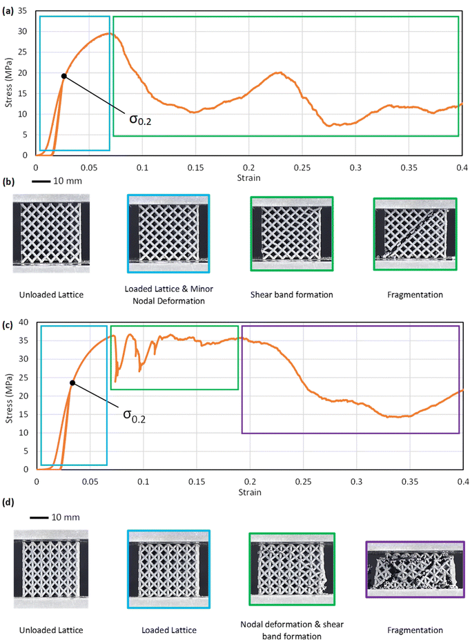
To gain insight into the deformation behaviours and failure modes of the AlSi10Mg HSLs, the high-quality FCC_2B and FCCZ_2B HSLs were examined. Fig. 9(a and b) shows a closer inspection of their stress–strain curves in relation to their corresponding physical status obtained using a high-speed camera.The FCC_2B AlSi10Mg HSLs followed similar deformation behaviours commonly observed for conventional SSLs under compression.54,73 This included bending-dominated deformation with increasing loading, which generated moments at the nodes with minor nodal deformation in the initial stages (Fig. 9a and b). This deformation continued to develop with increasing loading, as indicated by the gradient softening until the first peak strength (FPS) was reached. No obvious lattice failure was observed up to this stage (blue box, Fig. 9b). The main deformation events after reaching the FPS are distortion along the 45° diagonal, which represents the maximum shear stress direction under uniaxial compression when the lattice is composed of a sufficient number of unit-cell layers (e.g. ≥5;83 it is 6 in this work). However, global fracture of the struts along the 45° diagonal (the first green box in Fig. 9b) commenced immediately after reaching the FPS, followed by intensive shear-dominated fracture along the 45° diagonal (the second green box in Fig. 9b), which corresponds to the end of the drop in FPS. Distortion occurred to most lattice unit cells by this stage, irrespective of their positions. The second peak strength recorded in Fig. 9a arises from the compression of the remaining half lattice below the 45° diagonal shown in the second green box of Fig. 9b. However, due to the prior disintegration of the lattice along the 45° diagonal, this part of the lattice deformation may only have limited value in practice.
The FCCZ_2B AlSi10Mg HSLs showed a mixed failure mode. Similarly, no visible deformation or fracture was observed in the lattice before reaching the FPS (see the blue box in Fig. 9c and d). Deformation and local fracture of strut nodes connected to the Z-axis started to occur immediately after reaching the FPS while shear deformation occurred along different directions at the same time (see the green box in Fig. 9d). However, all the nodes connected exclusively to the inclined struts exhibited much less deformation. After an initial stage of node fracture, shown as multi-dips in the stress–strain curve (the green box in Fig. 9c), a plateau strength was reached up to ∼22% compressive strain. The lattice structure then underwent pronounced nodal fracture or fragmentation along the compression direction and some shear prevalent directions, as shown in the violet box of Fig. 9d.
FCC HSLs were observed to undergo nodal deformation before global fracture through the 45° shear planes (Fig. 9). This deformation response is well documented for many lattice topologies under uniaxial compression both experimentally84–90 and numerically.54,73,84,91,92 This is because the 45° planes are where the maximum slippage can occur between the struts and nodes due to the maximum shear stress along the 45° diagonal. As for the FCCZ HSLs, the vertical struts act as column beams, which directly resist compression, while the inclined struts reinforce the vertical struts against column bending and strut hinging at the nodes. However, LPBF AlSi10Mg is not highly ductile (5–8% tensile ductility93,94), due to its high Si content, which exists as eutectic silicon crystals (the solubility of Si in α-Al is negligible). As a result, nodal fragmentation occurred at the FPS (Fig. 9c), followed by increased nodal fragmentation with increasing compressive strain to ∼8%. This differs from the deformation of solid nodes, which observes reduced stress at the core but larger stress at the node/strut interconnection points preventing fragmentation through the solid nodes.54,73
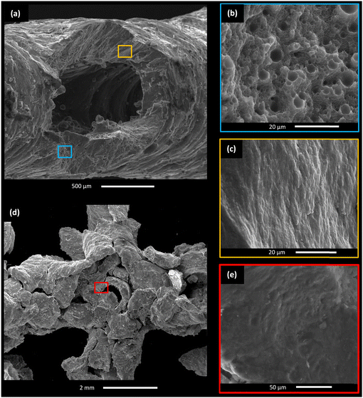
The node fracture features for FCC_2B lattices are shown in Fig. 10. Pores are common (Fig. 10a and b), as observed for other LPBF AlSi10Mg materials.93,94 According to Weingarten et al.,95 about 96% of the pores in LPBF AlSi10Mg contain hydrogen due to the moisture in the powder, which reacts with Al during LPBF, resulting in the melt pool containing absorbed hydrogen.95 In addition, the unavoidable residual nitrogen gas (atomization gas) in the AlSi10Mg powder may have also contributed to the porosity. Eliminating these pores through control of powder moisture should help to further enhance the strength and ductility of AlSi10Mg HSLs. The fractographs display limited shallow dimples in the matrix between the gas pores (Fig. 10b) and large flat fracture regions (Fig. 10c), coinciding with the low compressive strain (∼7%, Fig. 9a) observed at the FPS.
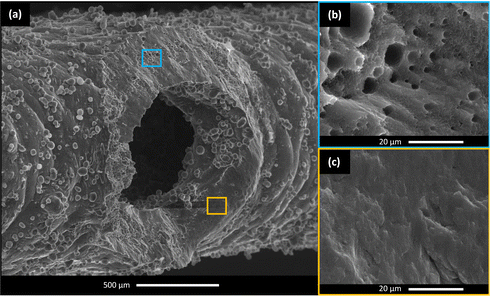 | ||
| Fig. 10 Nodal fracture features in FCC_2B AlSi10Mg hollow-strut lattices (a) with closer views of selected regions from (a): blue rectangle (b) and yellow rectangle (c). | ||
Two types of nodal fractures were observed in the FCCZ_2B AlSi10Mg HSLs. One is the nodal fracture of the inclined struts (without connection to vertical struts), which is akin to that shown in Fig. 10, displaying a mixture of pores, limited shallow dimples, and large flat fracture regions (Fig. 11a–c). The other is nodal fragmentation as exemplified in Fig. 11d and e, which occurred in the nodes connected to the vertical struts due to them being the main load-bearing structures in the compression direction.
6. Finite element modelling (FEM) of stress distribution
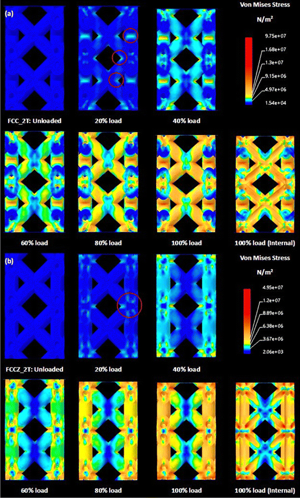
The deformation behaviour of the experimental FCC and FCCZ HSLs, shown in Fig. 9, coincides with the stress distributions characterized by the FCC_2B and FCCZ_2B 2 × 2 × 1 FEM models, exhibited in Fig. 12. The HSLs with double border (2B) scans were chosen as this laser scan strategy produced specimens most representative of the idealised CAD models.During initial loading, the experimental FCC lattices observed only minor node deformation from direct compressive force. However, hinging is visible in the non-axially aligned struts that comprise the FCC topology (Fig. 9b). This validates the FCC FEM results that observe stress concentrations proliferating from the regions where the struts adjoin at the node (Fig. 12a). This deformation response and the clear movement of the inclined struts indicate a bending dominated deformation response, atypical of solid-strut FCC lattices,53 but consistent with Ti–6Al–4V hollow-strut FCC lattices.30
During compression of the experimental FCCZ lattices, the nodes interconnected to the load-aligned struts were observed to ovalize and deform before the struts would observe any deformation as shown in Fig. 9d. These nodes were points of initial fracture, with the entire structure fragmenting following their deformation. This localized failure validates the stress distributions observed within the FCCZ FEM model (red circles Fig. 12b), where stress is similarly concentrated at the inner node walls connected to the load-aligned struts, before proliferating through these struts. These isolated stress concentrations could well facilitate a premature lattice failure and prevent the topology from observing a homogenous stress distribution.
The numerical analysis also provides insight into the high relative yield strength of the hollow-strut FCC specimens and the inefficient strength of the FCCZ specimens, highlighted by their consistent placement in Fig. 6a. For the FCC assessment, as highlighted in Fig. 12a, the stress is distributed from the joint regions through most of the unit cell, loading the lattice array homogenously. This distribution improves the structural efficiency (observed with the FCC topologies), as more material is applied to resist the compressive load. This hypothesis is further solidified by the internal view of the FCC FEM model during loading, which observes far less stress concentrations isolated to the inner node walls when compared to the FCCZ unit cells (Fig. 12b).
The numerical analysis of the FCCZ in Fig. 12b observes stress isolated to the node regions, and this only distributes to the load-aligned struts after the nodes are withstanding far higher stress. Consequentially, it is likely that the hollow struts will not achieve their predicted efficiency, as the nodes will reach a critical failure point far before the strut section properties may have any significant effect. This is supported by the experimental results in Fig. 9d as the nodes clearly fail while the load-aligned struts maintain their stability with minimal signs of deformation before global fragmentation. Furthermore, the inefficient stress distribution of the hollow-strut FCCZ topology results in far more zero-stress regions than the FCC topology (Fig. 12). These structural limitations culminate in the FCCZ topology failing to reach its expected potential, as observed by its placement on the Gibson Ashby model (Fig. 6a), in comparison to the FCC topology (which is traditionally weaker53).
The series of failure modes experienced by the FCCZ topology is unique to LPBF-fabricated HSLs, and it has only been reported in Ti–6Al–4V specimens with load-aligned struts so far. This indicates that their deformation behaviours are likely more topology-dependent or less material-dependent.30,31 However, more load-aligned topologies should be assessed to consolidate these claims.
7. Summary
Intricate AlSi10Mg HSLs with high-fidelity internal and external profiles and negligible trapped powder can be fabricated through LPBF by using a simple and efficient double border scan strategy. However, a minimum wall thickness of 0.4 mm to ensure high wall integrity and a minimum internal diameter of 0.7 mm to avoid powder occlusion are required.The FCC and FCCZ AlSi10Mg HSLs exhibited high relative yield strength at the upper empirical limit of the Gibson–Ashby plot, superior to SSLs of Ti–6Al–4V, AlSi10Mg, and SS316L of equivalent relative density, while their absolute yield strength is also comparable (even with lower densities). Considering their low material cost, good corrosion resistance, and low density, AlSi10Mg HSLs are expected to find good niche applications.
When comparing the relative yield strength of the AlSi10Mg hollow-strut lattice specimens with reported Ti–6Al–4V hollow-strut lattices of equivalent topology, an almost perfect correlation coefficient of R2 = 0.99 was observed. This high correlation indicates that the high structural efficiency of the hollow-strut lattices is topology dependent not material dependent.
Author contributions
J. N.: investigation, characterization, critical analysis, compilation, draft, review. M. L.: review, supervision, critical analysis, funding acquisition. M. B.: conceptualization, critical analysis, review, supervision, funding acquisition. M. Q.: conceptualization, critical analysis, draft, review, supervision, funding acquisition.Conflicts of interest
The authors declare that there is no conflict of interest.Acknowledgements
This project was funded by the Australian Research Council (ARC) through DP200102666. The authors acknowledge the scientific and technical support of the RMIT Centre for Additive Manufacturing (RCAM) and the RMIT Microscopy and Microanalysis Facility (RMMF), especially the technical staff consisting of Simon Brudler, Paul Spithill, and Chaitali Dekiwadia.References
- S. Morankar, A. S. Singaravelu, S. Niverty, Y. Mistry, C. A. Penick, D. Bhate and N. Chawla, Tensile and fracture behavior of silica fibers from the Venus Flower Basket (Euplectella Aspergillum), Int. J. Solids Struct., 2022, 253, 111622 CrossRef CAS.
- S. K. Morankar, Y. Mistry, D. Bhate, C. A. Penick and N. Chawla, In situ investigations of failure mechanisms of silica fibers from the Venus Flower Basket (Euplectella Aspergillum), Acta Biomater., 2023, 162, 304–311 CrossRef CAS PubMed.
- H. F. Archila-Santos, M. P. Ansell and P. Walker, Low carbon construction using Guadua bamboo in Colombia, Key Eng. Mater., 2012, 517, 127–134 Search PubMed.
- T. N. Sullivan, B. Wang, H. D. Espinosa and M. A. Meyers, Extreme lightweight structures: Avian feathers and bones, Mater. Today, 2017, 20, 377–391 CrossRef.
- A. Ghazlan, T. Ngo, T. Nguyen, S. Linforth and T. Van Le, Uncovering a high-performance bio-mimetic cellular structure from Trabecular Bone, Sci. Rep., 2020, 10, 14247 CrossRef CAS PubMed.
- H. Zhong, R. Das, J. Gu and M. Qian, Low-density, high-strength metal mechanical metamaterials beyond the Gibson-Ashby model, Materials Today, 2023, 68, 96–107 CrossRef CAS.
- M. Bici, S. Brischetto, F. Campana, C. G. Ferro, C. Seclì, S. Varetti, P. Maggiore and A. Mazza, Development of a multifunctional panel for aerospace use through SLM additive manufacturing, Procedia CIRP, 2018, 67, 215–220 CrossRef.
- Ö. C. Akbay, E. Bahçe, A. Uysal and İ. Gezer, Productıon and cleaning of lattice structures used in the space and aerospace industry with Metal Additive Manufacturing Method, J. Mater. Eng. Perform., 2022, 31, 6310–6321 CrossRef.
- S. Mantovani, G. Campo and M. Giacalone, Steering column support topology optimization including lattice structure for metal additive manufacturing, Proc. Inst. Mech. Eng., Part C, 2020, 236, 10645–10656 CrossRef.
- Q. Feng, Q. Tang, Z. Liu, Y. Liu and R. Setchi, An investigation of the mechanical properties of metallic lattice structures fabricated using selective laser melting, Proc. Inst. Mech. Eng., Part B, 2016, 232, 1719–1730 CrossRef.
- E. Alabort, D. Barba and R. C. Reed, Design of metallic bone by additive manufacturing, Scr. Mater., 2019, 164, 110–114 CrossRef CAS.
- N. Soro, E. G. Brodie, A. Abdal-hay, A. Q. Alali, D. Kent and M. S. Dargusch, Additive manufacturing of biomimetic titanium-tantalum lattices for biomedical implant applications, Mater. Des., 2022, 218, 110688 CrossRef CAS.
- S. Catchpole-Smith, R. R. J. Sélo, A. W. Davis, I. A. Ashcroft, C. J. Tuck and A. Clare, Thermal conductivity of TPMS lattice structures manufactured via laser powder bed fusion, Addit. Manuf., 2019, 30, 100846 Search PubMed.
- U. Sajjad, T. Rehman, M. Ali, C. W. Park and W.-M. Yan, Manufacturing and potential applications of lattice structures in thermal systems: A comprehensive review of recent advances, Int. J. Heat Mass Transf., 2022, 198, 123352 CrossRef.
- H. Wang, Y. Chen and D. W. Rosen, A hybrid geometric modeling method for large scale conformal cellular structures, in Volume 3: 25th Computers and Information in Engineering Conference, Parts A and B, 2005 Search PubMed.
- J. Brennan-Craddock, The investigation of a method to generate conformal lattice structures for additive manufacturing, PhD thesis, Loughborough University, 2011 Search PubMed.
- J. Noronha, M. Qian, M. Leary, E. Kyriakou and M. Brandt, Hollow-walled lattice materials by additive manufacturing: Design, manufacture, properties, applications and challenges, Curr. Opin. Solid State Mater. Sci., 2021, 25, 100940 CrossRef.
- L. Salari-Sharif, S. W. Godfrey, M. Tootkaboni and L. Valdevit, The effect of manufacturing defects on compressive strength of Ultralight Hollow microlattices: A data-driven study, Addit. Manuf., 2018, 19, 51–61 CAS.
- T. Schaedler, A. Jacobsen, A. Torrents, A. Sorensen, J. Lian, J. Greer, L. Valdevit and W. B. Carter, Ultralight Metallic Microlattices, Science, 2011, 334, 962–965 CrossRef CAS PubMed.
- X. Zheng, H. Lee, T. H. Weisgraber, M. Shusteff, J. DeOtte, E. B. Duoss, J. D. Kuntz, M. M. Biener, Q. Ge, J. A. Jackson, S. O. Kucheyev, N. X. Fang and C. M. Spadaccini, Ultralight, ultrastiff mechanical metamaterials, Science, 2014, 344, 1373–1377 CrossRef CAS PubMed.
- P. K. Kanaujia, M. A. bin Ramezan, X. Y. Yap, Y. Song, Z. Du, C. L. Gan, Y. C. Lam and C. Q. Lai, Mechanical response of lightweight hollow truss metal oxide lattices, Materialia, 2019, 8, 100439 CrossRef CAS.
- J. Xu, Y. Gao, H. Huang, Q. Yang, L. Guo and L. Jiang, Diamond-structured hollow-tube lattice NI materials via 3D printing, Sci. China: Chem., 2016, 59, 1632–1637 CrossRef CAS.
- L. R. Meza and J. R. Greer, Mechanical characterization of Hollow Ceramic nanolattices, J. Mater. Sci., 2013, 49, 2496–2508 CrossRef.
- L. C. Montemayor, L. R. Meza and J. R. Greer, Design and fabrication of hollow rigid nanolattices via two-photon lithography, Adv. Eng. Mater., 2013, 16, 184–189 CrossRef.
- J. Shi and L. Liu, Creating hollow microlattice materials reinforced by carbon nanotubes for improved mechanical properties, Mater. Lett., 2019, 240, 205–208 CrossRef CAS.
- Y. Liu, T. A. Schaedler, A. J. Jacobsen and X. Chen, Quasi-static energy absorption of hollow microlattice structures, Composites, Part B, 2014, 67, 39–49 CrossRef.
- E. C. Clough, J. Ensberg, Z. C. Eckel, C. J. Ro and T. A. Schaedler, Mechanical performance of hollow tetrahedral truss cores, Int. J. Solids Struct., 2016, 91, 115–126 CrossRef CAS.
- J. Noronha, M. Leary, M. Qian, E. Kyriakou and M. Brandt, Geometrical parameters and mechanical properties of ti6al4v hollow-walled lattices, Mater. Sci. Eng., A, 2022, 840, 142667 CrossRef CAS.
- Z. Zhang, L. Zhang, B. Song, Y. Yao and Y. Shi, Bamboo-inspired, simulation-guided design and 3D printing of light-weight and high-strength mechanical metamaterials, Appl. Mater. Today, 2022, 26, 101268 CrossRef.
- J. Noronha, J. Rogers, M. Leary, E. Kyriakou, S. B. Inverarity, R. Das, M. Brandt and M. Qian, Ti-6Al-4V hollow-strut lattice materials by laser powder bed fusion, Addit. Manuf., 2023, 72, 103637 CAS.
- J. Noronha, J. Dash, M. Leary, D. Downing, E. Kyriakou, M. Brandt and M. Qian, Node-reinforced hollow-strut metal lattice materials for higher strength, Scr. Mater., 2023, 234, 115547 CrossRef CAS.
- M. Zhao, X. Li, D. Z. Zhang and W. Zhai, Geometry effect on mechanical properties and elastic isotropy optimization of bamboo-inspired lattice structures, Addit. Manuf., 2023, 64, 103438 Search PubMed.
- J. Noronha, M. Qian, M. Leary, E. Kyriakou, A. Almalki, S. Brudler and M. Brandt, Additive manufacturing of TI-6AL-4V horizontal hollow struts with submillimetre wall thickness by laser powder bed fusion, Thin-Walled Struct., 2022, 179, 109620 CrossRef.
- J. Noronha, M. Qian, M. Leary, E. Kyriakou, S. Brudler and M. Brandt, Manufacturability of ti-6al-4v hollow-walled lattice struts by laser powder bed fusion, JOM, 2021, 73, 4199–4208 CrossRef.
- L. Xiao, G. Feng, S. Li, K. Mu, Q. Qin and W. Song, Mechanical characterization of additively-manufactured metallic lattice structures with hollow struts under static and dynamic loadings, Int. J. Impact Eng., 2022, 169, 104333 CrossRef.
- C. Bonatti and D. Mohr, Large deformation response of additively-manufactured FCC metamaterials: From octet truss lattices towards continuous shell mesostructures, Int. J. Plast., 2017, 92, 122–147 CrossRef.
- J. Noronha, J. Dash, J. Rogers, M. Leary, M. Brandt and M. Qian, Titanium Multi-Topology Metamaterials with Exceptional Strength, Adv. Mater., 2024, 2308715 CrossRef PubMed.
- J. Noronha, H. Zhong, M. Leary, M. Brandt and M. Qian, Hollow-strut metal lattice materials: A viable alternative to solid-strut lattice materials, Proceedings of the Advances in Additive Manufacturing with Powder Metallurgy, 2023, pp. 832–842 Search PubMed.
- H. Y. Ma, J. C. Wang, P. Qin, Y. J. Liu, L. Y. Chen, L. Q. Wang and L. C. Zhang, Advances in additively manufactured titanium alloys by powder bed fusion and directed energy deposition: Microstructure, defects, and mechanical behavior, J. Mater. Sci. Technol., 2024, 183, 32–62 CrossRef.
- J. Wang, R. Zhu, Y. Liu and L. Zhang, Understanding melt pool characteristics in laser powder bed fusion: An overview of single- and multi-track melt pools for process optimization, Adv. Powder Mater., 2023, 2, 100137 CrossRef.
- S. Ricci, G. Testa, G. Iannitti and A. Ruggiero, Laser powder bed fusion of alsi10mg alloy: Numerical investigation on the Temperature Field Evolution, Forces Mech., 2022, 8, 100109 CrossRef.
- Z. Li, B. Q. Li, P. Bai, B. Liu and Y. Wang, Research on the Thermal Behaviour of a Selectively Laser Melted Aluminium Alloy: Simulation and Experiment, Materials, 2018, 11, 1172 CrossRef PubMed.
- B. Liu, B. Q. Li, Z. Li, P. Bai, Y. Wang and Z. Kuai, Numerical investigation on heat transfer of multi-laser processing during selective laser melting of AlSi10Mg, Results Phys., 2019, 12, 454–459 CrossRef.
- Y. Du, X. You, F. Qiao, L. Guo and Z. Liu, A model for predicting the temperature field during selective laser melting, Results Phys., 2019, 12, 52–60 CrossRef.
- P. Wei, Z. Wei, Z. Chen, Y. He and J. Du, Thermal behavior in single track during selective laser melting of AlSi10Mg Powder, Appl. Phys. A, 2017, 123, 604 CrossRef.
- M. Mohr, R. Wunderlich, R. Novakovic, E. Ricci and H. J. Fecht, Precise measurements of thermophysical properties of liquid Ti–6Al–4V (Ti64) alloy on board the international space station, Adv. Eng. Mater., 2020, 22, 2000169 CrossRef CAS.
- H. Wang, S. Yang and B. Wei, Density and structure of undercooled liquid titanium, Chin. Sci. Bull., 2012, 57, 719–723 CrossRef CAS.
- T. Song, Z. Chen, X. Cui, S. Lu, H. Chen, H. Wang, T. Dong, B. Qin, K. C. Chan, M. Brandt, X. Liao, S. P. Ringer and M. Qian, Strong and ductile titanium–oxygen–iron alloys by additive manufacturing, Nature, 2023, 618, 63–68 CrossRef CAS PubMed (Supplementary Information Section 2.3).
- M. P. Behera, T. Dougherty, S. Singamneni and K. D. Silva, Selective laser melting of aluminium metal-matrix composites and the challenges, Mater. Today Proc., 2020, 33, 5729–5733 CrossRef.
- N. T. Aboulkhair, N. M. Everitt, I. Ashcroft and C. Tuck, Reducing porosity in AlSi10Mg parts processed by selective laser melting, Addit. Manuf., 2014, 1–4, 77–86 Search PubMed.
- M. Qian, W. Xu, M. Brandt and H. P. Tang, Additive Manufacturing and postprocessing of ti-6al-4v for superior mechanical properties, MRS Bull., 2016, 41, 775–784 CrossRef CAS.
- M. Yan, P. Yu, G. B. Schaffer and M. Qian, Secondary phases and interfaces in a nitrogen-atmosphere sintered al alloy: Transmission electron microscopy evidence for the formation of ALN during Liquid Phase Sintering, Acta Mater., 2010, 58, 5667–5674 CrossRef CAS.
- T. Maconachie, M. Leary, B. Lozanovski, X. Zhang, M. Qian, O. Faruque and M. Brandt, SLM lattice structures: Properties, performance, applications and challenges, Mater. Des., 2019, 183, 108137 CrossRef.
- M. Brandt, M. Mazur and M. Leary, Mechanical properties of Ti6Al4V and AlSi12Mg lattice structures manufactured by selective laser melting (SLM), Laser Additive Manufacturing, Elsevier, Woodhead, Amsterdam, 2017, pp. 119–161 Search PubMed.
- B. Liu, G. Fang, L. Lei and W. Liu, Experimental and numerical exploration of defocusing in Laser Powder Bed Fusion (LPBF) as an effective processing parameter, Opt. Laser Technol., 2022, 149, 107846 CrossRef CAS.
- ISO, 13314 Compression test for porous and cellular metals, International Organization for Standardization, Geneva, Switzerland, 2011 Search PubMed.
- L. J. Gibson, The elastic and plastic behaviour of cellular materials, PhD thesis, University of Cambridge, Cambridge, 1981.
- D. Murphy, O. Fashanu, M. Spratt, J. Newkirk and K. Chandrashekhara, Compressive and Bending Performance of Selectively Laser Melted AlSi10Mg Structures, in Proceedings of the International Solid Freeform Fabrication Symposium, 2019 Search PubMed.
- E. Sert, L. Hitzler, S. Hafenstein, M. Merkel, E. Werner and A. Öchsner, Tensile and compressive behaviour of additively manufactured alsi10mg samples, Prog. Addit. Manuf., 2020, 5, 305–313 CrossRef.
- L. Hitzler, N. Schoch, B. Heine, M. Merkel, W. Hall and A. Öchsner, Compressive behaviour of additively manufactured alsi10mg, Materwiss. Werksttech., 2018, 49, 683–688 CrossRef CAS.
- X. Z. Zhang, M. Leary, H. P. Tang, T. Song and M. Qian, Selective electron beam manufactured ti-6al-4v lattice structures for orthopedic implant applications: Current status and outstanding challenges, Curr. Opin. Solid State Mater. Sci., 2018, 22, 75–99 CrossRef CAS.
- EOS StainlessSteel 316L Material Data Sheet, Electro Optical Systems, Munich, Germany, 2022. Available online: https://www.eos.info/03_system-related-assets/material-related-contents/metal-materials-and-examples/metal-material-datasheet/stainlesssteel/material_datasheet_eos_stainlesssteel_316l_en_web.pdf.
- Material data sheet EOS StainlessSteel 316L, Electro Optical Systems, Munich, Germany, 2014. Available online: https://www.in3dtec.com/wp-content/uploads/2020/09/StainlessSteel316L-Data-sheet.pdf.
- Material Data Sheet Ti-Alloy Ti6Al4V ELI (Grade 23), SLM Solutions, Lübeck, Germany. Available online: https://www.slm-solutions.com/fileadmin/Content/Powder/MDS/MDS_Ti-Alloy_Ti6Al4V__ELI_0719_EN.pdf.
- Material Data Sheet Ni-Alloy IN625, SLM Solutions, Lübeck, Germany. Available online: https://www.slm-solutions.com/fileadmin/Content/Powder/MDS/MDS_Ni-Alloy_IN625_0819_EN.pdf.
- EOS Aluminium AlSi10Mg Material Data Sheet, Electro Optical Systems, Munich, Germany, 2022. Available online: https://www.eos.info/03_system-related-assets/material-related-contents/metal-materials-and-examples/metal-material-datasheet/aluminium/material_datasheet_eos_aluminium-alsi10mg_en_web.pdf.
- Material data sheet EOS Aluminium AlSi10Mg, Electro Optical Systems, Munich, Germany, 2014. Available online: https://f.hubspotusercontent30.net/hubfs/6249387/Material%20Data%20Sheets/EOS_Aluminium_AlSi10Mg_en.pdf.
- Aluminum (alsi10mg): Powder bed fusion 3D printing services, Proto3000. https://proto3000.com/materials/dmls-aluminum-2/, 2014 (accessed 17 August 2023).
- L. Gibson and M. Ashby, Cellular solids, Cambridge University Press, Cambridge, 1999, pp. 52–92 Search PubMed.
- M. F. Ashby, Hybrid materials to expand the boundaries of material-property space, J. Am. Ceram. Soc., 2011, 94, 3–14 CrossRef.
- L. J. Gibson, Modelling the mechanical behavior of cellular materials, Mater. Sci. Eng., A, 1989, 110, 1–36 CrossRef.
- M. Ashby, The properties of foams and lattices, Philos. Trans. R. Soc. A., 2005, 364, 15–30 CrossRef PubMed.
- M. Leary, M. Mazur, H. Williams, E. Yang, A. Alghamdi, B. Lozanovski, X. Zhang, D. Shidid, L. Farahbod-Sternahl, G. Witt, I. Kelbassa, P. Choong, M. Qian and M. Brandt, Inconel 625 lattice structures manufactured by Selective Laser Melting (SLM): Mechanical properties, deformation and failure modes, Mater. Des., 2018, 157, 179–199 CrossRef CAS.
- M. F. Ashby, A. G. Evans, N. A. Fleck, L. J. Gibson, J. W. Hutchinson and H. Wadely, Metal Foams: A Design Guide, Butterworth-Heinemann - an imprint of Elsevier, Boston etc., 2009, p. 45 Search PubMed.
- W. Pan, Z. Ye, Y. Zhang, Y. Liu, B. Liang and Z. Zhai, Research on microstructure and properties of alsi10mg fabricated by selective laser melting, Materials, 2022, 15, 2528 CrossRef CAS PubMed.
- A. Röttger, J. Boes, W. Theisen, M. Thiele, C. Esen, A. Edelmann and R. Hellmann, Microstructure and mechanical properties of 316l austenitic stainless steel processed by different SLM devices, Int. J. Adv. Manuf. Technol., 2020, 108, 769–783 CrossRef.
- H. Z. Zhong, T. Song, C. W. Li, R. Das, J. F. Gu and M. Qian, Understanding the superior mechanical properties of hollow-strut metal lattice materials, Scr. Mater., 2023, 228, 115341 CrossRef CAS.
- S. McKown, Y. Shen, W. K. Brookes, C. J. Sutcliffe, W. J. Cantwell, G. S. Langdon, G. N. Nurick and M. D. Theobald, The quasi-static and blast loading response of lattice structures, Int. J. Impact Eng., 2008, 35, 795–810 CrossRef.
- C. Yan, L. Hao, A. Hussein and P. Young, Ti–6Al–4V triply periodic minimal surface structures for bone implants fabricated via selective laser melting, J. Mech. Behav. Biomed. Mater., 2015, 51, 61–73 CrossRef CAS PubMed.
- S. M. Ahmadi, G. Campoli, S. Amin Yavari, B. Sajadi, R. Wauthle, J. Schrooten, H. Weinans and A. A. Zadpoor, Mechanical behavior of regular open-cell porous biomaterials made of diamond lattice unit cells, J. Mech. Behav. Biomed. Mater., 2014, 34, 106–115 CrossRef CAS PubMed.
- P. Heinl, C. Körner and R. F. Singer, Selective electron beam melting of cellular titanium: Mechanical properties, Adv. Eng. Mater., 2008, 10, 882–888 CrossRef CAS.
- P. Heinl, L. Müller, C. Körner, R. F. Singer and F. A. Müller, Cellular ti–6al–4v structures with interconnected macro porosity for bone implants fabricated by selective electron beam melting, Acta Biomater., 2008, 4, 1536–1544 CrossRef CAS PubMed.
- H. Lei, C. Li, J. Meng, H. Zhou, Y. Liu, X. Zhang, P. Wang and D. Fang, Evaluation of compressive properties of SLM-fabricated multi-layer lattice structures by experimental test and μ-CT-based finite element analysis, Mater. Des., 2019, 169, 107685 CrossRef CAS.
- X. Cao, S. Duan, J. Liang, W. Wen and D. Fang, Mechanical properties of an improved 3D-printed rhombic dodecahedron stainless steel lattice structure of variable cross section, Int. J. Mech. Sci., 2018, 145, 53–63 CrossRef.
- S. Y. Choy, C.-N. Sun, K. F. Leong and J. Wei, Compressive properties of ti-6al-4v lattice structures fabricated by selective laser melting: Design, orientation and density, Addit. Manuf., 2017, 16, 213–224 CAS.
- L. Xiao, W. Song, M. Hu and P. Li, Compressive properties and micro-structural characteristics of ti–6al–4v fabricated by electron beam melting and selective laser melting, Mater. Sci. Eng., A, 2019, 764, 138204 CrossRef CAS.
- X. Liu, T. Wada, A. Suzuki, N. Takata, M. Kobashi and M. Kato, Understanding and suppressing shear band formation in strut-based lattice structures manufactured by laser powder bed fusion, Mater. Des., 2021, 199, 109416 CrossRef CAS.
- L. Bai, J. Zhang, X. Chen, C. Yi, R. Chen and Z. Zhang, Configuration optimization design of ti6al4v lattice structure formed by SLM, Materials, 2018, 11, 1856 CrossRef PubMed.
- L. Bai, C. Yi, X. Chen, Y. Sun and J. Zhang, Effective design of the graded strut of BCC lattice structure for improving mechanical properties, Materials, 2019, 12, 2192 CrossRef CAS PubMed.
- Z. Xiao, Y. Yang, R. Xiao, Y. Bai, C. Song and D. Wang, Evaluation of topology-optimized lattice structures manufactured via selective laser melting, Mater. Des., 2018, 143, 27–37 CrossRef CAS.
- Y. Xu, D. Zhang, S. Hu, R. Chen, Y. Gu, X. Kong, J. Tao and Y. Jiang, Mechanical properties tailoring of topology optimized and selective laser melting fabricated ti6al4v lattice structure, J. Mech. Behav. Biomed. Mater., 2019, 99, 225–239 CrossRef CAS PubMed.
- C. Liu, J. Lertthanasarn and M. S. Pham, The origin of the boundary strengthening in polycrystal-inspired architected materials, Nat. Commun., 2021, 12, 4600 CrossRef CAS PubMed.
- C. C. Roth, T. Tancogne-Dejean and D. Mohr, Plasticity and fracture of cast and SLM ALSI10MG: High-throughput testing and modeling, Addit. Manuf., 2021, 43, 101998 CAS.
- M. Liu, K. Wei and X. Zeng, High power laser powder bed fusion of alsi10mg alloy: Effect of layer thickness on defect, microstructure and mechanical property, Mater. Sci. Eng., A, 2022, 842, 143107 CrossRef CAS.
- C. Weingarten, D. Buchbinder, N. Pirch, W. Meiners, K. Wissenbach and R. Poprawe, Formation and reduction of hydrogen porosity during selective laser melting of alsi10mg, J. Mater. Process. Technol., 2015, 221, 112–120 CrossRef CAS.
| This journal is © The Royal Society of Chemistry 2024 |

