 Open Access Article
Molding three-dimensional azopolymer microstructures with holographically structured light†
I Komang
Januariyasa
 a,
Francesco
Reda
 a,
Fabio
Borbone
 b,
Marcella
Salvatore
 ac and
Stefano L.
Oscurato
 *ac
*ac
aPhysics Department “E. Pancini”, University of Naples “Federico II”, Complesso Universitario di Monte Sant'Angelo, via Cintia, 80126 Naples, Italy. E-mail: stefanoluigi.oscurato@unina.it
bDepartment of Chemical Sciences, University of Naples “Federico II”, Complesso Universitario di Monte Sant'Angelo, via Cintia, 80126 Naples, Italy
cCentro Servizi Metrologici e Tecnologici Avanzati (CeSMA), University of Naples “Federico II”, Complesso Universitario di Monte Sant'Angelo, via Cintia, 80126 Naples, Italy
First published on 12th June 2024
Abstract
Structured surfaces offer attractive functionalities that are inaccessible to their planar counterparts. To improve performance and expand their range of applications, fabrication methods for artificial microstructured surfaces aim to create complex and diverse shapes, along with the ability to locally structure either singular or collective microstructures. Standard lithography techniques typically do not allow for the simultaneous achievement of morphological complexity, geometrical diversity, and localized control, while exhibiting fast and scalable patterning for large areas. Azobenzene-containing materials can offer a straightforward and cost-effective solution for creating three-dimensional microstructures by reshaping flat or pre-patterned surfaces using light. However, typical illumination schemes still have limitations in terms of geometrical diversity and localized structuring, similar to conventional methods. In this work, we use computer generated holography to digitally control light intensity gradients for locally driving reconfiguration of micropillars in three dimensions. We demonstrate the fabrication of microstructures with diverse morphologies, including concave, convex, asymmetric, multi-slanted faceted, and complex profiles. Moreover, we demonstrate the ability to reshape groups of microstructures in a one-step process, where each element in the field of view of the hologram is controlled with an individualized morphology. Our approach can open new routes for the fabrication of complex microstructures through a maskless, straightforward, and cost-effective method that uses only light to reshape surfaces with on-demand geometry and functionality.
Introduction
Inspired by the variety of morphologies found in nature,1 numerous artificial microstructures with distinct three-dimensional (3D) geometries have been developed to achieve unique functionalities. Applications range from, but are not limited to, photonics,2–4 energy harvesting,5,6 wettability tuning,7,8 microfluidics,9,10 and sensors for wearable devices.11,12 The ability to create highly complex morphologies (referred to as morphological complexity) without the need for multiple steps or cumbersome instrumental changes is crucial for achieving more complex functionalities in a straightforward manner. Another crucial aspect is the capability to produce numerous types of geometries, referred to as morphological diversity, using only one technique. This provides significant advantages in terms of simplicity and cost effectiveness in mass production. Furthermore, several technologies, such as optical component manufacturing,13 and information encoding,14 require on-demand localized structuring capability, where a single or a group of structures should be built in different configurations, i.e., different shapes, relative orientations, and spatial arrangements.To date, a variety of lithography techniques have emerged, each offering different levels of morphological complexity, diversity, and on-demand localized structuring. On the one hand, conventional mask photolithography is widely used for high-throughput fabrication. However, it is expensive and requires photomasks, resist development, and etching processes that limit the achievable morphological complexity and diversity.15,16 On the other hand, direct laser writing lithography offers the ability to fabricate 3D microstructures with high morphological complexity and diversity, and even localized structuring due to its serial mechanism. However, it is slow and expensive for large area fabrication and mass production.15,16 Finding an alternative technique with middle ground capabilities that can achieve high morphological diversity, sufficient geometric complexity, and the capability of localized structuring, while being independent of the serial mechanism, remains a challenge.
In recent years, azobenzene-containing polymers, also known as azopolymers, have gained recognition for their photo-responsive properties.17,18 Their interaction with light is based on the presence of azobenzene molecules within the polymeric matrix. These chromophores undergo cyclic isomerization under ultraviolet-visible light, causing a reorientation of the polymer backbones and the appearance of a light-induced stress that produces a macroscopic deformation of the material.19–22 Uniquely, this mechanism is not associated with destructive thermal effects or permanent polymerization, typical of standard lithographic methods.16 The result is a reversible light-induced material transport that molds the entire polymeric matrix. The final geometrical deformation depends on the spatial distribution of intensity and polarization of illumination across the film surface.17,18
Azopolymers and other glassy azobenzene-contained materials, such as molecular glasses and dendrimers, have been used to fabricate a variety of functional surfaces using spatially structured light projected onto a flat thin film surface. Examples include periodic structures produced by two-beam interference,23–29 multiplexed microstructures from multi-exposure interference,30–33 and complex patterns from spatially structured optical fields generated by digital holography.34–40 An alternative approach uses tailored light fields to transform the morphology of a pre-patterned array of azopolymer microstructures. Based on this strategy, the pristine array is typically fabricated by soft molding and the subsequent light-induced reconfiguration is achieved by irradiation with either a polarized Gaussian beam41–48 or interferograms.49,50 Although the reconfiguration process loses the ability to fully reprogram the flat azomaterial films, several morphologies can be created using this strategy, including mushroom-like,43 shark skin-inspired,49 overhanging,41 multi-hierarchical,50 and asymmetric microstructures.42,44,46 However, standard experimental approaches have two major limitations. First, they lack geometric diversity. Different morphologies require either additional illumination steps or a change in the optical configuration. Second, they lack localized patterning capability, as they can only produce the same morphology over a large area in a single exposure step. In this work, we overcome these limitations, by demonstrating morphological diversity and on-demand localized patterning of azopolymer microstructures by means of spatially structured holographic illumination. To this end, we use Computer-Generated Holography (CGH)35,51 to project arbitrary 2D light patterns onto the surface of an array of cylindrical azopolymer micropillars, which are deformed in three-dimensions with an on-demand morphology. Microstructures with concave, convex, symmetric, and asymmetric morphologies have been fabricated from the same pristine array by a single-step illumination process. Furthermore, on-demand group reshaping of multiple micropillars with individualized control of morphology is demonstrated. Our approach can open new routes for the fabrication of complex microstructures through a maskless, straightforward, and cost-effective method.
Experimental
Azopolymer synthesis and characterization
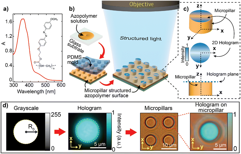
The azopolymer was synthesized via radical polymerization of the photo-responsive monomer (E)-2-(4-((4-methoxyphenyl)diazenyl)phenoxy)ethyl acrylate, according to a previously reported procedure.52 Reagents for the synthesis were purchased from Merck and used without further purification. Fig. 1a shows the chemical structure and the absorption spectrum of the azopolymer used in this work, which is consistent with typical derivatives with symmetric substitution of weak electron-donor alkoxy groups.53–55 Further details of the azopolymer synthesis and characterization (thermal analysis, molecular weight distribution) have been reported in previous works.37,41,42Fabrication of the azopolymer-based micropillar array
The micropillar array on the azopolymer surface was fabricated using soft lithography. First, a soft negative template was fabricated by transferring the intended micropillar array pattern from a silicon master to a polydimethylsiloxane (PDMS) substrate. This process resulted in a PDMS substrate containing the negative pattern of the intended micropillar array. Second, a few drops of a 10 wt% of azopolymer solution in the 1,1,2,2-tetrachloroethane were poured onto a standard glass microscope coverslip as illustrated in Fig. 1b. Afterwards, the PDMS template was laid on the polymer solution, to facilitate its infiltration into the patterned mold. The sample was left at room temperature for 5 h to allow the complete evaporation of the solvent through the PDMS micropores. Finally, the azopolymer film with the desired micropillar array was obtained after carefully peeling the PDMS template from the azopolymer film surface (Fig. 1b). Additional details of the process are provided in previous works.41,42 The micropillars used in this study have a height of Ho ≈ 2.8 μm and a diameter of Do ≈ 7.2 μm in a square lattice with a periodicity of P = 12 μm.Generation of 2D structured intensity patterns of light
This study employed a custom CGH system to generate and project structured grayscale intensity patterns of light on the top surface of the micropillar array. The optical configuration and the algorithms for the hologram design have been extensively described in our previous works.35–37 A λ = 491 nm laser beam (from a Cobolt, Calypso laser) was expanded, collimated, and directed onto a phase-only spatial light modulator (SLM, Holoeye Pluto), where it was modulated with a calculated phase profile (kinoform). The modulated beam from the SLM was propagated through a 4f lenses configuration, designed to produce a demagnified image of the field at the SLM plane in the back focal plane of a microscope objective (Mitutoyo, 50×, NA = 0.55). This configuration allows to project a designed holographic illumination onto the surface of the target micropillars. This light distribution is designed from a bitmap grayscale image (1080 × 1080 pixels), reproducing the target light distribution in the sample plane, was designed with conventional image processing software. To match the diameter of the top surface of the micropillar, each grayscale pattern was designed within a circular area with a diameter of D0 = 2R0 of 19 pixels, which corresponded to approximately 7.4 μm in the holographic pattern. This value was obtained from a conversion factor of 1 pixel ≈ 0.39 μm, previously determined for our experimental setup.36,37 The grayscale image was then used to calculate a set of 1000 independent kinoforms by means of a iterative Fourier transform algorithm,56 based on the mixed region amplitude freedom (MRFA) extension of the standard Gerchberg–Saxton phase-retrieval algorithm.57 To reduce the effect of the speckle noise associated with the hologram reconstruction,35 the independent kinoforms from the calculated set were displayed sequentially on the SLM at a frame rate of 30 Hz. Such time average reduces the roughness of the irradiated azopolymer surface, as demonstrated elsewhere.35–37 In the typical reconfiguration experiments, we used an array of 7 × 7 circular holograms of diameter D0, designed with different geometries and grayscale values in the position corresponding to the 7 × 7 azopolymer micropillars in the surface.Holographic reconfiguration of the azopolymer micropillar array
An imaging system with a camera (DCC3240M from Thorlabs, integrated in the CGH optical system) and a XYZ motorized stage (PI M-111.1DG with C-863 Mercury Servo Controller from Physik Instrumente) are used to visually align and focus the intensity pattern on the prestructured micropillar array to induce local deformations. The holographic beam is circularly polarized, and the typical total power in the sample plane was ≈0.19 mW, distributed over an array of 7 × 7 sub-holograms. The local intensity strongly depends on the actual geometry of each sub-hologram. Different exposure times (in the range of 0–20 s) were used to affect the evolution of the micropillar morphology.Morphological characterization and image of the holographic pattern
Morphological characterization of the microstructures was obtained with an Atomic Force Microscope (AFM, WITec Alpha RS300). Each AFM scan had a resolution of 100 nm and was conducted in tapping mode with high-aspect-ratio probes (ISC-225C3_0-R, from Team Nanotec, aspect ratio >5![[thin space (1/6-em)]](https://www.rsc.org/images/entities/char_2009.gif) :
:![[thin space (1/6-em)]](https://www.rsc.org/images/entities/char_2009.gif) 1, radius <10 nm, half cone angle <5°) mounted on a cantilever with resonance frequency 75 kHz. Quantitative data analysis of the AFM data was performed using Gwyddion58 software. The holographic patterns were obtained by averaging holographic movies taken with the CCD camera.
1, radius <10 nm, half cone angle <5°) mounted on a cantilever with resonance frequency 75 kHz. Quantitative data analysis of the AFM data was performed using Gwyddion58 software. The holographic patterns were obtained by averaging holographic movies taken with the CCD camera.
Results and discussion
Reshaping microstructures with 2D holographic intensity patterns
This study focuses on the 3D reshaping of azopolymer-based micropillars using 2D holographic intensity patterns (hereafter referred to as hologram). The experimental approach is illustrated in Fig. 1b. The pristine array of cylindrical micropillars was replicated on the azopolymer surface by soft molding using a PDMS stamp (see Experimental section). A 2D holographic light pattern generated by CGH was then used to illuminate the micropillars.In our system, the accurate relative positioning of the illumination pattern was achieved by moving the azopolymer films in three dimensions by means of a motorized sample stage. In particular, the sample was translated along the axial direction (z) to make the top surface coincident with the reconstruction plane of the hologram, as schematized in Fig. 1c. In this plane, the intensity gradients in the light pattern have maximum resolution and contrast, resulting in maximized effectiveness of the light-induced reconfiguration process. It should be noted that at the used wavelength, the light penetration depth (∼3.2 μm) is longer than the height of the pristine pillars (∼2.8 μm).41 Moreover, the depth of field (≈λ/NA2) of the microscope objective used to project the holographic pattern is in the same range. This configuration allows for a deformation of a significant fraction of the micropillar volume, where the axial intensity gradient plays a minor role with respect to the transverse gradients in the illumination. In addition, the uniform azopolymer layer left by the soft-molding fabrication process on the bottom of the pillar array (Fig. 1b) is not affected by the light-induced reconfiguration process of the pillar top surface (see also Fig. S1†).
The key element of our technique is the possibility to design a hologram with tailored size with respect to the top surface of the micropillar. To illustrate the general workflow of the method, in the first implementation of this work we designed a circular uniform area with a uniform grayscale level, as presented in Fig. 1d. This grayscale image is then fed into the CGH calculation algorithm, which provides the phase profile used for the hologram reconstruction by means of the SLM (see Experimental section). In a typical reconfiguration experiment, the hologram is then projected in the sample plane and aligned with the top surface of a micropillar with the aid of the brightfield microscope configuration integrated into the holographic system. Fig. 1d shows the intensity pattern of the hologram and the result of the alignment for the homogeneous intensity distribution considered. Importantly, the light distribution and the relative positioning can be easily tuned, as demonstrated in the next sections.
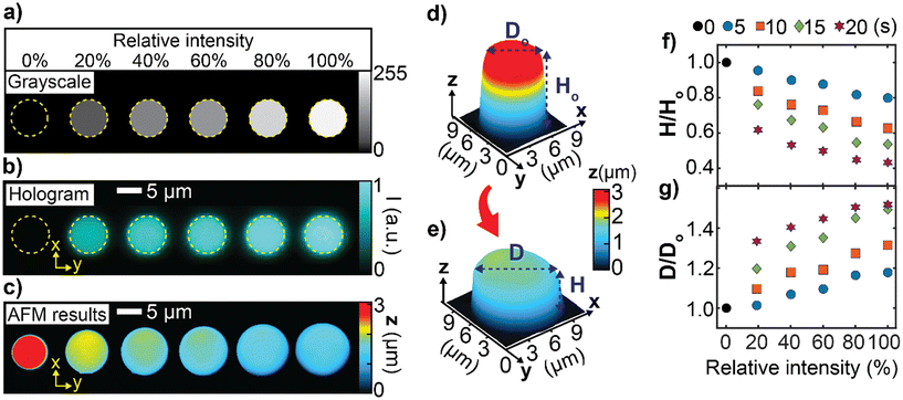
The first demonstration of the capability of our technique is shown in Fig. 2, where we used circular holographic patterns of the same diameter as the top surface of the pristine pillars to selectively reconfigure adjacent micropillars. Fig. 2a displays the hologram design, which consisted of six circles with varying relative grayscale levels. The intensity level in the design was encoded as an 8-bit level in the bitmap image. From this grayscale pattern, six circular holograms with varying relative light intensity levels (0–100%) were generated by the CGH system and used to illuminate a row of six micropillars (Fig. 2b). The result of the light-induced structural reconfiguration of the sub-array after 15 s of exposure is shown in the AFM image in Fig. 2c. The different intensity of the holograms at the same exposure time causes various deformation rates of the micropillars' architecture as shown in Fig. 2c.
To provide closer insight into the reconfiguration process of each individual micropillar of the array, Fig. 2d and e show a 3D morphological comparison of the initial geometry (0% intensity pattern or no illumination) and the one reconfigured by the circular hologram with relative intensity of 60%. The three-dimensional reconfiguration of the micropillar results in a reduction in height and an expansion in diameter with respect to the original geometry. This is a consequence of the approximate preservation of the polymer volume during the light-induced mass migration, accompanied by isotropic pillar elongation in the polarization plane. This mechanism has been successfully modeled in previous theoretical works by assuming a viscoplastic deformation of the polymer, driven by a light-induced stress.19–21 In addition, same behavior has been observed when the entire pillar array is irradiated with an extended homogeneous, circularly polarized beam, as demonstrated in previous works.41,42
The degree of the deformation depends on the exposure dose, which can be tuned by controlling either the light intensity level or the exposure time. In single-beam experiments, only one of the two parameters is typically varied,42,44,45,47 producing a controlled reconfiguration of the microstructures in the illuminated area, but without any local spatial selectivity. Fig. 2c highlights the peculiarity of our holographic scheme, which overcomes this limitation by allowing spatially selective tuning of the exposure dose. The linear increase of the relative intensity level in the hologram (Fig. 2a and b) results in an almost linear decrease of the height and an increase of the diameter of the illuminated pillars of the same array. Notably, the exposure time can also be varied, providing spatially selective control over the exposure dose and the reconfiguration dynamics of azopolymer microstructures (Fig. 2f and g).
It is worth noting that in the configuration shown in Fig. 2b, the circular uniform hologram had the same diameter as the top surface of the pillar to uniformly reshape the top perimeter of each pillar in the array. This is accomplished by designing the hologram to have approximately the same radius R0 as the pillar. However, the full potential of our technique is demonstrated when a spatially structured intensity distribution, with eventual directional gradients, is irradiated over an area smaller than the pillar diameter (R < R0). In our holographic system, these light patterns can be systematically tuned by designing a spatial variation of the gray levels in the bitmap image used for the hologram design.
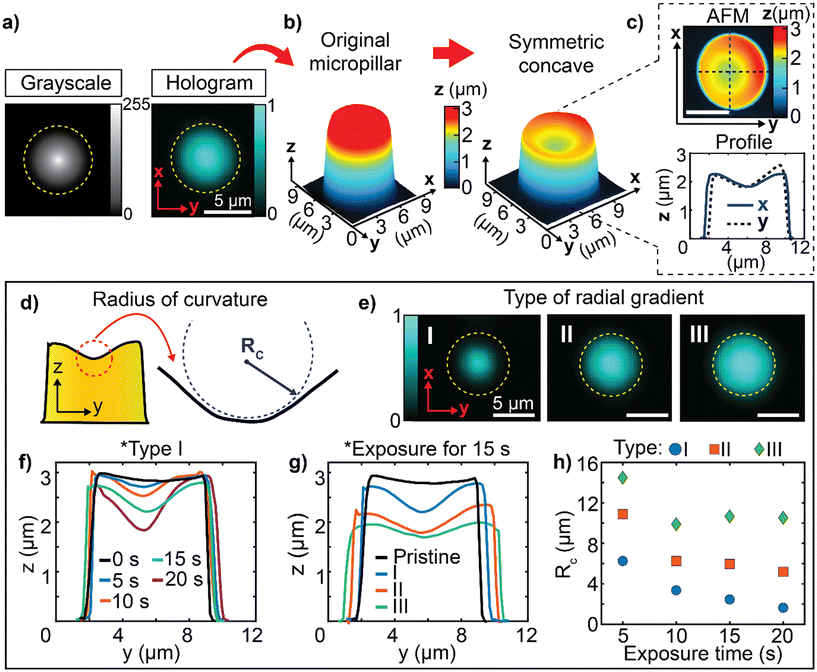
Fig. 3a presents the exemplifying situation of a simple radial intensity gradient (going from 100% to 0% relative intensity) that is developed from the center of the pillar to a radius equal to 0.8R0. The experimental hologram produced by the CGH system using this grayscale design follows the same radial gradient, as shown in the image in Fig. 3a (right). When aligned with the center of an azopolymer micropillar, the intensity distribution of the radial hologram produces a concave deformation in the pillar center with radial symmetry (Fig. 3b). The top view of the AFM scan and the topographic profile show the detail of the reshaped pillar (Fig. 3c).
To describe the relationship between the spatial intensity gradient and the final morphology of the microstructures, we measured the radius of curvature (Rc) of the surface of the concave reshaped pillar, as illustrated in Fig. 3d. Exposure time and extension (and hence local strength) of the intensity gradient were varied in the analysis. In particular, we designed three radially symmetric linear gradients of radius 0.5R0, 0.8R0 and R0, producing the holographic patterns of type I, II, and III in Fig. 3e, respectively.
Fig. 3f shows the topographic profiles of the pillars irradiated with the pattern type I for different exposure times. The curvature of the surface becomes more pronounced as the exposure time increases. This is described by the decrease in Rc as a function of exposure time shown in Fig. 3h. Variations in the extension of the intensity gradient for the same exposure time result in smaller curvatures, as demonstrated by the evolution of the topographic profiles in Fig. 3g and the measured radius of curvature in Fig. 3h.
This behavior highlights one of the general features of the light-induced mass migration of the azopolymer in the presence of intensity gradients of circularly polarized light. The motion of the material in such an illumination configuration is driven isotropically along the direction of the gradient with a strength determined by the local intensity gradient, which is higher for type I holograms than for type II and III (Fig. 3e). As a result, type I hologram produces the larger deformation of the top surface of the pillar, with the smaller radius of curvature. A longer exposure time results in a higher accumulation of this mass migration effect, thereby increasing the total deformation of the top surface, but with higher deformation rates for stronger intensity gradients (Fig. 3h).
Reconfiguring microstructures with morphological complexity
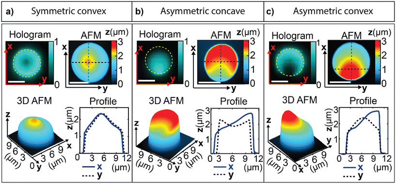
To further demonstrate the flexibility of this technique, several unique microstructural morphologies were created by projecting different holograms with deterministically designed spatial intensity patterns on the array of the pristine azopolymer micropillars.We first demonstrated the ability to invert the geometry of the reshaped micropillar by reversing the direction of the intensity gradient in the holograms. As an example, Fig. 4a shows a radial gradient pattern designed as the complimentary of the pattern in Fig. 3a, resulting in a hologram with the minimum light intensity in the center. This pattern produces a symmetric convex surface profile in the final morphology, which is the inverse of the concave profile demonstrated above.
Further more complex light-induced structural transformations derive from shifting the center of the gradient in the hologram to produce asymmetric three-dimensional architectures. Fig. 4b shows a petal-like hologram designed with the center at the perimeter of the pillar. Such a design is associated with an asymmetric intensity gradient across the top surface of the pillar, which ultimately creates an asymmetric concave reconfigured microstructure. The result is a slanted profile along the x-axis and a concave profile along the y-axis, as shown in Fig. 4b. Similar to the previous case, the microstructure endowed with the inverse of this morphology can be obtained by reversing the direction of the intensity gradient in the petal-like hologram (Fig. 4c). In this case, an asymmetric convex structure is obtained after the light-induced reconfiguration process of the pristine micropillar.
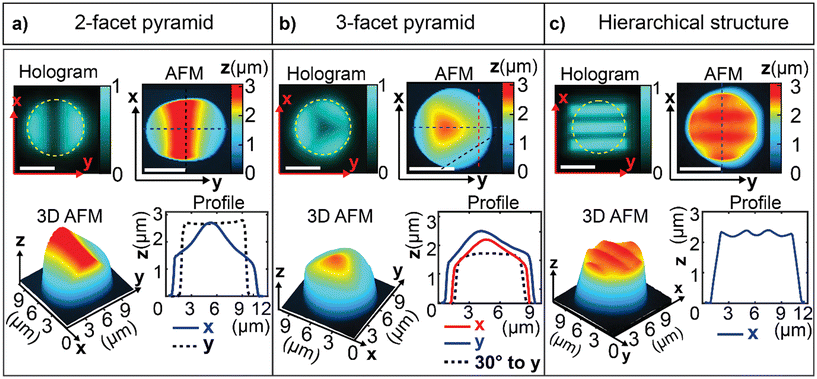
Such approach allows to mold azopolymer micropillars with multifaceted designs, as shown in Fig. 5a and b. Each facet is a unidirectional intensity gradient that evolves from the minimum intensity at the center of the circle to the maximum intensity at the perimeter of the circle. This design enables the creation of multiple slanted facets, such as the 2-facet micro-pyramid shown in Fig. 5a and the 3-facet micro-pyramid shown in Fig. 5b.
The hologram design could be extended to more complex patterns, further widening the range of achievable geometric diversity for the reconfigured microstructures. To highlight this capability, Fig. 5c shows an example of a hierarchical grating-like texture produced on the top of the micropillar surface by a multi-line hologram. Even if the illumination pattern is designed with a lateral size larger than the micropillar diameter, the bottom layer is not affected due to the limited depth of field of the projection system (see also Fig. S1 in the ESI†). This mitigates the effects of imperfect alignment between the holographic illumination and the pre-structured surface. More complex patterns are possible by exploiting the flexibility of our CGH system.35–37 The ultimate limit is dictated by the spatial resolution and the gradient strength achievable in the hologram, which are mainly determined by the characteristics of the SLM, such as the number of pixels, the pixel size, and the size of the modulating display.
Group-selective reconfiguration capability
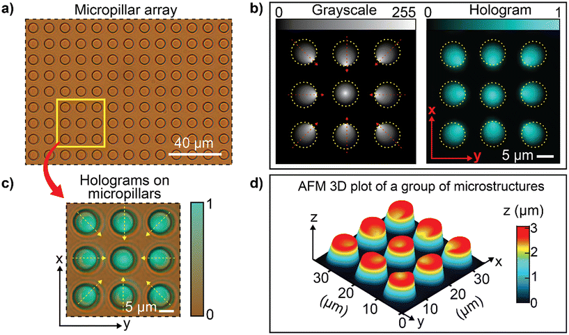
It is worth mentioning that our holographic configuration allows all types of light-induced reconfigurations presented to be performed simultaneously for each micropillar entering in the field of view (FoV) of the optical system used (diameter of ∼200 μm in our setup) with a single exposure. The pillars within the FoV can be individually reconfigured by an independent portion of an extended hologram, designed with a desired distribution of light gradients. This capability enables the deterministic reshaping of a group of micropillars with individual structural diversity (see also Fig. S2 in the ESI†).Fig. 6a shows a brightfield microscope image of a region of the original micropillar array. A group of micropillars can be arbitrarily selected in any region of interest. A group of nine neighboring micropillars, highlighted by the yellow box in Fig. 6a, has been selected here for demonstration. A hologram consisting of nine patterns with different intensity gradients was designed to match the position of the micropillars (Fig. 6b) and was projected onto the selected azopolymer sub-array (Fig. 6c).
The three-dimensional AFM image in Fig. 6d shows the reconfigured microstructures after the holographic irradiation. According to the design, the final microstructures in the group consist of eight slanted concave microstructures with surfaces tilted towards different relative directions and one symmetrical concave microstructure in the center.
In addition to the limited range of achievable geometries, a similar simultaneous group-selective structural diversity on azopolymer microstructures is not accessible with any other optical configuration reported to date, including homogeneous single-beam, multistep/multi-beam exposure, and scan-based spot illumination.41,42,46,49,50,59 It should be noted that the selective control offered by our holographic reconfiguration could be directly extended to larger areas (beyond the diameter of ∼200 μm of our current configuration) by using higher numerical aperture and lower magnification objectives, coupled with high-resolution SLMs. By tiling and stitching the surface using motorized stages, even larger areas in the range of cm2 can be reached, opening to exploitation of the tailored surfaces for macroscopic applications.
Conclusions
In this work, we have successfully demonstrated the molding of microstructures with holographically structured spatial distributions of light intensity. Depending on the exposure dose and the intensity gradient of the light across the top surface of an azopolymer micropillar, the reshaped microstructure geometry can be tuned in three dimensions. Using this mechanism, we have transformed micropillars of a single pristine array into various microstructures showing concave, convex, slanted, multifaceted, and hierarchical morphologies. Although in this study we have demonstrated multiple architectures, our technique offers an even broader range of possible morphologies. Indeed, the process of reshaping using holographic patterns is dependent on the geometric parameters of the original azopolymer microstructure, such as its shape, height, and width, as well as the grayscale patterns, light intensity, and CGH configuration, each being a further tunable parameter. We also demonstrated the group-selective capability of our technique by modifying a sub-array of micropillars into asymmetric microstructures with different relative orientations in one single exposure. This ability could be coupled with the sample translation to cover a larger area, while maintaining the full control over the individual microstructure reconfiguration. Future applications of our technique can range from the fabrication of diffractive surfaces for photonics to the engineering of patterned substrates able to tune physical properties such as wettability and adhesion, where control over the morphology of the microstructure array is required.Data availability statement
Data underlying the results presented in this paper are not publicly available at this time but may be obtained from the authors upon reasonable request.Author contributions
Conceptualization: S. L. O.; methodology: S. L. O. and I K. J.; funding acquisition: S. L. O. and M. S.; investigation and data curation: I K. J., F. B., F. R., and M. S.; validation: S. L. O., M. S.; visualization: I K. J. and F. R.; supervision: S. L. O.; project administration: S. L. O. Writing – original draft: I K. J. and F. R. with contributions of all authors; writing – review & editing: S. L. O., I K. J, F. R. All authors have given approval to the final version of the manuscript.Conflicts of interest
There are no conflicts to declare.Acknowledgements
This work has been financially supported by the Italian Ministry of University and Research through Piano Nazionale di Ripresa e Resilienza (PNRR) - Missione 4, Componente 2, investimento 1.1, PRIN PNRR 2022 program (Grant no. P2022FKL2M) and by University of Naples Federico II through FRA 2023 program (project “Holographic Surface Photopatterning for Information Encryption”).Notes and references
- L. Jia, J. Jiang, T. Xiang and S. Zhou, Adv. Mater. Interfaces, 2022, 9, 2201270 CrossRef CAS.
- M. Schumann, T. Bückmann, N. Gruhler, M. Wegener and W. Pernice, Light: Sci. Appl., 2014, 3, e175 CrossRef CAS.
- Q. Zhang, Z. He, Z. Xie, Q. Tan, Y. Sheng, G. Jin, L. Cao and X. Yuan, Photonics Insights, 2023, 2, R09 CrossRef.
- S. Nocentini, D. Martella, C. Parmeggiani and D. S. Wiersma, Adv. Opt. Mater., 2019, 7, 1900156 CrossRef.
- S. Wooh, H. Yoon, J. Jung, Y. Lee, J. H. Koh, B. Lee, Y. S. Kang and K. Char, Adv. Mater., 2013, 25, 3111–3116 CrossRef CAS PubMed.
- Y. Jung, J. Ahn, J. Kim, J. Ha, J. Shim, H. Cho, Y. S. Oh, Y. Yoon, Y. Nam, I. Oh, J. Jeong and I. Park, Small Methods, 2022, 6, 2200248 CrossRef CAS PubMed.
- M. Liu, S. Wang and L. Jiang, Nat. Rev. Mater., 2017, 2, 17036 CrossRef CAS.
- Z. Cheng, D. Zhang, X. Luo, H. Lai, Y. Liu and L. Jiang, Adv. Mater., 2021, 33, 2001718 CrossRef CAS PubMed.
- M. Kang, J. H. Byun, S. Na and N. L. Jeon, RSC Adv., 2017, 7, 13353–13361 RSC.
- J. Zhai, H. Li, A. H.-H. Wong, C. Dong, S. Yi, Y. Jia, P.-I. Mak, C.-X. Deng and R. P. Martins, Microsyst. Nanoeng., 2020, 6, 6 CrossRef CAS PubMed.
- J. Qin, L. Yin, Y. Hao, S. Zhong, D. Zhang, K. Bi, Y. Zhang, Y. Zhao and Z. Dang, Adv. Mater., 2021, 33, 2008267 CrossRef CAS PubMed.
- F. He, X. You, W. Wang, T. Bai, G. Xue and M. Ye, Small Methods, 2021, 5, 2001041 CrossRef CAS PubMed.
- K. Chen, Z. Guan, Z. Li, Y. Yang, Z. He, S. Yu and G. Zheng, Laser Photonics Rev., 2023, 17, 2200448 CrossRef.
- M. Zhang, A. Pal, X. Lyu, Y. Wu and M. Sitti, Nat. Mater., 2024, 23, 560–569 CrossRef CAS PubMed.
- P. van Assenbergh, E. Meinders, J. Geraedts and D. Dodou, Small, 2018, 14, 1703401 CrossRef PubMed.
- J. Del Barrio and C. Sánchez-Somolinos, Adv. Opt. Mater., 2019, 7, 1900598 CrossRef.
- S. L. Oscurato, M. Salvatore, P. Maddalena and A. Ambrosio, Nanophotonics, 2018, 7, 1387–1422 CrossRef CAS.
- A. Priimagi and A. Shevchenko, J. Polym. Sci., Part B: Polym. Phys., 2014, 52, 163–182 CrossRef CAS.
- N. Tverdokhleb, S. Loebner, B. Yadav, S. Santer and M. Saphiannikova, Polymers, 2023, 15, 463 CrossRef CAS PubMed.
- S. Loebner, B. Yadav, N. Lomadze, N. Tverdokhleb, H. Donner, M. Saphiannikova and S. Santer, Macromol. Mater. Eng., 2022, 307, 2100990 CrossRef CAS.
- B. Yadav, J. Domurath, K. Kim, S. Lee and M. Saphiannikova, J. Phys. Chem. B, 2019, 123, 3337–3347 CrossRef CAS PubMed.
- M. Saphiannikova, V. Toshchevikov and N. Tverdokhleb, Soft Matter, 2024, 20, 2688–2710 RSC.
- F. Reda, M. Salvatore, F. Borbone, P. Maddalena and S. L. Oscurato, ACS Mater. Lett., 2022, 4, 953–959 CrossRef CAS.
- M. Salvatore, F. Reda, F. Borbone, I. K. Januariyasa, P. Maddalena and S. L. Oscurato, Polymers, 2023, 15, 1605 CrossRef CAS PubMed.
- Y. Lim, B. Kang, S. J. Hong, H. Son, E. Im, J. Bang and S. Lee, Adv. Funct. Mater., 2021, 31, 2104105 CrossRef CAS.
- O. Sakhno, L. M. Goldenberg, M. Wegener, C. Dreyer, A. Berdin and J. Stumpe, Opt. Mater., 2022, 128, 112457 CrossRef CAS.
- A. Kozanecka-Szmigiel, A. Hernik, K. Rutkowska, J. Konieczkowska, E. Schab-Balcerzak and D. Szmigiel, Materials, 2022, 15, 8088 CrossRef CAS PubMed.
- J. Jelken, C. Henkel and S. Santer, Appl. Phys. B: Lasers Opt., 2020, 126, 149 CrossRef CAS.
- A. Berdin, H. T. Rekola and A. Priimagi, Adv. Opt. Mater., 2024, 12, 2301597 CrossRef CAS.
- S. L. Oscurato, F. Reda, M. Salvatore, F. Borbone, P. Maddalena and A. Ambrosio, Adv. Mater. Interfaces, 2021, 8, 2101375 CrossRef CAS.
- Y. Lim, B. Kang and S. Lee, Adv. Funct. Mater., 2021, 31, 2100839 CrossRef CAS.
- M. Salvatore, F. Borbone and S. L. Oscurato, Adv. Mater. Interfaces, 2020, 7, 1902118 CrossRef CAS.
- H. Rekola, A. Berdin, C. Fedele, M. Virkki and A. Priimagi, Sci. Rep., 2020, 10, 19642 CrossRef CAS PubMed.
- J. Strobelt, M. Van Soelen, H. Abourahma and D. J. McGee, Adv. Opt. Mater., 2023, 11, 2202245 CrossRef CAS.
- S. L. Oscurato, M. Salvatore, F. Borbone, P. Maddalena and A. Ambrosio, Sci. Rep., 2019, 9, 6775 CrossRef PubMed.
- S. L. Oscurato, F. Reda, M. Salvatore, F. Borbone, P. Maddalena and A. Ambrosio, Laser Photonics Rev., 2022, 16, 2100514 CrossRef.
- F. Reda, M. Salvatore, M. Astarita, F. Borbone and S. L. Oscurato, Adv. Opt. Mater., 2023, 11, 2300823 CrossRef CAS.
- J. Strobelt, D. Stolz, M. Leven, M. V. Soelen, L. Kurlandski, H. Abourahma and D. J. McGee, Opt. Express, 2022, 30, 7308 CrossRef CAS PubMed.
- F. Reda, M. Salvatore, F. Borbone, P. Maddalena, A. Ambrosio and S. L. Oscurato, Opt. Express, 2022, 30, 12695 CrossRef CAS PubMed.
- O. Senel, B. Gruppuso, J. Strobelt and D. J. McGee, in Advanced Fabrication Technologies for Micro/Nano Optics and Photonics XVII, ed. G. Von Freymann, E. Blasco and D. Chanda, SPIE, San Francisco, United States, 2024, p. 33 Search PubMed.
- I. K. Januariyasa, F. Borbone, M. Salvatore and S. L. Oscurato, ACS Appl. Mater. Interfaces, 2023, 15, 43183–43192 CrossRef CAS PubMed.
- S. L. Oscurato, F. Borbone, P. Maddalena and A. Ambrosio, ACS Appl. Mater. Interfaces, 2017, 9, 30133–30142 CrossRef CAS PubMed.
- J. Choi, W. Jo, S. Y. Lee, Y. S. Jung, S.-H. Kim and H.-T. Kim, ACS Nano, 2017, 11, 7821–7828 CrossRef CAS PubMed.
- X. Kong, X. Wang, T. Luo, Y. Yao, L. Li and S. Lin, ACS Appl. Mater. Interfaces, 2017, 9, 19345–19353 CrossRef CAS PubMed.
- Z. Wang, H. Huang, C. Hsu and X. Wang, Adv. Opt. Mater., 2022, 10, 2102795 CrossRef CAS.
- S. Lee, H. S. Kang, A. Ambrosio, J.-K. Park and L. Marrucci, ACS Appl. Mater. Interfaces, 2015, 7, 8209–8217 CrossRef CAS PubMed.
- M. Salvatore, F. Borbone, F. Reda, P. Maddalena and S. L. Oscurato, JPhys Photonics, 2021, 3, 034013 CrossRef CAS.
- Z. Wang, C. Hsu and X. Wang, Sci. Rep., 2021, 11, 7327 CrossRef CAS PubMed.
- W. Jo, H. S. Kang, J. Choi, J. Jung, J. Hyun, J. Kwon, I. Kim, H. Lee and H.-T. Kim, Nano Lett., 2021, 21, 5500–5507 CrossRef CAS PubMed.
- H. S. Kang, J. C. Jolly, H. Cho, A. Kalpattu, X. A. Zhang and S. Yang, Adv. Mater., 2021, 33, 2005454 CrossRef CAS PubMed.
- K. Matsushima, Introduction to Computer Holography: Creating Computer-Generated Holograms as the Ultimate 3D Image, Springer International Publishing, Cham, 2020 Search PubMed.
- F. Borbone, S. L. Oscurato, S. Del Sorbo, F. Pota, M. Salvatore, F. Reda, P. Maddalena, R. Centore and A. Ambrosio, J. Mater. Chem. C, 2021, 9, 11368–11375 RSC.
- H. M. D. Bandara and S. C. Burdette, Chem. Soc. Rev., 2012, 41, 1809–1825 RSC.
- M. Gao, D. Kwaria, Y. Norikane and Y. Yue, Natural Sciences, 2023, 3, e220020 CrossRef CAS.
- J. Garcia-Amorós, M. Martínez, H. Finkelmann and D. Velasco, J. Phys. Chem. B, 2010, 114, 1287–1293 CrossRef PubMed.
- M. Pasienski and B. DeMarco, Opt. Express, 2008, 16, 2176 CrossRef PubMed.
- R. W. Gerchberg and W. O. Saxton, Optik, 1972, 35, 237–246 Search PubMed.
- D. Nečas and P. Klapetek, Gwyddion (version 2.62), Czech Metrology Institute, 2022 Search PubMed.
- F. Pirani, A. Angelini, F. Frascella, R. Rizzo, S. Ricciardi and E. Descrovi, Sci. Rep., 2016, 6, 31702 CrossRef CAS PubMed.
Footnote |
| † Electronic supplementary information (ESI) available. See DOI: https://doi.org/10.1039/d4lf00092g |
| This journal is © The Royal Society of Chemistry 2024 |

