
Fabrication of sac-like hydrogel membranes for replicating curved tissue barriers on chips†
Wenqi
She
a,
Chong
Shen
a,
Yinghua
Ying
b and
Qin
Meng
 *a
*a
aKey Laboratory of Biomass Chemical Engineering (Education Ministry), College of Chemical and Biological Engineering, Zhejiang University, 38 Zheda Road, Hangzhou, Zhejiang 310027, China. E-mail: mengq@zju.edu.cn
bKey Laboratory of Respiratory Disease of Zhejiang Province, Department of Respiratory and Critical Care Medicine, Second Affiliated Hospital of Zhejiang University School of Medicine, Hangzhou, Zhejiang 310009, China
First published on 20th November 2023
Abstract
Current organ-on-a-chip (OOC) systems cannot mimic in vivo tissue barriers that feature curved geometries and rhythmic movement. This is due to the lack of a relevant membrane that can reproduce the natural biochemical and physical properties of a basement membrane, especially the characteristic sac-like structure possessed by multiple tissue barriers. To address this challenge, a sac-like hydrogel membrane is fabricated here using a one-step simple methodology inspired by soap bubble formation. Di-acrylated Pluronic® F127 (F127-DA) is a hydrogel that exhibits excellent mechanical properties, stably withstanding rhythmic mechanical stretching and fluid flow for at least 24 h. Using this hydrogel to make a membrane, a complex lung-on-a-chip device is successfully constructed, effectively replicating the alveolar-capillary barrier and demonstrating cellular function under physiological respiratory conditions. This membrane offers a crucial platform for replicating sac-like tissue barriers.
1. Introduction
Organ-on-a-chip (OOC) devices are capable of recreating the functional units of living organs using microfluidics, and are thus being developed into powerful preclinical models.1 In such three-dimensional (3D) OOC devices, chemical components, spatial structures, mechanical cues, and multicellular interactions can be precisely engineered to mimic in vivo microenvironments.2 Thus, OOC devices have the unique capability to replicate complex tissue–tissue interfaces, in particular, important human tissue barriers.3Typically, a thin, planar, and unidirectionally stretchable synthetic polymeric membrane, made from polydimethylsiloxane (PDMS), has been used as the substrate membrane in the construction of classical OOC devices, with cells individually cultivated on the top/bottom side to reproduce the tissue barrier.4–6 Such membranes are generally hydrophobic and exhibit low pre-cellular adhesion as well as cell migration. Moreover, the high membrane stiffness severely impairs late cellular differentiation, failing to fully replicate the extracellular matrix (ECM) in vivo.4–10 Therefore, replacing polymeric membranes with biomaterials with ECM properties would offer great potential for constructing tissue barriers with higher fidelity.
Soft and wet hydrogels have been recognized as the preferred choice for organoids and OOC systems due to their high biocompatibility and tunable properties (e.g., stiffness, permeability, and elasticity).11 The cell–cell and cell–ECM exchange of nutrients, oxygen, cell factors, and metabolic waste can be readily simulated in porous hydrogels with no need for extra mechanical perforation. This is crucial for maintaining cell osmotic pressure and normal functionality in multi-layer cell cultures.12 More importantly, hydrogels are anticipated to mimic the native ECM by modulating their desirable biochemical and physical properties, which in turn can modulate cell behavior and tissue function.13,14
However, the hydrogel membranes mentioned above generally form as 2D flat plates. This flatness means that the membranes deviate greatly from the physiological anatomy and structure of in vivo complex barrier tissues with 3D geometries.15 The surface curvature of the tissue microenvironment is known to influence cell alignment, polarity, and migration.16,17 Hence, it remains a challenge to replicate complex tissue–tissue interfaces with curved geometries, such as the alveolar-capillary barrier (Fig. 1A),10,18 corneal barrier (Fig. 1Bi),19,20 blood–retinal barrier (Fig. 1Bii),21,22 glomerular filtration barrier (Fig. 1C),23,24 and glandular vesicles barriers (Fig. 1D).
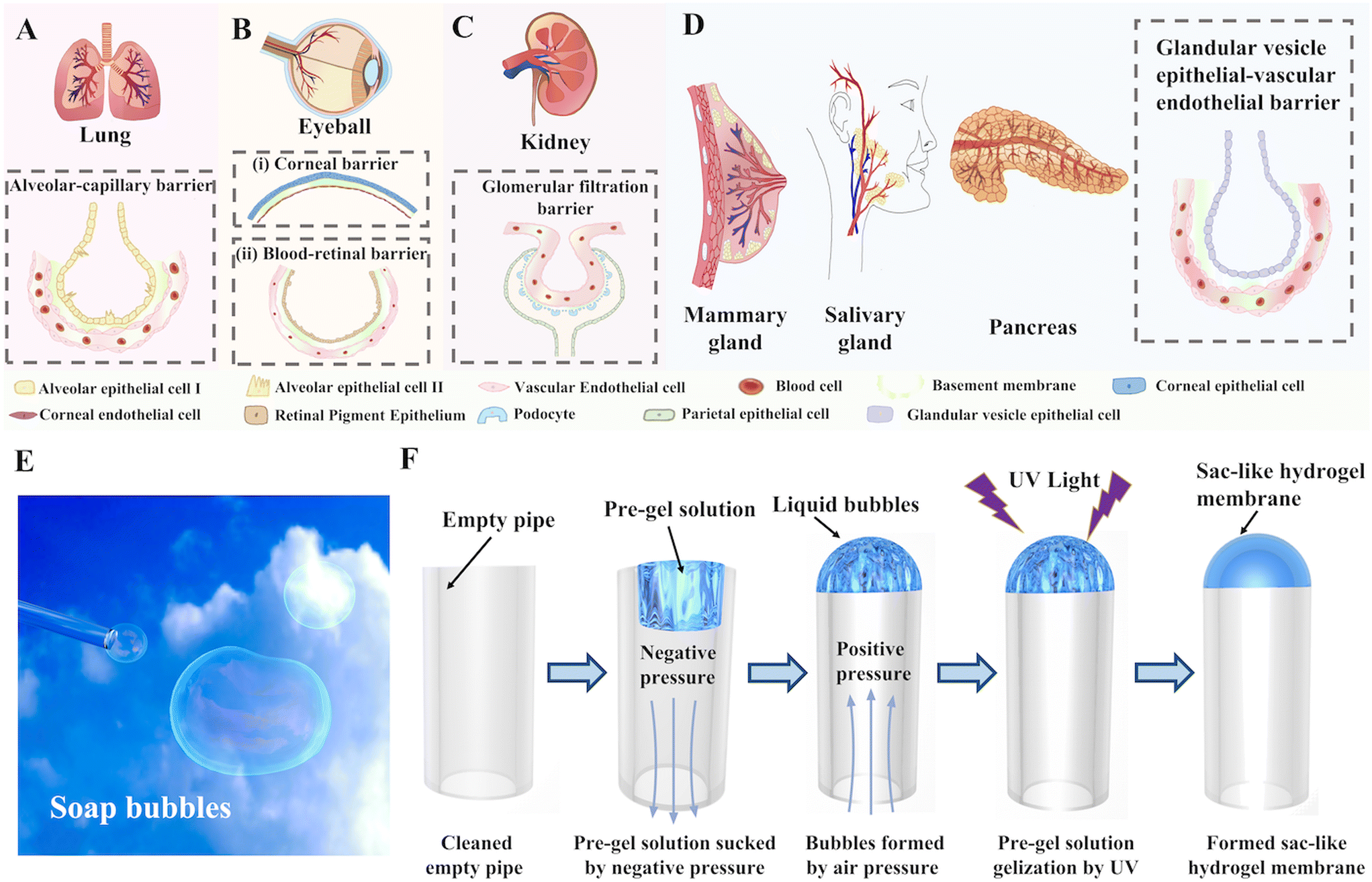 | ||
| Fig. 1 The surface curvatures of tissue microenvironments and the relevant simulation using sac-like hydrogel membranes inspired by soap bubble formation. A) Alveolar-capillary barrier in the lung. B) Corneal barrier (i) and blood–retinal barrier (ii) in the eyeball. C) Glomerular filtration barrier in the kidney. D) Glandular vesicle epithelial–vascular endothelial barrier in the mammary gland, salivary gland, and pancreas. E) Soap bubble formation. F) Schematic diagram of the fabrication of the sac-like hydrogel membranes. | ||
In this study, we report the first generation of sac-like hydrogel membranes with surface curvature for the construction of tissue barriers in OOC systems, as inspired by the formation of soap bubbles (Fig. 1E). The hydrogel solution, in a manner similar to a soap solution, formed bubbles when placed under a pressurized airflow before being quickly cured under UV light (Fig. 1F). This template-free methodology is applicable to a wide range of common photoinitiated hydrogels and pipelines, providing simplicity, efficiency, and scalability for the large-scale production of sac-like hydrogel membranes. Utilizing the individual confluent growth of human pulmonary alveolar epithelial cells (HPAEpiCs) and human umbilical vein endothelial cells (HUVECs) on the inner and outer sides of the hydrogel membrane, an alveolar-capillary barrier was established and could work under physiological fluid flow and respiratory strain. Such a 3D hydrogel membrane with a complex conformation will open up new pathways for biomimetically constructing OOC devices with highly complex biological barrier systems, particularly useful for lung-on-a-chip systems.
2. Material and methods
2.1. Materials
Pluronic® F127 (EO98PO69EO98) and gelatin from porcine skin were obtained from Sigma-Aldrich (USA). Methacrylated gelatin (Gel-MA) was synthesized following our previously reported method.25 Irgacure 2959 and benzophenone (BP) were acquired from BASF (USA). A Sylgard 184 silicone elastomer kit (PDMS) was purchased from Corning Incorporated (USA). HPAEpiCs and HUVECs were obtained from Guandao Co. (China). Sulfo-SANPAH, fetal bovine serum (FBS), dimethyl sulfoxide (DMSO), phosphate buffered saline (PBS), Dulbecco's modified Eagle's medium (DMEM), Ham's F12 nutrient medium, FITC-dextran (70 kDa) and antibiotic (penicillin–streptomycin) were ordered from Fisher Scientific (USA). Rat tail collagen I (Col-I) was obtained from Shengyou Biological Technology Co., Ltd. (China). Calcein-AM, propidium iodide (PI), anti-epithelial growth factor receptor protein (EGFR), anti-surfactant associated protein C (SPC), anti-vimentin, anti-vascular endothelial growth factor (VEGF), anti-E-cadherin, anti-TJP1, goat anti-rabbit IgG secondary antibody, FITC-phalloidin, and 4′,6-diamidino-2-phenylindole (DAPI)-staining-solution were purchased from Boster Bio. Co., Ltd. (China). The ELISA quantification kit of human Col-I, collagen IV (Col-IV), endothelin-1 (ET-1), intercellular adhesion molecule 1 (ICAM-1), and nitric oxide (NO) were acquired from Yuannuo Technology Co., Ltd. (China). All other chemicals and reagents used in this study were of analytical grade and were obtained from Sinopharm Chemical Reagent Co., Ltd. (China).2.2. Synthesis of di-acrylated Pluronic® F127 (F127-DA)
F127-DA was synthesized following our previously reported method.25 Briefly, 26 g of PF127 and 100 mL of tetrahydrofuran (THF) were mixed well in a round-bottomed flask and heated at 40 °C. Then, the reaction solution was subjected to condensation by adding 3840 mL of triethylamine. Meanwhile, 30 mL of THF and 3520 mL of acryloyl chloride were mixed and dropped into the reaction solution in an ice-water bath. After a 24 h reaction, the solution was centrifuged to separate the supernatant. The supernatant was then subjected to spin evaporation to obtain the product, which was washed with anhydrous ether. The dry crude product was then dissolved in deionized water, dialyzed using a dialysis membrane (3.5 kDa) for 3 days, and freeze-dried to obtain pure F127-DA.2.3. Fabrication of the sac-like hydrogel membrane
The PU pipes (OD = 1 mm, ID = 0.7 mm) were firstly cleaned with ethanol and subsequently immersed in an acetone solution of BP (10 wt%) for 10 min before being cleaned with ethanol and dried with nitrogen. Then, 0.17 μL of pre-gel solution (15 wt% F127-DA with 0.5 wt% Irgacure I-2959 in water) was taken and dropped into the tip of the pipe using a syringe pump (RISTRON RSP02-B, China). This pre-gel solution was pushed up by the air pressure and reached force equilibrium with a semi-spherical shape by using careful pressure adjustments. It was then immediately gelatinized under the irradiation of UV light (LIBI UV-400, λ = 365 nm, China) for 20 s. To create the sac-like hydrogel membranes using other sizes of pipes, the same steps were followed. The volume (V) of the pre-gel solution was calculated using eqn (1): | (1) |
2.4. Measurement of hydrogel membrane thickness
The thickness of the membrane was measured with an IX71 inverted microscope (Olympus, Japan). Briefly, the hydrogel membrane was cut along the radial direction and then attached to the slide. Subsequently, ten points were aliquoted along the radial direction, and the thickness was measured using a scale.2.5. Modification of the F127-DA hydrogel membrane
The gelatinized hydrogel membranes were washed twice with 50 mM HEPES and then immersed in a 50 mg mL−1 sulfo-SANPA solution, followed by exposure to UV light for 20 min. The modified membranes were washed sufficiently with PBS and later incubated in 0.2 mg mL−1 of rat tail Col I solution at 4 °C overnight.2.6. Contact angle measurement
The hydrogels were immersed in PBS solution for 24 h and excess water on the surface was removed with absorbent paper before testing. Subsequently, they were placed on the fixed base of a POWEREACH JC2000P apparatus (China). PBS droplets were dispensed carefully onto the surface of the hydrogel and the shape of the droplets at the contact point was recorded using an optical system equipped with a digital camera. The captured images were then analyzed to determine the contact angle.2.7. Porosity measurement
The porosity was measured using a solvent replacement method.26 The freeze-dried hydrogels were weighed (M1) and then immersed in anhydrous ethanol for 24 h. After removing excess ethanol on the surface, masses and volumes of hydrogels were measured (M2, V). The porosity was calculated according to eqn (2) | (2) |
2.8. Bursting strength measurement
The prepared hydrogel membranes were connected to the syringe through the supporting pipe. The syringe was then pushed at a rate of 20 μL s−1 to stretch the hydrogel until it ruptured. The bursting strength was obtained from eqn (3): | (3) |
2.9. Micro-device design and construction
The microfluidic chip consisted of three layers, with the first layer forming the air chamber and the second and third layers forming the liquid chamber (Fig. S1A†). Micro-patterns were designed using CAD software (SolidWorks, Dassault Systems, USA) and fabricated in white resin by Dmbarley 3D Co., Ltd. (China). To obtain the corresponding PDMS units, PDMS was cast on the white resin masks and cured at 80 °C for 3 h. The second and third PDMS layers were subsequently coated with a thin layer of uncured PDMS on the contact surface and incubated at 80 °C for 2 h to derive the liquid chamber. The obtained liquid and air chambers were wiped with 75% ethanol and irradiated with UV light for sterilization, then assembled with the hydrogel membrane with cells to construct the lung-on-a-chip device. For an adequate seal, the chip was secured using two polymethylmethacrylate (PMMA) slices and four screws to provide an adequate seal (Fig. S1B†).2.10. Computational fluid dynamics (CFD) simulation
The liquid chamber flow fields at various linear strains (0%, 5%, 10%, 15%, and 20%) were modeled using SolidWorks, and the physical model was subsequently meshed and optimized using the CFD software (Fluent, USA). By changing the inlet flow rate, the corresponding flow rate in the liquid chamber and wall shear of the hydrogel membrane were simulated and visualized with cloud diagrams. The simulation was conducted at environmental parameters of T = 37 °C, ρ = 1000 kg m−3, and μ = 0.001 Pa s−1.2.11. Cell culture inside the lung-on-a-chip device
HAPEpiCs and HUVECs were cultured in F12![[thin space (1/6-em)]](https://www.rsc.org/images/entities/char_2009.gif) :DMEM (2:1) medium supplemented with 10% FBS, 0.5% L-glutamine, 100 U mL−1 penicillin, and 100 mg mL−1 streptomycin at 37 °C and 5% CO2, and the medium was changed every 2 days. The cells were harvested at passages 3–6 and adjusted to 1–5 × 10⁶ cells per mL for seeding on the surface of the hydrogel membrane. As shown in Fig. S2,† the HAPEpiCs were injected into the pipes with a syringe and placed vertically for 20 min. Then, the pipes were connected to an interval-subdivided step motor and rotated axially at a constant rate of 0.56 rph for 4 h. Hydrogel membranes seeded with HPAEpiCs were cultured for 36 h after completion of the rotation, then flipped and seeded with HUVECs in the upper PDMS chamber of the cell scaffold.
:DMEM (2:1) medium supplemented with 10% FBS, 0.5% L-glutamine, 100 U mL−1 penicillin, and 100 mg mL−1 streptomycin at 37 °C and 5% CO2, and the medium was changed every 2 days. The cells were harvested at passages 3–6 and adjusted to 1–5 × 10⁶ cells per mL for seeding on the surface of the hydrogel membrane. As shown in Fig. S2,† the HAPEpiCs were injected into the pipes with a syringe and placed vertically for 20 min. Then, the pipes were connected to an interval-subdivided step motor and rotated axially at a constant rate of 0.56 rph for 4 h. Hydrogel membranes seeded with HPAEpiCs were cultured for 36 h after completion of the rotation, then flipped and seeded with HUVECs in the upper PDMS chamber of the cell scaffold.
After 5 days of static culture to form a confluent monolayer, the hydrogel membrane with a pipe was subsequently transferred into the microfluidic system for air–liquid interface (ALI) culture. The air chamber of the micro-device was connected to a syringe pump to provide physiological respiration (0.2 Hz, 10%),5 while the liquid chamber flowed the medium to deliver nutrients to the cells. In the static culture groups, the medium and airflow steps were not performed, and the culture medium in the chamber was changed every 6 h. The entire lung-on-a-chip device was maintained at 37 °C and 5% CO2.
2.12. Barrier permeability assay
Following 5 days of co-culture at the liquid–liquid interface (LLI), the cells were washed thrice with PBS. Then, 1 mg mL−1 of FITC-dextran (70 kDa) in phenol red-free DMEM was infused into the liquid chamber at a flow rate of 1 mL h−1. After 3 h, the medium in the air chamber was collected. Subsequently, the gas chamber was washed five times with phenol red-free DMEM, and each wash solution was collected. A 20 μL aliquot of the combined collected solutions was transferred to a 96-well flat-bottom plate and analyzed with an enzyme marker (SpectraMax M2, USA) at 480 nm excitation/520 nm emission for FITC-dextran. The permeability coefficient (Papp) was calculated from eqn (4):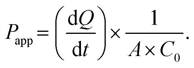 | (4) |
 | (5) |
2.13. Immunofluorescence staining
The hydrogel membranes with cells were washed three times with PBS and fixed with 4% paraformaldehyde for 30 min, followed by rinsing again three times with PBS. The cells were subsequently permeabilized with 0.025% Triton X-100 for 10 min and blocked in a 1% BSA solution for 30 min. After washing three times with PBS and incubating with primary antibodies overnight at 4 °C, the cells were incubated for 1 h with the associated secondary antibody at 4 °C. Then, 2 μg mL−1 of FITC-phalloidin staining solution was added to image the cytoskeleton at room temperature after washing three times with PBS. The cells were stained for 15 min at 37 °C and washed three times with PBS. Finally, the cell nuclei were stained with DAPI stain for 3 min and then washed three times with PBS. Images were obtained using a confocal microscope (Olympus, FV3000, Japan), and image processing was done with the Fiji software (USA).2.14. Analysis of cellular secretions
To analyze cell secretions, the medium was collected from the liquid and air chambers of each chip after 8 h of static or dynamic culture, respectively. The concentrations of Col-I, Col-IV, ET-1, ICAM-1, and NO in the culture medium were measured using the appropriate human ELISA kits according to the manufacturer's protocols.2.15. Statistical analysis
Statistical analyses were conducted using Microsoft Office Excel (USA) and SPSS statistics software (IBM, USA). All data were presented as means ± standard deviations from three independent experiments. Data and images from all cellular experiments were analyzed by using three batches of different cells. Two-tailed unpaired Student's t-test was used to assess the significance of differences, p < 0.05 was considered significant (*p < 0.05, **p < 0.01, and ***p < 0.001).3. Results and discussion
3.1. Fabrication of sac-like hydrogel membranes
Inspired by soap bubble formation, we present a versatile one-step methodology for obtaining sac-like hydrogel membranes that are similar to real tissue barriers. Utilizing a syringe pump, a pre-gel solution was first aspirated into the tip of the pipe at a defined volume. Then, it gradually expanded into a sac-like liquid membrane with an increase of the air pressure inside. Under the balance of surface tension, air pressure, and gravity, the liquid membrane was homogeneously distributed at an even thickness, and could be rapidly gelated under UV irradiation. This method was applicable to various photoinitiated hydrogels, including di-acrylated F127-DA, Gel-MA, and di-acrylated poly(ethylene glycol) (PEG-DA), demonstrating its versatility (Fig. S3A†).Basement membranes applied in OOC platforms are generally subjected to long-term airflow and fluid flow.29 Therefore, it is crucial to have a robust and secure connection between the hydrogel membrane and the supporting pipes. The utilization of BP as a UV grafting agent created tight bindings between the hydrogel membrane and the highly reactive elastomeric polyurethane (PU) and polyvinyl chloride (PVC) pipes (Fig. S3B†), but not between the membrane and the highly inert pipes, like polypropylene (PP) and polyethylene (PE) (Fig. S3C†).30 Among the various hydrogel materials and pipes, the F127-DA hydrogel membrane exhibited the highest bursting strength when a PU pipe was employed, indicating the tightest binding at the interface (Fig. 2A). It seemed that the combination of the F127-DA hydrogel with a PU pipe was the most appropriate for constructing the OOC systems.
 | ||
| Fig. 2 Fabrication of sac-like hydrogel membranes with different hydrogels and pipes. A) Bursting strength of hydrogels (15 wt% F127-DA, 15 wt% Gel-MA, and 15 wt% PEG-DA with 0.5 wt% Irgacure 2959) when employing PU and PVC pipes. ***p < 0.001. B–D) Thickness at each position of the F127-DA hydrogel membranes when employing pipes of varying diameters, wall thicknesses, and materials. E) Thickness of a F127-DA hydrogel membrane prepared using the smallest PU pipe (OD = 1 mm, ID = 0.7 mm). F) F127-DA hydrogel membrane observed using optical microscopy (scale bar: 150 μm). | ||
Hydrogel membranes fabricated with the use of PU pipes (Fig. 2B) or PVC pipes (Fig. 2C and D) can be characterized by the variations in their inner-diameter (ID), outer-diameter (OD), and wall thickness. Thus, the flexible employment of pipes of varying diameters and wall thicknesses allowed the fabrication of hydrogel membranes with specifically designed dimensions and thicknesses, accommodating the requirements of individual applications (Fig. S3D†). With the application of the smallest PU pipe (OD = 1 mm, ID = 0.7 mm) available in our lab, the fabricated F127-DA hydrogel membrane had a thickness of 150 μm (Fig. 2E and F). Although the sac-like membrane was structurally close to the predominantly spherical geometry of the native cellular microenvironment,31,32 its size and thickness deviated from that of the physiological tissue barrier due to the limited commercial availability of very small pipes. However, this could be readily overcome in the future by utilizing a custom-made thin-walled pipe as well as a more delicately controlled pressure system.
Several techniques have been established for the fabrication of flat hydrogel membranes, such as the jigging method,33 spin coating method,34 and 3D printing method.35 In contrast, the development of curved hydrogel membranes remains unexplored. Huang et al. once developed 3D porous hydrogel blocks with an inverse opal structure via a sacrificial template method for culturing epithelium cells on their inner surfaces.36 Unfortunately, this opal structure could not be used to reproduce the alveolar-capillary barrier in vivo due to the lack of an opposing surface for endothelium cell culture, rendering it inadequate as a curved hydrogel membrane. Hence, our paper, for the first time, reports the fabrication of curved hydrogel membranes. Moreover, the presented one-step methodology is defined by its simplicity and convenience without the need for the use of complicated templates.
3.2. Characterization of the sac-like F127-DA hydrogel membrane
The culture of cells on each side of the sac-like hydrogel membrane was the most important feature for establishing the tissue barriers. Although the F127-DA hydrogels are commonly used bioinert and non-fouling substrates in tissue engineering, they still needed surface modification with Col-I to improve cell adhesion.37–39 After modification, the hydrogel membrane showed a porous surface of collagen fibers (Fig. 3A and B), and thus supported cell adhesiveness (Fig. 3C). Meanwhile, the water contact angle of the modified hydrogel decreased from 64.2° ± 0.86° to 62.75° ± 1.85°, indicating improved surface hydrophilicity (Fig. 3D and E). This enhanced wettability was expected to promote cell adhesion and diffusion on the hydrogel surface.40 In addition, the modified F127-DA hydrogels had higher porosity (Fig. 3F), which would provide an expanded network of pathways for efficient nutrient and oxygen transport during layered cell culture.41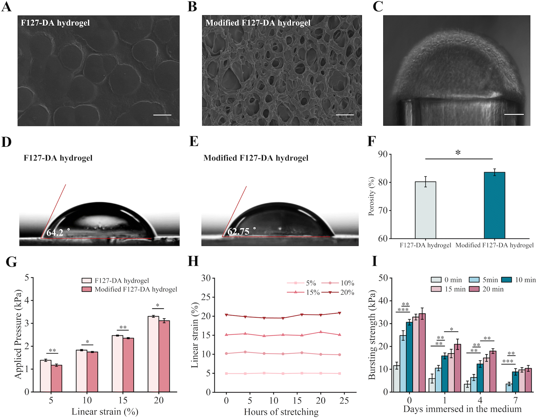 | ||
| Fig. 3 Characterization of the sac-like hydrogel membranes. A and B) SEM images of the F127-DA and modified F127-DA hydrogel (scale bar: 30 μm). C) HUVECs cultured on the outer side of the F127-DA membrane (scale bar: 150 μm). D and E) Contact angles of the F127-DA and modified F127-DA hydrogel. F) Porosity of the F127-DA and modified F127-DA hydrogel. *p < 0.05. G) Linear strain of the F127-DA and modified F127-DA hydrogel under applied pressure. *p < 0.05, **p < 0.01, and ***p < 0.001. H) Fatigue resistance of the membrane. The modified F127-DA hydrogel was cyclically stretched under cyclic airflow and liquid flow for 24 h at strains between 5–20% (0.2 Hz). I) Bursting strength of the modified F127-DA membrane immersed in a medium for 7 days after different benzophenone treatment times. *p < 0.05, **p < 0.01, and ***p < 0.001 compared to 10 min treatment groups. | ||
High mechanical stability is another important characteristic of hydrogel membranes as culture substrates. Notably, the hydrogel membrane containing 15 wt% F127-DA was obviously swollen at low temperature (4 °C) and shrank at high temperature (70 °C) but maintained its non-swelling properties under 37 °C (Fig. S4†), minimizing the potential decline in mechanical properties caused by swelling. Though coating the surface with Col-I contributed to a worsening of the mechanical properties (Fig. 3G), the modified hydrogel still showed excellent fatigue resistance during 24 h of cyclic stretching equal to 17280 cycles (Fig. 3H).
The tight connection between the F127-DA hydrogel and the supporting PU pipe, as a result of the BP pretreatment, played a crucial role in determining its ability to withstand cyclic stretching and perfusion in the tissue microenvironment. As demonstrated in Fig. 3I, the untreated pipes were completely detached from the hydrogel after 7 days of immersion in the medium, while the pipes treated for 10 min, 15 min, and 20 min maintained equivalent burst strengths of above 10 kPa. The optimal time for BP pretreatment was determined to be 10 min to minimize the potential cytotoxicity due to residual BP (Fig. S5†).
Furthermore, F127-DA hydrogel membranes were found to be highly stretchable and shrinkable. This membrane could expand over 22 times its original volume with its minimum thickness reaching lower than 5 μm (Fig. 4A and S6A†), while retaining its integrity under high pressure (Fig. 4B). Likewise, under negative pressure, it could be sucked into a pipe without membrane rupture (Fig. S6B†). It also displayed excellent puncture resistance (Fig. 4C), a property that minimized damage to the hydrogel from sharp needles during subsequent manipulations. As shown in Fig. 4D, the curved hydrogel membrane transformed from a sac-like to a flat structure after drying but could rapidly regain its curvature within 30 s of immersion in water. This property increased its storability and stability with a long storage time of over 3 months at 4 °C being possible (Fig. S6C†). These properties provide a solid foundation for large-scale industrial production, long-term preservation, and convenient applications. Meanwhile, according to our previous findings, the F127-DA hydrogel possesses a stiffness of 21.41 kPa and an oxygen permeability of 0.39 × 10⁻³ cm2 min−1, which are close to the values found in lung tissue (stiffness of 20 kPa, oxygen permeability of 0.56 × 10⁻³ cm2 min−1).42 Thus, the F127-DA hydrogel membranes with excellent properties could completely replace polymeric membranes for fabrication of curved tissue barriers in OOC platforms.
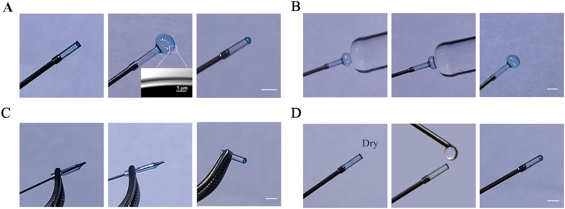 | ||
| Fig. 4 Mechanical properties and stability of the modified F127-DA hydrogel membranes. A) Flexibility. B) Compression resistance in the expanded state. C) Puncture resistance. D) Structural stability for convenient storage (scale bar: 2 mm). | ||
3.3. Representative application for establishing the alveolar-capillary barrier
The sac-like hydrogel membrane mimicked well the natural tissue barrier in both its material composition and geometry, demonstrating superior performance to flat and non-biocompatible polymer membranes when reflecting the realistic functions of tissue barriers. Here, we demonstrate a representative use of the sac-like hydrogel membrane in modeling the highly complex alveolar-capillary barrier in a lung-on-a-chip device. In this respect, the hydrogel membrane was assembled into a PDMS device which provided the medium and cyclic mechanical movements (Fig. 5A and B). The inner side of the hydrogel membrane was cultured with HPAEpiCs and was connected to a syringe pump to provide cyclic stretching (0.2 Hz, 10%). While the outer side of the membrane was cultured with HUVECs and was flowed with medium to deliver nutrients to the cells. In considering that the physiological reproduction of the cellular shear force is essential for achieving the corresponding functions,43,44 CFD simulations were performed at varying flow rates and different linear strains (Fig. S7†), identifying that a flow rate of 0.06 mL min−1 could approach the shear stress of 1 dyn cm−2 found in human endothelial capillaries.45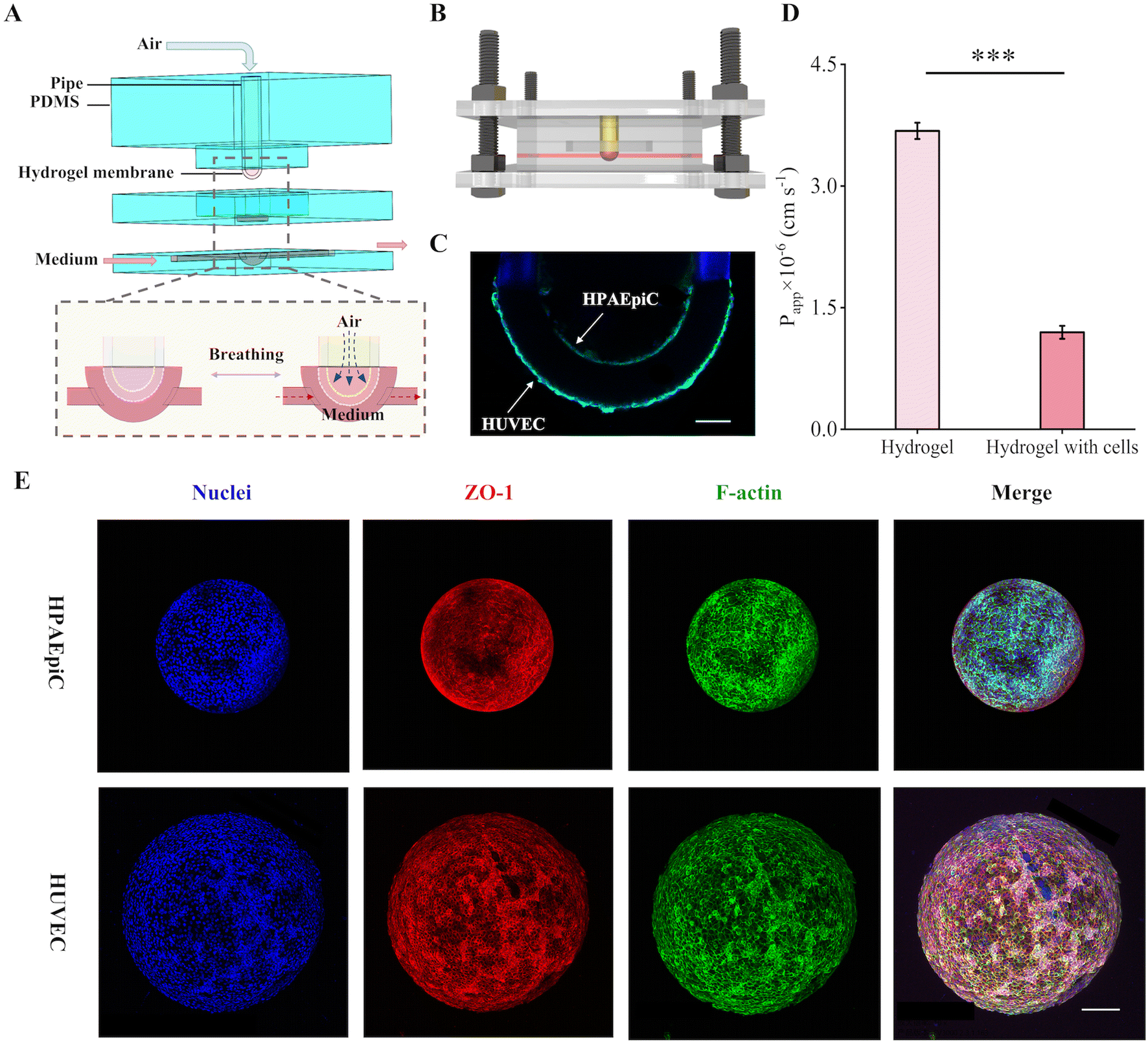 | ||
| Fig. 5 Reproduction of alveolar-capillary barrier in a lung-on-a-chip device. A) Design and structure of the lung-on-a-chip device. B) Schematic diagram of the microfluidic device. C) Confocal sectional view. The monolayer of fused cells was formed on the inner and outer sides of the membrane. Green, F-actin; blue, nuclei (scale bar: 150 μm). D) The permeability of FITC-dextran in the presence and absence of the bilayer cells after 5 days of culture. ***p < 0.001. E) Confocal reconstruction view of the HPAEpiCs and HUVECs cells after 5 days of culture. Red, ZO-1; green, F-actin; blue, nuclei (scale bar: 100 μm). | ||
In order to reproduce a functional barrier, the cells should fuse into a confluent monolayer.15,46 After the HPAEpiCs and HUVECs cells were respectively seeded by the step motor and cell scaffold, the two cells were able to grow continuously until reaching the confluence at different seeding densities (Fig. S8A and B†). The cells could maintain high cell viability within 7 days of static culture on the curved membrane surface and some could even survive for at least 12 days (Fig. S8C and D†). This device was validated for its capability to maintain the individual cultures of the HPAEpiCs and HUVECs cells on each side of the hydrogel membrane (Fig. 5C), and a significant reduction in the Papp of FITC-dextran compared to the blank membrane was observed (Fig. 5D). The cell layers alone have a Papp of 1.2 × 10⁻⁶ cm s−1 in this study and could be considered as a tight barrier.27,47 The confocal microscopy images further confirmed the formation of an alveolar-capillary barrier (Fig. 5E and Movies S1 and S2†).
The spherical geometry of the native alveolar microenvironment has been similarly mimicked on a semispherical membrane of polycarbonate (PC).15,48 However, this culture could not form the alveolar-capillary barrier due to the incompletely formed endothelial cell monolayer at the convex dome-shaped region.48 Similarly, in another work, the alveolar-capillary barrier could not be formed on a planar PDMS membrane, despite having an ultra-low elastic modulus (5 kPa) and a fibronectin coating on the surface. This was attributed to the poor covering culture of the endothelial cells on the surface.49 We hypothesized that these unsuccessful cell monolayer cultures were a result of the properties of the basement membrane material deviating far from the truly soft and wet ECM in vivo. Thus, we realistically reproduced the alveolar hemispherical structure and the alveolar-capillary barrier for the first time in a 3D lung-on-a-chip device via the use of a hydrogel as the culture substrate.36,47,50
Dynamic cell culture is recognized as a method that is more representative of physiological conditions by providing a mechanical microenvironment that closely mimics in vivo conditions.51 For HPAEpiCs, their expression on EGFR, which is normally highly expressed in tumor cells, was slightly downregulated in the dynamic culture, thus maintaining normal cell growth and proliferation (Fig. 6A and S9A†).52 The absence of expression of vimentin under both static and breathing conditions (Fig. 6B) indicated that the HPAEpiCs did not undergo epithelial-to-mesenchymal transition (EMT). Meanwhile, dynamic culture increased the expression of HPAEpiCs for SPC, Col-I, and Col-IV, enhancing mechanical crosstalk between the cells and dynamic ECM within the physiological range (Fig. 6C–E).53 With regard to the HUVECs, the cyclic strain and shear stress promoted the expression of VE-cadherin and VEGF, maintaining cytoskeletal, endothelial barrier integrity and permeability (Fig. 6F and G and S9B†).54 As shown in Fig. 6H–J, the dynamic culture of the HUVECs also significantly enhanced their expression on ET-1, ICAM-1, and NO. Additionally, the dynamic breathing effectively stimulated F-actin rearrangement and tight junction (ZO-1) secretion of HPAEpiCs and HUVECs, accelerating the formation of the alveolar-capillary barrier (Fig. S9C and D†). The cellular functions were more weakly expressed in planar membranes, particularly during respiration (Fig. S10†). Overall, hydrogel membranes with a sac-like structure supported well the confluent culture of both epithelial and endothelial cells which had highly expressed cellular functions similar to those found in vivo and that resembled the natural alveolar-capillary barrier.
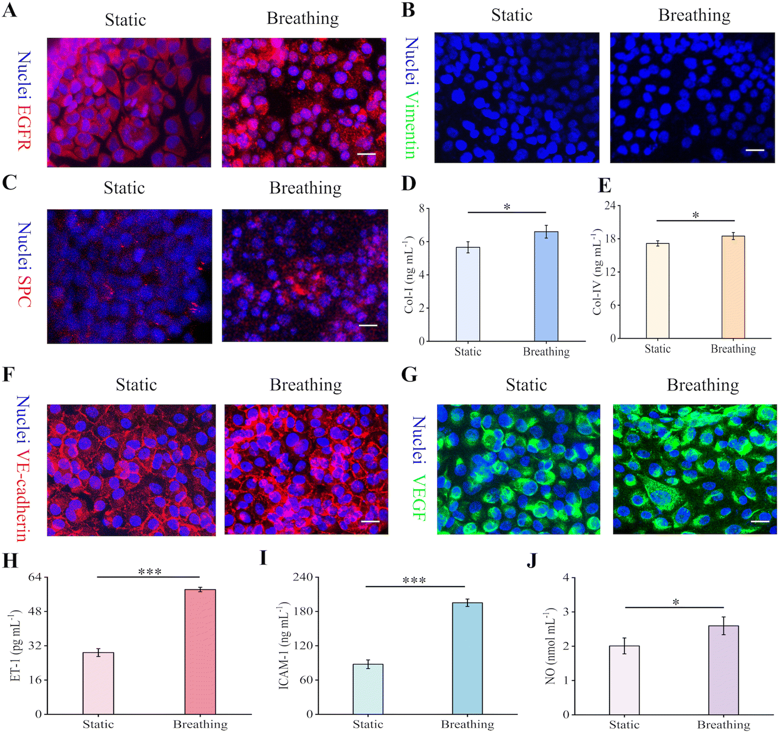 | ||
| Fig. 6 Comparison of HPAEpiCs and HUVECs cells cultured under static and breathing conditions at the ALI after 5 days of culture at the LLI. A–C) Confocal reconstruction view of the HPAEpiCs under static culture and 8 h of dynamic culture (cyclic strain of 10%, 0.2 Hz; flow rate of 0.06 mL min−1) (scale bar: 40 μm). A: Red, EGFR; blue, nuclei. B: Green, vimentin; blue, nuclei. C: Red, SPC; blue, nuclei. D and E) Col-I (D) and IV (E) secretion from the HPAEpiCs under static culture and 8 h of dynamic culture (cyclic strain of 10%, 0.2 Hz; flow rate of 0.06 mL min−1) assayed using an ELISA kit. *p < 0.05. F and G) Confocal reconstruction view of the HUVECs under static culture and 8 h of dynamic culture (cyclic strain of 10%, 0.2 Hz; flow rate of 0.06 mL min−1) (scale bar: 40 μm). F: Red, VE-cadherin; blue, nuclei. G: Green, VEGF; blue, nuclei. H–J) Secretion of ET-1 (H), ICAM-1 (I), and NO (J) from the HUVECs under static culture and 8 h of dynamic culture (cyclic strain of 10%, 0.2 Hz; flow rate of 0.06 mL min−1) assayed using an ELISA kit. *p < 0.05 and ***p < 0.001. | ||
3.4. The potential application of sac-like hydrogel-based tissue barrier
As is well known, human tissues have a plethora of forms or shapes with a striking prevalence of round shapes or curved surfaces, particularly at the interfaces between two tissues or two fluid–fluid or air–fluid chambers. The round/curved surface elicits differential biological or physiological functions via regulating biomechanical forces.17 Generally, the mechanical force can be strongly experienced by epithelial and endothelial cells lined on the curved surfaces of the mall acinar or tubular lumens,15 including the lung alveoli, cornea, retina, glomerulus and glandular vesicles. Nevertheless, current cell or tissue cultures are generally conducted on flat surfaces and therefore curved substrates are required to reflect the physiological microenvironment of cells in vivo.17,18,55 Furthermore, cell function and behavior are also closely related to the dynamic changing forces and curvatures of organs in vivo,56 like the heart or lungs. The appropriate growth and functions of cells in the curved tissue barrier under rhythmic movement require special hydrophilic and elastic material properties,57 which are not provided by PDMS or PC.18,58 Hydrogels not only offer great opportunities to facilitate the culture of cells/tissues by integrating with microscale technology and cell biology and by accurate simulation of the ECM,14,59 but also they present advantages in drug development due to their low absorbance of small hydrophobic molecules in comparison with PDMS and PC.18,58The sac-like hydrogel membrane demonstrated in this paper and its representative application in mimicking the alveolar-capillary barrier could pave the way for the construction of other tissue barriers featuring round/curved-like geometrical interfaces. With further dedicated manipulation of the geometric shape (thickness, size, and shape) of the hydrogel membrane, it could be more diversely regulated to entirely replicate specific curved tissue-barriers in the human body.17 This could be achieved by improving the fabrication technique by customizing the small elastomeric pipe and by more accurately controlling the airflow. With such developments, the blood–retina barrier, glomerular filtration barrier, and even the heart blood-tissue barrier with dynamical changes of force and shape could be readily constructed.
This hydrogel tissue barrier can be further assembled into other OOC systems following the formula for creating this lung-on-a-chip device. For example, the curved glomerular filtration barrier could serve as critical support for establishing a kidney-on-a-chip device,23,24 while the incorporation of a corneal barrier and blood–retinal barrier is essential to the establishment of an eye-on-a-chip system.19–22 The findings in this paper could elicit interest in building OOC systems for drug discovery and tissue engineering, providing a fundamental platform for the pathological study of diseases as well as relevant drug development. Hence, the sac-like hydrogel membrane will facilitate the rapid development of OOC devices for the study of pathological disease and drug discovery.
4. Conclusion
Inspired by soap bubbles, we developed a one-step methodology to create sac-like hydrogel membranes for the reproduction of tissue barriers. The sac-like hydrogel membranes were conveniently produced by selecting an appropriate pipe (diameter and wall thickness), airflow pressure, and hydrogel material. The established sac-like hydrogel membrane was used for the construction of a lung-on-a-chip device which was capable of withstanding mechanical stretching and airflow for at least 24 h. In this lung-on-a-chip device, HPAEpiCs and HUVECs cells were individually grown on the top/bottom side of the sac-like hydrogel membrane and expressed epithelial/endothelial function under physiological respiratory conditions, recreating the pulmonary alveolar-capillary barrier. The proposed fabrication methodology in this paper provides a novel platform for replicating the natural sac-like tissue barrier and can be extended to a variety of tissue barriers or OOC systems for the study of pathological disease, drug discovery, and artificial organs.Author contributions
Wenqi She: data curation, formal analysis, investigation, methodology, resources, software, visualization, writing – original draft. Chong Shen: conceptualization, methodology, supervision, writing – review & editing. Yinghua Ying: conceptualization, investigation, methodology. Qin Meng: conceptualization, funding acquisition, project administration, supervision, writing – review & editing.Conflicts of interest
There are no conflicts to declare.Acknowledgements
We gratefully acknowledge the financial support of this study by National Natural Science Foundation of China (No. 22078287 and No. 21978257).References
- C. Strelez, H. Y. Jiang and S. M. Mumenthaler, Trends Biotechnol., 2023, 41, 278–280 CrossRef CAS.
- H. Liu, Y. Wang, K. Cui, Y. Guo, X. Zhang and J. Qin, Adv. Mater., 2019, 31, e1902042 CrossRef PubMed.
- Y. Wang, P. Wang and J. Qin, Adv. Sci., 2022, 9, e2105187 CrossRef.
- M. Zhang, P. Wang, R. H. Luo, Y. Q. Wang, Z. Y. Li, Y. Q. Guo, Y. L. Yao, M. H. Li, T. T. Tao, W. W. Chen, J. B. Han, H. T. Liu, K. L. Cui, X. Zhang, Y. T. Zheng and J. H. Qin, Adv. Sci., 2021, 8, 2002928 CrossRef CAS.
- D. Huh, B. D. Matthews, A. Mammoto, M. Montoya-Zavala, H. Y. Hsin and D. E. Ingber, Science, 2010, 328, 1662–1668 CrossRef CAS.
- V. V. Thacker, K. Sharma, N. Dhar, G. F. Mancini, J. Sordet-Dessimoz and J. D. McKinney, EMBO Rep., 2021, 22, e52744 CrossRef CAS PubMed.
- H. M. Lv, J. Dong, Y. Qiu, Y. Yang and Y. G. Zhu, Lab Chip, 2020, 20, 2394–2402 RSC.
- J. C. Mejias, M. R. Nelson, O. Liseth and K. Roy, Lab Chip, 2020, 20, 3601–3611 RSC.
- V. V. Thacker, K. Sharma, N. Dhar, G. F. Mancini, J. Sordet-Dessimoz and J. D. McKinney, EMBO Rep., 2021, 22, e52744 CrossRef CAS.
- Y. J. Zhu, L. Y. Sun, Y. Wang, L. J. Cai, Z. H. Zhang, Y. X. Shang and Y. J. Zhao, Adv. Mater., 2022, 34, 2108972 CrossRef CAS PubMed.
- Y. H. Wei, K. Z. Wang, S. H. Luo, F. Li, X. L. Zuo, C. H. Fan and Q. Li, Small, 2022, 18, 2107640 CrossRef CAS.
- J. Lou and D. J. Mooney, Nat. Rev. Chem., 2022, 6, 726–744 CrossRef CAS PubMed.
- G. Salimbeigi, N. E. Vrana, A. M. Ghaemmaghami, P. Y. Huri and G. B. McGuinness, Mater. Today Bio, 2022, 15, 726–744 Search PubMed.
- H. T. Liu, Y. Q. Wang, K. L. Cui, Y. Q. Guo, X. Zhang and J. H. Qin, Adv. Mater., 2019, 31, 1902042 CrossRef CAS PubMed.
- D. Baptista, L. M. Teixeira, Z. T. Birgani, S. van Riet, T. Pasman, A. Poot, D. Stamatialis, R. J. Rottier, P. S. Hiemstra, P. Habibovic, C. van Blitterswijk, S. Giselbrecht and R. Truckenmuller, Biomaterials, 2021, 266, 120436 CrossRef CAS PubMed.
- C. J. Connon and R. M. Gouveia, Adv. Biol., 2021, 5, e2000280 CrossRef.
- D. Baptista, L. Teixeira, C. van Blitterswijk, S. Giselbrecht and R. Truckenmuller, Trends Biotechnol., 2019, 37, 838–854 CrossRef CAS.
- D. Baptista, L. M. Teixeira, Z. T. Birgani, S. van Riet, T. Pasman, A. Poot, D. Stamatialis, R. J. Rottier, P. S. Hiemstra, P. Habibovic, C. van Blitterswijk, S. Giselbrecht and R. Truckenmuller, Biomaterials, 2021, 266, 120436 CrossRef CAS.
- R. Abdalkader and K. I. Kamei, Lab Chip, 2020, 20, 1410–1417 RSC.
- Z. Yu, R. Hao, J. Du, X. Wu, X. Chen, Y. Zhang, W. Li, Z. Gu and H. Yang, iScience, 2022, 25, 104200 CrossRef CAS PubMed.
- Y. B. Arik, W. Buijsman, J. Loessberg-Zahl, C. Cuartas-Velez, C. Veenstra, S. Logtenberg, A. M. Grobbink, P. Bergveld, G. Gagliardi, A. I. den Hollander, N. Bosschaart, A. van den Berg, R. Passier and A. D. van der Meer, Lab Chip, 2021, 21, 272–283 RSC.
- H. Ragelle, K. Dernick, S. Khemais, C. Keppler, L. Cousin, Y. Farouz, C. Louche, S. Fauser, S. Kustermann, M. W. Tibbitt and P. D. Westenskow, Adv. Healthcare Mater., 2020, 9, e2001531 CrossRef.
- M. G. Valverde, L. S. Mille, K. P. Figler, E. Cervantes, V. Y. Li, J. V. Bonventre, R. Masereeuw and Y. S. Zhang, Nat. Rev. Nephrol., 2022, 18, 241–257 CrossRef PubMed.
- A. Petrosyan, P. Cravedi, V. Villani, A. Angeletti, J. Manrique, A. Renieri, R. E. De Filippo, L. Perin and S. Da Sacco, Nat. Commun., 2019, 10, 3656 CrossRef.
- Q. Meng, Y. Wang, Y. Li and C. Shen, Biotechnol. Bioeng., 2021, 118, 612–621 CrossRef CAS.
- S. Khan and N. Anwar, Carbohydr. Polym., 2021, 257, 117617 CrossRef CAS.
- J. D. Stucki, N. Hobi, A. Galimov, A. O. Stucki, N. Schneider-Daum, C. M. Lehr, H. Huwer, M. Frick, M. Funke-Chambour, T. Geiser and O. T. Guenat, Sci. Rep., 2018, 8, 14359 CrossRef PubMed.
- A. Doryab and O. Schmid, Eur. J. Pharm. Sci., 2022, 179, 106305 CrossRef CAS.
- G. Vunjak-Novakovic, K. Ronaldson-Bouchard and M. Radisic, Cell, 2021, 184, 4597–4611 CrossRef CAS.
- Y. Yu, H. Yuk, G. A. Parada, Y. Wu, X. Liu, C. S. Nabzdyk, K. Youcef-Toumi, J. Zang and X. Zhao, Adv. Mater., 2019, 31, 1807101 CrossRef.
- D. Schwenninger, K. Moller, H. Liu and J. Guttmann, IEEE Trans. Biomed. Eng., 2010, 57, 415–421 Search PubMed.
- J. E. Hansen and E. P. Ampaya, J. Appl. Physiol., 1975, 38, 990–995 CrossRef CAS.
- H. C. Yu, X. P. Hao, C. A. W. Zhang, S. Y. Zheng, M. Du, S. M. Liang, Z. L. Wu and Q. Zheng, Small, 2021, 17, 2103836 CrossRef CAS PubMed.
- S. Y. Zheng, Y. Tian, X. N. Zhang, M. Du, Y. H. Song, Z. L. Wu and Q. Zheng, Soft Matter, 2018, 14, 5888–5897 RSC.
- A. Gevorkian, S. M. Morozova, S. Kheiri, N. Khuu, H. Y. Chen, E. Young, N. Yan and E. Kumacheva, Adv. Funct. Mater., 2021, 31, 2010743 CrossRef CAS.
- D. Huang, T. T. Liu, J. L. Liao, S. Maharjan, X. Xie, M. Perez, I. Anaya, S. W. Wang, A. T. Mayer, Z. X. Kang, W. J. Kong, V. L. Mainardi, C. E. Garciamendez-Mijares, G. G. Martinez, M. Moretti, W. J. Zhang, Z. Z. Gu, A. M. Ghaemmaghami and Y. S. Zhang, Proc. Natl. Acad. Sci. U. S. A., 2021, 118, e2016146118 CrossRef CAS.
- Z. T. Bao, Z. P. Gu, J. B. Xu, M. Zhao, G. T. Liu and J. Wu, Chem. Eng. J., 2020, 396, 125353 CrossRef CAS.
- P. Ren, H. Zhang, Z. Dai, F. Ren, Y. Wu, R. Hou, Y. Zhu and J. Fu, J. Mater. Chem. B, 2019, 7, 5490–5501 RSC.
- M. Li, R. Wei, C. Liu, H. Fang, W. Yang, Y. Wang, Y. Xian, K. Zhang, Y. He and X. Zhou, Bioact. Mater., 2023, 25, 333–346 CAS.
- Y. Arima and H. Iwata, Biomaterials, 2007, 28, 3074–3082 CrossRef CAS PubMed.
- J. L. Hernandez and K. A. Woodrow, Adv. Healthcare Mater., 2022, 11, e2102087 CrossRef.
- C. Shen, H. Yang, W. She and Q. Meng, Biotechnol. Bioeng., 2023, 120, 2027–2038 CrossRef CAS.
- B. M. Baker and C. S. Chen, J. Cell Sci., 2012, 125, 3015–3024 CAS.
- Y. Q. Wang, P. Wang and J. H. Qin, Acc. Chem. Res., 2021, 54, 3550–3562 CrossRef CAS.
- P. Balogh and P. Bagchi, Physiol. Rep., 2019, 7, e14067 CrossRef.
- J. B. Zhang, V. Hernandez-Gordillo, M. Trapecar, C. Wright, M. Taketani, K. Schneider, W. L. Chen, E. Stas, D. T. Breault, R. L. Carrier, C. A. Voigt and L. G. Griffith, Nat. Protoc., 2021, 16, 3874–3900 CrossRef CAS PubMed.
- P. Zamprogno, S. Wuthrich, S. Achenbach, G. Thoma, J. D. Stucki, N. Hobi, N. Schneider-Daum, C. M. Lehr, H. Huwer, T. Geiser, R. A. Schmid and O. T. Guenat, Commun. Biol., 2021, 4, 168 CrossRef CAS PubMed.
- D. Baptista, L. Moreira Teixeira, D. Barata, Z. Tahmasebi Birgani, J. King, S. van Riet, T. Pasman, A. A. Poot, D. Stamatialis, R. J. Rottier, P. S. Hiemstra, A. Carlier, C. van Blitterswijk, P. Habibovic, S. Giselbrecht and R. Truckenmuller, ACS Biomater. Sci. Eng., 2022, 8, 2684–2699 CrossRef CAS.
- M. L. Rathod, J. Ahn, B. Saha, P. Purwar, Y. Lee, N. L. Jeon and J. Lee, ACS Appl. Mater. Interfaces, 2018, 10, 40388–40400 CrossRef CAS.
- D. Baptista, L. M. Teixeira, D. Barata, Z. T. Birgani, J. King, S. van Riet, T. Pasman, A. A. Poot, D. Stamatialis, R. J. Rottier, P. S. Hiemstra, A. Carlier, C. van Blitterswijk, P. Habibovic, S. Giselbrecht and R. Truckenmuller, ACS Biomater. Sci. Eng., 2022, 8, 2684–2699 CrossRef CAS PubMed.
- B. Yang, K. Wei, C. Loebel, K. Zhang, Q. Feng, R. Li, S. H. D. Wong, X. Xu, C. Lau, X. Chen, P. Zhao, C. Yin, J. A. Burdick, Y. Wang and L. Bian, Nat. Commun., 2021, 12, 3514 CrossRef CAS.
- R. Romano and C. Bucci, Cells, 2020, 9, 1887 CrossRef CAS PubMed.
- W. Xie, X. Wei, H. Kang, H. Jiang, Z. Chu, Y. Lin, Y. Hou and Q. Wei, Adv. Sci., 2023, 10, e2204594 CrossRef.
- J. Gavard and J. S. Gutkind, Nat. Cell Biol., 2006, 8, 1223–1234 CrossRef CAS PubMed.
- S. M. Yu, J. M. Oh, J. Lee, W. Lee-Kwon, W. Jung, F. Amblard, S. Granick and Y. K. Cho, Acta Biomater., 2018, 77, 311–321 CrossRef.
- S. J. P. Callens, R. J. C. Uyttendaele, L. E. Fratila-Apachitei and A. A. Zadpoor, Biomaterials, 2020, 232, 119739 CrossRef CAS PubMed.
- Z. Y. Jin, Y. S. Zhai, Y. Zhou, P. Guo, M. M. Chai, W. S. Tan, Y. Zhou and L. Cen, Chem. Eng. J., 2022, 448, 137739 CrossRef CAS.
- L. A. Low, C. Mummery, B. R. Berridge, C. P. Austin and D. A. Tagle, Nat. Rev. Drug Discovery, 2021, 20, 345–361 CrossRef CAS PubMed.
- M. K. Yazdi, V. Vatanpour, A. Taghizadeh, M. Taghizadeh, M. R. Ganjali, M. T. Munir, S. Habibzadeh, M. R. Saeb and M. Ghaedi, Mater. Sci. Eng., C, 2020, 114, 111023 CrossRef CAS PubMed.
Footnote |
| † Electronic supplementary information (ESI) available. See DOI: https://doi.org/10.1039/d3lc00807j |
| This journal is © The Royal Society of Chemistry 2024 |