
 Open Access Article
 This Open Access Article is licensed under a Creative Commons Attribution-Non Commercial 3.0 Unported Licence
Geometry and length control of 3D engineered heart tissues using direct laser writing†
M. Çağatay
Karakan
 abcd,
Jourdan K.
Ewoldt
cd,
Addianette J.
Segarra
be,
Subramanian
Sundaram
cd,
Miranda C.
Wang
cdf,
Alice E.
White
abcgh,
Christopher S.
Chen
cd and
Kamil L.
Ekinci
abg
abcd,
Jourdan K.
Ewoldt
cd,
Addianette J.
Segarra
be,
Subramanian
Sundaram
cd,
Miranda C.
Wang
cdf,
Alice E.
White
abcgh,
Christopher S.
Chen
cd and
Kamil L.
Ekinci
abg
aDepartment of Mechanical Engineering, Boston University, Boston, MA 02215, USA. E-mail: karakan@bu.edu
bPhotonics Center, Boston University, Boston, MA 02215, USA
cDepartment of Biomedical Engineering, Boston University, Boston, MA 02215, USA
dWyss Institute for Biologically Inspired Engineering, Harvard University, Boston, MA 02115, USA
eDepartment of Biomedical Engineering, Polytechnic University of Puerto Rico, San Juan 00918, Puerto Rico
fHarvard-MIT Program in Health Sciences and Technology, Institute for Medical Engineering and Science, Massachusetts Institute of Technology, Cambridge, MA 02139, USA
gDivision of Materials Science and Engineering, Boston University, Boston, Massachusetts 02215, USA
hDepartment of Physics, Boston University, Boston, MA 02215, USA
First published on 29th January 2024
Abstract
Geometry and mechanical characteristics of the environment surrounding the Engineered Heart Tissues (EHT) affect their structure and function. Here, we employed a 3D tissue culture platform fabricated using two-photon direct laser writing with a high degree of accuracy to control parameters that are relevant to EHT maturation. Using this platform, we first explore the effects of geometry based on two distinct shapes: a rectangular seeding well with two attachment sites, and a stadium-like seeding well with six attachment sites that are placed symmetrically along hemicylindrical membranes. The former geometry promotes uniaxial contraction of the tissues; the latter additionally induces diagonal fiber alignment. We systematically increase the length of the seeding wells for both configurations and observe a positive correlation between fiber alignment at the center of the EHTs and tissue length. With increasing length, an undesirable thinning and “necking” also emerge, leading to the failure of longer tissues over time. In the second step, we optimize the stiffness of the seeding wells and modify some of the attachment sites of the platform and the seeding parameters to achieve tissue stability for each length and geometry. Furthermore, we use the platform for electrical pacing and calcium imaging to evaluate the functional dynamics of EHTs as a function of frequency.
1 Introduction
In order to pump nutrient and oxygen containing blood to the entire body, the heart's myocardium must contract in a synchronous and coherent manner. When the organization of the contractile machinery in myocardial tissue is disrupted, it can interrupt effective pumping and result in heart failure. This contractile function is closely linked to structure – from the sub-cellular level to the tissue scale.1 More than a decade ago, differentiation strategies for human induced pluripotent stem cell-derived cardiomyocytes (hiPSC-CM) became available,2 and this allowed for in vitro studies of how stiffness and geometry of the environment affect the internal structure and the contractile function of individual human cardiomyocytes.3,4The field of cardiac tissue engineering has focused extensively on understanding and replicating the 3D structure–function relationship of the native heart in vitro, using engineered heart tissues (EHTs) on a smaller scale. Significant progress in developing EHTs from cardiomyocytes had been made even before the advent of hiPSC-CMs.5–7 Over the years, these studies employed 3D mechanical boundaries as a practical way to give cues to the cells for compacting and remodeling the extracellular matrix. This approach has enabled the generation of the 3D EHTs suspended between pillars,8,9 cantilevers10 or doubly-clamped wires.11,12 In these models, using two boundaries that promote uniaxial contraction is widely preferred as a design criterion, as that facilitates the formation of aligned muscle fibers across the entire tissue construct. In contrast, biaxially or isotropically compacting tissues did not display this type of organization,13 except in designs that incorporated elliptical holes in the tissues.14,15
Even though anisotropic fiber structure is one of the hallmarks of the heart muscle, when structural anisotropy leads to high-stress areas, particularly in actively contracting tissues, it can cause the tissues to fall apart.16 For instance, in the work of Abilez et al., varying the spacing between 3D posts from 5 mm to 7 mm yielded more aligned sarcomeres inside EHTs, but further increasing the distance to 9 mm led to extreme axial stresses within the tissue, causing the generated heart tissues to fail.17 The study used the same number of cells for each tissue dimension; therefore, scaling the length between the posts translated to higher strain levels within the tissue after the anisotropic compaction process. In a study by Petersen et al. of 2D EHT strands composed of neonatal rat cardiomyocytes, their width was scaled instead of their length, showing higher calcium propagation velocities for narrower strands.18 However, Petersen et al.'s work was limited due to its 2D nature, and it was not possible to measure and compare contractile dynamics for different EHT architectures. A few studies compared the effect of cell number on EHT function and reported that the contractile output was not necessarily proportional to the number of hiPSC-CMs within the EHTs.19,20 To our knowledge, however, previous studies did not typically scale the size of the EHTs proportionally with the number of cells, likely due to the challenges of customization of the mechanical boundaries, length, and geometry of the 3D EHTs.
The primary objective of this study is to explore the effects of size and geometry of the EHTs and mechanical properties of the EHT environment on the stability, structure, and function of 3D human EHTs. We have built upon our previously developed heart-on-a-chip platform.21 Using a microfabrication strategy based on two-photon direct laser writing (DLW), we enable the generation and comparative studies of 3D EHTs of various lengths, aspect ratios, and cell numbers. In the first set of devices, we generated tissues with a small number of cells confined in a stiff seeding well with 3D-printed attachment sites. In these EHTs, we observed that a higher aspect ratio correlated with a high degree of alignment at the center, but we also observed “necking”, which led to the failure of the longer tissues. In the second set of devices, we sought to achieve stable tissues by tuning the boundaries for optimal geometric and mechanical cues. We used DLW to (i) fabricate softer and deeper seeding wells, to increase the amount of extracellular matrix and cells collected in the cavities and, (ii) to make longer attachment sites for accommodating and maintaining longer EHTs. Optimizing the platform and using more cells led to the self-assembly of more stable and functional EHTs. After achieving stable EHTs, we used our platform to assess the contractile forces and calcium dynamics of the EHTs over physiologically relevant beating rates.
Our versatile technique enables a high degree of control and rapid customization over the length and geometry of the 3D EHTs generated using the platform. Our iterative approach allows us to optimize the geometric and mechanical parameters for guiding the cell-hydrogel mixture into the self-assembly of stable 3D EHTs. By thoroughly investigating the contractile motion of EHTs with various sizes and geometries, including local contractions of individual EHTs across multiple attachment sites, this study provides valuable insights into the structure–function relationship of muscle tissues. In addition, the platform is compatible with electrical or mechanical stimulation, and calcium imaging techniques for further assessment and maturation of EHTs.
2 Methods
2.1 Device design and fabrication
A negative mold was designed using SolidWorks (Dassault Systèmes, Providence, RI) software. The fabrication procedure is based on our previous work21 with some enhancements to improve throughput. This modified design and protocol allowed fabrication of 32 wells per mold, which improves the throughput by 8×. Details of the mold design and its fabrication can be found in the ESI† (see Fig. S1). Each chip is designed to have 2 × 4 individual seeding wells with 0.8 mm, 1 mm, 1.2 mm, and 1.4 mm lengths in the stadium-like configuration with hemicylindrical membranes, and 0.5 mm, 1 mm, 1.5 mm, and 2 mm lengths in the more traditional uniaxial configuration with rectangular membranes, where the uniaxial design allows for the generation of tissues with higher aspect ratios. Some expected properties and parameters of the designs are presented in Table 1.| Type | L (mm) | L/W | V stiff (μL) | V soft (μL) | # of cellsstiff (×103) | # of cellssoft (×103) | k eff,stiff (N m−1) | k eff,soft (N m−1) |
|---|---|---|---|---|---|---|---|---|
| Rectangular | 0.5 | 1.6 | 0.13 | 0.17 | 20.4 | 40 | 39.1 | 25.6 |
| Rectangular | 1 | 3.3 | 0.25 | 0.32 | 39.4 | 75.6 | 39.1 | 25.6 |
| Rectangular | 1.5 | 5 | 0.38 | 0.47 | 59.8 | 110.9 | 39.1 | 25.6 |
| Rectangular | 2 | 6.6 | 0.51 | 0.62 | 80.3 | 146.4 | 39.1 | 25.6 |
| Stadium-like | 0.8 | 1.6 | 0.26 | 0.31 | 34.2 | 61.2 | 22–25 | 19–22 |
| Stadium-like | 1 | 2 | 0.34 | 0.41 | 44.7 | 80.8 | 22–25 | 19–22 |
| Stadium-like | 1.2 | 2.4 | 0.42 | 0.5 | 55.2 | 98.6 | 22–25 | 19–22 |
| Stadium-like | 1.4 | 2.8 | 0.5 | 0.6 | 65.7 | 118.2 | 22–25 | 19–22 |
After the fabrication of the mold using DLW and its silanization to prevent adhesion between polydimethylsiloxane (PDMS) and the mold (Fig. 1A-i, ii), PDMS (1![[thin space (1/6-em)]](https://www.rsc.org/images/entities/char_2009.gif) :10 Sylgard 184) was cast onto negative master molds and degassed for at least 30 minutes. Subsequently, a square microscope slide cut to 25 × 25 or 30 × 30 mm2 was gently placed on top of the mold. The PDMS, loosely sandwiched between the mold and the glass, was degassed again for at least 30 minutes, until there were no visible air bubbles. Afterward, weights were added onto the glass, and the samples were baked on a hot plate at 130 °C for 20 minutes (Fig. 1A-iii). Cooled samples were placed into an isopropanol bath for 10 minutes for lubrication, and then PDMS was gently removed from the mold under a stereo microscope. After demolding, the seeding wells and their thin walls were inspected under an optical microscope. Occasionally, a thin film of PDMS was observed on the top of an individual seeding well. In this case, the layer was carefully peeled off under a microscope using a sharp tweezer. Next, the PDMS was cut into individual devices.
:10 Sylgard 184) was cast onto negative master molds and degassed for at least 30 minutes. Subsequently, a square microscope slide cut to 25 × 25 or 30 × 30 mm2 was gently placed on top of the mold. The PDMS, loosely sandwiched between the mold and the glass, was degassed again for at least 30 minutes, until there were no visible air bubbles. Afterward, weights were added onto the glass, and the samples were baked on a hot plate at 130 °C for 20 minutes (Fig. 1A-iii). Cooled samples were placed into an isopropanol bath for 10 minutes for lubrication, and then PDMS was gently removed from the mold under a stereo microscope. After demolding, the seeding wells and their thin walls were inspected under an optical microscope. Occasionally, a thin film of PDMS was observed on the top of an individual seeding well. In this case, the layer was carefully peeled off under a microscope using a sharp tweezer. Next, the PDMS was cut into individual devices.
 | ||
| Fig. 1 Fabrication process of tailor-made seeding wells. (A) (i) Negative master molds are fabricated via DLW lithography on silicon substrates functionalized with an adhesion promoter. (ii) After rinsing, molds are functionalized with fluorosilane to prevent adhesion. (iii) PDMS is cast and sandwiched between mold and glass to generate the device with open seeding wells. (iv) After the device is demolded and functionalized with an adhesion promoter, cages are printed on the inner walls of the seeding wells via DLW. (v) The device is bonded to a glass bottom petri dish, then a thicker piece of PDMS is bonded on top to generate a macroscopic seeding well. Brightfield images of the tailor-made (B) rectangular and (C) stadium-like cavities after finishing the fabrication process. (D) Simulated deformations of the 0.3 mm tall membrane and the displacements of attachment sites upon the application of 100 μN force. | ||
Once the PDMS devices were formed as described above and cleaned, they were treated with 3(trimethoxysilyl)propyl acrylate (TMPA) to ensure adhesion between the PDMS sidewalls and the DLW printed attachment sites. After 30 seconds of plasma treatment, TMPA was dropcast onto the surface of the PDMS, and devices were incubated at room temperature for 15–20 minutes. The liquid TMPA was then rinsed using isopropanol and samples were gently blow-dried with a nitrogen gun. DLW of the microstructures was performed using the Nanoscribe Professional GT2 with pentaerythritol triacrylate (PETA) mixed with 3 weight % Irgacure 819 (BASF) photoinitiator. A small droplet of PETA was added to a thick cover glass, and the PDMS substrate was placed on top of the secured cover glass. After observing the resin filling the open seeding wells and coming out to the surface via capillary action, an additional droplet of PETA was placed on top of the PDMS substrate to ensure that there was enough resin between the sample and lens throughout the process of dip-in laser lithography (see Fig. 1A-iv). The subtle but important details of in situ printing of the attachment sites to the sidewalls of the PDMS membranes are described in the ESI† (see Fig. S2).
The PDMS devices with the 3D printed attachment sites were plasma treated and directly bonded to a glass bottom petri dish, which provides the optical quality and working distance for high-resolution imaging of the generated tissues. Next, a macroscopic seeding well with the cavity dimensions of 7.5 × 12 × 5 mm3 was fabricated by 3D printing a mold (Formlabs 2, Clear resin) and using the standard PDMS (1:10 Sylgard 184) casting techniques. This large seeding well serves as a common container for all the tissues inside a chip (see Fig. 1A-v), and it is bonded on top of the PDMS device layer after plasma treating both surfaces (Herrick Plasma, 10.5 W RF power, 30–45 seconds). After this bonding step, the PDMS–PDMS and glass PDMS interfaces were sealed using liquid PDMS (1:10 Sylgard 184) to prevent any leakage.
Representative top-view images of the individual cavities from completed devices are shown in Fig. 1B and C. Rectangular cavities displayed in Fig. 1B have the same widths of 0.5 mm, and the length varies by 0.5 mm increments. Considering the 0.3 mm width of the attachment sites, we expect the generation of EHTs with the aspect ratios (L/W) of 1.6, 3.3, 5.5, and 6.6. Fig. 1C shows the circular to stadium-like cavities with 6 attachment sites, where 3 cage microstructures were placed on each side of the deformable hemicylindrical membranes. We introduce anisotropy into these EHT designs with 0.2 mm increments in the longitudinal direction. Considering the ≈0.5 mm distance between the diagonal attachment sites, the expected aspect ratios (L/W) of the tissues generated by this design are 1.6, 2, 2.4, and 2.8. An important distinction to note is the stiffness keff of these membranes. Even though the thickness and the height of these membranes are the same (25 μm and 0.3 mm respectively), the different widths and geometries result in different stiffnesses in response to the contractile forces applied upon the attachment sites. We built upon our experimentally verified previous finite element model21 to estimate the effective spring constant of the platform.
2.2 Finite element model
Finite element modeling of the devices is carried out using COMSOL Multiphysics (version 6.1, Solid Mechanics Module, COMSOL, Inc.). Meshes were generated using tetrahedral elements and the “extra fine” setting to determine the element size. Young's moduli of PDMS and PETA are taken as 2.2 MPa and 260 MPa respectively;22,23 Poisson's ratio of PDMS is taken as 0.48 (ref. 24) and of PETA as 0.40. To mimic adhesion between PDMS and the bottom glass surface, we assume a fixed boundary at the bottom surface of the model and keep the rest of the boundaries in the model free. To simulate contractile forces exerted by the tissue, we applied normal outward forces between 40 μN and 500 μN on each of the circular surfaces of the cylindrical PETA cages. Fig. 1D shows a case where 100 μN forces were applied normally outward from the surface of the cages in both geometries. To estimate the spring constant, we calculated the slope between applied force and observed displacement, |Δr| = keff−1F or Δx = keff−1F (see Fig. S3†). Simulations suggest that rectangular membranes are 1.2–1.6× stiffer than hemicylindrical membranes depending on the configuration.2.3 hiPSC and hMSC cell culture, and cardiomyocyte differentiation
The human induced pluripotent stem cells (hiPSCs) featured in this study were created from the PGP1 donor from the Personal Genome Project and edited to have an endogenous green fluorescent protein tag on one titin allele (gift from Seidman Lab at Harvard Medical School).25 Results from a second cell line, GSB-L550 (SCVIi001-A) from Greenstone Biosciences, which is created from a patient with hypertrophic cardiomyopathy, are included for comparison in Fig. S8.†26 HiPSCs from the second cell line were maintained in complete mTeSR1 medium (Stem Cell) on Matrigel (Fisher) mixed 1:80 in DMEM/F-12 (Fisher) and split using Accutase (Sigma) at 70–90% confluence. Once hiPSCs reached >90% confluence, they were differentiated to the cardiomyocyte lineage in RPMI 1640 medium (Gibco) supplemented with B27 minus insulin (ThermoFisher) and 1× GlutaMax (Fisher) by sequential targeting of the WNT pathway – activating the WNT pathway using 12 μM CHIR99021 (Tocris) for 24 hours for PGP1, and 6 μM CHIR99021 (Tocris) for 48 hours for GSB-L550 cell lines, and inhibiting the WNT pathway using 5 μM of IWP4 (Tocris) for 48 hours on Day 3 for PGP1 and Day 2 for GSB-L550 cell lines. The basal media was changed to RPMI 1640 medium supplemented with GlutaMax and B27 with insulin (ThermoFisher) on Day 7. Cardiomyocytes were isolated after showing spontaneous beating (usually between Day 9 and Day 11) using metabolic selection by adding 4 mM of sodium DL-lactate (Sigma) in glucose-free RPMI 1640 medium (Gibco) for four days. Following selection, cardiomyocytes were replated onto fibronectin-coated plates and maintained in RPMI 1640 medium supplemented with GlutaMax and B27 and used to make cardiac tissues after 25 days (for PGP1 cell line), and 35 days (for GSB-L550 cell line) post initiation of differentiation.
Human mesenchymal stem cells (hMSCs) were isolated from a 39 year-old male and stored in low glucose Dulbecco's modified medium (DMEM, Fisher) supplemented with 10% Fetal Bovine Serum (FBS), 1% penicillin–streptomycin (P/S) (Fisher), and 10% DMSO in liquid nitrogen until further use. Cells were thawed and passaged using 0.25% trypsin–EDTA (Fisher) and cultured in low-glucose DMEM supplemented with 10% FBS and 1% P/S.
2.4 Generation of engineered heart tissues
The PDMS devices were plasma treated (EMS 1050X, EMS Quorum) in ambient air, for 60 seconds at 100 W and 0.6 mbar. Chips were then sterilized in 70% ethanol for one hour under vacuum followed by washing in sterile deionized water three times over 30 minutes under vacuum. The sterilized chips were then treated with 2% Pluronic F127 for 30 minutes at room temperature under vacuum to prevent cell-laden hydrogel adhesion to PDMS. Pluronic F127 was removed, and 100 μl of 2.25 mg ml−1 liquid-neutralized collagen I (BD Biosciences) was added to each device on ice. Devices were then centrifuged at 1200 RPM for 1.5 minutes. Excess collagen was removed and hiPSC-CMs were dissociated after trypsin digestion and mixed with hMSCs to enable tissue compaction. A suspension of 400000–600000 cells (90% cardiomyocytes and 10% hMSCs) within the collagen solution was added to each device, and devices were centrifuged again at 1200 RPM for 1.5 minutes to drive the cells into the micropatterned tissue wells. Excess collagen and cells were removed by aspiration, and devices were centrifuged a third time before incubating at 37 °C to induce collagen polymerization. The tissue culture media consisting of DMEM (Corning) with 10% FBS (Sigma), 1% GlutaMax (Gibco), 1% non-essential amino acids (Gibco), 1% penicillin–streptomycin (Gibco), and 5 μM Y-27632 was then added to the seeding well. Y-27632 was removed after one day and growth media was changed every other day thereafter. Cells compacted the collagen gel over several days and testing was performed 2–9 days post seeding.
2.5 Electrodes and electrical pacing
Electrical stimulation experiments were done 8 or 9 days after cell seeding, using two carbon rods (3 mm diameter; Ladd Research Industries) as electrodes. Two holes separated by 1 cm were drilled in a petri dish cover, the bottom parts of the electrodes were inserted, and then the hole-electrode interface was sealed with PDMS. Platinum wires were connected between the top part of the electrodes and the electrical stimulator (C-Pace EM 100, IONOPTIX). After inserting the electrodes adjacent to the inner corners of the macroscopic seeding well, EHTs were stimulated by 5 ms biphasic square pulses of 20 to 30 V cm−1 in sequence mode, and the maximum current was set to 240 mA.2.6 Immunostaining
Tissues were fixed on Day 8 or Day 9 after seeding, using a 4% paraformaldehyde (PFA) solution in culture media for 25 minutes. The PFA solution was removed, and the tissues were washed with 1× phosphate-buffered saline (PBS) three times. The cell membranes were permeabilized and blocked using a PBS solution with 0.3% Triton-X and 2% bovine serum albumin (BSA) for 1 hour at room temperature. The tissues were washed with PBS three times and were incubated overnight in primary antibody for 1:200 sarcomeric α-actinin (ab137346, Abcam) in 1% BSA at 4 °C followed by three PBS washes. Tissues were then incubated in DAPI for nuclei, phalloidin for actin, and 1:100 for the secondary antibody (A11030, Invitrogen) in 1% BSA for 1 hour at room temperature, followed by three additional washes in PBS. Olympus FV3000 scanning confocal microscope equipped with a 10× or 20× objective was used for imaging.
2.7 Calcium imaging
On Day 8 or 9, tissues were incubated with the Rhod-3 calcium imaging kit (ThermoFisher) immediately prior to imaging. Briefly, tissues were washed three times in Tyrode's buffer (ThermoFisher) and subsequently incubated in 10 μM Rhod-3 AM, PowerLoad, and Probenecid for 45 minutes. Tissues were washed in Tyrode's buffer and incubated in Probenecid for an additional 45 minutes. Tissues were then washed in Tyrode's buffer three additional times and kept in Tyrode's during live imaging.2.8 Data acquisition and processing
Time-lapse videos of the tissue contractions were acquired between 20–50 frames per s using 4× or 10× objectives on a Nikon Eclipse Ti (Nikon Instruments Inc.) with an Evolve EMCCD camera (photometrics) equipped with a temperature and CO2-equilibrated environmental chamber. These videos were then analyzed with a custom MATLAB script (provided in ESI†) that tracks displacements by looking at features with steep intensity gradients such as spots and edges. The script primarily tracks displacement along a single direction; in order to track 2D displacement, the horizontal and vertical displacement components are separately estimated by the script to compute the total displacement. First, to track displacement along a single direction, the user selects a rectangular region of interest (an image patch) containing the entirety of the feature to be tracked. In the 1D version, the direction of motion is expected to be along the horizontal direction with respect to the chosen image patch. The script finds the sharpest edge (aligned vertically) in the image patch and generates an intensity profile orthogonal to the edge. This intensity profile is used to determine a coarse pixel-level offset of the spatial intensity profiles across all frames in the horizontal direction. The coarse offset is used to align the intensity profiles. Next, a fine cross-correlation is performed at sub-pixel resolution after interpolating the intensity profiles 20×. The calculated fine-resolution offsets are used to refine the previously calculated coarse offset. Finally, to determine the exact edge offsets, the sharpest gradient is identified from the intensity profiles across all frames. Overall, the exact edge displacement is determined at progressively better resolutions: first from the coarse pixel level offset and fine frame shifts at 20× pixel resolution, and then finally refined with the remaining edge offset. We found that this 3-staged offset computation, with increasing precision at each stage, works more robustly than performing single-stage edge-tracking. For the 2D tracking version, the script performs the above tracking first along the horizontal direction and then along the vertical direction to calculate the absolute displacements. After the tissue displacements were computed, we used the estimated spring constants to determine contractile forces. We then estimated peak forces and contraction kinetics from these contractile force profiles.In calcium imaging videos, an ImageJ (NIH) plugin, MUSCLEMOTION, was used instead to generate normalized contractile behavior.27 To quantify calcium fluorescence and its dynamics from the videos, another ImageJ plugin, Spiky, was used.28 Its algorithm is based on summing the pixel intensities in a specified region for each frame of a time series video. MATLAB and OriginPro 2018 were used for data analysis. Peak detection was done either by the “findpeaks” command in MATLAB or the “Peak Analyzer” tool in Origin.
3 Results
3.1 Scaling and formation of EHTs
After the cells are seeded and centrifuged, we expect each microscopic cavity to be filled homogeneously with the same cell and collagen matrix density. Since the volumes of the cavities increase in proportion to their lengths, this technique allows for simultaneous scaling of the length of the EHTs and the number of cells in them. Furthermore, these tissues with varied parameters are all seeded at the same time, minimizing additional manual alignment and pipetting steps during tissue generation and enabling a fair comparison between tissues with different lengths, aspect ratios, and number of cells. Table 1 summarizes these dimensions and the estimated properties of the tissues. Here, each cavity has two different versions—one that is “soft” and one that is “stiff”. In the stadium-like cavities, the stiff one has a membrane height of 0.3 mm, and the soft one has a membrane height of 0.4 mm. This height difference is the same in the rectangular cavities. In addition, we increase the width of the cavity from 0.5 mm to 0.6 mm to further increase the cavity volume and decrease the stiffness experienced by the tissue. Finite element simulations estimate that the effective spring constant experienced by the cells is ∼23 μN μm−1 for stiff (short) stadium-like cavities and ∼20 μN μm−1 for soft (tall) stadium-like cavities; ∼39 μN μm−1 for stiff (short) rectangular cavities and ∼25 μN μm−1 for soft (tall) rectangular cavities respectively (see Fig. S3†). Final variable is the number of cells used between the chips with the soft and high-volume cavities (≈600000 cells, 90% hiPSC-CMs, 10% hMSCs), and stiff and low-volume seeding wells (≈400000 cells, 90% hiPSC-CMs, 10% hMSCs). Overall, our platform allows for the rapid customization of heart tissues, which could be beneficial for tailoring EHTs depending on the application.
3.2 Tissue remodeling and necking
We first used this platform to observe the formation and remodeling of the EHTs. Fig. 2 shows the temporal evolution of tissues generated in “stiff” rectangular cavities. Especially between day 2 and day 4, the static force exerted on the cage structures attached to the PDMS membrane causes a prominent bulging of the membrane in all tissues. This can be quantified by measuring bulging, or static cage displacements. This static tension seems to stabilize around day 4,consistent with the previous observations.16Fig. 2A represents a typical case for 0.5 mm long tissue generated in stiff cavities with 1.6:1 aspect ratio. We observed that most tissues undergo compaction over 4 days; between days 4 and 9, additional compaction and redistribution of cells had only subtle effects on the overall morphology. Fig. 2B shows the remodeling for a tissue with 1 mm length and 3.3:1 aspect ratio. In this example, the tissue continues to remodel, especially at the center region. Formation of the neck, which has been previously observed, is possibly due to cell-derived tension, and twitch-produced mechanical perturbations within the tissue.16,29Fig. 2C shows the situation where we further increase the length of the tissue to 1.5 mm and increase the aspect ratio to 5:1. Here, by day 9, the width of the neck was significantly smaller than the rest of the tissue with continued reduction over time. This tissue was unstable and very close to rupture due to extreme axial tension, exacerbated by the stretching of the tissue at the center region with each twitch (see Movie S1†). We were not able to produce suspended EHTs in the 2 mm rectangular cavities due to the rupture of the EHTs from one side, or stiction to the bottom of the substrate. The percentage of tissues that were still stable and contracting on day 9 was 100% for 0.5 mm, 75% for 1 mm, 25% for 1.5 mm, and 0% for the 2 mm long tissues (n = 4). Overall, the stability of the EHTs decreased as a function of tissue length or aspect ratio for both geometries (see Fig. S4† for the remodeling of the EHTs generated in stadium-like geometry).
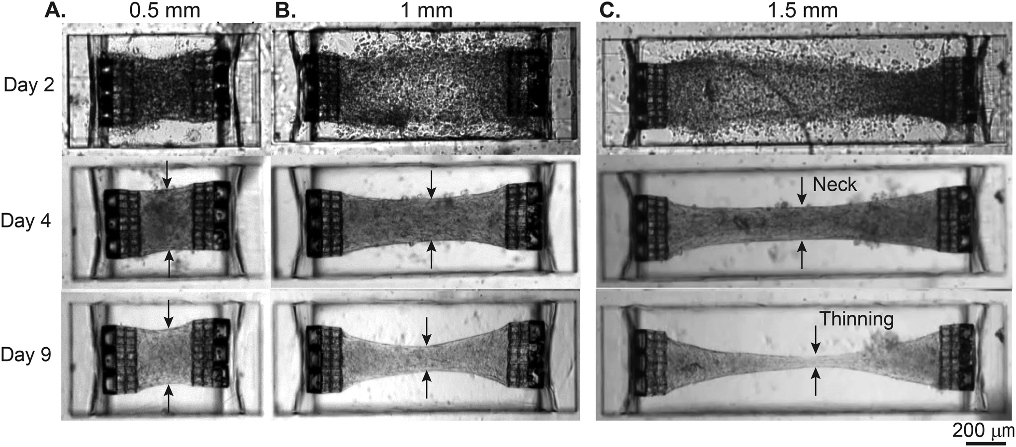 | ||
| Fig. 2 Tissue remodeling and necking inside the stiff rectangular cavities. Images for representative (A) 0.5 mm, (B) 1 mm, and (C) 1.5 mm long tissues generated in rectangular cavities over the course of 9 days. The arrows indicate the neck formation in the central region and its thinning. | ||
Considering the correlation between an increase in length and the emergence of necking and instabilities, we suggest that the increase in length and aspect ratio of the tissues is proportional to the tensile stress in the tissue. These results align with previous studies.17
3.3 Fiber alignment
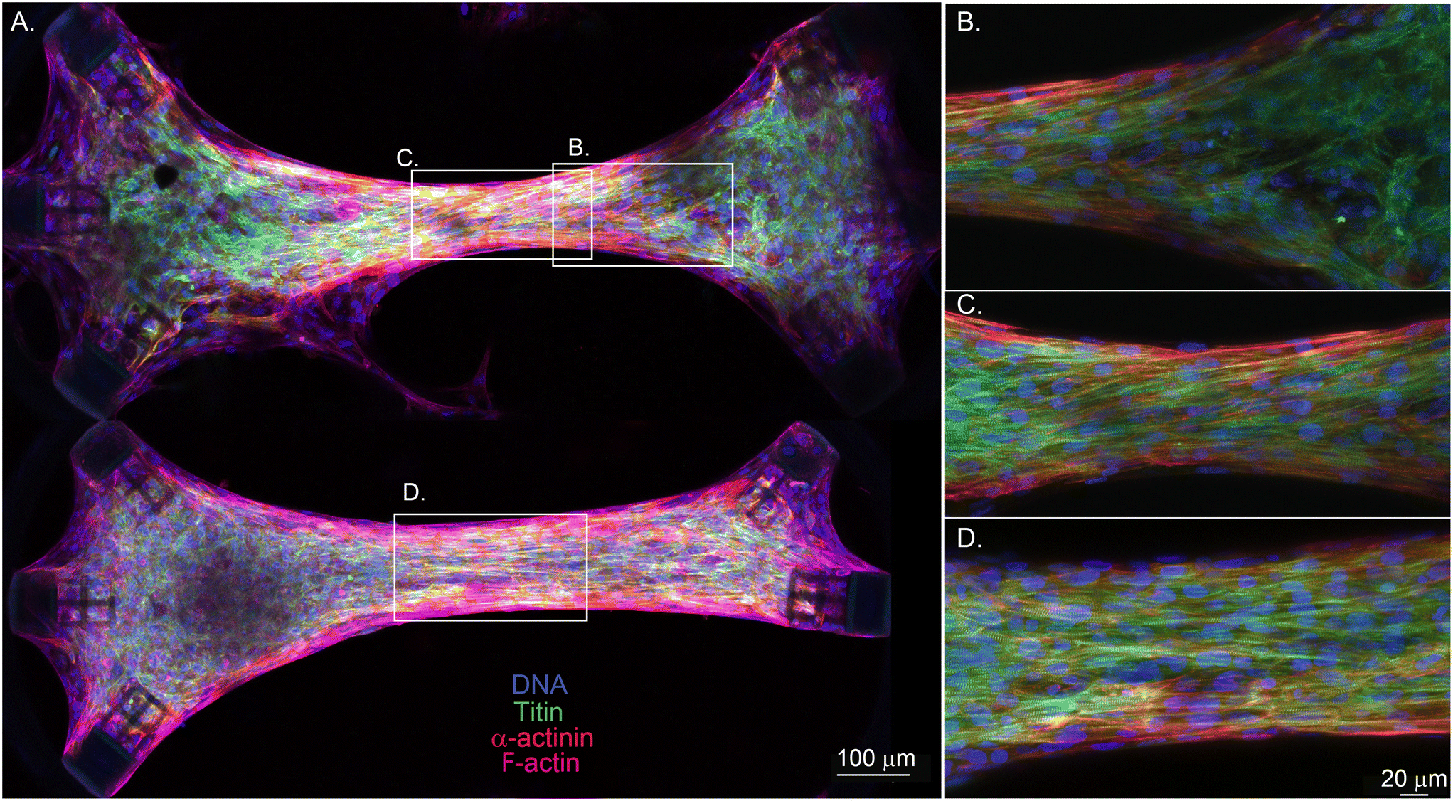
Since our goal is to tune the myofibril alignment inside EHTs for better replication of native heart muscle tissue, we also explored the impact of mechanical and geometric boundaries on cell and fiber orientation. We first analyzed the fiber structure of tissues generated in the “stiff” configuration after 9 days of tissue remodeling. After fixing the EHTs and labeling the nuclei, titin, and the α-actinin in the tissues, EHTs were imaged with a confocal microscope.
Fig. 3A shows the images taken from the centers of the (i) 0.5 mm, (ii) 1 mm, and (iii) 1.5 mm long uniaxial EHTs. The EHTs generated in rectangular cavities exhibit a higher degree of fiber alignment as the aspect ratio is increased from 1.6:1 to 3:1 and 5:1. We used Fourier analysis on the merged and Z-stack projected image of the titin and actinin channels to further quantify the direction and degree of sarcomere alignment. Here, the principal stress axis (longitudinal, 0°) was primarily defined by the placement of mechanical constraints (PDMS membranes and attachment sites). The Gaussian fits to the Fourier components in polar coordinates revealed that fiber directions peak at 12.8°, 4.9°, and 2.3° for the 0.5 mm, 1 mm, and 1.5 mm long EHTs, respectively (see Fig. 3B). The degree of alignment was inferred from the dispersion of the angles from the fiber direction; we observed a progressive increase in the degree of alignment of the fibers at the center of EHTs as the length and aspect ratio increased.
 | ||
| Fig. 3 Fiber orientation and alignment for tissues generated in stiff seeding wells. (A) Shows the immunofluorescence images of 0.5 mm (i), 1 mm (ii), and 1.5 mm (iii) long uniaxial EHTs with the aspect ratios of 1:6:1, 3:1, and 5:1 respectively (blue: nuclei, white: titin, magenta: α-actinin). The scale bar is 50 μm. (B) Shows histograms of the fiber directions inside the tissues, represented in polar coordinates, where 0° is the axis set by the attachment sites (from 0.5 mm to 1.5 mm). (C) Shows the Z-projection immunofluorescence images of (i) 0.8 mm, (ii) 1 mm, (iii) 1.2 mm, and (iv) 1.4 mm long stadium-like EHTs. (D) Shows the magnified view of the centers of the EHTs to quantify fiber alignment, where titin and α-actinin are both displayed in magenta to show sarcomere fibers. (E) Histograms of the fiber directions inside the tissues, represented in polar coordinates (from 0.8 mm to 1.4 mm). The red line corresponding to (iv) is a Gaussian fit (R2 = 95%). | ||
Diagonal mechanical constraints in the circular and stadium-like cavities are expected to induce stress-mediated alignment of sarcomeric fibers in the directions of ±45° at the corners of the tissues.13Fig. 3C shows representative images, taken from the centers of (i) 0.8 mm, (ii) 1 mm, (iii) 1.2 mm, and (iv) 1.4 mm long EHTs generated between hemicylindrical membranes. These images show the progressive narrowing at the center of the tissues more clearly, and how this might be guiding the fiber alignment for this geometry. Fig. 3D shows higher resolution images taken from the centers of the tissues (105 × 105 μm2) to show and quantify this alignment more thoroughly. At the centers of the 0.8 mm and 1 mm tissues we did not observe a substantial degree of alignment; however, alignment of the fibers in the direction of the contraction started to emerge in EHTs with a 1.2 mm length, and fiber alignment further increased in the 1.4 mm long EHT. Fig. 3E shows the histogram of Fourier components of the images in Fig. 3D. Sarcomere fibers lined up in a certain direction, which narrowed the distribution for the longest tissue tested in this geometry. A Gaussian fit to this distribution (R2 = 95%) reveals a fiber alignment in the direction of 8.70° and a full-width half-maximum of 12.60°. Overall, the fiber orientation at the center of these tissues was not fully dominated by the longitudinal direction. Possibly, the diagonal constraints shifted the overall fiber direction at the center of EHTs for this geometric configuration.
To further study the effect of the geometry and the diagonally placed attachment sites on the tissue morphology, we imaged and compared two 1.4 mm long tissues in which one of them is asymmetric due to the lack of one diagonal cage (Fig. 4A, bottom). The symmetric EHT in Fig. 4A was aligned at the center, but the cells and the fibers started to lose the alignment toward the attachment sites (Fig. 4B). We observed a similar phenomenon for the asymmetric tissue in this sample, but only near the side with 3 attachment sites. We suspect that fiber alignment is more isotropic there due to the radial symmetry of the environment between −45° and +45°. The asymmetric side with 2 attachment sites had a more pronounced fiber alignment. These results are also in line with the observations of Bose et al.30 In that study, only the alignment of the extracellular matrix (ECM) was studied and compared between a rectangular microtissue and a triangular microtissue with a missing post (both having 4:1 aspect ratios). They also found that the triangular microtissue had ECM that was significantly more aligned than the rectangular microtissue. In Fig. 4C and D, we compare the structure of symmetric and asymmetric EHTs at the center. The asymmetric EHT had a similar if not better fiber alignment in the center. In addition, the center of the EHT with a missing cage was wider and had less pronounced necking than the symmetric EHT. Even though this suggests more optimum intratissue tension at the center for the asymmetric configuration, the alignment is isotropic on the side with the three cages, as we discussed.
 | ||
| Fig. 4 Effect of cage orientation on fiber alignment for tissues generated in stadium-like cavities. (A) Shows the immunofluorescence images of two 1.4 mm long EHTs, where the bottom tissue does not have an anchor on the bottom right corner. The tissues are stained to show nuclei (blue), titin (green), α-actinin (red), and F-actin (magenta). The scale bar is 100 μm. (B) Shows a magnified image of the right side of the top tissue, where the tissue starts to lose alignment as it gets closer to the anchors. (C) and (D) Display magnified views of the centers of the tissues, where necking (C) and structural alignment of the cells and sarcomeres have been observed (C and D). The scale bar is 20 μm. | ||
3.4 Achieving tissue stability
After observing the temporal growth of instability and necking, we modified the design and seeding parameters. To address this instability, one can (1) decrease the tension generated by mechanical constraints and (2) increase the amount of extracellular matrix.16 To accomplish this, we increased the height and length of the thin PDMS walls of the microscopic seeding wells by 0.1 mm in order to lower the spring constant experienced by the cells and increase the volume of the cavities. In addition, we increased the length of the tailor-made attachment sites by 0.15 mm for the designs with high aspect ratios of 5:1 and 6.6:1 to provide more surface area for cell attachment and to prevent rupture.
Fig. 5A (top) shows the cross-sectional schematic illustrating the differences between the stiff and soft designs, using a 1.5 mm long tissue with 5:1 aspect ratio as an example. The higher volume in the seeding well yielded better collection efficiency after centrifuging the cells. In addition, we increased the number of cells from 0.4 million to 0.6 million for the trial with the tall and soft design. Fig. 5A (bottom) represents the envisioned tissue remodeling for the stiff and soft designs respectively. Fig. 5B shows the finite element models of the mechanical constraints. Here, 100 μN boundary loads are applied to the outer surface of the cages in the normal direction. The added height and width of 0.1 mm reduces the effective spring constant keff experienced by the cells. Additionally, the added height decreases the possibility of stiction of the EHTs to the substrate.
 | ||
| Fig. 5 Tuning of the platform to prevent necking and stiction. (A, top) Shows an illustration (front view) of collagen (yellow) and cells (purple) centrifuged into a 1.5 mm long seeding well, in stiff and low volume (left), and soft and high volume (right) configurations. (A, bottom) Represents the hypothesized tissue remodeling for stiff and soft cavities respectively. (B) Displays the simulated deformations of the short and stiff (left, 0.3 mm × 0.5 mm), and tall and soft (right, 0.4 mm × 0.6 mm) rectangular membranes upon application of 100 μN loads, normal from the surfaces of the attachment sites. Heatmaps represent the displacements in the horizontal direction upon the application of 100 μN forces from the stubs of the attachment sites. (C) Shows the brightfield images of the tissues generated in low-volume stiff cavities. (D) and (E) Display the temporal evolution of the neck width of the EHTs in stiff wells. (F) Shows the brightfield images of the tissues generated in high-volume soft cavities. (G) and (H) Display the temporal evolution of the neck width of the EHTs generated in soft wells. | ||
Fig. 5C shows brightfield images of the tissue constructs generated in stiff devices on day 8, and Fig. 5D and E quantify tissue remodeling in these devices, using the neck widths as the relevant parameter. Here, we observed that tissues are continuously undergoing compaction with positive necking rates, although these rates were slowing down for the tissues with lower aspect ratios. Fig. 5F shows the brightfield images of the EHTs generated using more cells and soft devices. Fig. 5G shows the temporal evolution of the neck width generated in soft rectangular cavities. Here, tissues generated using 1.5× higher cell density and ∼1.6× softer mechanical boundaries formed stable constructs in the optimized design (n = 3). Widths of 0.5 mm, 1 mm, 1.5 mm, and 2 mm long EHTs stabilize between 0.3 mm and 0.4 mm as early as day 2. The tissue constructs generated in the 0.1 mm taller hemicylindrical membranes were also more stable than the previous iteration (see Fig. 5H). Interestingly, we observed some widening of 1.2 mm and 1.4 mm long tissues between day 2 and day 8, which might be due to the proliferation of stromal cells and subsequent ECM production.31
After achieving the formation of stable tissue constructs, we imaged the fiber structures inside some of these EHTs (Fig. S5 and S6†). Unlike the stiff configuration, we did not observe a substantial increase in the degree of alignment as the tissues were scaled up in both length and number of cells. Visual inspection showed that the fibers appear aligned at the tissue periphery, but the alignment at the center of these tissues remained mostly random as the tissue length is increased. Overall, we observed some degree of alignment in the longitudinal direction, but this alignment was mostly localized to the edges or borders of the tissues (see ESI†). Additionally, we observed some diagonal alignment at the corners of the EHTs generated in cylindrical or stadium-like cavities, due to the diagonal placement of attachment sites. Overall, our results support the existing literature about the stress-mediated alignment of the ECM8,30 and myofibrils13 near mechanical boundaries and peripheral regions of the 3D-engineered tissues.
3.5 Contractile dynamics
The attachment sites we used to constrain the EHTs also enable the measurement of the forces exerted upon them. An illustration of the force measurement scheme is provided in Fig. 6A and E. As EHTs twitch, they displace the cages, which we track using an inverted optical microscope. Representative videos of EHT contraction are in ESI† (Movies S2 and S3). For the uniaxial design, the cages attached to the membranes apply a restoring force opposite to the twitch direction with a magnitude of FL = keffΔx. For the stadium-like design, the attachment sites placed in a diagonal configuration exert a force with a magnitude of . In Fig. 6A, the direction of the forces for the diagonal cages is shown normal to the surface for simplicity (i.e., Δx = Δy), but they can be different. In fact, we expect the longitudinal (x) component of the displacement to be induced by the tangential forces at the periphery of the tissue, whereas the y component will be due to the rest of the active forces in that region. The x and y components of the force applied to the individual cages are interesting to study, but, for this work, we simply calculated the resultant force for the diagonal cages.
 | ||
Fig. 6 Force measurement of spontaneous contractions. (A) An illustration depicting the simplified force measurement of the EHTs generated in a stadium-like seeding well. The twitch forces that the tissues exert on their boundaries can be approximated from observed displacements as FL = keffΔx for the cages placed in the longitudinal direction, and 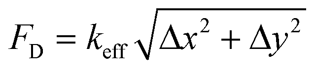 for the cages placed in the diagonal direction. (B) Is a representative contractile force over time curve taken from the EHT while the tissue was spontaneously beating on day 8 (black: longitudinal, red: diagonal). The vertical arrows denote the peak systolic force, horizontal arrows show the duration of the pulse at 80% below the peak (t80). The inset shows a close-up view of the downstroke in which the arrows show 80% of the relaxation duration. (C) Peak force tissues exerted on the attachment sites as the length is increased. (D) Peak forces applied to longitudinal and diagonally placed cages. The data points are shown with means ±1 SD on plots; Student's t test, α = 005. (E) An illustration depicting the simplified force measurement of the EHTs generated in uniaxial configuration. (F) Representative twitch force curves from 0.5 mm, 1 mm, 1.5 mm, and 2 mm long EHTs. (G) Is the comparison of peak systolic forces for 3 different chips at day 8. for the cages placed in the diagonal direction. (B) Is a representative contractile force over time curve taken from the EHT while the tissue was spontaneously beating on day 8 (black: longitudinal, red: diagonal). The vertical arrows denote the peak systolic force, horizontal arrows show the duration of the pulse at 80% below the peak (t80). The inset shows a close-up view of the downstroke in which the arrows show 80% of the relaxation duration. (C) Peak force tissues exerted on the attachment sites as the length is increased. (D) Peak forces applied to longitudinal and diagonally placed cages. The data points are shown with means ±1 SD on plots; Student's t test, α = 005. (E) An illustration depicting the simplified force measurement of the EHTs generated in uniaxial configuration. (F) Representative twitch force curves from 0.5 mm, 1 mm, 1.5 mm, and 2 mm long EHTs. (G) Is the comparison of peak systolic forces for 3 different chips at day 8. | ||
Fig. 6B displays the contractile forces of the spontaneous beating tissue acting on the attachment sites. Interestingly, we observed that the forces on the diagonal cages were noticeably higher than the forces on the cages that were placed in the longitudinal direction for this particular tissue. Contraction and relaxation times measured from the diagonal cages were about the same (Fig. 6B, inset). Fig. 6C shows the peak twitch forces generated by stadium-like EHTs across tissues with different lengths (0.8 mm, 1 mm, 1.2 mm, 1.4 mm) and aspect ratios (1.6, 2, 2.4, 2.8), where we used each attachment site as a probe. Here, there wasn't a significant difference in the twitch forces between 0.8 mm and 1 mm, but the increase in the force as a function of length became prominent as the length was further increased. In Fig. 6D we further explore this data using FD and FL. As we scale the tissues in length, the average peak force exerted upon the 0° attachment sites increased only slightly. The forces reported from the diagonal cages, however, had a ∼3-fold increase from levels of 50 μN to levels >150 μN. When we further analyzed the displacements we observed in x and y directions, we observed that the assumption we made in simulating the spring constant (Fx = Fy due to 45°) breaks down for 1.2 mm and 1.4 mm long tissues (see Fig. S5†). Regardless, there is a clear improvement in force output as we scale the tissues, which can be due to two main reasons. First, we expect the number of cells within the tissue to scale linearly with the increase in length (see Table 1), due to our seeding methodology. Second, we could be observing the force-length relationship in muscle contraction.32,33
Myofibrils appear to be more aligned at the edges than at the centers, and they appear to keep this tangential alignment as we increase the aspect ratio of the EHTs (see Fig. S6 and S7†). This could explain why the force output is improved substantially at the diagonal attachment sites, whereas the deflections measured from 0° cages are probably due more to the muscle fibers at the center of the tissues. As we increase the length of the EHTs, the fiber alignment at the core seems to remain random, which prevents the longitudinal alignment across the entire length of the tissues for both short and long EHTs. This might explain why the increase in length doesn't significantly affect the contractile force exerted on the cages placed in the longitudinal direction. Overall, our approach allows for the measurement and comparison of local twitch forces, and in this case, it revealed heterogeneous contractile dynamics inside the 1.2 mm and 1.4 mm long EHTs. Now we turn to the analysis of the spontaneous contractions for the uniaxial EHTs generated in rectangular cavities, which are illustrated in Fig. 6E. Fig. 6F shows an example of spontaneous twitch forces generated at various lengths over the course of 10 seconds for these types of EHTs. Similar to before, we can extract some metrics regarding the contractile behavior of the tissues with different lengths. Fig. 6G displays the peak forces at day 8, which were measured by tracking and averaging the deflection of triplets of attachment sites at both sides. The comparison across the EHTs generated in 3 different chips reveals a significant difference in peak systolic forces between 0.5 mm and 1 mm long tissues, where the latter causes larger deflections of the cages. Although there was some chip-to-chip irregularity in the peak values of twitch forces, the overall trend looks similar. There appears to be a modest increase when the tissue is further scaled to 1.5 mm. Surprisingly, we did not observe a prominent increase in the force when the EHTs were scaled to 2 mm. We observed a similar trend when we tested tissues generated from the second hiPSC line (GSB-L550) on another chip (see Fig. S8 and Movie S4†).
During the optimization process of tailor-made rectangular seeding wells, we doubled the length of cages and increased the surface area, particularly for 1.5 mm and 2 mm long cavities. This provided a more robust interface between the EHTs and the cages, preventing detachment and enabling the generation of longer EHTs. We chose a 1 mm length to also test and compare the effect of doubling the length of the attachment sites. DLW thus allowed us to study the effects of asymmetry and architecture of mechanical constraints upon uniaxially contracting EHTs,34 in addition to length. Briefly, we typically observed higher contractile force output from the longer attachment sites. Details of this investigation can be found in ESI† (see Fig. S10).
Our platform is also compatible with electrical stimulation systems and protocols, which are shown to enhance alignment, functionality, and maturation of the EHTs.35,36 We used a protocol that ramps up the frequency of pacing to assess the contractile performance of EHTs at physiologically relevant beat rates. Fig. 7A shows a representative trace of tissue contractions taken from a 1.2 mm long EHT (Fig. 7A, inset) during the application of this protocol on day 9. We start by recording the spontaneous contractions without any stimulation. After about 20 seconds, we initiate the protocol, which applies biphasic electrical pulses periodically for 20 seconds, sequentially at 0.5 Hz, 1 Hz, 1.5 Hz, 2 Hz, and 2.5 Hz, followed by a restart of the protocol at 0.5 Hz. The blue curve here represents instantaneous contraction frequencies for this example, calculated as the inverse of interbeat intervals. All EHTs showed a similar trend in terms of beating frequency. They were all able to adapt and keep up with the stimulation frequency with minor fluctuations, but the contractile forces exerted on the cage microstructures changed as a function of frequency.
 | ||
| Fig. 7 Frequency-dependent contractile behavior of the EHTs generated in stadium-like seeding wells. (A) A force over time recording generated by tracking and averaging the displacements of the 0° oriented cages of a 1.2 mm long tissue (L/W ≈ 24) during electrical stimulation protocol. The tissues were stimulated at 0.5 Hz, 1 Hz, 1.5 Hz, 2 Hz, 2.5 Hz, and back to the 0.5 Hz (blue curve) starting from 20 seconds. (B) Is from the same tissue, but the force is plotted based on tracking and averaging the displacements of all diagonal cages. (C) Contraction durations (t80) of 0.8 mm long and 1.4 mm long tissues during the electrical stimulation regimen. (D) The temporal evolution of maximum contractile forces for 0.8 mm, 1 mm, 1.2 mm, and 1.4 mm long tissues. (E) Contraction durations at half maximum (t50) of tissues with different lengths, as a function of the excitation frequency. In (D) and (E) a 0° oriented cage placed in the longitudinal direction was analyzed for all EHTs. (F) Spontaneous frequencies of the tissues before initiation of the stimulation protocol. | ||
The change in force has two components: (1) the purely active component of the contractile oscillations, and (2) the baseline deflections, which give information about quasi-static tension. We observed a decrease in active twitch forces as the stimulation frequency was increased for all the EHTs generated in stadium-like configuration. However, we again observed a few differences between the contractile motion of cages placed in lengthwise and diagonal orientations. In Fig. 7B, for the 1.2 mm long tissue, averaged contractile behavior from diagonal attachment sites indicates that the quasistatic tension (baseline) increases with stimulation frequency at the corners of the tissue. However, we did not observe this behavior on the cages that are placed in the longitudinal direction. Another example is given in Fig. S9 using a longer (1.4 mm) tissue. There, quasistatic tension increases for diagonal cages along with an additional force increase, consistent with what we observed for spontaneous contractions (Fig. 6D). Overall, the baseline increase in these traces suggests that the EHTs or the platform itself do not have time to fully relax at the corners at higher frequencies. Nonetheless, the tissue is still able to apply a considerable force in this condition. In Fig. 7C, we give another example of the difference in temporal dynamics measured from longitudinally- and diagonally-placed cages. The twitch duration, measured and averaged (n = 2 for 0°, n = 4 for diagonal) from cages in both orientations, reveals a decrease as a function of frequency for 0.8 mm long and 1.4 mm long tissues.
Next, the peak forces exerted on a single longitudinal cage over the course of this test were estimated and compared between the EHTs that were scaled in the direction of contraction (see Fig. 7D). Overall, we observed transient drops each time the frequency is ramped by 0.5 Hz increments. Afterward, the tissues appeared to adapt to the stimulation frequency and increase the force output. In Fig. 7E, we compared the half of contraction durations (t50) between these cardiac EHTs as the stimulation frequency is ramped up. All of these tissues show a decrease in contraction duration, which could be due to faster beat dynamics correlated with faster calcium signaling,37 or it could be due to insufficient time for relaxation at higher frequencies.38
We also performed a frequency-dependent contractile analysis of the uniaxial EHTs by implementing the same electrical pacing protocol on day 9. Fig. 8 summarizes some of our findings. Contractile traces of 0.5 mm long and 1 mm long tissues over the course of the experiment are shown in Fig. 8A. Unlike all other tissues, the 0.5 mm long tissue did not beat spontaneously, but we were still able to stimulate and entrain this EHT up to 2.5 Hz, with minor deviations in beat frequencies. The total force exerted on the triplets of cages due to contractions increased as a function of frequency. There was a major increase in the forces exerted upon the attachment sites when the tissue was scaled to 1 mm and above. This could be due to (1) the higher number of cells that were centrifuged into the larger cavities, (2) the increased tension at the edges, and/or (3) the increased surface area in proportion to the attachment sites that are doubled in length. Fig. 8C and D present the contraction durations t80 and t50 respectively. In these plots, it is evident that the shortest and smallest tissue has the fastest temporal dynamics. Interestingly, it was also the only tissue with a psuedo-positive force-frequency response and without spontaneous contractions. Fig. 8E reports the spontaneous beating frequencies of these EHTs before the experiment (except the quiescent 0.5 mm long EHT).
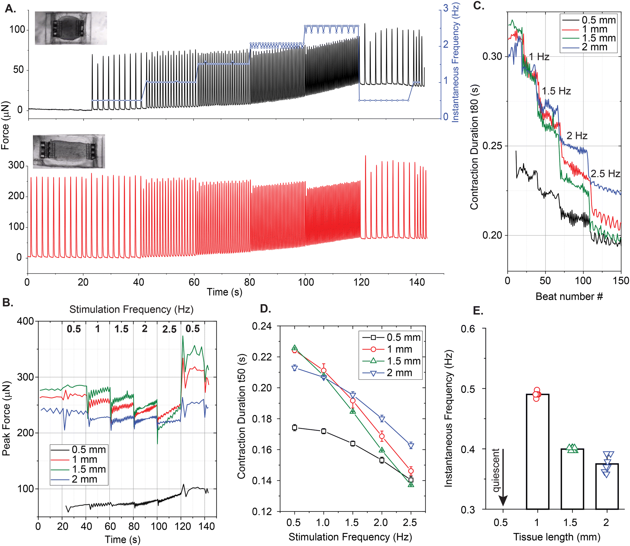 | ||
| Fig. 8 Frequency dependent analysis of contractile behavior of EHTs generated in rectangular cavities. (A) A representative force over time curves during electrical stimulation for 0.5 mm and 1 mm long EHTs with aspect ratios L/W ≈ 125 and L/W ≈ 3. Insets show brightfield images of these EHTs. The blue curve denotes the instantaneous beating frequencies of an EHT before and during the ramp test. (B) The temporal evolution of peak contractile forces and (C) contraction durations (t80) for 0.5 mm, 1 mm, 1.5 mm, and 2 mm long tissues over the course of the test. (D) Contraction durations of tissues with different lengths (t50) as a function of the excitation frequency. (E) Spontaneous frequencies of the tissues before the initiation of stimulation protocol, where the 0.5 mm long tissue was quiescent. | ||
4 Discussion
It is instructive to compare some of the structural and functional metrics of the tissues generated in this study with each other and the literature. To do this, it is helpful to revisit Table 1 for the estimated properties of the tailor-made seeding wells and the heart tissues that are engineered within them. For the first iteration, which used a stiff cavity and a lower density of cardiac cells per tissue, we observed an improvement in fiber alignment as the tissues were scaled up. However, the tissues were unstable, likely due to extreme tension. Next, our versatile fabrication technique allowed us to rapidly optimize the design via direct laser writing of a mold that generates taller and softer seeding wells, and longer mechanical boundaries that provide more surface area for tissues to prevent rupture or stiction during remodeling. Unlike the platforms that only use elastomer pillars, we didn't have issues such as V-neck formation right next to the boundaries17 or movement of the tissues over time in the vertical direction.39 The tissues generated in the softer cavities with a higher density of cells, more collagen collected by the cavity, and elongated attachment sites for longer designs, were quickly stabilized. Nevertheless, the fiber alignment in these tissues was not as pronounced as in the previous iteration, and did not necessarily improve with increased aspect ratio. Particularly at the center, there seemed to be thickening (∼100 μm for the bottom half of the EHT) due to the higher number of cells. The diameter of the cages was ∼100 μm, this can be enlarged by 1.5× to potentially achieve a more homogeneous thickness distribution for the generated tissues in the future.It is possible to compare the performance of EHTs in stadium-like seeding wells with 6 attachment sites, and the ones in rectangular cavities with 2 effective attachment sites. The approximate number of cells, for example, are (see Table 1) ∼80000–118000 for the 1–1.4 mm long tissues generated in soft stadium-like cavities. These numbers are 75000–111000 for the 1 mm and 1.5 mm long uniaxially contracting EHTs, so it might be reasonable to compare these tissues. The contractile forces exerted upon triplet cage complexes are 2–3× more in the rectangular EHTs than the forces reported from the cages on the hemicylindrical membranes. Since this could be due to the forces concentrated on two mechanical boundaries instead of six, it is more reasonable to multiply the forces reported for the tissues suspended between hemicylindrical membranes by 3× for comparison, which yields contractile forces of the same order. The diagonal cages also enabled us to measure active tangential forces. Here, we observed an improvement as EHTs were scaled in length.
Our platform also allowed us to investigate the calcium dynamics of the tissues (see Movie S5 and Fig. S11†). Calcium handling of the EHTs generated in our platform appears to have very similar temporal qualities and frequency dependence to some of the state-of-the-art EHTs in the literature.10 Furthermore, the tissues were able to keep up with 5 Hz stimulation frequency, significantly above a healthy adult human heart rate. The amplitude of these oscillations, on the other hand, does not increase as a function of frequency, which indicates the immature state of the EHTs generated in this study.36,40 Although a larger sample size for each tissue length and geometric configuration is needed to make more rigorous and reliable comparisons, we have demonstrated that the platform enables the generation, scaling, and assessment of EHTs in different mechanical environments. Our approach using DLW allowed us to rapidly overcome the obstacles by providing necessary mechanical cues to the cells. Furthermore, it allowed us to investigate asymmetric configurations (Fig. 4 and ESI†) and local forces on different regions of the EHTs.
5 Conclusion and future work
In this work, we further optimized the mechanical and geometric properties of the platform we presented before21 to generate, study, and compare EHTs at various geometric configurations and lengths. One of our key contributions is using what we learned about the interplay between fiber alignment and tissue stability to improve the stability through control of geometry and mechanical properties of the seeding wells, along with the seeding parameters. Our investigations of contractile motion and observation of heterogeneous behavior inside some of EHTs elucidate how myofibril structure affects the local contractions. We also show the compatibility of the platform with electrical stimulation and calcium imaging studies by investigating the functioning of EHTs at various stimulation frequencies.Since this work only focused on the mechanical and geometric aspects of optimization for the generation of EHTs, other bioengineering methods can be expected to drive further improvement and maturation of the EHTs. For instance, fibrin can be used as a hydrogel instead of collagen, or ventricular cardiac fibroblasts can be used as stromal cells rather than hMSCs to potentially improve the fiber and cell alignment.10 Longer-term electrical pacing regimens can be applied in our platform for the maturation of the EHTs generated in this study. Microfluidic channels can be incorporated to provide dynamic stretching21,29 (see microfluidic channels in Fig. 1C), or they can be adapted for cyclic or continuous perfusion of the media.41,42 DLW can be utilized further to engineer EHTs themselves as a cardiac pump.43 Incorporation of such methods would allow the modeling of various diseases or pharmacological testing on mature tissues. The EHTs with the optimum size and geometry can also be scaled in number and subsequently harvested for bioprinting a larger cardiac patch,44,39 which could eventually replace the diseased tissue in patients with myocardial infarction.
Author contributions
M. Ç. K., J. E., C. S. C., A. E. W., and K. L. E. conceived the project. M. Ç. K. designed and M. Ç. K. and A. S. fabricated the platform. J. K. E. and M. C. W. differentiated human iPS cells, J. K. E. and M. Ç. K. generated the engineered heart tissues. M. Ç. K. developed the finite element model. M. Ç. K., J. K. E., and A. S. conducted the experiments and collected data. S. S. provided the analysis software to estimate contractile dynamics, M. Ç. K. and A. S. performed the analysis. All authors interpreted data; M. Ç. K., J. E., S. S., A. E. W., and K. L. E. wrote the manuscript.Conflicts of interest
The authors declare that the research was conducted in the absence of any commercial or financial relationships that could be construed as a potential conflict of interest.Acknowledgements
This work was supported by NSF CELL-MET ERC award no. EEC-1647837, and National Institute of Health National Heart Lung and Blood grant F31 HL158195-03 (J. K. E.). Research reported in this publication was also supported by the BU Photonics Center, the Boston University Micro and Nano Imaging Facility and the Office of the Director of the National Institutes of Health under award Number S10OD024993. The content is solely the responsibility of the authors and does not necessarily represent the official views of the National Institute of Health. The authors would like to thank Rachael Jayne, Christos Michas, Hiba Kobeissi, and Emma Lejeune for their contributions that did not make it into the final work, and for useful discussions. The authors would like to thank the Seidman Lab for kindly sharing their iPSC cell lines, and Xining Gao for her help with the maintenance of the engineered heart tissues.References
- E. Ehler, Biochim. Biophys. Acta, Mol. Cell Res., 2016, 1863, 1857–1863 CrossRef CAS PubMed.
- J. Zhang, G. F. Wilson, A. G. Soerens, C. H. Koonce, J. Yu, S. P. Palecek, J. A. Thomson and T. J. Kamp, Circ. Res., 2009, 104, e30–e41 CAS.
- A. J. Ribeiro, Y.-S. Ang, J.-D. Fu, R. N. Rivas, T. M. Mohamed, G. C. Higgs, D. Srivastava and B. L. Pruitt, Proc. Natl. Acad. Sci., 2015, 112, 12705–12710 CrossRef CAS PubMed.
- N. Silbernagel, A. Körner, J. Balitzki, M. Jaggy, S. Bertels, B. Richter, M. Hippler, A. Hellwig, M. Hecker and M. Bastmeyer, et al. , Biomaterials, 2020, 227, 119551 CrossRef CAS PubMed.
- T. Eschenhagen, C. Fink, U. Remmers, H. Scholz, J. Wattchow, J. Weil, W. Zimmermann, H. H. Dohmen, H. Schäfer and N. Bishopric, et al. , FASEB J., 1997, 11, 683–694 CrossRef CAS PubMed.
- W. H. Zimmermann, K. Schneiderbanger, P. Schubert, M. Didié, F. Münzel, J. F. Heubach, S. Kostin, W. L. Neuhuber and T. Eschenhagen, Circ. Res., 2002, 90, 223–230 CrossRef CAS PubMed.
- T. Eschenhagen and W. H. Zimmermann, Circ. Res., 2005, 97, 1220–1231 CrossRef CAS PubMed.
- W. R. Legant, A. Pathak, M. T. Yang, V. S. Deshpande, R. M. McMeeking and C. S. Chen, Proc. Natl. Acad. Sci. U. S. A., 2009, 106, 10097–10102 CrossRef CAS PubMed.
- T. Boudou, W. R. Legant, A. Mu, M. A. Borochin, N. Thavandiran, M. Radisic, P. W. Zandstra, J. A. Epstein, K. B. Margulies and C. S. Chen, Tissue Eng., Part A, 2012, 18, 910–919 CrossRef CAS PubMed.
- M. A. Tamargo, T. R. Nash, S. Fleischer, Y. Kim, O. F. Vila, K. Yeager, M. Summers, Y. Zhao, R. Lock and M. Chavez, et al. , ACS Biomater. Sci. Eng., 2021, 7, 5215–5229 CrossRef CAS PubMed.
- S. S. Nunes, J. W. Miklas, J. Liu, R. Aschar-Sobbi, Y. Xiao, B. Zhang, J. Jiang, S. Massé, M. Gagliardi and A. Hsieh, et al. , Nat. Methods, 2013, 10, 781 CrossRef CAS PubMed.
- E. Y. Wang, N. Rafatian, Y. Zhao, A. Lee, B. F. L. Lai, R. X. Lu, D. Jekic, L. Davenport Huyer, E. J. Knee-Walden and S. Bhattacharya, et al. , ACS Cent. Sci., 2019, 5, 1146–1158 CrossRef CAS PubMed.
- N. Thavandiran, N. Dubois, A. Mikryukov, S. Massé, B. Beca, C. A. Simmons, V. S. Deshpande, J. P. McGarry, C. S. Chen and K. Nanthakumar, et al. , Proc. Natl. Acad. Sci., 2013, 110, E4698–E4707 CrossRef CAS PubMed.
- W. Bian, C. P. Jackman and N. Bursac, Biofabrication, 2014, 6, 024109 CrossRef CAS PubMed.
- E. Querdel, M. Reinsch, L. Castro, D. Köse, A. Bähr, S. Reich, B. Geertz, B. Ulmer, M. Schulze and M. D. Lemoine, et al. , Circulation, 2021, 143, 1991–2006 CrossRef CAS PubMed.
- H. Wang, A. A. Svoronos, T. Boudou, M. S. Sakar, J. Y. Schell, J. R. Morgan, C. S. Chen and V. B. Shenoy, Proc. Natl. Acad. Sci., 2013, 110, 20923–20928 CrossRef CAS PubMed.
- O. J. Abilez, E. Tzatzalos, H. Yang, M.-T. Zhao, G. Jung, A. M. Zöllner, M. Tiburcy, J. Riegler, E. Matsa and P. Shukla, et al. , Stem Cells, 2018, 36, 265–277 CrossRef CAS PubMed.
- A. P. Petersen, N. Cho, D. M. Lyra-Leite, J. W. Santoso, D. Gupta, N. R. Ariyasinghe and M. L. McCain, Integr. Biol., 2020, 12, 34–46 CrossRef PubMed.
- T. Nakane, H. Masumoto, J. P. Tinney, F. Yuan, W. J. Kowalski, F. Ye, A. J. LeBlanc, R. Sakata, J. K. Yamashita and B. B. Keller, Sci. Rep., 2017, 7, 45641 CrossRef CAS PubMed.
- N. Thavandiran, C. Hale, P. Blit, M. L. Sandberg, M. E. McElvain, M. Gagliardi, B. Sun, A. Witty, G. Graham and V. T. Do, et al. , Sci. Rep., 2020, 10, 1–13 CrossRef PubMed.
- R. K. Jayne, M. Ç. Karakan, K. Zhang, N. Pierce, C. Michas, D. J. Bishop, C. S. Chen, K. L. Ekinci and A. E. White, Lab Chip, 2021, 21, 1724–1737 RSC.
- I. Johnston, D. McCluskey, C. Tan and M. Tracey, J. Micromech. Microeng., 2014, 24, 035017 CrossRef CAS.
- R. K. Jayne, T. J. Stark, J. B. Reeves, D. J. Bishop and A. E. White, Adv. Mater. Technol., 2018, 3, 1700293 CrossRef.
- S. Dogru, B. Aksoy, H. Bayraktar and B. E. Alaca, Polym. Test., 2018, 69, 375–384 CrossRef CAS.
- A. Sharma, C. N. Toepfer, T. Ward, L. Wasson, R. Agarwal, D. A. Conner, J. H. Hu and C. E. Seidman, Curr. Protoc. Hum. Genet., 2018, 96, 21.11.1–21.11.20 CAS.
- L. Liu, S. P. Shenoy, J. W. Jahng, Y. Liu, J. W. Knowles, Y. Zhuge and J. C. Wu, Stem Cell Res., 2021, 53, 102279 CrossRef CAS PubMed.
- L. Sala, B. J. Van Meer, L. G. Tertoolen, J. Bakkers, M. Bellin, R. P. Davis, C. Denning, M. A. Dieben, T. Eschenhagen and E. Giacomelli, et al. , Circ. Res., 2018, 122, e5–e16 CrossRef CAS PubMed.
- C. Pasqualin, F. Gannier, A. Yu, D. Benoist, I. Findlay, R. Bordy, P. Bredeloux and V. Maupoil, J. Imaging, 2022, 8, 95 CrossRef PubMed.
- H. Kobeissi, J. Jilberto, M. Ç. Karakan, X. Gao, S. J. DePalma, S. L. Das, L. Quach, J. Urquia, B. M. Baker and C. S. Chen, et al., arXiv, 2023, preprint, arXiv:2308.04610, DOI:10.48550/arxiv.2308.04610.
- P. Bose, J. Eyckmans, T. D. Nguyen, C. S. Chen and D. H. Reich, ACS Biomater. Sci. Eng., 2018, 5, 3843–3855 CrossRef PubMed.
- Y. Li, H. Asfour and N. Bursac, Acta Biomater., 2017, 55, 120–130 CrossRef CAS PubMed.
- I. C. Turnbull, I. Karakikes, G. W. Serrao, P. Backeris, J.-J. Lee, C. Xie, G. Senyei, R. E. Gordon, R. A. Li and F. G. Akar, et al. , FASEB J., 2014, 28, 644 CrossRef CAS PubMed.
- C. F. Asnes, J. P. Marquez, E. L. Elson and T. Wakatsuki, Biophys. J., 2006, 91, 1800–1810 CrossRef CAS PubMed.
- C. Wang, S. Koo, M. Park, Z. Vangelatos, P. Hoang, B. R. Conklin, C. P. Grigoropoulos, K. E. Healy and Z. Ma, Adv. Healthcare Mater., 2020, 9, 1901373 CrossRef CAS PubMed.
- M. Radisic, H. Park, H. Shing, T. Consi, F. J. Schoen, R. Langer, L. E. Freed and G. Vunjak-Novakovic, Proc. Natl. Acad. Sci., 2004, 101, 18129–18134 CrossRef CAS PubMed.
- K. Ronaldson-Bouchard, S. P. Ma, K. Yeager, T. Chen, L. Song, D. Sirabella, K. Morikawa, D. Teles, M. Yazawa and G. Vunjak-Novakovic, Nature, 2018, 556, 239–243 CrossRef CAS PubMed.
- U. Saleem, I. Mannhardt, I. Braren, C. Denning, T. Eschenhagen and A. Hansen, Stem Cell Rep., 2020, 14, 312–324 CrossRef CAS PubMed.
- I. Mannhardt, K. Breckwoldt, D. Letuffe-Brenière, S. Schaaf, H. Schulz, C. Neuber, A. Benzin, T. Werner, A. Eder, T. Schulze, B. Klampe, T. Christ, M. N. Hirt, N. Huebner, A. Moretti, T. Eschenhagen and A. Hansen, Stem Cell Rep., 2016, 7, 29–42 CrossRef CAS PubMed.
- J. H. Ahrens, S. G. Uzel, M. Skylar-Scott, M. M. Mata, A. Lu, K. T. Kroll and J. A. Lewis, Adv. Mater., 2022, 2200217 CrossRef CAS PubMed.
- A. F. Godier-Furnémont, M. Tiburcy, E. Wagner, M. Dewenter, S. Lämmle, A. El-Armouche, S. E. Lehnart, G. Vunjak-Novakovic and W.-H. Zimmermann, Biomaterials, 2015, 60, 82–91 CrossRef PubMed.
- C. P. Jackman, A. L. Carlson and N. Bursac, Biomaterials, 2016, 111, 66–79 CrossRef CAS PubMed.
- N. Huebsch, B. Charrez, G. Neiman, B. Siemons, S. C. Boggess, S. Wall, V. Charwat, K. H. Jæger, D. Cleres and Å. Telle, et al. , Nat. Biomed. Eng., 2022, 6, 372–388 CrossRef CAS PubMed.
- C. Michas, M. Ç. Karakan, P. Nautiyal, J. G. Seidman, C. E. Seidman, A. Agarwal, K. Ekinci, J. Eyckmans, A. E. White and C. S. Chen, Sci. Adv., 2022, 8, eabm3791 CrossRef PubMed.
- F. Weinberger, I. Mannhardt and T. Eschenhagen, Circ. Res., 2017, 120, 1487–1500 CrossRef CAS PubMed.
Footnote |
| † Electronic supplementary information (ESI) available. See DOI: https://doi.org/10.1039/d3lc00752a |
| This journal is © The Royal Society of Chemistry 2024 |