DOI:
10.1039/D3JA00168G
(Technical Note)
J. Anal. At. Spectrom., 2024,
39, 76-85
Evaluations of the optimal plasma treated area in total reflection X-ray fluorescence analysis and the retention period of superhydrophilic ability of the substrate
Received
25th May 2023
, Accepted 2nd November 2023
First published on 20th November 2023
Abstract
Total reflection X-ray fluorescence (TXRF) analysis is used to determine the concentrations of trace elements in liquid samples. Solutions are generally added dropwise onto a flat substrate and dried. When liquids with low elemental levels are analyzed, a hydrophobic substrate is employed to prepare a small dome-shaped residue. In the analyses of high-level solutions (high elemental concentration solution), the quantitative accuracy and measurement sensitivity deteriorate because X-ray fluorescence (XRF) is absorbed inside the thick residue. By preparing a thin residue, it is possible to reduce this absorption effect. In our previous study, atmospheric pressure plasma jet (APPJ) treatment was used to prepare a superhydrophilic substrate. The time that super-hydrophilicity is maintained is not yet known and determining this value is important for performing TXRF analysis. Therefore, we measured the contact angles of the droplets and performed X-ray photoelectron spectroscopy of the substrate surfaces to determine the relationships between the experimental values and the elapsed time. The optimal APPJ-treated area has not yet been determined and is one of the most important factors for high-sensitivity analysis. In this study, we controlled the APPJ-treated area by preparing four polytetrafluoroethylene (PTFE) masks with different hole diameters and obtained recoveries, relative standard deviations, and minimum detection limits (MDLs) to identify the optimal APPJ-treated area. A PTFE mask with a diameter of 4 mm generated the best values, particularly for low-Z elements. By controlling the diameter of the dried residue to 4 mm, the MDL value in aluminum was improved by a factor of 1.7.
1. Introduction
Total reflection X-ray fluorescence (TXRF) analysis1 is used to determine the concentrations of trace elements in liquid samples such as wastewater,2 rainwater,3 and human blood.4 In X-ray fluorescence (XRF) analysis, an X-ray beam is irradiated onto a sample, the emitted XRF is collected by a detector, and qualitative and quantitative analyses are performed. In this method, X-rays are generally irradiated at an angle of 45° to the sample and XRF is observed at an angle of 45° to the sample. The incident X-ray beam travels through the sample and the averaged elemental information is obtained. However, scattered X-rays, generated by the interaction of X-rays with electrons in the sample, are observed as a background (BG) intensity in the XRF spectrum. In TXRF analysis, an X-ray beam irradiates the sample at a very small glancing angle (90° – incident angle), and the total reflection phenomenon of X-rays is caused at the sample surface, resulting in the minimal generation of scattered X-rays. The glancing angle must be set to less than the critical angle and the critical angle depends on the X-ray beam energy and sample density. For example, a previous study showed that when an X-ray beam of 17.48 keV irradiated a silicon sample, the critical angle was 0.1° (1.75 mrad).5 Detectors such as a SiPIN detector and a silicon drift detector (SDD) were placed directly above the sample and emitted XRF was observed. TXRF analysis is highly sensitive and involves a liquid sample that is generally added dropwise onto a substrate with a flat surface and then dried. Quartz glass and glass slides are used as sample holders. Generally, a hydrophobic substrate is prepared to form dotted-type residues,6,7 which improve the XRF detection efficiency. When measuring samples with low concentrations of elemental impurities, or when the XRF energy of the target element is high, the use of a hydrophobic substrate is beneficial.
However, because XRF is absorbed in the dotted-type residues, we conclude that the formation of dotted-type residues is not recommended when the matrix concentration in the solvent is high or the XRF energy is low. The absorption effect of XRF follows the Lambert–Beer law; therefore, high-sensitivity TXRF analysis can be performed when a thin-film-type residue is prepared. Sample preparations using resist patterns, carbon evaporation, and freeze-drying techniques have been reported to solve this problem.8–10
We used superhydrophilic substrates treated with an atmospheric pressure plasma jet (APPJ) to improve the analytical accuracy of TXRF measurements.11 APPJ is used for surface modification in the semiconductor and medical industries.12,13 Quartz glass contains silanol groups (Si–OH), which are hydrophilic, owing to the hydroxy group. When a solution was added dropwise onto a sample holder consisting of quartz glass with a clear surface exposed to hydroxy groups, it resulted in the solution being widely spread. However, hydroxy groups are bound to polar organic molecules that are present in air by hydrogen bonds. The binding between polar organic molecules bound to hydroxy groups and non-polar organic molecules is facilitated by intermolecular forces;14 therefore, quartz glass exposed to air is typically not completely hydrophilic. Because these bonds are weak, APPJ treatment can remove organic molecules from quartz glass. As a result, we have previously succeeded in preparing a wide dried residue using APPJ-treated quartz glass.11 Generally, argon plasma that forms the streamer discharge is used, while a helium plasma forms the glow discharge. Therefore, the number of charge particles in a plasma is small; as a result, the heat generated by irradiating the plasma will not be almost affected. This method is useful for improving the measurement accuracy of TXRF analysis; however, the conditions required have not yet been optimized. In a previous study, a polytetrafluoroethylene (PTFE) mask with an 8 mm hole was placed on the substrate to limit the APPJ-treated area. The effective area of the detector equipped with the TXRF instrument was 50 mm2, which was equivalent to the area of the dried residue. A ring-type residue was prepared from a red wine sample and we determined that the elemental concentration outside the dried residue was higher than that inside.11 This demonstrates the difficulty in sensitively detecting the XRF emitted from the edge of the residue. We have not yet evaluated the size of the dried residue, to determine an optimal size for highly sensitive and accurate TXRF analysis.
Various commercially available TXRF instruments have been developed; therefore, it is important to determine the analysis area for each TXRF instrument. We have previously determined the analytical area measured using a NANOHUNTER-II TXRF instrument (Rigaku Co., Japan) to be approximately 4 × 5 mm2;15 therefore, we believe that the optimal APPJ-treated area should be smaller than this value. In addition, it is important to evaluate the retention time of hydrophilicity after APPJ treatment. In this study, various PTFE masks with one hole of different diameters were prepared and these were used to optimize the APPJ-treated area. To evaluate the retention time after APPJ treatment, we determined the relationship between the elapsed time and the results of contact angle or X-ray photoelectron spectroscopy (XPS) measurement.
2. Experimental
2.1 Chemicals
For TXRF analysis, an internal standard method was used to determine the trace elements in the sample solutions. A gallium (Ga) standard solution was purchased from AccuStandard Inc. (New Haven, CT, USA). To evaluate the developed method, multi-element standard solution L-1 and potassium (K), magnesium (Mg) and phosphorus (P) standard solutions of 1000 ppm (μg g−1) (FUJIFILM Wako Pure Chemical Corporation, Japan) were prepared. Standard solution L-1 contained aluminum (Al), calcium (Ca) and iron (Fe) at 1000 ppm and Mg, chromium (Cr), barium (Ba), lead (Pb), and strontium (Sr) at 100 ppm. The standard solutions were diluted using ultrapure water (FUJIFILM Wako Pure Chemical Corporation). Quartz glass (Daiko Corporation, Japan) was used as the sample substrate. The glass substrate was cleaned using 60% nitric acid solution (FUJIFILM Wako Pure Chemical Corporation). A silicone solution (Serva Electrophoresis GmbH, Germany) was used to prepare the hydrophobic substrate.
2.2 Instrumentation
2.2.1 TXRF instrument.
A benchtop NANOHUNTER-II TXRF instrument (Rigaku. Co.) was used to determine the concentration of trace elements in the prepared sample solution. The X-ray tube target was molybdenum (Mo), and the maximum tube voltage and current were 50 kV and 12 mA, respectively. The incident X-ray beam was monochromatized and focused using a multilayer mirror. The incident X-ray beam had two components, Mo Kα (17.48 kV) and high-energy X-rays (approximately 30 keV). The glancing and convergent angles of the primary X-rays were controlled using two movable slits. An SDD with an effective area of 50 mm2 was used to observe the emitted XRF, and the energy resolution was less than 150 eV (Mn Kα: 5.9 keV).
2.2.2 Atmospheric pressure plasma jet.
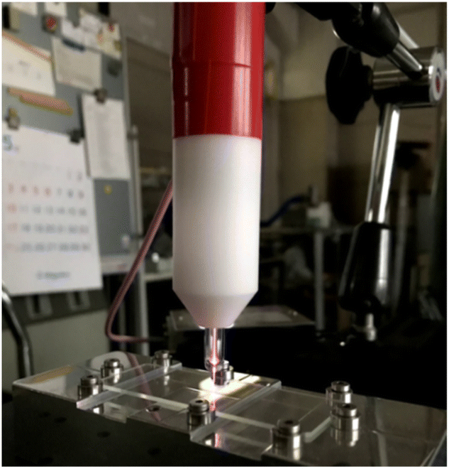
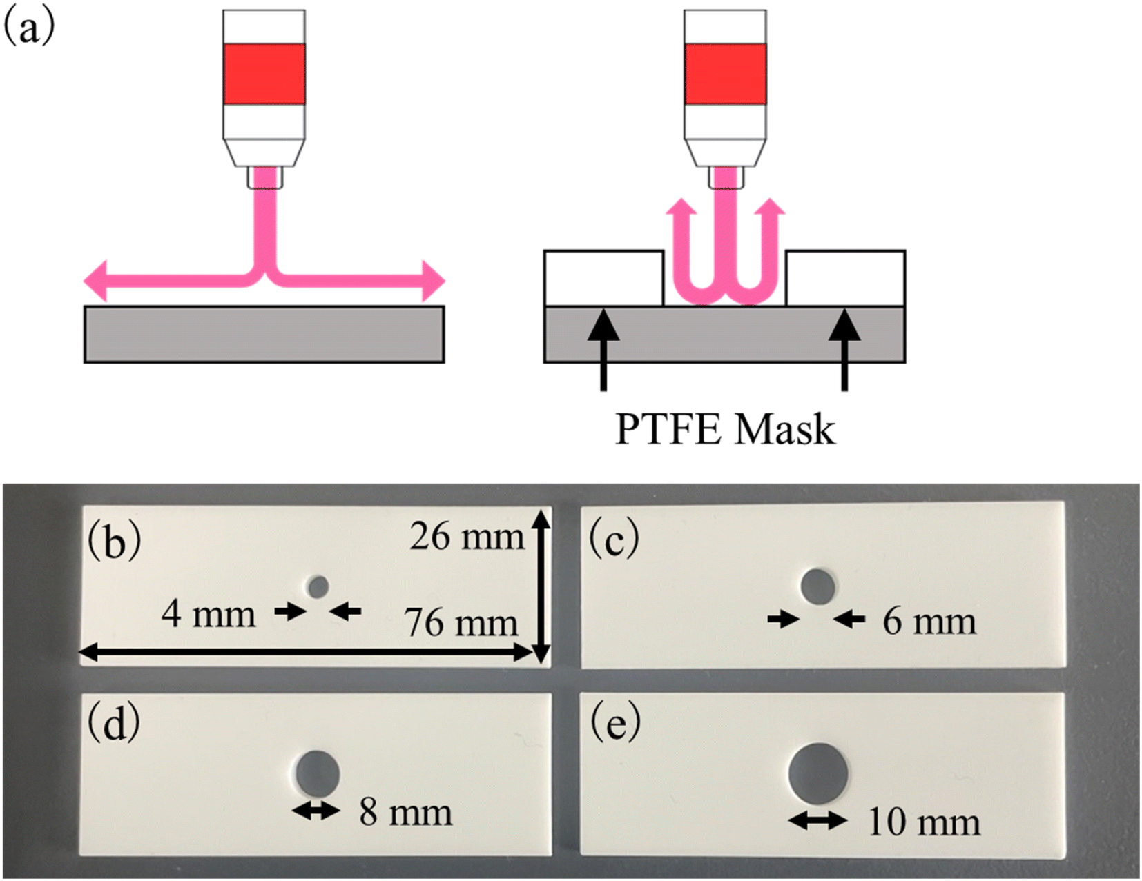
An image of the APPJ device is shown in Fig. 1.16–18 In brief, the APPJ assembly is 150 mm long, with a 4 mm inner diameter and a 6 mm outer diameter soda-lime glass tube that tapers to 650 μm at the nozzle. Helium (He) gas was used as the discharge gas. A sinusoidal high voltage of around 10 kVp–p at a fixed frequency of 33 kHz was applied to a single 15 mm long external ring copper electrode wound onto the glass tube at 50 mm from the nozzle. The plasma jet assembly comprised a single electrode configuration. With this configuration, positive and negative discharges are alternatively and frequently generated. Thus, the alterative discharges promptly interact with ambient humid air and generate highly reactive species such as hydroxy radicals. Eventually, highly reactive species can be delivered onto the quartz glass substrate through laminar gas flow and can be altered the surface.19 As shown in Fig. 2a, when the PTFE mask was not used, large areas of quartz glass were treated with APPJ. Images of the PTFE masks used to limit the irradiation area of the APPJ are shown in Fig. 2b–e. The PTFE mask measured 26 mm × 76 mm, with a thickness of 3 mm and hole diameters of 4, 6, 8, or 10 mm.
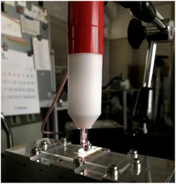 |
| | Fig. 1 Photograph of the APPJ device. The purple part in this figure shows the plasma jet. | |
 |
| | Fig. 2 Schematic diagrams of the APPJ-treated area without (a) and with (b–e) the PTFE mask. Images of PTFE masks with hole diameters of 4, 6, 8, and 10 mm are shown. These masks were used for controlling the APPJ-treated area. | |
2.3 Sample preparations and measurements
2.3.1 Sample preparation for contact angle measurements.
A DMe-211 contact angle meter (Kyowa Interface Science Co., Ltd., Japan)20–22 was used to evaluate the APPJ-treated substrate. The instrument was equipped with a syringe for adding dropwise the aqueous solution, a light source, and a charge-coupled device camera. The outside diameter of the needle was 0.8 mm. To calculate the contact angles of the water droplet, the θ/2 method was used.23 The irradiation time of the APPJ was 1 min, and the distance between the output of the APPJ device and the substrate was 5 mm. A 1 μL aliquot of ultrapure water was added dropwise onto the substrates with and without APPJ treatment and the contact angle of the water droplet was measured after 1 s. We prepared 24 APPJ-treated substrates and obtained the contact angle for each elapsed period: 0, 0.25, 1, 2, 4, 8, and 14 d (N = 4). We compared the contact angle of the APPJ-treated glass substrates with that of the glass substrate cleaned with nitric acid. A 60% nitric acid solution and ultrapure water were mixed in a 1![[thin space (1/6-em)]](https://www.rsc.org/images/entities/char_2009.gif) :1 ratio to prepare a 30% nitric acid solution. The quartz glasses were immersed in the 30% nitric acid solution and cleaned in an ultrasonic bath. The elapsed periods were set to 0, 0.25, 1, 2, 6, and 10 d. The samples were then placed in a desiccator.
:1 ratio to prepare a 30% nitric acid solution. The quartz glasses were immersed in the 30% nitric acid solution and cleaned in an ultrasonic bath. The elapsed periods were set to 0, 0.25, 1, 2, 6, and 10 d. The samples were then placed in a desiccator.
2.3.2 Sample preparation for XPS measurements of quartz glass with APPJ treatment.
To evaluate the surfaces of quartz glass with and without APPJ treatment, an ESCA3400-HSE XPS instrument (Shimadzu Corporation, Japan) with Mg and Al anodes was used.24–26 The maximum tube voltage and current were 12 kV and 30 mA, and a DuPont analyzer was used to obtain the XPS spectra. The chamber was evacuated using rotary and turbo-molecular pumps (10−7 Pa order). Quartz glass with a size of 5 × 5 mm2 was prepared for the XPS measurements. APPJ treatment was performed for 1 min and the flow rate of helium gas was set to 1.5 L min−1. The frequency and voltage of an alternating current were 33 kHz and 10 kV, respectively. Quartz glasses with and without APPJ treatment were analyzed and the XPS spectrum of the elapsed periods 0, 1, 2, 7, and 12 d were obtained. The Mg anode was selected as the target for the X-ray tube, and the tube voltage and current were set to 10 kV and 20 mA, respectively. The step size was 0.1 eV in the XPS spectra. The samples were stored in a desiccator.
2.3.3 Sample preparations for TXRF measurements.
Sample solutions were prepared by mixing 600 μL of ultrapure water, 100 μL of multi-element L-1, 100 μL of K, 100 μL of P, and 100 μL of Ga standard solutions. The final concentration of Al, Ca, Fe, K, and P was 100 ppm and that of Ba, Cr, Mg, Pb, Sr, and Ga, as an internal standard, was 10 ppm. A 10 μL aliquot of the prepared solution was added dropwise onto the silicone and APPJ-treated quartz glasses. The APPJ-treated area was controlled using PTFE masks with hole diameters of 4, 6, 8, or 10 mm. The substrate with the silicone layer was prepared by adding dropwise 50 μL of silicone solution and drying using a dehydrator (FO-45W, Tokyo Garasu Kikai Co., Ltd., Japan) with a drying time of approximately 20 min. Subsequently, a sample droplet on the substrate was dried using a hot plate at 50 °C (N = 4). The prepared residues were measured using a NANOHUNTER-II TXRF instrument. The tube voltage and current were set at 50 kV and 12 mA, respectively, and the measurement time was 600 s. The glancing and convergence angles were 0.025° and 0.05°, respectively.
3. Results and discussion
3.1 Measurements of the contact angle
Fig. 3a shows the result of the elapsed period versus contact angle in the nitric acid cleaned quartz glass substrate. The obtained contact angles are expressed as mean values, and the error bars are standard deviations (SDs). The contact angle for the elapsed period of 0 d was 24.8° ± 4.8°. The contact angle increased as the elapsed period increased until the values remained constant after an elapsed period of 6 d. In addition, the SD values were large. The relative standard deviation (RSD) was defined as: 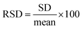 , and expressed as a percentage. The RSDs of the contact angles in the elapsed periods of 0, 0.25, 1, 2, 6, and 10 d were 19.4, 5.80, 6.05, 11.0, 2.13, and 4.47%, respectively. It was observed that the RSD of the contact angle for each elapsed period was unstable.
 |
| | Fig. 3 Relationships between the elapsed period and contact angle without (a) and with (b) APPJ treatment. Quartz glasses were cleaned with nitric acid and the APPJ treatment was then performed. | |
Fig. 3b shows the relationship between the elapsed period and the contact angle in the APPJ-treated samples. The contact angle for the elapsed period of 0 d was 5.23° ± 0.48°. Otitoju et al. defined superhydrophilicity as a contact angle of less than 10°,27 therefore we could prepare a superhydrophilic substrate by APPJ. In the elapsed period of 0.25 d, the contact angle was 16.6° ± 1.6°. The contact angle increased with increasing elapsed time until 14 d and the contact angle was close to the contact angles in the glass substrate cleaned with only nitric acid solution (28.6° ± 1.8°). We consider that the sudden increase in the contact angle in elapsed periods of 0–0.25 d occurred by the binding of the silanol groups with polar organic compounds in the air. Between elapsed periods 0.25–6 d, the polar organic compounds bound to non-polar organic compounds slowly increased the contact angles. In the APPJ treatment, we obtained similar RSD values for the contact angle to that of the nitric acid cleaning experiment. The RSDs of contact angles in elapsed periods 0, 0.25, 1, 2, 4, 8, and 14 d were 9.16, 9.53, 7.42, 1.16, 5.23, 3.48, and 6.40%, respectively. Immediately after the APPJ treatment, the RSD value was lower than that immediately after nitric acid cleaning. The RSD values for the APPJ treatment were stable; therefore, the APPJ treatment resulted in a reproducible dried residue.
3.2 X-ray photoelectron spectroscopy of the APPJ-treated substrate
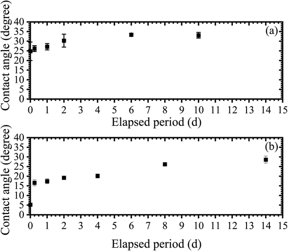
Fig. 4 shows the XPS spectra of quartz glasses without (Fig. 4a) and with (Fig. 4b) APPJ treatment, respectively. In both XPS spectra, O 1s, C 1s, KLL C Auger electrons, Si 2s, and Si 2p peaks were observed. Silicon (Si) and oxygen (O) peaks originated from the silanol groups, and carbon (C) electrons were emitted from organic compounds bound with silanol groups. To obtain the net intensity of XPS peaks, the Shirley method28,29 in the Origin software package was used (LightStone Co., Japan). In the XPS spectrum of quartz glass without APPJ treatment (Fig. 4a) the net intensities for O 1s and C 1s peaks were 1.75 × 10⁶ and 2.90 × 10⁵ cps, respectively, whereas the net intensities for O 1s and C 1s peaks in quartz glass with APPJ treatment were 2.33 × 10⁶ and 1.22 × 10⁵ cps, respectively. Therefore, the APPJ treatment decreased the net intensity of C 1s and increased that of O 1s, showing that the organic molecules bound to silanol groups were removed by APPJ treatment. In addition, we believed that the net intensity of O 1s was increased because the hydroxy groups on the surface were exposed.
 |
| | Fig. 4 XPS spectra of quartz glasses without (a) and with (b) APPJ treatment. | |
Fig. 5 shows the relationship between the elapsed period and relative intensity in the quartz glass with APPJ treatment. The relative intensity was obtained by dividing the net intensity of O 1s with that of C 1s. The relative intensity without APPJ treatment was 6.02 and is shown as a dashed line in Fig. 5. At the elapsed period of 0 d, the relative intensity was 19.1. This was significantly higher than the value without APPJ treatment because the organic molecules on the surface were removed and the hydroxy groups were exposed to the substrate. The relative intensity in elapsed period of 1 d was 8.28, similar to that without APPJ treatment and between the elapsed periods 2–12 d, the relative intensities were constant. Therefore, the relationship between the elapsed period and contact angle (Fig. 3b) was similar to that obtained with APPJ treatment.
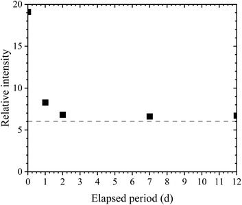 |
| | Fig. 5 Elapsed period versus relative intensity. The relative intensity was obtained by normalizing the O 1s with C 1s net intensities. To separate the net and BG intensities in XPS peaks, the Shirley method was used. | |
3.3 TXRF analysis of trace elements in the multi-element standard solution
3.3.1 Introducing helium gas for measuring low-Z elements.
In the measurement of low-Z elements, the emitted XRF was absorbed into the air between the sample and detector; therefore, when TXRF analyses were performed, the area between the sample and the SDD was filled with He gas. Fig. 6 shows the TXRF spectra with (0.3 L min−1) and without (0.0 L min−1) helium gas. To evaluate an effect of a helium gas flow, an aliquot (10 μL) of Mg solution (100 ppm) prepared by mixing Mg standard solution (1000 ppm) and ultrapure water was added dropwise onto quartz glass, and dried. A clear Ar Kα peak was observed in the spectrum without the He gas and argon (Ar) was present in the air at a concentration of 0.9%. When the flow rate of the helium gas was 0.3 L min−1, an Ar Kα peak was not observed. In addition, the net intensities of Mg Kα peaks with and without helium gas were 0.579 and 2.56 cps, respectively. Therefore, the absorption effect in the XRF peak of low-Z elements, such as Si and Mg, was decreased by the introduction of helium gas. We consider that the flow rate of He gas should be set to 0.3 L min−1, or higher, when TXRF analysis of low-Z elements is performed.
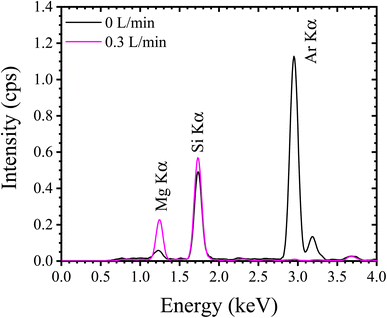 |
| | Fig. 6 Behavior of TXRF spectra by introduction of a helium gas flow. Flow rates of helium gas were set to 0 and 0.3 min L−1. | |
3.3.2 Optimization of TXRF analysis with APPJ treatment.
Fig. 7a shows an image of the dotted-type residue prepared using a hydrophobic substrate with a diameter of 0.7 mm. To control the treatment area, we used PTFE masks with hole diameters of 4, 6, 8, or 10 mm. Fig. 7b–e shows images of the dried residue for each diameter. Film-type residues were prepared using the APPJ-treated substrates. The diameters of the film-type residues in Fig. 7b–e were 4.2, 6.3, 8.4, and 9.9 mm, respectively, which were almost equivalent to the hole sizes of the PTFE masks. The APPJ treatment was performed only inside the hole, which meant that the APPJ did not travel between the PTFE mask and the quartz glass. Therefore, the shape of the dried residue could be controlled by changing the hole diameter in the PTFE mask.
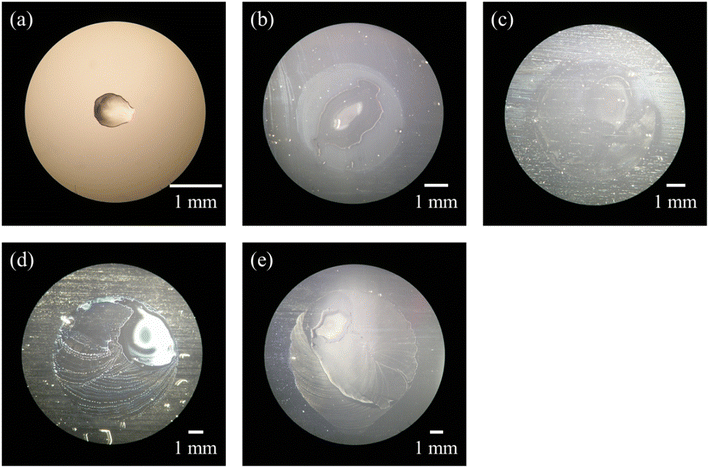 |
| | Fig. 7 Images of the dried residue on quartz glass with a silicone layer (a). (b–e) Dried residue from APPJ-treated quartz glass, using a PTFE mask. Hole diameters were (b) 4 mm, (c) 6 mm, (d) 8 mm, and (e) 10 mm, respectively. | |
Fig. 8a shows the TXRF spectra of the dried residues prepared using silicone-coated and APPJ-treated substrates. Fig. 8b shows an expanded view of the low-intensity area shown in Fig. 8a. Si Kα radiation was observed owing to the quartz glass used as the substrate. Scattering of the incident X-ray beam onto the dried residue or the substrate resulted in the presence of Mo Kα and Compton scattering peaks. Clear XRF peaks for Al, P, K, Ca, Fe, Pb, Sr, and Ga were observed. Table 1 lists the mean values and SDs for the net and BG intensities of the hydrophobic and APPJ-treated substrates (N = 4). For elements other than Sr, the XRF intensities obtained from the film-type residue were higher than those obtained from the dotted-type residues. For example, Al Kα net intensities in substrates coated with the silicone solution or treated with APPJ with a 4 mm diameter mask were 4.24 ± 0.91 and 19.5 ± 0.5 cps, respectively. When TXRF measurement of low-Z elements was performed using a hydrophobic substrate, it was not possible to ignore the absorption effect in the dried residue. We conclude that the absorption effect was reduced by using the APPJ-treated substrate. The XRF intensity of Sr Kα in the hydrophobic substrate (782 ± 158 cps) was higher than that in the APPJ-treated substrate (763 ± 58 cps). The mass attenuation coefficients depend on the XRF energy. The Sr Kα energy (14.14 keV) was higher than that of other elements observed in this spectrum such as K Kα (3.31 keV) and Fe Kα (6.40 keV). This indicates that the absorption effect of the Sr Kα peak in the dried residue was low. Therefore, in the measurement of XRF with high energy, high-sensitivity analysis should be performed by preparing a dotted-type residue on a substrate with a silicone layer.
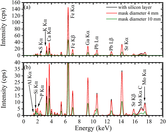 |
| | Fig. 8 (a) TXRF spectra of multi-element standard solution. The PTFE mask with a diameter of 4 or 10 mm was placed on the quartz glass, and then APPJ treatments were performed. As a comparison, a hydrophobic substrate with a silicone layer was prepared, and (b) the expanded view of the low intensity area in (a). | |
Table 1 Net and BG intensities (cps) in each hydrophobic and APPJ-treated substrate. Target elements are Al, P, K, Ca, Fe, and Sr, respectively. Net and BG intensities were obtained by using the software package within the used TXRF instrument used. Mean and standard deviations are shown (N = 4)
| Elements |
With a silicone layer |
APPJ (4 mm mask) |
APPJ (6 mm mask) |
APPJ (8 mm mask) |
APPJ (10 mm mask) |
| Net intensity |
BG intensity |
Net intensity |
BG intensity |
Net intensity |
BG intensity |
Net intensity |
BG intensity |
Net intensity |
BG intensity |
| Al |
4.24 ± 0.91 |
3.94 ± 0.82 |
19.5 ± 0.5 |
8.74 ± 0.62 |
9.44 ± 1.14 |
4.2 ± 0.6 |
8.56 ± 4.79 |
3.98 ± 2.32 |
6.74 ± 4.69 |
3.03 ± 1.74 |
| P |
21.3 ± 5.3 |
6.59 ± 1.38 |
70.1 ± 3.9 |
15.7 ± 1.1 |
34.6 ± 4.1 |
7.34 ± 1.09 |
31.4 ± 17.8 |
7.13 ± 4.12 |
24.6 ± 16.9 |
5.26 ± 3.39 |
| K |
214 ± 44 |
7.74 ± 1.71 |
418 ± 33 |
12.5 ± 1.0 |
195 ± 20 |
5.92 ± 0.83 |
189 ± 104 |
5.64 ± 3.25 |
137 ± 89 |
4.06 ± 2.61 |
| Ca |
46.7 ± 9.8 |
5.85 ± 1.14 |
80.9 ± 5.4 |
8.58 ± 0.76 |
38.0 ± 4.2 |
3.87 ± 0.57 |
36.3 ± 20.5 |
3.71 ± 2.21 |
26.6 ± 18.3 |
2.77 ± 1.85 |
| Fe |
2.15 ± 0.41 ×10³ |
9.03 ± 1.67 |
2.43 ± 0.16 ×10³ |
10.3 ± 0.6 |
1.16 ± 0.14 ×10³ |
4.87 ± 0.62 |
1.03 ± 0.59 ×10³ |
4.50 ± 2.55 |
795 ± 553 |
3.34 ± 2.31 |
| Sr |
782 ± 158 |
16.6 ± 3.23 |
763 ± 58 |
15.7 ± 1.2 |
358 ± 39 |
7.27 ± 0.77 |
338 ± 193 |
7.07 ± 3.94 |
248 ± 170 |
4.79 ± 3.24 |
Next, we compared the net and BG intensities in different APPJ-treated areas. For each element, expanding the APPJ-treated area decreased the net intensity owing to a reduction in the XRF detection efficiency by spreading of the dried residue. For example, in K Kα radiation, the net intensities of film-type residues with diameters of 4 and 10 mm were 418 ± 33 and 137 ± 89 cps, respectively. When the APPJ-treated area was small, large amounts of elements were present in the effective detection area; therefore, the BG intensity exhibited a behavior similar to the net intensity. The BG intensities of the 4 and 10 mm diameter residues were 12.5 ± 1.0 and 4.06 ± 2.61 cps, respectively. Therefore, the highest net and BG intensities were obtained for the PTFE mask with a 4 mm diameter.
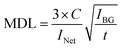
To determine the optimal diameter of the PTFE holes, signal-to-BG (SB) ratios and minimum detection limits (MDLs) were calculated. The SB ratio and MDL for each residue size are listed in Table 2. These values in Al are shown in Fig. 9 as a representative. The SB ratio was calculated by dividing the net intensity by the BG intensity and the MDL was calculated using the following formula:
| |  | (1) |
where
INet is the net intensity (cps),
IBG is the BG intensity (cps),
C is the elemental concentration (ppb = ng g
−1), and
t is the measurement time (s). For each element, the SB ratios were almost equivalent when the APPJ-treated substrates were employed. For Fe Kα, the SB ratios of the 4 and 10 mm diameter residues were 235 ± 2 and 239 ± 20 cps, respectively. However, the SB ratio for the silicone layer in the low-Z elements was the worst owing to the absorption effect. The analytical sensitivity, as determined from the MDL values, were improved by the PTFE mask with a 4 mm diameter. This MDL value was proportional to the square root of
IBG and inversely proportional to
INet; therefore, we conclude that the optimal diameter of the dried residue is 4 mm.
Table 2 MDL (ppb = ng g−1) and SB ratio in each hydrophobic and APPJ-treated substrate. SB ratios were obtained by dividing the net intensity by the BG intensity
| Elements |
With a silicone layer |
APPJ (4 mm mask) |
APPJ (6 mm mask) |
APPJ (8 mm mask) |
APPJ (10 mm mask) |
| MDL (ppb) |
SB ratio |
MDL (ppb) |
SB ratio |
MDL (ppb) |
SB ratio |
MDL (ppb) |
SB ratio |
MDL (ppb) |
SB ratio |
| Al |
5.82 ± 0.74 ×10³ |
1.09 ± 0.10 |
1.86 ± 0.03 ×10³ |
2.23 ± 0.11 |
2.67 ± 0.14 ×10³ |
2.25 ± 0.06 |
3.13 ± 0.89 ×10³ |
2.16 ± 0.10 |
3.78 ± 1.46 ×10³ |
2.13 ± 0.40 |
| P |
1.51 ± 0.25 ×10³ |
3.23 ± 0.32 |
692 ± 17 |
4.47 ± 0.10 |
963 ± 66 |
4.72 ± 0.30 |
1.15 ± 0.33 ×10³ |
4.41 ± 0.15 |
1.31 ± 0.43 ×10³ |
4.60 ± 0.46 |
| K |
161 ± 15 |
27.7 ± 0.50 |
104 ± 4 |
33.4 ± 0.4 |
153 ± 5 |
33.1 ± 1.27 |
167 ± 45 |
33.9 ± 1.3 |
202 ± 61 |
33.7 ± 2.8 |
| Ca |
643 ± 73 |
7.97 ± 0.28 |
444 ± 13 |
9.45 ± 0.31 |
634 ± 26 |
9.87 ± 0.43 |
711 ± 198 |
17.1 ± 0.9 |
873 ± 276 |
9.56 ± 0.68 |
| Fe |
17.3 ± 1.7 |
238 ± 8 |
16.2 ± 0.6 |
235 ± 2 |
23.5 ± 1.4 |
238 ± 7 |
28.1 ± 8.3 |
228 ± 7 |
32 ± 10.1 |
239 ± 20 |
| Sr |
6.45 ± 0.68 |
47.2 ± 2.1 |
6.37 ± 0.31 |
48.6 ± 1.8 |
9.26 ± 0.65 |
49.3 ± 2.7 |
10.7 ± 3.2 |
47.5 ± 1.4 |
12.3 ± 4.1 |
51.7 ± 6.3 |
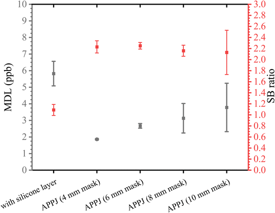 |
| | Fig. 9 MDLs and SB ratios in Al. | |
We obtained recoveries to evaluate the quantitative accuracy of each hydrophobic and APPJ-treated substrate (Table 3). The recoveries were expressed as a percentage and calculated by dividing the quantitative values by the expected value multiplied by 100. For low-Z elements (Al, P, K, and Ca), the quantitative accuracy was low when a hydrophobic substrate was used. Using the APPJ-treated substrate significantly improved the quantitative accuracy and the recoveries were almost 100%. In addition, the quantitative accuracies were similar and did not depend on the APPJ-treated area. In the Sr analysis, the recovery was almost 100% for both the hydrophobic and APPJ-treated substrates. APPJ-treated substrates were used to perform high-accuracy TXRF analysis and both accurate and sensitive analyses in this TXRF instrument was achieved by preparing the dried residue with a 4 mm diameter. In our recent study, the high-intensity area in the TXRF instrument was 4 × 5 mm2.16 The optimal APPJ-treated area obtained in this study was less than that in the high-intensity area and showed results.
Table 3 Recovery in each hydrophobic and APPJ-treated substrate. Recovery is expressed as a percentage and was obtained by dividing the quantitative value in each substrate by the expected value and multiplying by 100. Expected values of Al, P, K, Ca, and Fe were 100 ppm, and that of Sr was 10 ppm
| Elements |
With a silicone layer |
APPJ (4 mm mask) |
APPJ (6 mm mask) |
APPJ (8 mm mask) |
APPJ (10 mm mask) |
| Al |
23.6 ± 5.3 |
102 ± 5 |
103 ± 4 |
106 ± 3 |
108 ± 4 |
| P |
29.5 ± 7.4 |
90.8 ± 1.8 |
93.8 ± 2.7 |
95.9 ± 2.3 |
98.8 ± 3.8 |
| K |
53.0 ± 5.7 |
98.2 ± 2.0 |
96.6 ± 3.8 |
105 ± 4 |
101 ± 4 |
| Ca |
65.0 ± 9.0 |
106 ± 1 |
105 ± 2 |
112 ± 3 |
108 ± 1 |
| Fe |
90.1 ± 3.0 |
96.6 ± 0.6 |
96.6 ± 0.5 |
95.5 ± 0.5 |
97.1 ± 0.3 |
| Sr |
104 ± 5 |
96.6 ± 1.0 |
95.2 ± 1.0 |
100 ± 1 |
97.1 ± 1.1 |
4. Summary
In a previous study, we reported the application of APPJ treatment to prepare a film-type residue for TXRF analysis. As the shape of the dried residue affected the quantitative value, we aimed to optimize the APPJ-treated area in this study. We observed that water droplets on the APPJ-treated substrate spread thinly. When comparing the XPS spectra of quartz glass with and without APPJ treatment, the intensities of the O peaks originating from the silanol groups were increased by APPJ treatment and the intensities of the C peaks originating from organic molecules decreased. In the TXRF analysis of the sample solution, the intensities of the film-type residue, especially for low-Z elements, were higher than those of the dotted-type residue. This result shows that the XRF absorption in the residue decreased. In addition, the RSDs of the quantitative values, MDLs, and recoveries were improved when a PTFE mask with a 4 mm diameter hole was used. Therefore, the optimal APPJ treatment conditions for highly accurate and sensitive TXRF analyses were determined.
Conflicts of interest
There are no conflicts to declare.
Acknowledgements
We acknowledge JSPS KAKENHI grants numbers JP22H02108 and JP21K14655.
References
-
R. Klockenkämper and A. von Bohlen, in Total-Reflection X-Ray Fluorescence Analysis and Related Methods, ed. By M.F. Vitha, Wiley, New York, 2015, p. 126 Search PubMed.
- A. Ohbichi, W. Matsuda, H. Takahara, S. Ikeda, Y. Kataoka, K. Fujii and Y. Koike, Adv. X-Ray Anal., 2018, 62, 126 Search PubMed.
- R. P. Stoessel and A. Prange, Anal. Chem., 1985, 57, 2880 CrossRef CAS.
- E. Maguí, J. Jablan, M. Gerić, S. Iinć, A. M. Domijan, R. Janušić, R. Janušić, B. Šarčević, I. Queralt and V. Garaj-Vrhovac, Anal. Bioanal. Chem., 2019, 411, 1659 CrossRef PubMed.
- P. Wobrauschek, X-Ray Spectrom., 2007, 36, 289 CrossRef CAS.
- M. Regadio, S. Riano, K. Binnemans and T. V. Hoogerstraete, Anal. Chem., 2017, 89, 4595 CrossRef CAS PubMed.
- T. Matsuyama, Y. Izumoto, K. Ishii, Y. Sakai and H. Yoshii, Front. Chem., 2019, 7, 152 CrossRef CAS PubMed.
- K. Tsuji, N. Yomogita and Y. Konyuba, Spectrochim. Acta, Part B, 2018, 144, 68 CrossRef CAS.
- T. Matsuyama, T. Furusato, H. Takahara and K. Tsuji, Adv. X-Ray Anal., 2021, 64, 87 Search PubMed.
- T. Matsuyama, Y. Tanaka, M. Nakae, T. Furusato and K. Tsuji, Analyst, 2022, 147, 5130 RSC.
- K. Tsuji, T. Matsuyama, T. Fukuda, S. Shima, M. Toba, J.-S. Oh and T. Shirafuji, J. Anal. At. Spectrom., 2021, 36, 1873 RSC.
- M. Kim, M. G. Kim, S. R. Kim, H. Y. Chung, J. G. Choi, H. M. Joh, T. H. Chung, H. S. Kim and Y. Kim, J. Korean Phys. Soc., 2013, 63, 996 CrossRef CAS.
- T. Bernhardt, M. L. Semmler, M. Schäfer, S. Bekeschus, S. Emmert and L. Boeckmann, Oxid. Med. Cell. Longevity, 2019, 2019, 3873928 Search PubMed.
- H. Kuwahara and R. Ohyama, J. Phys. Soc. Japan, 2009, 30, 174 Search PubMed.
- K. Tsuji, N. Taniguchi, H. Yamaguchi and T. Matsuyama, X-Ray Spectrom., 2023, 52, 357 CrossRef CAS.
- A. Shimatani, H. Toyoda, K. Orita, Y. Hirokawa, K. Aoki, J.-S. Oh, T. Shirafuji and H. Nakamura, PLoS One, 2021, 16, e0255861 CrossRef CAS.
- J.-S. Oh, E. J. Szili, N. Gaur, S.-H. Hong, H. Furuta, H. Kurita, A. Mizuno, A. Hatta and R. D. Short, J. Phys. D: Appl. Phys., 2016, 49, 304005 CrossRef.
- K. G. Doherty, J.-S. Oh, P. Unsworth, A. Bowfield, C. M. Sheridan, P. Weightman, J. W. Bradley and R. L. Williams, Plasma Processes Polym., 2013, 10, 978 CrossRef CAS.
- J.-S. Oh, O. T. Olabanji, C. Hale, R. Mariani, K. Kontis and J. W. Bradley, J. Phys. D: Appl. Phys., 2011, 44, 155206 CrossRef.
- K. Saranya, S. Bhuvaneswari, S. Chatterjee and N. Rajendran, J. Mater. Sci., 2020, 55, 11582 CrossRef CAS.
- M. Furutani, K. Nakayama, K. Okuma and K. Arimitsu, J. Photopolym. Sci. Technol., 2019, 32, 619 CrossRef CAS.
- S. Kumagai, M. Nakano, K. Takimiya and J. Taleya, Org. Electron., 2018, 62, 548 CrossRef CAS.
- M.-W. Yang and S.-Y. Lin, Colloids Surf., A, 2003, 220, 199 CrossRef CAS.
- H. Nakahiro, P. Zhao, A. Ogino, W. Zheng, Y. Meng and M. Nagatsu, Appl. Phys. Express, 2012, 5, 056201 CrossRef.
- B. Liu, X. Zhang, H. Shioyama, T. Mukai, T. Sakai and Q. Xu, J. Power Sources, 2010, 195, 857 CrossRef CAS.
- R. Abinaya, J. Archana, S. Harish, M. Navaneethan, S. Ponnusamy, C. Muthamizhchelvan, M. Shimomura and Y. Hayakawa, RSC Adv., 2018, 8, 26664 RSC.
- T. A. Otitoju, A. L. Ahmad and B. S. Ooi, J. Ind. Eng. Chem., 2017, 47, 19 CrossRef CAS.
- R. Matsumoto, Y. Nishizawa, N. Kataoka, H. Tanaka, H. Yoshikawa, S. Tanuma and K. Yoshihara, J. Electron Spectrosc. Relat. Phenom., 2016, 207, 55 CrossRef CAS.
- J. Végh, J. Electron. Spectrosc. Surf. Sci., 2004, 563, 183 CrossRef.
|
| This journal is © The Royal Society of Chemistry 2024 |
Click here to see how this site uses Cookies. View our privacy policy here. 
 *a,
Yudai
Tanaka
a,
Naoya
Taniguchi
a,
Jun-Seok
Oh
b and
Kouichi
Tsuji
a
*a,
Yudai
Tanaka
a,
Naoya
Taniguchi
a,
Jun-Seok
Oh
b and
Kouichi
Tsuji
a
 , and expressed as a percentage. The RSDs of the contact angles in the elapsed periods of 0, 0.25, 1, 2, 6, and 10 d were 19.4, 5.80, 6.05, 11.0, 2.13, and 4.47%, respectively. It was observed that the RSD of the contact angle for each elapsed period was unstable.


