
 Open Access Article
 This Open Access Article is licensed under a
 Creative Commons Attribution 3.0 Unported Licence
Scalable fabrication of multi-layered Cu-based electrodes via solvent-free method for the selective electrochemical conversion of CO2 to C2+ products†
Qinhao
Chen
 *ab,
Alexander
Kube
ab,
Bhawna
Rana
a,
Indro
Biswas
a,
Tobias
Morawietz
ac,
Dennis
Kopljar
a and
Kaspar Andreas
Friedrich
*ab
*ab,
Alexander
Kube
ab,
Bhawna
Rana
a,
Indro
Biswas
a,
Tobias
Morawietz
ac,
Dennis
Kopljar
a and
Kaspar Andreas
Friedrich
*ab
aInstitute of Engineering Thermodynamics, German Aerospace Center, Pfaffenwaldring 38-40, 70569 Stuttgart, Germany. E-mail: qinhao.chen@dlr.de; Andreas.Friedrich@dlr.de
bInstitute of Building Energetics, Thermal Engineering and Energy Storage, University of Stuttgart, Pfaffenwaldring 31, 70569 Stuttgart, Germany
cFaculty of Science, Energy and Building Services, Esslingen University of Applied Sciences, Kanalstraße 33, 73728 Esslingen am Neckar, Germany
First published on 16th April 2024
Abstract
In the research field of CO2 electroreduction, gas diffusion electrodes (GDEs) are predominantly manufactured through solvent-based processes. Meanwhile, the solvent-free method has gained heightened attention due to its potential to reduce operational and production expenses, while considering ecological aspects such as solvent evaporation, circulation, and waste treatment. Drawing from its successful applications in other fields, we have specifically developed a solvent-free manufacturing method to produce multi-layered Cu-based GDEs for CO2 electroreduction. The procedure is compatible with industrial production lines, specifically through a roll-to-roll process. By evaluating the interplay between production parameters and electrochemical performance of GDEs via various characterization methods, key factors, i.e., hydrophobicity, gas permeability, thickness, and pore size, were adjusted and applied to achieve a highly selective GDE towards C2+ products (alcohols and ethylene) at industrial relevant currents up to 300 mA cm−2 (ethylene ∼40%, ethanol ∼10%, n-propanol ∼15%).
Introduction
To achieve a carbon-neutral chemical industry, CO2 sourced from industrial and biogenic flue gases or captured directly from the air can be utilized to produce diverse carbon-based materials and chemicals, effectively closing the anthropogenic carbon cycle. Electrochemical reduction of CO2 has gained attention lately,1–3 as it allows integration of renewable electricity to produce high value-added gases, alcohols, and carboxylate4,5 under mild conditions. Among various catalysts, copper (Cu) is the only known element with favourable electrochemical catalytic selectivity towards C2+ products due to its binding affinity to the CO* reaction intermediate and repulsion against underpotential adsorption of hydrogen.6 To facilitate the reaction at industrial rates, a suitable design of gas diffusion electrodes (GDEs) is required which enables an intensified mass-transport of gaseous CO2 and an intimate contact between reactants and catalysts during CO2 electrolysis.5,7 The development of Cu-based GDEs needs particular consideration of layer thickness, porosity, and hydrophobicity to favour the selectivity towards C2+ products owing to the chain reaction mechanism of multi-carbon compounds which is highly dependent on the local reaction conditions.8–12The commonly reported manufacturing procedures for GDEs applied in CO2 electroreduction (CO2RR) involve the deposition of a thin catalyst layer (CL) onto commercially available gas diffusion layers (GDLs) that are typically designed for fuel cells and water electrolysers. The procedures can be further categorized into ink- or slurry-based (drop-casting, hand-painting, air-brushing) and ink-free methods (sputtering, electrodeposition).13,14 Among methods reported in scientific literature of CO2RR, sputtering technology stands out as the sole developed solvent-free method among all ink-free methods, where the selected catalyst particles are ejected via noble gas ions to the targeted substrate by applying high voltages. It generally offers the advantages of high deposition rates, low levels of impurities and scalability. However, it is limited by the high construction and operation costs associated with high voltage applications,14 as well as the deposition of metal-based catalyst without the possibility to include additives such as hydrophobicity agents. On the other hand, industry is familiar with the use of proprietary solvent-free coating methods, such as calendaring, for the production of electrodes. Such approaches have recently gathered renewed interest particularly for coating of battery electrodes, as it has the potential to significantly reduce the operation and production costs in roll-to-roll production lines.15 This is due to a substantially reduced footprint in terms of solvent evaporation and recirculation as well as potential safety aspects when toxic and flammable solvents are to be substituted. Regarding the type of GDEs utilized for CO2RR, it has been suggested by several studies that a certain level of hydrophobicity is advantageous to inhibit the competing H2 evolution and to promote selectivity towards C2+ products. In most cases, this has been done through dispersion of PTFE powders in organic solvents16,17 or the direct application of PTFE emulsion via coating or dip-casting.9 However, the non-dissolvable nature of PTFE in commonly used solvents challenges and complicates the traditional solvent-based procedure to achieve a fine distribution of solid particles.13
In the past, our group has conceptualized a solvent-free method to produce battery electrodes18 and GDEs in alkaline fuel cells.19 Specifically for CO2 electroreduction, we have succeeded in manufacturing single-layered Bi-based GDEs with excellent performance in both the acidic20 and alkaline conditions (FEHCOOH > 90%); however, they suffer from mass transport limitations and carbonate precipitation due to their thick single-layered structure.21 The most recent study conducted by Pellessier et al. has also demonstrated the feasibility and benefits of a solvent-free method for depositing a single-layered Cu catalyst coated with PTFE for the production of C2+ products at very high yields.22 Despite recent advancements in GDE fabrication methodologies, we have further advanced and optimized the solvent-free method, transferring the knowledge at hand to manufacture multi-layered Cu GDEs coated with PTFE. The concept of a multi-layered GDE could be beneficial in introducing distinctive levels of hydrophobicity to prevent in-depth electrolyte penetration and subsequent flooding, as well as carbonate precipitation. Importantly, the individual manufacturing steps are designed to be compatible with a potential roll-to-roll manufacturing process and can be easily scaled-up in dimensions with less complexity and power requirements compared to the only existing solvent-free method – the sputtering technique. Additionally, to achieve state-of-the-art electrode performance and gain a thorough understanding of the critical physical properties of the GDE, the steps are subjected to a comprehensive investigation of their impact on electrode characteristics and electrochemical performance, especially, towards C2+ productions.
Experimental
Electrode compositions and standard manufacturing parameter
The Cu-based catalyst was synthesized based on the recipe from previous studies:16,23 in short, 0.4 M precursor CuCl2 and 10 M NaBH4 aqueous solutions were prepared, respectively, at 45 °C. Both solutions were flushed with N2 for 20 minutes. Subsequently, the prepared NaBH4 solution was slowly dropped into the precursor solution with instantaneous dark precipitation. The received precipitate was then collected, washed, dried, and stored carefully. Aside from the electrode catalyst itself, PTFE (Dyneon, TF 2053Z), nickel mesh (Alfa Aesar) and various carbon materials (Carbon black, acetylene, 50% compressed, 99.9+%, Thermo Scientific Chemicals; VULCAN XC72 Fuel Cell Store; High Surface Area Graphite, HSAG) as the compositions of GDE were purchased for use. XRD characterization of the catalyst can be found in previous work.15 The loading of Cu-based catalyst used in our GDEs weights around 6 wt% on carbon.The developed manufacturing method employs a grinding miller, a calendaring machine, a dry-spraying jet, and a furnace, with the following standard configurations: all powders prepared for this process were ground for 30 seconds in the grinding miller. The calendaring machine was set with a standard force of 100 kg applied to the treated layer, and gap widths of 0.05 mm and 0.30 mm for the gas diffusion layer and the thin catalytic layer deposition, respectively. The dry-spraying jet, which is patented and described in literature, e.g., battery manufacturing,18 was supplied by a nitrogen gas flow with a volumetric flow of 4 slm min−1. The thickness of the layer is determined by the velocity of the substrate and the repetition of the spraying process. The furnace was programmed to ramp up the heating temperature to the desired value within 1 hour and maintain that temperature for an additional hour. Details of the individual manufacturing steps are described in following chapter.
For the comparison purpose, single-layered GDEs was manufactured as the following: the catalyst powder was mixed with the optimal PTFE percentage derived from the multi-layered GDE and pressed into electrodes in a cylindrical mask with subsequent sintering process for 1 h to enhance the mechanical strength of the GDEs.24
Electrochemical measurements
All electrochemical measurements were performed in a commercially available flow cell (Gaskatel) with nickel mesh as anode, the manufactured GDEs as cathode, and a reversible hydrogen electrode (RHE) as reference electrode (RE). The geometric area of the counter and working electrode is 3.14 cm2. The electrolyte used for the CO2RR is 1 M KOH prepared with 18.2 MΩ cm ultra-pure water. During the electrochemical assessment, the electrolyte was pumped via 5 ml min−1 (residence time of approx. 5 min) by an ICC digital pump (Ismatec Reglo ICC Digital Pump, 3-Channel, 8-Roller) through the electrochemical system and disposed directly after the reaction in a single-pass mode. The liquid product for analysis was extracted manually at the catholyte outlet via three-neck valves, the composition of which was subsequently analysed by an offline high-performance liquid chromatograph (HPLC, Agilent Technologies: 1260 Infinity II LC System, Column: Hi-Plex H, 7.7 × 300 mm, 8 μm). The feed CO2 (4.5, purest at Linde) was introduced on the gas side of the GDE with a regulated flow rate of 50.0 mL min−1 controlled by mass-flow controllers (Bronkhorst® EL-Flow Select). The gas flow rate at the outlet was determined via a bubble meter with gas products derived from the analysis by an on-line gas chromatograph (μ-GC, Varian). N2 (5.0, Linde) as joint flow with all gas products allows precise analysis.In the section “Interplay between GDE properties and electrochemical behaviour”, electrochemical performance of various GDEs were tested at the following applied current densities in galvanostatic polarization mode: −100, −200, −250, −300 mA cm−2. In the section “Stability performance”, −200 mA cm−2 was applied until the end of measurement in galvanostatic polarization mode.
Ion-cutting technique and SEM/EDX
For measurements of cross-sectional areas, ion cutting of the GDEs was first performed with a JEOL IB-19520/CCP operated with Argon 5.0 at 6 kV with stage swinging at room temperature. Then, SEM was performed with a Zeiss Crossbeam 350 equipped with Oxford Ultim Max 100 EDX system. The EDX mapping was done at 20 kV, 5 mm working distance and 40 averaged frames at a magnification of 1000×.Surface morphology and composition are investigated through the use of electron microscopy. Scanning electron microscopy (SEM) is conducted using the Zeiss Crossbeam 350 instrument, which is equipped with the Oxford Ultim Max 100 Energy-Dispersive X-ray Spectroscopy (EDX) system. SEM is operated at an accelerating voltage of 2 kilovolts (kV) with a secondary electron (SE) detector, while EDX analysis is conducted at 15 kV to enable deeper sample penetration and enhance signal intensity. In both methods, a working distance of 5 millimetres is maintained, and data is acquired through an averaging of 40 frames at a magnification level of 10![[thin space (1/6-em)]](https://www.rsc.org/images/entities/char_2009.gif) 000×. All sample measurements are conducted under ambient room temperature conditions.
000×. All sample measurements are conducted under ambient room temperature conditions.
X-ray photoemission spectroscopy
Additional chemical analyses of the electrode surfaces were carried out with X-ray photoemission spectroscopy (XPS) in a vacuum system with a base pressure of 2 × 10⁻¹⁰ mbar, using a monochromatic Al K source with an X-ray energy of 1486.74 eV and a hemispherical analyser (ESCALAB Xi+, FEI/Thermo Fisher Scientific). The energy axis of the system was calibrated by adjusting the reference signal of an ion-etched clean silver surface. The fitting of the displayed signals was carried out with Unifit 2016,25 applying convoluted Gaussian/Lorentzian profiles.Gas permeability
The gas permeability of specific GDE was measured using a home-made PMMA cell (cf. Fig. S1†): the electrode (marked red in the schematic drawing) is placed between two flat EPDM seals, where a laminar flow is achieved by slow flow velocities and a constant diameter of 2 cm along the entire cell length, resulting in an investigated area of 3.14 cm−2. The pressure during the measurements were monitored using an absolute pressure transmitter (BD Sensors DMP331, 0–1 bar) as well as a differential pressure transmitter (BD Sensors-DMP 331 0–1 bar diff.), while the flow velocity was regulated via an anemometer (testo 405-V1) with nitrogen gas that has a dynamic viscosity of 17.9 μPa at 25 °C.26In the end, the gas permeability can be determined via Darcy's law for incompressible media based on the pressure and its changes:
 | (1) |
Contact angles
Contact angle measurements were conducted with a simplified home-made setup of optical camera. During the measurement, approx. 15 μL drop of liquid (1 M KOH) was added on top of the surface of the investigated GDE. Then, pictures were captured focusing on the contact between the liquid droplet and the GDE. To avoid the impacts made by potential penetration of microdroplets into the porous gas diffusion layer, pictures were taken at 0 s after dropping in all cases for comparison purposes. In the end, the captured pictures were analysed by ImageJ and the plugin for contact angle analysis.Development of the solvent-free manufacturing method
The multi-layer GDE consists of three functional components:(1) The Ni-based metal mesh, acting as the bottom substrate, functions as a current collector27 and provides support for the mechanic stability of the GDEs in the measurement setup.
(2) The gas diffusion layer (GDL) is comprised of varying types of carbon material and polytetrafluorethylene (PTFE), which serve as a porous and highly hydrophobic medium. Ideally, it effectively ensures unhindered permeability of gas to reach the reactive sites in the catalytic layer and prevents the break-through of the liquid electrolyte to the gas side.9,28
(3) The catalyst layer (CL) which consists of carbon support, catalyst, and PTFE is deposited on top of the GDL, and facilitates CO2RR into value-added products at the three-phase (liquid–gas-catalyst) boundary.
To manufacture the multi-layer GDE, we combine a conventional calendaring method to create a thick GDL with dry-spraying technique in which powder are sprayed in an inert gas flow through a nozzle for applying a very thin catalytic layer on top of it. Subsequently, the layers undergo fixation through an additional heat treatment step. Although not demonstrated as fully integrated process, the design of the individual steps in principle allows seamless integration into a continuous roll-to-roll production scheme for potential upscaling as depicted in Fig. 1 and Fig. S3.† More specifically, two types of powder mixtures are prepared by grinding and mixing different components with a double knife-mill for the GDL (PTFE, carbon support) and CL (PTFE, carbon support, Cu-based catalyst), cf. Experimental section and Methods. The GDL mixture is evenly calendared onto the metal grid, followed by heat treatment at 340 °C slightly above the melting point of the PTFE. After the heat treatment, the CL is sprayed onto the GDL from below via a dry spraying jet with gaseous N2 as feed, coating it with the prepared amount of CL powder. The adhesion of the powder relies on electrostatic forces, hence why this technique is occasionally termed electrostatic spraying. Nevertheless, an additional calendaring step was introduced to improve the fixation followed by another heat-treatment process with the same conditions as above.
 | ||
| Fig. 1 Sketch of the solvent-free method of GDE production for CO2RR. | ||
As a starting point, impacts made by manufacturing parameters on the catalytic layer were studied via a reference GDL made of acetylene black. Different mass loadings (1 mg cm−2, 0.5 mg cm−2, 0.25 mg cm−2) were selected for the fabrication of CL to evaluate the effect of layer thickness and the minimum amount of catalyst required to obtain a uniform layer. For analysis, energy-dispersive X-ray spectroscopy (EDX) was conducted on the cross-sectional area of GDE to investigate the homogeneity of CL deposited on the GDL, as well as its corresponding thickness with the given mass loading of catalyst. Prior to the EDX analysis, samples were prepared by ion-cutting technology to avoid deterioration of the GDE structure and corresponding artefacts during sample preparation.21 As can be seen from Fig. 2a, the GDL (element trace of fluorine from PTFE and carbon from acetylene black) and the CL (element trace of copper from catalyst) can be clearly distinguished from the EDX results of the cross-sectional area, whereas the GDL is less porous than the CL, as evidenced by the SEM images and confirmed by their porosities obtained from Hg-Porosimetry results (GDL ∼ 30%, GDE ∼ 40%). This could be attributed to their different processing procedures in terms of roller distance: thick GDL (0.05 mm); thin CL (0.30 mm). For the sample with loading of 1 mg cm−2, a homogenously deposited thin layer of catalyst at a thickness of around 3–5 μm is obtained as evidenced by the SEM images on top of a approx. 900 μm GDL determined by a thickness meter. Meanwhile, dry-spraying of a lower mass loading of 0.5 mg cm−2 and below has already been proven by SEM/EDX images as inadequate due to non-uniform deposition of copper catalyst on the GDL. As a consequence, while at an intermediate current density of 100 mA cm−2, the obtained electrode still produces a favourable mixture of CO2 reduction products, H2 becomes the dominant product when increasing to higher current densities >200 mA cm−2 as shown in Fig. S2.† The reason is that certain fraction of electrolyte is in direct contact with inert GDL12 which is electrochemically inactive for CO2R. It is evident from the results that the developed solvent-free process is able to produce catalyst layer with an ideal thickness that enables a modulated local concentration of CO2 leading to a better surface concentration of reaction intermediates for *CO dimerization and a favourable pH profile that positively correlates with the thickness and the location of the reaction zone.29 In fact, previous report with airbrush method suggests a 5 μm thick catalyst layer as the best among other thin catalyst layers.12 After the dry spraying, the resulting electrode undergoes a second calendaring process to fixate the catalyst powder onto the G DL. As a decisive parameter, the choice of rolling speed has been identified to have impacts on its surface structure and morphology of the layer as can be seen in Fig. 2b. While a high rolling speed of 10 Hz leads to obvious cracks on the surface of CL, a low rolling speed of 2 Hz is capable of depositing a homogenous catalyst layer onto the GDL without any notable defects. Lastly, to achieve a uniform distribution of PTFE within the GDE,24 an additional heat-treatment process is again applied with the same conditions as above. Since a certain oxidation state of copper has been introduced during the heat-treatment process, X-ray photoelectron spectroscopy (XPS) measurement was conducted to elucidate the surface composition on the post-heated electrode. As can be seen from Fig. 2c, the high resolution XPS data retrieved from the surface clearly indicates the presence of copper and its oxide form evidenced by the characteristic doublet peaks that are composed of Cu 2p1/2 (∼953.6 eV) and Cu 2p3/2 (∼933.8 eV), as well as satellite peaks stemmed from multiple excitations in copper oxides, revealing the different forms of copper: A1 phase Cu2O, A2 phase CuO, A3 absorber species Cu(OH)2, and S1, S2 shake-up photoemission peaks,30,31 which is beneficial for C–C coupling towards multi-carbon products during this heat treatment process by pre-oxidizing copper (+δ) to Cu2+/Cu+.32,33
 | ||
| Fig. 2 (a) SEM/EDX capture of cross-sectional Cu-based GDE (trace: blue-fluor, green-carbon, red-copper). (b) Electron microscope images captured for CL surface at a rolling speed of 2 Hz and 10 Hz. (c) Cu 2p XPS core level spectrum of the annealed GDE (top) with a zoom-in (bottom) in decomposed compositions of Cu 2p3/2. | ||
The developed solvent-free method is compatible with the industrial production line (cf. Fig. S3a†), which results in electrodes with area of 15 cm x 20 cm. The appearance of the electrode is shown in the ESI (cf. Fig. S3b).†
Interplay between GDE properties and electrochemical behaviour
Properties of the gas diffusion layer
To understand the interplay among manufacturing parameters, electrode properties and electrochemical behavior, we further investigated the impact of porosity, hydrophobicity, and gas permeability of the GDL and CL on the performance of CO2RR towards C2+ products by adjusting the production variables (types of carbon support and binder content, outlined in Table S1†). 40 wt% of PTFE as binder in both the GDL and CL has been chosen as the reference value based on previous work.21Previous studies have concluded the important role of GDL as gas diffusion medium for gaseous products and reactants, as well as its hydrophobic barrier towards flooding.9 Providing the porous structure and determining the hydrophobic properties of the GDL, we started by variation of the carbon support to better understand the key characteristics of the GDL for CO2RR. Namely three types of carbon materials, Vulcan X72 (VXC72), high surface-area graphite (HSAG), and acetylene black (AB) with their distinct physical properties were used during GDL manufacturing. As can be seen from Fig. 3a–c, the AB-based GDL exhibits superior electrochemical performance of CO2RR in the range from 100 to 300 mA cm−2 regarding the selectivity towards C2+ products. In addition, it is evident that an optimal working potential exists for the coupling process of C–C bonds16,34,35 (cf.Fig. 3a–c): At a low current density (100 mA cm−2), i.e., low overpotential, hydrogen, and single carbon-atom products (CO and formate) are the main products since the energy level is not favorable for C–C coupling; at higher currents (200–300 mA cm−2) or overpotentials, selectivity towards C2+ products (ethylene, ethanol, and propanol) increases until it reaches the plateau where H2 production increases, most probably due to transport limitation. Meanwhile, C2+ products can only be identified at 200 mA cm−2 on the GDLs made of VXC72 (cf.Fig. 3d). The abrupt increase in potentials on the cathode at the current densities of 250 and 300 mA cm−2 is presumably attributed to the hydrophilicity of VXC72 and the consequent flooding scenario within the GDEs, leading to 100% hydrogen evolution. At the low current density (100 mA cm−2), similar to the case with AB, the working potential has not reached the value for subsequent coupling processes of C–C bonds. As for HSAG 300, it suffers from severe H2 production (∼85% at 100 mA cm−2) within the entire current range studied.
 | ||
| Fig. 3 Faradaic efficiencies of products and recorded potentials during polarization experiments each for 20 minutes (a) using AB as the carbon substrate with (b) focus on H2 and C1 products; (c) C2+ products, (d) using VXC72 as the carbon substrate. (e) Gas permeabilities and contact angles analyzed on each kind of GDL. | ||
To further investigate the reason behind the different electrochemical behavior, we investigated the physical properties of the GDEs. In case of using VXC72 as the carbon material, the gas permeability of the manufactured GDE was measured to be 160 mD which far exceeds the other two candidates (cf.Fig. 3e). However, the contact angle measurements show that the GDL made of VXC72 is less hydrophobic than that of AB, indicating hydrophobicity may play an even more decisive role than the gas permeability in CO2RR (cf.Fig. 3e). In fact, hydrophilic materials may not efficiently prevent flooding on the GDL side which then blocks the essential transport path of CO2 as soon as electrolyte reaches the GDL. This is induced via electrowetting during operations.10 By examining different GDL/MPL compositions, Kim et al. confirmed that a certain level of hydrophobicity must be maintained to avoid flooding while, at the same time, good conductivity and gas permeability needs to be guaranteed.36 Specifically, Liang et al. conducted investigations of CO2RR on electrodes with different binder of polymer substrate of various hydrophobicity. The results have shown that hydrophobic polymers such as poly(vinylpyrrolidone) and poly(vinyl-alcohol) greatly improve the performance of CO2RR towards C2H4.37 As for the GDL made of HSAG 300, minuscule gas permeability is the key limitation and direct consequence for sole H2 production.28 The extremely large overpotential, i.e., the reaction resistance confirms this (cf.Fig. 3d, HSAG: −5.5 V at 100 mA cm−2, therefore not shown).
Properties of the catalyst layer
Moreover, it has been suggested that the content and distribution of PTFE within the CL largely influences its porous structure and hydrophobicity,8 which are crucial for CO2RR. Hence, the weight percentage of PTFE contained within the CL was adjusted (20, 40, 60 wt%) and the impact on the production of C2+ products evaluated.As illustrated by Fig. 4a and d, the CL with 40 wt% of PTFE exhibits the highest selectivity towards C2+ products (∼65%) within the entire measured current density range. Decreasing PTFE to 20 wt% yields comparable results in terms of C2+ production. However, the selectivity towards hydrogen and single carbon atom products (CO and formate) is 10% larger than that of 40 wt% at each measured current density (cf.Fig. 4b and c), suggesting that the coupling process of C–C bound is favoured in the latter case. As for 60 wt% PTFE, hydrogen production is a lot more pronounced (cf.Fig. 4b) and starts dominating already at 200 mA cm−2 whereas it is largely suppressed in the other two cases even when going as high as 300 mA cm−2. Furthermore, the working potentials recorded at various currents (cf.Fig. 4e) clearly shows an overall higher working potential with 60 wt% and 20 wt% PTFE. It is important to note that the change of product selectivity cannot be explained by the different working potentials since different product distributions were obtained at same working potentials on CL of 20 wt% and 40 wt% PTFE, indicating that the complex interplay between hydrophobicity, mass transport of reactants and products or electric conductivity of GDEs play a more important role that will be further studied in the following.
 | ||
| Fig. 4 (a) Faradaic efficiencies of products during polarization experiments each for 20 minutes on GDEs with various PTFE content with (b) focus on H2; (c) C1 products; (d) C2+ products. (e) Corresponding potentials. | ||
For a deeper investigation of the PTFE distribution within the CL, SEM/EDX was conducted on the surface of the GDEs with various PTFE contents. In the upper row of the SEM images shown in Fig. 5, PTFE can be clearly observed on the surface of CL samples with 40 wt% and 60 wt% PTFE. Particularly in the latter one, dense PTFE agglomerates covering the surface can be seen indicating a significant excess of PTFE. As for the 20 wt% sample, accumulation of excessive PTFE could be only be detected in miniscule amount at such magnitude. To investigate further and be able to distinguish between covered and uncovered pore surface, EDX was conducted showing a clear difference of morphologies and surface coverage at different PTFE content as noticeable in the bottom row in Fig. 5. The 20 wt% sample shows large area without PTFE coverage in the EDX mapping of fluorine, whereas large clusters of PTFE are visible, covering the majority area of the catalyst surface. The 40 wt% sample, with an intermediate PTFE content, exhibits a structure uniformly covered with PTFE. The images further reveal a large portion of accessible copper catalyst. Such a homogeneous distribution of PTFE and the resulting hydrophobicity appear to facilitate favorable mass transport conditions for C2+ production without blocking the catalyst surface and porous structure. Kong et al. argue that H2O/CO2 ratio at the active site is another important descriptor besides the catalyst properties, determining the production distribution and can be modulated by adjusting the accessibility of H2O diffusion and CO2 availability.38 In the case at hand, the high hydrophobicity of the uniformly coated porous structure in the 40% sample leads to a low wetting degree of the pores inside the GDE. Accordingly, a rather film-like electrolyte wetting is expected which leads to good accessibility of CO2 due to short diffusion paths through a thin film and restricted H2O diffusion that favor a protonation degree that maximizes C2+ products. In addition, it has been suggested that the presence of PTFE coating could increase CO binding energy and lowers the activation energy for C–C coupling.22
 | ||
| Fig. 5 (First row) REM captures of GDEs/CLs surface with 20, 40, 60 wt% of binder PTFE; (second row) REM/EDX captures tracing the element of carbon (green), fluor (blue), and copper (red). | ||
Stability performance and literature comparison
By controlling a homogenous, pulverization-resistant and crack-free CL with 2 Hz (rolling speed), 340 °C (heat treatment temperature) 1 mg cm−2 (mass loading) and an in-depth parametric study about the choice of carbon materials and PTFE content, the GDE with the highest selectivity towards C2+ could be achieved with the formulation of acetylene black (GDL), 40 wt% PTFE (CL/GDL). Subsequently, the resulting state-of-the-art GDE was tested for its stability performance at an industrial relevant current density (−200 mA cm−2). As can be seen from Fig. 6a, the overall selectivity towards C2+ products remains mostly constant along with low H2 production of 10% for the first four hours at a working potential of approx. −1.70 V vs. RHE at cathode (without iR-correction) (cf. Fig. S4†). After that the faradaic efficiencies of gaseous species starts to exhibit fluctuations with simultaneous increase in H2 production. As at the same time, a breakthrough of electrolyte to the gas side which is in direct contact with the current collector (nickel mesh) was observed, the test was subsequently stopped. It is evident, that the hydrophobic properties of the GDL are not sufficient to prevent the liquid electrolyte from penetrating through the GDL layer. It is suggested that this effect which is induced by electrowetting and capillary forces is likely promoted by the high local alcohol concentration which has a considerably smaller contact angle on the GDE surface compared to the water-based electrolyte.39 We specifically did not investigate this in more detail and neither optimized process conditions or thoroughly look into strategies for enhancing long-term stability. As this work serves as an initial exploration into combining the solvent-free spraying and calendaring methods for GDE manufacturing, we anticipate further improvements in selectivity and stability toward C2+ products through our ongoing efforts. As flooding is acknowledged as a crucial issue, addressing it requires further customization of the GDL's hydrophobic properties.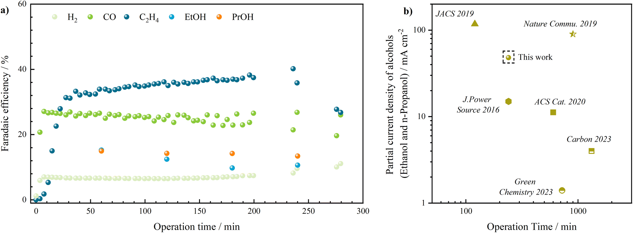 | ||
| Fig. 6 (a) Stability performance of the state-of-the-art GDE at −200 mA cm−2 with selectivity presented: H2 (light green), CO (green), ethylene (dark blue), ethanol (light blue), propanol (orange); (b) literature review comparing the solvent-free manufactured GDEs with other works regarding the partial current density towards alcohols. | ||
Reviewing the current progress in CO2 electroreduction to value-added products, electrochemical production of alcohols is limited by both low partial current density and the poor stability performance.40 To benchmark the viability of the GDEs developed via the solvent-free manufacturing process, stability and partial current densities41 towards alcohols achieved at the end of long-term measurements in reported operation time is compared to literature.42–49 As can be illustrated from Fig. 6b, the GDEs developed in this work via the solvent-free manufacturing process provide state-of-the-art performance compared to traditionally solvent-based manufactured GDEs or MEAs, however, represent especially high selectivity towards n-propanol during long-term CO2 electroreduction. Meanwhile, when we compare the performance of the multi- and thick single-layered GDEs with the same compositions (reported in Bienen et al.'s work21 based on bismuth catalyst), the former demonstrates higher selectivity towards C2+ products (cf. Fig. S5†) owning to the thin catalytic layer, which shortens the diffusion path of gaseous reactants and stabilizes the triple-phase boundary for the reaction. Additionally, the thick single-layered GDE suffers from continuous degradation and increase in hydrogen production which could be improved by the concept of multi-layered GDEs with the thin catalytic layer and an additional hydrophobic layer, thus avoiding the flooding scenario. The nickel gauze, at the same time, further enhances the stability of the GDEs, preventing them from breaking apart, as can be observed with the thick single-layered GDE.
Conclusions
In summary, we have developed a solvent-free procedure that consists of powder grinding, dry spraying, calendaring, and heat treatment to produce multi-layer GDEs based on copper catalyst for CO2 electroreduction in a scalable and reproducible manner. Through systematic investigation of variations in process steps and layer characteristics, we have uncovered the impacts of manufacturing parameters on GDE properties and, consequently, its electrochemical performance toward C2+ products. By selecting acetylene black as carbon material and an amount of 40% PTFE in both the CL and GDL, an optimal balance has been found that led to the highest faradaic efficiencies for C2+ products (ethylene ∼40%, ethanol ∼10%, n-propanol ∼15% at 300 mA cm−2). Stable performance up to several hours could be demonstrated at 200 mA cm−2 before breakthrough of electrolyte to the gas side led to a sudden increase of H2 formation.Beyond the progress in solvent-free production of GDEs for CO2 electroreduction, delving into the interplay between GDE properties and electrochemical behavior through the variation of manufacturing variables offers valuable insights for the advancement of the rational design of GDEs to various products. This could be highly relevant as well for other applications such as ammonia synthesis, metal–air batteries or fuel cells.
Author contributions
Q. C. carried out the electrochemical measurements, elaborated an initial draft and led the conceptualization. A. K. developed the manufactured procedure of GDEs and performed gas permeability tests. R. B. performed SEM/EDX measurements on electrode surface. I. B. performed XPS measurements. T. M. performed ion-cutting and SEM/EDX measurements of the electrode cross-section. D. K. co-designed the experiments, provided supervision, aided in the elaboration and correction of the manuscript. K. A. F. provided supervision, funding and assisted in the elaboration and correction of the manuscript.Conflicts of interest
There are no conflicts to declare.Acknowledgements
The authors wanted to thank Jonas Weidner, Prof. Wolfgang Schuhmann at the university Bochum for the catalyst development, TU Clausthal for the mass production of the catalyst, and Martina Gerle at German Aerospace Center for the measurement of porosity. The research leading to these results has received funding from the BMBF (Bundesministerium für Bildung und Forschung, 033RC017) in the project of ProMet “CO2 zu Propen via eMethanol”.References
- R. I. Masel, Z. Liu, H. Yang, J. J. Kaczur, D. Carrillo, S. Ren, D. Salvatore and C. P. Berlinguette, Nat. Nanotechnol., 2021, 16, 118–128 CrossRef CAS PubMed.
- M. Jouny, W. Luc and F. Jiao, Ind. Eng. Chem. Res., 2020, 59, 8121–8123 CrossRef CAS.
- W. Zhang, Y. Hu, L. Ma, G. Zhu, Y. Wang, X. Xue, R. Chen, S. Yang and Z. Jin, Adv. Sci., 2018, 5, 1700275 CrossRef PubMed.
- Electrochemical Reduction of Carbon Dioxide: Fundamentals and Technologies, ed. J. Qiao, Y. Liu and J. Zang, CRC Press, 2016 Search PubMed.
- Y. Y. Birdja, E. Perez-Gallent, M. C. Figueiredo, A. J. Gottle, F. Calle-Vallejo and M. T. M. Koper, Nat. Energy, 2019, 4, 732–745 CrossRef CAS.
- A. Bagger, W. Ju, A. S. Varela, P. Strasser and J. Rossmeisl, ChemPhysChem, 2017, 18, 3266–3273 CrossRef CAS PubMed.
- N. J. Claassens, C. A. R. Cotton, D. Kopljar and A. Bar-Even, Nat. Catal., 2019, 2, 437–447 CrossRef CAS.
- X. Sheng, W. Ge, H. Jiang and C. Li, Adv. Mater., 2022, 34, 2201295 CrossRef CAS PubMed.
- L. Li, J. Chen, V. S. S. Mosali, Y. Liang, A. M. Bond, Q. Gu and J. Zhang, Angew. Chem., Int. Ed., 2022, 61, e202208534 CrossRef CAS PubMed.
- A. Senocrate, F. Bernasconi, D. Rentsch, K. Kraft, M. Trottmann, A. Wichser, D. Bleiner and C. Battaglia, ACS Appl. Energy Mater., 2022, 5, 14504–14512 CrossRef CAS.
- X. Wang, Z. Wang, F. P. García de Arquer, C.-T. Dinh, A. Ozden, Y. C. Li, D.-H. Nam, J. Li, Y.-S. Liu, J. Wicks, Z. Chen, M. Chi, B. Chen, Y. Wang, J. Tam, J. Y. Howe, A. Proppe, P. Todorović, F. Li, T.-T. Zhuang, C. M. Gabardo, A. R. Kirmani, C. McCallum, S.-F. Hung, Y. Lum, M. Luo, Y. Min, A. Xu, C. P. O'Brien, B. Stephen, B. Sun, A. H. Ip, L. J. Richter, S. O. Kelley, D. Sinton and E. H. Sargent, Nat. Energy, 2020, 5, 478–486 CrossRef CAS.
- Y. C. Tan, K. B. Lee, H. Song and J. Oh, Joule, 2020, 4, 1104–1120 CrossRef CAS.
- H. Rabiee, L. Ge, X. Zhang, S. Hu, M. Li and Z. Yuan, Energy Environ. Sci., 2021, 14, 1959–2008 RSC.
- J. A. Abarca, G. Díaz-Sainz, I. Merino-Garcia, A. Irabien and J. Albo, J. Energy Chem., 2023, 85, 455–480 CrossRef.
- H. Kim, J. H. Lim, T. Lee, J. An, H. Kim, H. Song, H. Lee, J. W. Choi and J. H. Kang, ACS Energy Lett., 2023, 8, 3460–3466 CrossRef CAS.
- Y. Song, J. R. C. Junqueira, N. Sikdar, D. Öhl, S. Dieckhöfer, T. Quast, S. Seisel, J. Masa, C. Andronescu and W. Schuhmann, Angew. Chem., Int. Ed., 2021, 60, 9135–9141 CrossRef CAS PubMed.
- Z. Xing, L. Hu, D. S. Ripatti, X. Hu and X. Feng, Nat. Commun., 2021, 12, 136 CrossRef CAS PubMed.
- D.-W. Park, N. A. Cañas, N. Wagner and K. A. Friedrich, J. Power Sources, 2016, 306, 758–763 CrossRef CAS.
- D. Wittmaier, S. Aisenbrey, N. Wagner and K. A. Friedrich, Electrochim. Acta, 2014, 149, 355–363 CrossRef CAS.
- Q. Chen, A. Kube, D. Schonvogel, D. Kopljar, E. Klemm and K. A. Friedrich, Chem. Eng. J., 2023, 476, 146486 CrossRef CAS.
- F. Bienen, A. Lowe, J. Hildebrand, S. Hertle, D. Schonvogel, D. Kopljar, N. Wagner, E. Klemm and K. A. Friedrich, J. Energy Chem., 2021, 62, 367–376 CrossRef CAS.
- J. Pellessier, X. Gong, B. Li, J. Zhang, Y. Gang, K. Hambleton, C. Podder, Z. Gao, H. Zhou, G. Wang, H. Pan and Y. Li, J. Mater. Chem. A, 2023, 11, 26252–26264 RSC.
- M. Löffelholz, J. Weidner, J. Hartmann, H. Ostovari, J. Osiewacz, S. Engbers, B. Ellendorff, J. R. C. Junqueira, K. Weichert, N. von der Assen, W. Schuhmann and T. Turek, Sustainable Chemistry for Climate Action, 2023, 3, 100035 CrossRef.
- D. Kopljar, A. Inan, P. Vindayer, N. Wagner and E. Klemm, J. Appl. Electrochem., 2014, 44, 1107–1116 CrossRef CAS.
- R. Hesse, T. Chassé and R. Szargan, Fresenius’ J. Anal. Chem., 1999, 365, 48–54 CrossRef CAS.
- S. J. Kim, R. Dean, R. L. Jackson and G. T. Flowers, Tribol. Int., 2011, 44, 125–133 CrossRef CAS.
- N. A. Salleh, S. Kheawhom and A. A. Mohamad, Arabian J. Chem., 2020, 13, 6838–6846 CrossRef CAS.
- L.-C. Weng, A. T. Bell and A. Z. Weber, Phys. Chem. Chem. Phys., 2018, 20, 16973–16984 RSC.
- D. Ren, J. Fong and B. S. Yeo, Nat. Commun., 2018, 9, 925 CrossRef PubMed.
- F. A. Akgul, G. Akgul, N. Yildirim, H. E. Unalan and R. Turan, Mater. Chem. Phys., 2014, 147, 987–995 CrossRef CAS.
- Z. Gan, G. Yu, B. K. Tay, C. Tan, Z. Zhao and Y. Q. Fu, J. Phys. D: Appl. Phys., 2003, 37, 81 CrossRef.
- P.-P. Yang, X.-L. Zhang, F.-Y. Gao, Y.-R. Zheng, Z.-Z. Niu, X. Yu, R. Liu, Z.-Z. Wu, S. Qin, L.-P. Chi, Y. Duan, T. Ma, X.-S. Zheng, J.-F. Zhu, H.-J. Wang, M.-R. Gao and S.-H. Yu, J. Am. Chem. Soc., 2020, 142, 6400–6408 CrossRef CAS PubMed.
- Y. Wang, Z. Wang, C.-T. Dinh, J. Li, A. Ozden, Md. G. Kibria, A. Seifitokaldani, C.-S. Tan, C. M. Gabardo and M. Luo, Nat. Catal., 2020, 3, 98–106 CrossRef CAS.
- H. Noda, S. Ikeda, Y. Oda and K. Ito, Chem. Lett., 1989, 18, 289–292 CrossRef.
- Y. Wang, J. Liu and G. Zheng, Adv. Mater., 2021, 33, 2005798 CrossRef CAS PubMed.
- B. Kim, F. Hillman, M. Ariyoshi, S. Fujikawa and P. J. A. Kenis, J. Power Sources, 2016, 312, 192–198 CrossRef CAS.
- M. Li, M. N. Idros, Y. Wu, T. Burdyny, S. Garg, X. S. Zhao, G. Wang and T. E. Rufford, J. Mater. Chem. A, 2021, 9, 19369–19409 RSC.
- X. Kong, C. Wang, Z. Xu, Y. Zhong, Y. Liu, L. Qin, J. Zeng and Z. Geng, Nano Lett., 2022, 22, 8000–8007 CrossRef CAS PubMed.
- D. Corral, J. T. Feaster, S. Sobhani, J. R. DeOtte, D. U. Lee, A. A. Wong, J. Hamilton, V. A. Beck, A. Sarkar, C. Hahn, T. F. Jaramillo, S. E. Baker and E. B. Duoss, Energy Environ. Sci., 2021, 14, 3064–3074 RSC.
- D. Wakerley, S. Lamaison, J. Wicks, A. Clemens, J. Feaster, D. Corral, S. A. Jaffer, A. Sarkar, M. Fontecave, E. B. Duoss, S. Baker, E. H. Sargent, T. F. Jaramillo and C. Hahn, Nat. Energy, 2022, 7, 130–143 CrossRef CAS.
- D. Ren, Y. Deng, A. D. Handoko, C. S. Chen, S. Malkhandi and B. S. Yeo, ACS Catal., 2015, 5, 2814–2821 CrossRef CAS.
- Y. C. Li, Z. Wang, T. Yuan, D.-H. Nam, M. Luo, J. Wicks, B. Chen, J. Li, F. Li, F. P. G. de Arquer, Y. Wang, C.-T. Dinh, O. Voznyy, D. Sinton and E. H. Sargent, J. Am. Chem. Soc., 2019, 141, 8584–8591 CrossRef CAS PubMed.
- R. Qiu, J. Jia, L. Peng, R. Li, S. Yan, J. Li, J. Zhang, D. T. Sun, Z. Lan and T. Xue, Green Chem., 2023, 25, 684–691 RSC.
- X. Wang, Z. Wang, F. P. García de Arquer, C.-T. Dinh, A. Ozden, Y. C. Li, D.-H. Nam, J. Li, Y.-S. Liu and J. Wicks, Nat. Energy, 2020, 5, 478–486 CrossRef CAS.
- S. Ma, M. Sadakiyo, R. Luo, M. Heima, M. Yamauchi and P. J. Kenis, J. Power Sources, 2016, 301, 219–228 CrossRef CAS.
- X. Liu, Y. Hou, F. Yang, Y. Liu, H. Yu, X. Han, J. Chen, S. Chen, S. Zhou and S. Deng, Carbon, 2023, 201, 460–466 CrossRef CAS.
- M. Luo, Z. Wang, Y. C. Li, J. Li, F. Li, Y. Lum, D.-H. Nam, B. Chen, J. Wicks and A. Xu, Nat. Commun., 2019, 10, 5814 CrossRef CAS PubMed.
- N. Sakamoto, Y. F. Nishimura, T. Nonaka, M. Ohashi, N. Ishida, K. Kitazumi, Y. Kato, K. Sekizawa, T. Morikawa and T. Arai, ACS Catal., 2020, 10, 10412–10419 CrossRef CAS.
- W. Sun, P. Wang, Y. Jiang, Z. Jiang, R. Long, Z. Chen, P. Song, T. Sheng, Z. Wu and Y. Xiong, Adv. Mater., 2022, 34, 2207691 CrossRef CAS PubMed.
Footnote |
| † Electronic supplementary information (ESI) available. See DOI: https://doi.org/10.1039/d4gc00711e |
| This journal is © The Royal Society of Chemistry 2024 |