 Open Access Article
Creative Commons Attribution 3.0 Unported Licence
Morphology, dynamic disorder, and charge transport in an indoloindole-based hole-transporting material from a multi-level theoretical approach†
Manuel
Pérez-Escribano‡
 a,
Alberto
Fernández-Alarcón‡
 a,
Enrique
Ortí
 a,
Juan
Aragó
 a,
Jesús
Cerdá
 *b and
Joaquín
Calbo
 *a
*a
aInstituto de Ciencia Molecular, Universidad de Valencia, 46890 Paterna, Spain. E-mail: joaquin.calbo@uv.es
bLaboratory for Chemistry of Novel Materials, Materials Research Institute, University of Mons-UMONS, Mons 7000, Belgium. E-mail: jesus.cerdacalatayud@umons.ac.be
First published on 21st August 2023
Abstract
The exponential effort in the design of hole-transporting materials (HTMs) during the last decade has been motivated by their key role as p-type semiconductors for (opto)electronics. Although structure–property relationships have been successfully rationalized to decipher optimal site substitutions, aliphatic chain lengths or efficient aromatic cores for enhanced charge conduction, the impact of molecular shape, material morphology and dynamic disorder has been generally overlooked. In this work, we characterize by means of a multi-level theoretical approach the charge transport properties of a novel planar small-molecule HTM based on the indoloindole aromatic core (IDIDF), and compare it with spherical spiro-OMeTAD. Hybrid DFT calculations predict moderate band dispersions in IDIDF associated to the main transport direction characterized by π–π stacked molecules, both between the indoloindole cores and the thiophene groups. Strongly coupled dimers show relevant non-covalent interactions (NCI), indicating that NCI surfaces are a necessary but not exclusive requirement for large electronic couplings. We evidence remarkable differences in the site energy standard deviation and electronic coupling distributions between the conduction paths of IDIDF and spiro-OMeTAD. Despite the spherical vs. planar shape, theoretical calculations predict in the static crystal strong direction-dependent charge transport in the two HTMs, with ca. one-order-of-magnitude higher mobility (μ) for IDIDF. The dynamical disorder promoted by finite temperature effects in the crystal leads to a reduction in the hole transport properties in both HTMs, with maximum μ values of 2.42 and 4.2 × 10⁻² cm2 V−1 s−1 for IDIDF and spiro-OMeTAD, respectively, as well as a significant increase in the transport anisotropy in the latter. Finally, the impact of the material amorphousness in the hole mobility is analysed by modelling a fully random distribution of HTM molecules. An average (lower-bound) mobility of 1.1 × 10⁻³ and 4.9 × 10⁻⁵ cm2 V−1 s−1 is predicted for planar IDIDF and spherical spiro-OMeTAD, respectively, in good accord with the experimental data registered in thin-film devices. Our results demonstrate the strong influence of molecular shape, dynamic structural fluctuations and crystal morphology on the charge transport, and pose indoloindole-based HTMs as promising materials for organic electronics and photovoltaics.
1. Introduction
Hole-transporting materials (HTMs) are one of the crucial components of photovoltaic devices with dye-sensitized (DSC) and perovskite-sensitized (PSC) active layers. HTMs are used to transport photogenerated holes in the active layer to the electrodes, and to prevent mechanical active-layer/electrode contacts. Compared to the inorganic analogues, organic HTMs as p-type semiconductors have the advantages of being biodegradable, low cost, and easily processed.1 To achieve high power conversion efficiencies (PCEs) and long-term device stabilities, however, novel HTMs with a proper structural and chemical design, appropriate energy level offsets, high crystallinity and high hole mobility (>10−3 cm2 V−1 s−1) are required.2Tremendous efforts in synthesizing an increasing number of HTMs have been expended over the last decade.3–6 Among them, spiro-OMeTAD [2,2′,7,7′-tetrakis(N,N-di-p-methoxyphenyl-amine)9,9′-spirobifluorene], consisting of two perpendicular fluorene moieties with methoxyphenyl-amine substituents (see Fig. 1), is arguably one of the most recognized organic HTMs, boosting the rapid development of PSCs exceeding PCEs of 21%.7 The spiro-type central structure confers an orthogonal configuration, which acts in favour of morphological stability. Meanwhile, the peripheral arylamine units in spiro-OMeTAD allow suitable energy level alignment, and the pendent methoxy groups (–OMe) facilitate solution processability. High mobilities for single-crystal field-effect transistors have been reported around 10−3 cm2 V−1 s−1, three orders of magnitude higher than that found in thin-film devices;8 thus, crystallinity plays a key role in device engineering for optimal performance.
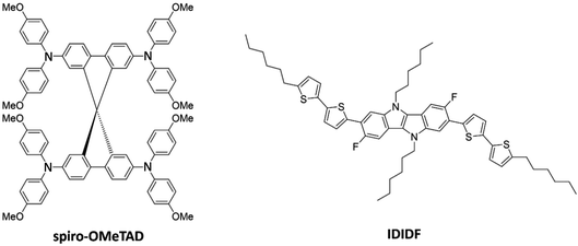 | ||
| Fig. 1 Chemical structure of spiro-OMeTAD and the indolo[3,2-b]indole-based IDIDF hole-transporting materials. | ||
The substituent position of the –OMe group in spiro-OMeTAD is found to have strong impacts on the materials’ properties, such as the electron-donor/withdrawing character, allowing tunability of the optical bandgap.9 On the other hand, the adjustment of the electron donating ability through the pendant groups is proved to be another efficient way to fine-tune the energy levels, e.g. substituting the –OMe groups by ethyl, N,N-dimethylamino or methylsulfanyl moieties.10 Still, spiro-OMeTAD HTMs present several disadvantages such as the requirement of dopants and additives to increase charge transport at the expense of enhanced degradation. Moreover, the complex multistep procedure for their synthesis and purification hinders commercialization due to exceptionally high costs.
HTMs based on other spiro-type structures have been developed, including heterocyclic moieties based on nitrogen,11–13 oxygen14–16 and sulphur.17 On the other hand, non-spiro core-based HTMs containing thiophenes,18–20 triazatruxenes,21 azulenes,22 tetrathiafulvalene,23 carbazole24,25 or phenothiazine,26 among others, have shown promising PCEs in the range 10–23%, including the poly[bis(4-phenyl)(2,4,6-trimethylphenyl)amine] (PTAA) and poly(3-hexylthiophene-2,5-diyl) (P3HT) systems, which hold record PCEs of ca. 22% among polymeric HTMs.27,28
A linear fluorinated indolo[3,2-b]indole core unit-based HTM (IDIDF) was reported by Park et al. (Fig. 1),29 showing one order of magnitude higher hole mobility (1.7 × 10⁻³ cm2 V−1 s−1) compared to referable spiro-OMeTAD in space-charge-limited-current measurements, and superior photovoltaic performance for perovskite solar cells. The high charge-carrier transport was explained by the tight and parallel molecular arrangement stacked by strong π–π interactions, which contrasts to the spherical shape of spiro-OMeTAD. The indoloindole core was previously used to characterize the nonfluorinated 4H4TIDID analogue, which presented an extraordinary field-effect mobility of 0.97 cm2 V−1 s−1 for a vacuum-deposited polycrystalline device.30 More recently, a family of IDIDF-based HTMs has been synthesized with varying alkyl chain position and length, leading to PCEs as high as 23% in non-doped and 24% in doped conditions, as well as outstanding thermal and moisture stabilities.31 Despite the promising characteristics of this new class of indoloindole HTMs, a detailed analysis on the importance of a well-packed π–π stacking and the dynamic disorder, as well as the impact of mesoscale ordering and anisotropy, in their charge-carrier transport properties is missing so far.
From the experimental point of view, manufacturing variability, layer homogeneity and/or crystallinity, interface morphology, structural orientation, presence of trap defects or stability issues, among others, inhibit precise comparison of the hole mobility in a series of HTMs. In this regard, theoretical chemistry and computational modelling has proved crucial to deepen the understanding of charge transport and the key factors affecting it, boosting the development of next-generation hole-transporting materials. For example, studies employing state-of-the-art ab initio calculations, multiscale modelling and/or kinetic Monte Carlo simulations shed light on the impact of anisotropy,32 mesoscale ordering,33 amorphousness,34 substituent connectivity35,36 or aliphatic side chain engineering in the charge transport of HTMs, allowing guidance prior to experimentation. The role of disorder, nature of the semiconductor–dielectric interface and presence of non-ohmic contacts can also be assessed theoretically, allowing for the first time a robust molecular-scale description of a field-effect transistor operation.37 Finally, big-data science and machine-learning algorithms are being applied to high-throughput screening of HTMs for the discovery of new candidates with unprecedented performances or develop cost-effective theoretical approaches for large-scale modelling.38,39
In this work, we perform a detailed analysis of the charge transport properties of a recently reported indoloindole-based hole-transporting material (IDIDF), and compare it throughout with reference spiro-OMeTAD. First, the crystal and electronic structure is calculated, and the different paths for hole transport are characterized. A multi-level theoretical protocol combining ab initio calculations, molecular dynamics and kinetic Monte Carlo simulations was applied to predict hole mobilities in the static crystal, and to determine the effect of dynamic disorder by means of finite temperature structural fluctuations. Non-covalent interactions were analysed for most representative conduction paths. The impact of the molecular shape and the self-assembly crystal packing along the efficient charge-transport paths was disentangled by comparing the structural isotropy, site energy and electronic coupling distributions on the planar-like IDIDFvs. the spherical-like spiro-OMeTAD. Finally, random amorphous phases of the two HTMs were modelled to unravel the impact of crystallinity on their charge transport properties.
2. Computational details
Minimum-energy crystal structures were obtained under the density functional theory (DFT) framework by using the gradient-generalized approximation through the PBEsol functional,40 a 4 × 4 × 4 k-point grid mesh and the “light” tier-1 numerically atom-centred orbital basis set, as implemented in FHI-aims.41 Single-point electronic structure calculations were performed with the hybrid meta-GGA HSE06 functional using the same k-point grid mesh to explore the Brillouin zone. A k-path following the high-symmetry points of X–Γ–Y|L–Γ–Z|N–Γ–M|R–Γ was chosen according to the centrosymmetric triclinic space group P![[1 with combining macron]](https://www.rsc.org/images/entities/char_0031_0304.gif) of spiro-OMeTAD and IDIDF. Effective masses for holes and electrons were obtained according to the finite differences method as implemented in the effmass code.42 Frontier crystal and molecular orbitals were represented by means of the VESTA43 and Chemcraft software.44
of spiro-OMeTAD and IDIDF. Effective masses for holes and electrons were obtained according to the finite differences method as implemented in the effmass code.42 Frontier crystal and molecular orbitals were represented by means of the VESTA43 and Chemcraft software.44
The shape of the HTMs was evaluated by employing an isotropic index (ISO) calculated as the fraction between the smallest and the largest eigenvalue of the inertia tensor. To do so, the centre of mass was first computed, and then the coordinates were translated to that point. Subsequently, the inertia tensor was calculated, and the eigenvalues were obtained. Using this parameter, a value of ISO = 1 indicates a fully isotropic system, such as methane or fullerene, and an ISO approaching 0 is related to a highly anisotropic structure.
The non-covalent interactions involved in relevant dimers of the HTM materials were analysed through the reduced density gradient (RDG), or NCI index, by means of the NCIPLOT package.45 Promolecular densities, which are accurate enough for a semi-quantitative analysis of the non-covalent interactions, were used to save computational resources. Graphical representations of the NCI index were performed by means of the VMD software using standard cutoffs of ρ = 0.5 a.u. and RDG = 1.0 a.u. for the calculation, and of RDG = 0.3 a.u. for the isosurface visualization.
According to the high localization of the polaron generated in a single molecule, we applied the Marcus theory for calculating the rate constants between dimers on each relevant direction through the formula:
 | (1) |
The reorganization energy was obtained by means of the four-point approximation:
| λ = (E+g0 − E+g+) + (E0g+ − E0g0) | (2) |
The electronic coupling V in dimers was estimated according to the dimer Fock operator with frontier orbitals of two neighbouring monomers based on a dimer projection (DIPRO).50 In this approximation, the adiabatic molecular orbitals of a dimer are expressed as a linear combination of the molecular orbitals of the isolated monomers, and the monomer diabatic energies and the electronic coupling are obtained after solving the corresponding secular equation. The wavefunction used to compute the electronic coupling was obtained at the B3LYP/6-31G(d,p) level of theory.
The mobility of charge carriers was assessed by considering the most relevant paths. In the crystalline phases, we considered a 5 × 5 × 5 supercell for IDIDF (125 molecules) and 3 × 3 × 3 for spiro-OMeTAD (54 molecules), and the crystalline structure was minimized using the experimental crystal cell parameters at the molecular mechanics level under the scalable molecular dynamics NAMD program package.51 The web-based graphical interface CHARMM-GUI was employed for the automatic parameterization of the HTMs using the CHARMM general force-field (CGenFF).52 A kinetic Monte Carlo (kMC) program was coded to compute the hole mobility according to the direct method based on the Gillespie algorithm (see ESI† for further details).53 All possible paths were considered for first- and second-nearest neighbours. Electronic couplings in dimers higher than a threshold of 1 meV were chosen as non-negligible charge transport paths. For kMC diffusion convergence, 5000 simulations of 10 and >1000 ns for crystalline and amorphous phases, respectively, were used, whereas an electric field of 104 V cm−1 was applied in all the directions of ab, ac and bc crystallographic planes for static and dynamic crystal cells, or xy, xz and yz coordinate planes in the case of the amorphous materials.
Dynamic disorder due to finite temperature structural fluctuations on the charge transport properties of our HTMs were considered by performing NVT molecular dynamics (MD) simulations using the experimental crystal lattice parameters and the CGenFF force-field. MD simulations were performed along 500 ps with a time step of 2 fs and a temperature of 298 K. Crystal structure snapshots were extracted every 1 ps of the last 200 ps in a total of 200 geometries. The previously selected dimers with relevant electronic couplings for the static crystal structure were analysed during the dynamics to obtain a Gaussian distribution of site energy differences (ΔĒ ± σ) and couplings (![[V with combining macron]](https://www.rsc.org/images/entities/i_char_0056_0304.gif) ± σ). These parameters were set as input to perform kMC simulations and predict the dynamic disorder effect of temperature on the mobility (see the ESI†). Anisotropy in charge transport was elucidated by computing the mobility along the ab, ac and bc crystallographic planes in steps of 10°. Anisotropy plots of mobility were generated by means of the matplotlib library in python.54
± σ). These parameters were set as input to perform kMC simulations and predict the dynamic disorder effect of temperature on the mobility (see the ESI†). Anisotropy in charge transport was elucidated by computing the mobility along the ab, ac and bc crystallographic planes in steps of 10°. Anisotropy plots of mobility were generated by means of the matplotlib library in python.54
Finally, amorphous phases were modelled starting from a random molecular packing including 54 and 100 molecules for spiro-OMeTAD and IDIDF materials, respectively, using the PackMol software.55,56 Lattice parameters were fully optimized in an orthorhombic shape until convergence. In this case, long MD simulations of up to 200 ns using a time step of 2 fs were performed to explore the large conformational space and randomness of molecular positions (snapshot extraction every 1 ns). In contrast to the dynamic disorder analysis, all first-nearest neighbours were considered for dimers, and joined in a unique distribution. For the kMC simulations, a regular grid of equidistant cubic-like disposition of the molecules with a mean distance as extracted from the molecular dynamics of 200 ns was assumed, with the site energy differences and electronic couplings derived from normal distributions as extracted along the dynamics.
3. Results and discussion
3.1. Static crystals
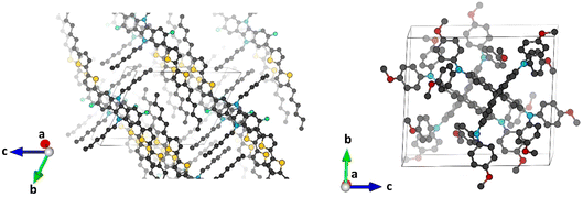
Minimum-energy crystal structures of indoloindole-based IDIDF and reference spiro-OMeTAD HTMs were obtained upon full atomic and unit cell relaxation at the PBEsol level (Fig. 2). Theoretical calculations predict lattice parameters very close to the experimental ones, within a maximum deviation of 1.7 and 1.6% for IDIDF and spiro-OMeTAD, respectively (see Tables S1 and S2†). Inclusion of the van der Waals (vdW) dispersion correction to account for the non-covalent interactions leads to an over-compression of the unit cell, resulting in larger discrepancies with respect to the experimental data. Although its better performance is probably due to error cancellation (neglect of thermal effects and dispersion interactions), the dispersion non-corrected methodology was selected for subsequent electronic structure analysis.Single-point electronic structure calculations were performed on the HTMs at the hybrid-DFT HSE06 level of theory. As expected, the band structure of spiro-OMeTAD presents very flat bands along all k-segments of the reciprocal space, both for the top of the valence band (or valence band maximum, VBM) and for the bottom of the conduction band (or conduction band minimum, CBM), with effective masses for electrons and holes >10 m0 and a direct bandgap of 2.974 eV centred at Γ. These results indicate a high localization of the wavefunction (Fig. 3; see Fig. S1† for full band structure diagrams), and therefore a hopping mechanism of charge transport. In relative contrast, the band structure of IDIDF displays moderate dispersion in both VBM and CBM (Fig. 3). In this case, effective masses in the range of 0.7–1.8 m0 were computed for the hole and electron. Theoretical calculations predict an indirect nature of the bandgap for IDIDF, which is calculated at 1.885 eV (Γ–X) – the smallest direct bandgap is calculated at 2.148 eV in R (Fig. S1†).
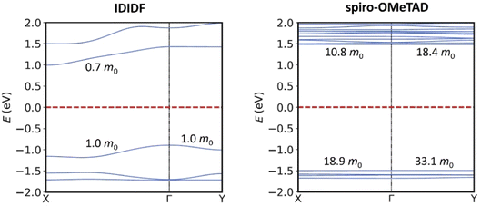 | ||
| Fig. 3 Band structure calculated at the HSE06 level for IDIDF (left) and spiro-OMeTAD (right) on the PBEsol-optimized crystal geometries. Only two k-segments are displayed for simplicity (see Fig. S1† for full band structure diagrams). Relevant effective masses for holes (in the VBM) and for electrons (in the CBM) are indicated. | ||
As shown by the highest-occupied molecular orbital of the molecular systems (Fig. S2†), the hole in IDIDF is generated over the full π-conjugated backbone constituted by the indoloindole core and the peripheral bithiophene moieties, with negligible participation of the aliphatic chains. On the other hand, the hole in spiro-OMeTAD is delocalized over the fluorene core and extends through the methoxyphenyl-amine pendant groups. Crystal orbital representation of the VBM and CBM of IDIDF indicates a certain delocalization of the electronic structure (Fig. S3†), suggesting a limit case to consider a hopping mechanism. Similarly, although presenting a flat band structure, the VBM in spiro-OMeTAD is partially shared between proximal fluorenes of vicinal moieties (Fig. S3†). The localized nature of the hole charge carrier in both HTMs is however supported by the single-molecule localization of the spin density upon considering hole formation (IDIDF+ and spiro-OMeTAD+) in the most interacting dimers (Fig. S4†).
To further confirm the viability of applying a hopping transport regime in our materials, the reorganization energy (λ) of spiro-OMeTAD and IDIDF was computed at the BMK/6-31(d,p) level, and compared with a rough estimation of the electronic coupling extracted from the VBM depth. Theoretical calculations indicate that spiro-OMeTAD presents a reorganization energy of 302 meV, in good accord with previous reports.49 On the other hand, the highly π-conjugated structure of IDIDF is predicted with a similar λ (313 meV) compared to reference spiro-OMeTAD, supporting its suitability for hole conduction. In both cases, λ is notably larger than the electronic coupling estimated preliminarily at 0.13 and 67 meV in spiro-OMeTAD and IDIDF, respectively, from the VBM depth. These results therefore confirm the valid assumption of a hopping regime and the application of Marcus theory to study the charge transport properties in these HTMs.57
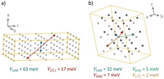
The different shape of the spherical-like spiro-OMeTAD and the more planar and longitudinal IDIDF molecules may be translated into a different crystal morphology and hole-transport directionality. To measure the level of geometrical isotropy in these two HTMs, we calculated the ratio between the smallest and largest eigenvalue of the inertia tensor, hereafter ISO index (values close to 1 indicate spherical structures and ISO close to 0 imply strong anisotropy; see Computational details). In particular, we predict an ISO index of 0.688 and 0.091 for spiro-OMeTAD and IDIDF, respectively, which emphasizes the high level of structural anisotropy of the latter compared to the spiro HTM. This level of anisotropy, accompanied by the consequent self-assembling morphology in the crystal, is translated into preferential directions for charge transport. For example, in the crystal structure of spiro-OMeTAD, we predict up to four directions where relevant electronic couplings between neighbours must be considered for subsequent mobility calculations (Fig. 4). In contrast, IDIDF presents only two directions with important electronic coupling (direction 100 with V = 63 meV, and direction 2![[1 with combining macron]](https://www.rsc.org/images/entities/char_0031_0304.gif) 1 with V = 17 meV). Note that one of the main transport directions in IDIDF is predicted between second neighbours, suggesting the necessity of exploring further than first neighbours in highly anisotropic HTMs.
1 with V = 17 meV). Note that one of the main transport directions in IDIDF is predicted between second neighbours, suggesting the necessity of exploring further than first neighbours in highly anisotropic HTMs.
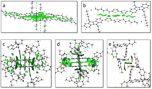
The non-covalent interactions (NCI) index was calculated to unveil the relation between the weak interacting forces governing the crystal assembly and the coupling between vicinal molecules. In IDIDF, the main conduction path 100 is characterized by dimers that interact with a large surface of NCIs, as evidenced by the graphical representation of the reduced density gradient in Fig. 5 (see Computational details). The NCI surface confirms the strong interaction between the aromatic cores of vicinal IDIDF entities, with π–π distances of 3.3–3.6 Å between indoloindole cores and of 3.8–4.0 Å between thiophene moieties, as well as the proximity between the aliphatic chains (ca. 2.8 Å) that further stabilize the packing through CH⋯HC aliphatic interactions (Fig. 5a). On the other hand, the NCI analysis for the 2![[1 with combining macron]](https://www.rsc.org/images/entities/char_0031_0304.gif) 1 dimer predicts short contacts of 3.8 Å between the thiophene moieties, and the interaction extends through the aliphatic chains with the peripheral benzene rings of the fluoro-indole groups through CH⋯π contacts at 2.8 Å (Fig. 5b). Otherwise, the main interacting dimers in the spiro-OMeTAD crystal are calculated with a large NCI surface (Fig. 5c and d). Note that the unit cell of spiro-OMeTAD contains two inequivalent molecules so we compute two different types of dimers along a direction (100 with next cell and 000 within the same cell; Fig. 4). Despite the large differences in terms of V, these dimers present similar NCI surfaces located mainly between the aromatic rings of the interacting monomers, with π–π distances as short as 3.2–4.0 Å. The other directions with weak electronic couplings are characterized by relatively small NCI surfaces involving the peripheral methoxyphenyl groups (Fig. 5e and S5†).
1 dimer predicts short contacts of 3.8 Å between the thiophene moieties, and the interaction extends through the aliphatic chains with the peripheral benzene rings of the fluoro-indole groups through CH⋯π contacts at 2.8 Å (Fig. 5b). Otherwise, the main interacting dimers in the spiro-OMeTAD crystal are calculated with a large NCI surface (Fig. 5c and d). Note that the unit cell of spiro-OMeTAD contains two inequivalent molecules so we compute two different types of dimers along a direction (100 with next cell and 000 within the same cell; Fig. 4). Despite the large differences in terms of V, these dimers present similar NCI surfaces located mainly between the aromatic rings of the interacting monomers, with π–π distances as short as 3.2–4.0 Å. The other directions with weak electronic couplings are characterized by relatively small NCI surfaces involving the peripheral methoxyphenyl groups (Fig. 5e and S5†).
3.2. Dynamic disorder
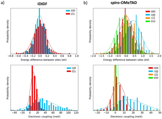
To shed light on the dynamic disorder promoted by structural fluctuations at room temperature on the charge transport, we performed NVT molecular dynamics on the minimum-energy crystal structure of spherical-like spiro-OMeTAD and planar IDIDF up to 500 ps. The timestep was chose to be 2 fs and snapshot extraction was made every 1 ps for the last 200 ps to have vibrational motion resolution. The electronic coupling was sampled for the most relevant dimers obtained in the previous section for the static crystals. First, we recomputed the isotropic ISO parameter along the 200 snapshots of the dynamics simulation. Theoretical calculations predict normal distributions with a mean ISO value of 0.657 (σ = 0.012) and 0.089 (σ = 0.003) for spiro-OMeTAD and IDIDF, respectively (Fig. S6†), to be compared with 0.688 and 0.091 obtained in the static crystal. These results indicate that, whereas the IDIDF molecule maintains its large anisotropy, a significant increase in anisotropy is predicted for spherical-like spiro-OMeTAD due to the room-temperature structural deformations.The site energy difference and electronic coupling distributions along the dynamics between the relevant monomer pairs were calculated and fitted to a Gaussian function. In IDIDF, the site energy differences nicely correlate to a normal distribution, with a mean ΔĒ value centred at zero (Fig. 6a) and a deviation slightly larger for the dimer 2![[1 with combining macron]](https://www.rsc.org/images/entities/char_0031_0304.gif) 1 (σ = 179 meV) compared to dimer 100 (σ = 131 meV). The mean electronic coupling, however, significantly differs between the two dimers: [
1 (σ = 179 meV) compared to dimer 100 (σ = 131 meV). The mean electronic coupling, however, significantly differs between the two dimers: [![[V with combining macron]](https://www.rsc.org/images/entities/i_char_0056_0304.gif) = 36, σ = 31 meV] for dimer 100, and [
= 36, σ = 31 meV] for dimer 100, and [![[V with combining macron]](https://www.rsc.org/images/entities/i_char_0056_0304.gif) = 9, σ = 8 meV] for dimer 2
= 9, σ = 8 meV] for dimer 2![[1 with combining macron]](https://www.rsc.org/images/entities/char_0031_0304.gif) 1 (Fig. 6a). The
1 (Fig. 6a). The ![[V with combining macron]](https://www.rsc.org/images/entities/i_char_0056_0304.gif) obtained for dimers 100 and 2
obtained for dimers 100 and 2![[1 with combining macron]](https://www.rsc.org/images/entities/char_0031_0304.gif) 1 are therefore smaller than those calculated in the static crystal (63 and 17 meV, respectively), suggesting the detrimental character of the dynamic disorder on the charge transport.
1 are therefore smaller than those calculated in the static crystal (63 and 17 meV, respectively), suggesting the detrimental character of the dynamic disorder on the charge transport.
Moving to spiro-OMeTAD, we predict again a set of well-fitted Gaussian distributions for site energy differences in the four relevant types of dimers. In this case, despite not all distributions being centred at zero (ΔĒ from −204 to 425 meV), they present similar dispersions (σ in the range of 399–481 meV), which are conspicuously larger than for IDIDF (Fig. 6b). The higher σ values obtained in spiro-OMeTAD indicate stronger structural fluctuations along the dynamics, which is in good accord with the dispersion trends of the isotropic index. In terms of electronic couplings, distributions with [![[V with combining macron]](https://www.rsc.org/images/entities/i_char_0056_0304.gif) = 16, σ = 16 meV] for dimer 100 and [
= 16, σ = 16 meV] for dimer 100 and [![[V with combining macron]](https://www.rsc.org/images/entities/i_char_0056_0304.gif) = 4, σ = 6 meV] for dimer 000 were obtained, whereas the electronic couplings in the 010 and 1
= 4, σ = 6 meV] for dimer 000 were obtained, whereas the electronic couplings in the 010 and 1![[1 with combining macron]](https://www.rsc.org/images/entities/char_0031_0304.gif)
![[1 with combining macron]](https://www.rsc.org/images/entities/char_0031_0304.gif) directions practically vanished upon dynamic disorder (Fig. 6b). These results not only indicate a lower charge transport but also an increased mobility anisotropy upon considering thermal fluctuations.
directions practically vanished upon dynamic disorder (Fig. 6b). These results not only indicate a lower charge transport but also an increased mobility anisotropy upon considering thermal fluctuations.
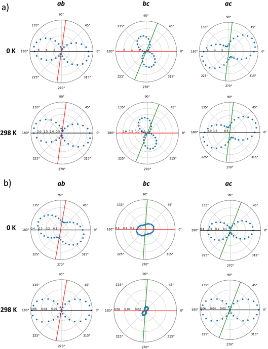
Hole mobilities were estimated by means of a homemade kinetic Monte Carlo code, which applies a Marcus-type rate for a list of preferential directions using a stochastic method (see Computational details and ESI†). First, the mobilities in the static crystals (0 K) of IDIDF and spiro-OMeTAD were calculated along the main crystallographic planes, according to the preferred conduction paths and the electronic couplings obtained for the most relevant dimers (V larger than 1 meV). Theoretical calculations predict a high level of anisotropy in the case of IDIDF, with a maximum μ value of 6.81, 0.51 and 2.94 cm2 V−1 s−1 in the a, b and c axes, respectively (Fig. 7a and Table S3†). Note that the maximum mobility does not fall exactly at the a axis due to the non-negligible contribution of the 2![[1 with combining macron]](https://www.rsc.org/images/entities/char_0031_0304.gif) 1 path. Similarly, the spherical spiro-OMeTAD also shows a high level of anisotropic hole conduction (Fig. 7b), as evidenced in previous reports.8,58 In this case, maximum μ values of 0.30, 0.12 and 0.09 cm2 V−1 s−1 are predicted in the a, b and c directions, respectively. These results for the static crystals indicate a significantly more efficient charge transport (ca. one order of magnitude) for planar IDIDF compared to spiro-OMeTAD.
1 path. Similarly, the spherical spiro-OMeTAD also shows a high level of anisotropic hole conduction (Fig. 7b), as evidenced in previous reports.8,58 In this case, maximum μ values of 0.30, 0.12 and 0.09 cm2 V−1 s−1 are predicted in the a, b and c directions, respectively. These results for the static crystals indicate a significantly more efficient charge transport (ca. one order of magnitude) for planar IDIDF compared to spiro-OMeTAD.
Dynamic effects were considered in the calculation of hole mobilities through the normal distributions of site energy differences and electronic couplings predicted along the molecular dynamics at room temperature (298 K). kMC simulations indicate a notable reduction in the charge transport by a factor of 3 in IDIDF and of 8 in the case of spiro-OMeTAD due to the finite temperature structural fluctuations. This leads to maximum μ values of 2.42 cm2 V−1 s−1 for IDIDF and 5.8 × 10⁻² cm2 V−1 s−1 for spiro-OMeTAD (Table 1). These values are in good correlation with the experimentally reported mobilities of 0.97 cm2 V−1 s−1 for the non-fluorinated analogue 4H4TIDID and 1.3 × 10⁻³ cm2 V−1 s−1 for spiro-OMeTAD in single-crystal devices.8,30 Whereas the mobility profiles along the three crystallographic planes are maintained in IDIDF upon considering dynamic disorder (Fig. 7a), the anisotropy in mobility is increased for spiro-OMeTAD, especially in the ab plane (Fig. 7b), as anticipated by the electronic coupling analysis.
| μ (IDIDF) | μ (spiro-OMeTAD) | |
|---|---|---|
| a Mean mobility values are presented. b A mobility of 0.97 cm2 V−1 s−1 was reported for the analogous non-fluorinated 4H4TIDID in a vacuum-deposited polycrystalline field-effect device.30 | ||
| Crystal (0 K) | 7.448 | 0.325 |
| Crystal (298 K) | 2.418 | 5.8 × 10⁻² |
| Amorphousa | 1.1 × 10⁻³ | 4.9 × 10⁻⁵ |
| Experimentalb | 1.7 × 10⁻³ (TF)29 | 4 × 10⁻⁵ (TF)59 |
| 1.3 × 10⁻³ (SC)8 | ||
3.3. Amorphous phase
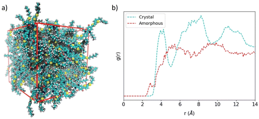
Perfect crystal morphology of HTMs leads to a theoretical upper bound mobility compared to the experimental data, allowing a fair comparison between theory and experiment only when single-crystal devices can be fabricated. In all other cases, a certain amount of paracrystallinity, semicrystallinity or even amorphousness are present in the HTM materials constituting the (opto)electronic device. In order to compare planar IDIDFvs. spherical spiro-OMeTAD in the lower-bound case scenario of having an amorphous material, we modelled large unit cells of up to 100 and 54 molecular structures for IDIDF and spiro-OMeTAD, respectively, where the molecules were placed randomly, and the size of the orthorhombic cell was varied until convergence. Then, a long molecular dynamics simulation of 200 ns in an NPT ensemble was performed.Representative snapshots of the amorphous HTMs are displayed in Fig. 8a for IDIDF and Fig. S7† for spiro-OMeTAD. The amorphous phase of the IDIDF HTM is characterized by a density of 1.11 g cm−3, slightly smaller than that of the perfect crystal (1.22 g cm−3). Unexpectedly, and despite its spherical-like shape, the amorphous phase of the highly isotropic spiro-OMeTAD is predicted with a converged density of 1.02 g cm−3, significantly smaller than that of the perfect crystal (1.25 g cm−3). This result may be explained by the unachieved intercalation between fluorene moieties of vicinal spiro-OMeTAD molecules in the amorphous phase, hindered by the bulky methoxyphenylamine groups. Radial distribution functions (g(r)) of the central molecule centroid with respect to the rest of the molecules evidence for IDIDF a shift to smaller distances (ca. 3 Å) of the shortest contacts compared to the crystal (3.5 Å) due to CH⋯π(indoloindole) interactions. Whereas in the perfect crystal a g(r) profile with three maxima is predicted at 4, 8 and 12 Å, the amorphous phase is predicted with a smoother g(r) practically stabilized at 5 Å (Fig. 8b). At this distance, 0.20 and 0.13 molecules are integrated for IDIDF crystal and amorphous phases, respectively, whereas 2.71 and 1.66 molecules are contained in a sphere of 10 Å. On the other hand, the crystal and amorphous phases of spiro-OMeTAD present a g(r) profile with a steep slope from 3.5 to 5 Å, and then a progressive increase up to ca. 11 Å (Fig. S7b†). These distances are correlated with the internal (the spirobifluorene core) and external (the whole molecule) radius calculated at 4.3 and 11.2 Å, respectively. In spiro-OMeTAD, 1.76 and 0.78 molecules are integrated at 10 Å for the crystal and the amorphous phase, respectively, which is in line with the lower density predicted for the latter.
Site energy differences and electronic coupling distributions were obtained for the nearest neighbours taking the central molecule as a reference in the amorphous phase of spiro-OMeTAD and IDIDF along the molecular dynamics simulations. In contrast to the dynamic disorder calculations, the long dynamics performed along 200 ns with geometry extractions each 1 ns inhibits vibrational resolution but instead we reach the time scale of conformational changes. Site energy differences nicely fit to a normal distribution with parameters [ΔĒ = −87; σ = 1881 meV] and [ΔĒ = −41, σ = 3232 meV] for spiro-OMeTAD and IDIDF, respectively. However, electronic couplings are highly centred at zero with a normal distribution that slightly overestimates the probability of having moderate V values (Fig. S8†): [![[V with combining macron]](https://www.rsc.org/images/entities/i_char_0056_0304.gif) = 0.03, σ = 1.62 meV] and [
= 0.03, σ = 1.62 meV] and [![[V with combining macron]](https://www.rsc.org/images/entities/i_char_0056_0304.gif) = 0.14, σ = 4.63 meV] for spiro-OMeTAD and IDIDF, respectively.
= 0.14, σ = 4.63 meV] for spiro-OMeTAD and IDIDF, respectively.
The stabilizing intermolecular NCI surfaces were integrated along the nearest-neighbour dimers extracted for the central molecule from the molecular dynamics of the amorphous phase, and compared with the value of the electronic coupling. Theoretical calculations indicate that there is not a clear correlation between the integrated volume of ρ associated to the attractive NCIs and V (Fig. 9). However, we predict a triangular profile in IDIDF (Fig. 9a), suggesting that NCI surfaces are important but not enough for predicting the electronic coupling trends (see, e.g., the NCI plots for characteristic dimers A, B and C in Fig. S9†). In contrast, spiro-OMeTAD does not present strong electronic couplings although large NCI surfaces are integrated in several dimers (Fig. 9b). Not only the proximity of the molecules but also the nature of this non-covalent interaction and the wavefunction symmetry must therefore be considered for predicting trends in V.
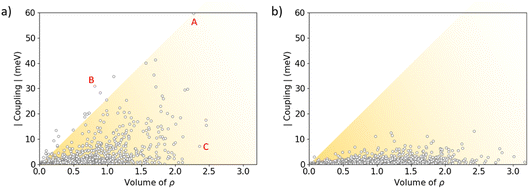 | ||
| Fig. 9 Absolute value of the electronic coupling vs. the integrated volume of ρ associated to the weakly stabilizing non-covalent interactions for IDIDF (a) and spiro-OMeTAD (b) first-nearest dimers as obtained during the NPT molecular dynamics in the amorphous phase. The representation of the RDG index for representative dimers A, B and C of IDIDF is displayed in Fig. S9.† | ||
Finally, hole mobilities were calculated from the kMC simulations and were compared with the previous data obtained for the static (0 K) and dynamic (298 K) crystals. Note that, in the amorphous phase, all the first nearest neighbours were considered in the normal distribution for site energy differences and electronic couplings (Fig. S8†). Theoretical calculations indicate an isotropic hole mobility profile in the amorphous phase of both spiro-OMeTAD and IDIDF, as expected; the average values of μ are summarized in Table 1. Compared to the crystal at 298 K, amorphousness leads to a decrease in hole transport of ca. 3 orders of magnitude for the two HTMs, with mean μ values of 1.1 × 10⁻³ and 4.9 × 10⁻⁵ cm2 V−1 s−1 for IDIDF and spiro-OMeTAD, respectively (Table 1). These data, which are in good accord with the experimentally reported mobilities of 1.7 × 10⁻³ and 4 × 10⁻⁵ cm2 V−1 s−1 for IDIDF and spiro-OMeTAD in thin-film devices,29,59 confirm the efficient charge transport of the indoloindole-based HTM for future applications in organic electronics and photovoltaics.
4. Conclusions
Herein, we report on the charge-transport properties of a novel hole-transporting material based on the indoloindole core with peripheral thiophene groups by using a multi-level theoretical approach. The impact of its anisotropic shape, the dynamic disorder and the morphology of the material are analysed in detail in comparison with the reference spiro-OMeTAD. First-principles theoretical calculations on IDIDF evidence a dispersive valence band maximum with small effective masses of the order of 1 m0, associated to the main transport direction characterized by the π–π stacking of the aromatic backbone. Extensive non-covalent interactions are calculated for the most-interacting dimers, but their nature and wavefunction symmetry considerations must be examined for electronic coupling predictive power. Molecular dynamics and kinetic Monte Carlo simulations were performed to unveil the impact of the dynamic disorder on the charge transport of our HTMs, leading to μ values of 2.42 cm2 V−1 s−1 for IDIDF and 5.8 × 10⁻² cm2 V−1 s−1 for spiro-OMeTAD (3 and 10 times lower mobilities, respectively, than in the static crystal), in good accord with reported experimental data. Despite the different molecular shape, we predict strong mobility anisotropy in both the spherical-like spiro-OMeTAD and the planar IDIDF, which is further enhanced upon dynamic structural fluctuations. Finally, amorphous phases were modelled with random distribution of the HTM molecules, leading to lower-bound mobilities of 1.1 × 10⁻³ and 4.9 × 10⁻⁵ cm2 V−1 s−1 for IDIDF and spiro-OMeTAD, respectively. These results confirm the excellent charge-transport properties of the indoloindole-based HTMs for future applications in organic electronics and photovoltaics.Author contributions
M. P.-E. and A. F.-A. performed all the theoretical calculations and postprocessing analyses. E. O., J. A., J. Cerdá, and J. Calbo supervised the work. All the authors contributed to writing the manuscript.Conflicts of interest
There are no conflicts to declare.Acknowledgements
This work has been supported by the Generalitat Valenciana (Project GV/2021/027) and the MCIN Spanish government (Unidad de Excelencia María de Maeztu CEX2019-000919-M, Project PID2020-119748GA-I00, and Project TED2021-131255B-C44 funded by MCIN/AEI/10.13039/501100011033 and by European Union NextGenerationEU/PRTR). M. P.-E. acknowledges PRE2021-097082 grant funded by MCIN/AEI and “ESF Investing in your future”. A. F.-A. thanks the CPI-22-471 project associated to CEX2019-000919-M.References
- Z. H. Bakr, Q. Wali, A. Fakharuddin, L. Schmidt-Mende, T. M. Brown and R. Jose, Nano Energy, 2017, 34, 271–305 CrossRef CAS.
- X. Yin, Z. Song, Z. Li and W. Tang, Energy Environ. Sci., 2020, 13, 4057–4086 RSC.
- A. Farokhi, H. Shahroosvand, G. D. Monache, M. Pilkington and M. K. Nazeeruddin, Chem. Soc. Rev., 2022, 51, 5974–6064 RSC.
- L. Nakka, Y. Cheng, A. G. Aberle and F. Lin, Adv. Energy Sustainability Res., 2022, 3, 2200045 CrossRef CAS.
- L. Calió, S. Kazim, M. Grätzel and S. Ahmad, Angew. Chem., Int. Ed., 2016, 55, 14522–14545 CrossRef.
- Y. Yao, C. Cheng, C. Zhang, H. Hu, K. Wang, S. De Wolf, Y. Yao, C. Cheng, C. Zhang, K. Wang, H. Hu and S. De Wolf, Adv. Mater., 2022, 34, 2203794 CrossRef CAS PubMed.
- H. Min, M. Kim, S. U. Lee, H. Kim, G. Kim, K. Choi, J. H. Lee and S. Il Seok, Science, 2019, 366, 749–753 CrossRef CAS PubMed.
- D. Shi, X. Qin, Y. Li, Y. He, C. Zhong, J. Pan, H. Dong, W. Xu, T. Li, W. Hu, J. L. Brédas and O. M. Bakr, Sci. Adv., 2016, 2, e15014 Search PubMed.
- T. Liu, K. Sun, R. He, Z. Zhang, W. Shen and M. Li, J. Phys. Chem. C, 2018, 122, 8804–8813 CrossRef CAS.
- Z. Hu, W. Fu, L. Yan, J. Miao, H. Yu, Y. He, O. Goto, H. Meng, H. Chen and W. Huang, Chem. Sci., 2016, 7, 5007–5012 RSC.
- Y. Wang, Z. Zhu, C.-C. Chueh, A. K.-Y. Jen, Y. Chi, Y. Wang, Y. Chi, Z. Zhu, C. Chueh and A. K.-Y. Jen, Adv. Energy Mater., 2017, 7, 1700823 CrossRef.
- X.-D. Zhu, X.-J. Ma, Y.-K. Wang, Y. Li, C.-H. Gao, Z.-K. Wang, Z.-Q. Jiang, L.-S. Liao, X.-D. Zhu, Y.-K. Wang, Y. Li, Z.-K. Wang, Z.-Q. Jiang, L.-S. Liao, X.-J. Ma and C.-H. Gao, Adv. Funct. Mater., 2019, 29, 1807094 CrossRef.
- Y.-K. Wang, Z.-C. Yuan, G.-Z. Shi, Y.-X. Li, Q. Li, F. Hui, B.-Q. Sun, Z.-Q. Jiang and L.-S. Liao, Adv. Funct. Mater., 2016, 26, 1375–1381 CrossRef CAS.
- B. Xu, D. Bi, Y. Hua, P. Liu, M. Cheng, M. Grätzel, L. Kloo, A. Hagfeldt and L. Sun, Energy Environ. Sci., 2016, 9, 873–877 RSC.
- B. Xu, J. Zhang, Y. Hua, P. Liu, L. Wang, C. Ruan, Y. Li, G. Boschloo, E. M. J. Johansson, L. Kloo, A. Hagfeldt, A. K. Y. Jen and L. Sun, Chem, 2017, 2, 676–687 CAS.
- D. Bi, B. Xu, P. Gao, L. Sun, M. Grätzel and A. Hagfeldt, Nano Energy, 2016, 23, 138–144 CrossRef CAS.
- M. Saliba, S. Orlandi, T. Matsui, S. Aghazada, M. Cavazzini, J. P. Correa-Baena, P. Gao, R. Scopelliti, E. Mosconi, K. H. Dahmen, F. De Angelis, A. Abate, A. Hagfeldt, G. Pozzi, M. Graetzel and M. K. Nazeeruddin, Nat. Energy, 2016, 1, 15017 CrossRef CAS.
- F. Zhang, Z. Wang, H. Zhu, N. Pellet, J. Luo, C. Yi, X. Liu, H. Liu, S. Wang, X. Li, Y. Xiao, S. M. Zakeeruddin, D. Bi and M. Grätzel, Nano Energy, 2017, 41, 469–475 CrossRef CAS.
- H. Li, K. Fu, A. Hagfeldt, M. Grätzel, S. G. Mhaisalkar, A. C. Grimsdale, H. Li, K. Fu, S. G. Mhaisalkar, A. C. Grimsdale, A. Hagfeldt and M. Grätzel, Angew. Chem., Int. Ed., 2014, 53, 4085–4088 CrossRef CAS PubMed.
- A. Molina-Ontoria, I. Zimmermann, I. Garcia-Benito, P. Gratia, C. Roldán-Carmona, S. Aghazada, M. Graetzel, M. K. Nazeeruddin and N. Martín, Angew. Chem., Int. Ed., 2016, 55, 6270–6274 CrossRef CAS.
- K. Rakstys, A. Abate, M. I. Dar, P. Gao, V. Jankauskas, G. Jacopin, E. Kamarauskas, S. Kazim, S. Ahmad, M. Grätzel and M. K. Nazeeruddin, J. Am. Chem. Soc., 2015, 137, 16172–16178 CrossRef CAS.
- H. Nishimura, N. Ishida, A. Shimazaki, A. Wakamiya, A. Saeki, L. T. Scott and Y. Murata, J. Am. Chem. Soc., 2015, 137, 15656–15659 CrossRef CAS PubMed.
- J. Liu, Y. Wu, C. Qin, X. Yang, T. Yasuda, A. Islam, K. Zhang, W. Peng, W. Chen and L. Han, Energy Environ. Sci., 2014, 7, 2963–2967 RSC.
- P. Gratia, A. Magomedov, T. Malinauskas, M. Daskeviciene, A. Abate, S. Ahmad, M. Grätzel, V. Getautis and M. K. Nazeeruddin, Angew. Chem., Int. Ed., 2015, 54, 11409–11413 CrossRef CAS PubMed.
- B. Xu, E. Sheibani, P. Liu, J. Zhang, H. Tian, N. Vlachopoulos, G. Boschloo, L. Kloo, A. Hagfeldt, L. Sun, B. Xu, E. Sheibani, H. Tian, L. Sun, P. Liu, L. Kloo, J. Zhang, N. Vlachopoulos, G. Boschloo and A. Hagfeldt, Adv. Mater., 2014, 26, 6629–6634 CrossRef CAS.
- X. Ding, C. Chen, L. Sun, H. Li, H. Chen, J. Su, H. Li, H. Li, L. Xu and M. Cheng, J. Mater. Chem. A, 2019, 7, 9510–9516 RSC.
- D. Luo, W. Yang, Z. Wang, A. Sadhanala, Q. Hu, R. Su, R. Shivanna, G. F. Trindade, J. F. Watts, Z. Xu, T. Liu, K. Chen, F. Ye, P. Wu, L. Zhao, J. Wu, Y. Tu, Y. Zhang, X. Yang, W. Zhang, R. H. Friend, Q. Gong, H. J. Snaith and R. Zhu, Science, 2018, 360, 1442–1446 CrossRef CAS PubMed.
- E. H. Jung, N. J. Jeon, E. Y. Park, C. S. Moon, T. J. Shin, T. Y. Yang, J. H. Noh and J. Seo, Nature, 2019, 567, 511–515 CrossRef CAS.
- I. Cho, N. J. Jeon, O. K. Kwon, D. W. Kim, E. H. Jung, J. H. Noh, J. Seo, S. Il Seok and S. Y. Park, Chem. Sci., 2017, 8, 734–741 RSC.
- I. Cho, S. K. Park, B. Kang, J. W. Chung, J. H. Kim, K. Cho and S. Y. Park, Adv. Funct. Mater., 2016, 26, 2966–2973 CrossRef CAS.
- D. W. Kim, K. H. Choi, S. H. Hong, H. S. Kang, J. E. Kwon, S. Park, B. K. An and S. Y. Park, Adv. Energy Mater., 2023, 13, 2300219 CrossRef CAS.
- Y. Li, H. Li, C. Zhong, G. Sini and J. L. Brédas, npj Flexible Electron., 2017, 1, 2 CrossRef.
- I. Yavuz and K. N. Houk, J. Phys. Chem. C, 2017, 121, 993–999 CrossRef CAS.
- D. Alberga, A. Perrier, I. Ciofini, G. F. Mangiatordi, G. Lattanzi and C. Adamo, Phys. Chem. Chem. Phys., 2015, 17, 18742–18750 RSC.
- T. Liu, K. Sun, R. He, Z. Zhang, W. Shen and M. Li, J. Phys. Chem. C, 2018, 122, 8804–8813 CrossRef CAS.
- A. T. Murray, J. M. Frost, C. H. Hendon, C. D. Molloy, D. R. Carbery and A. Walsh, Chem. Commun., 2015, 51, 8935–8938 RSC.
- H. Y. Li, J.-L. Brédas, S. N. Tessler and M. Zisapel, Adv. Funct. Mater., 2018, 28, 1803096 CrossRef.
- M. O. Yildirim, E. C. Gok Yildirim, E. Eren, P. Huang, M. P. U. Haris, S. Kazim, J. Vanschoren, A. Uygun Oksuz and S. Ahmad, Energy Technol., 2023, 11, 2200980 CrossRef CAS.
- M. Del Cueto, C. Rawski-Furman, J. Aragó, E. Ortí and A. Troisi, J. Phys. Chem. C, 2022, 126, 13053–13061 CrossRef CAS.
- J. P. Perdew, A. Ruzsinszky, G. I. Csonka, O. A. Vydrov, G. E. Scuseria, L. A. Constantin, X. Zhou and K. Burke, Phys. Rev. Lett., 2008, 100, 136406 CrossRef.
- V. Blum, R. Gehrke, F. Hanke, P. Havu, V. Havu, X. Ren, K. Reuter and M. Scheffler, Comput. Phys. Commun., 2009, 180, 2175–2196 CrossRef CAS.
- L. D. Whalley, J. Open Source Softw., 2018, 3, 797 CrossRef.
- K. Momma and F. Izumi, J. Appl. Crystallogr., 2011, 44, 1272–1276 CrossRef CAS.
- Chemcraft – graphical software for visualization of quantum chemistry computations, version 1.8, build 654, https://www.chemcraftprog.com Search PubMed.
- J. Contreras-García, E. R. Johnson, S. Keinan, R. Chaudret, J. P. Piquemal, D. N. Beratan and W. Yang, J. Chem. Theory Comput., 2011, 7, 625–632 CrossRef PubMed.
- D. P. McMahon and A. Troisi, J. Phys. Chem. Lett., 2010, 1, 941–946 CrossRef CAS.
- V. Lemaur, D. A. Da Silva Filho, V. Coropceanu, M. Lehmann, Y. Geerts, J. Piris, M. G. Debije, A. M. Van De Craats, K. Senthilkumar, L. D. A. Siebbeles, J. M. Warman, J. L. Brédas and J. Cornil, J. Am. Chem. Soc., 2004, 126, 3271–3279 CrossRef CAS PubMed.
- A. D. Boese and J. M. L. Martin, J. Chem. Phys., 2004, 121, 3405–3416 CrossRef CAS PubMed.
- T. Körzdörfer and J. L. Brédas, Acc. Chem. Res., 2014, 47, 3284–3291 CrossRef.
- B. Baumeier, J. Kirkpatrick and D. Andrienko, Phys. Chem. Chem. Phys., 2010, 12, 11103–11113 RSC.
- J. C. Phillips, D. J. Hardy, J. D. C. Maia, J. E. Stone, J. V. Ribeiro, R. C. Bernardi, R. Buch, G. Fiorin, J. Hénin, W. Jiang, R. McGreevy, M. C. R. Melo, B. K. Radak, R. D. Skeel, A. Singharoy, Y. Wang, B. Roux, A. Aksimentiev, Z. Luthey-Schulten, L. V. Kalé, K. Schulten, C. Chipot and E. Tajkhorshid, J. Chem. Phys., 2020, 153, 44130 CrossRef CAS PubMed.
- S. Jo, T. Kim, V. G. Iyer and W. Im, J. Comput. Chem., 2008, 29, 1859–1865 CrossRef CAS PubMed.
- D. T. Gillespie, J. Comput. Phys., 1976, 22, 403–434 CrossRef CAS.
- J. D. Hunter, Comput. Sci. Eng., 2007, 9, 90–95 Search PubMed.
- L. Martinez, R. Andrade, E. G. Birgin and J. M. Martínez, J. Comput. Chem., 2009, 30, 2157–2164 CrossRef CAS.
- J. M. Martínez and L. Martínez, J. Comput. Chem., 2003, 24, 819–825 CrossRef PubMed.
- A. Troisi, Chem. Soc. Rev., 2011, 40, 2347–2358 RSC.
- G. Meng, Y. Shi, X. Song, M. Ji, Y. Xue and C. Hao, Curr. Appl. Phys., 2017, 17, 1316–1322 CrossRef.
- T. Leijtens, I. K. Ding, T. Giovenzana, J. T. Bloking, M. D. McGehee and A. Sellinger, ACS Nano, 2012, 6, 1455–1462 CrossRef CAS PubMed.
Footnotes |
| † Electronic supplementary information (ESI) available. See DOI: https://doi.org/10.1039/d3fd00144j |
| ‡ These authors contributed equally. |
| This journal is © The Royal Society of Chemistry 2024 |

