 Open Access Article
Green energy driven methane conversion under mild conditions
Jiakang
You†
,
Yifan
Bao†
,
Yanzhao
Zhang
,
Muxina
Konarova
 ,
Zhiliang
Wang
 * and
Lianzhou
Wang
 *
*
Nanomaterials Centre, School of Chemical Engineering, Australian Institute for Bioengineering and Nanotechnology, The University of Queensland, St Lucia, Queensland 4072, Australia. E-mail: zhiliang.wang@uq.edu.au; l.wang@uq.edu.au
First published on 11th September 2024
Abstract
Methane is a critical energy resource but also a potent greenhouse gas, significantly contributing to global warming. To mitigate the negative effect of methane, it is meaningful to explore an effective methane conversion process motivated with green energy such as green electricity and sunlight. The selectivity and production rate are the key criteria in methane conversion. This review provides a comprehensive overview of recent efforts and understanding in methane conversion to valuable products, including oxygenates and hydrocarbons, by taking advantage of electrocatalysis and photocatalysis. The review begins with a general understanding of C–H bond activation mechanisms. It then focuses on electrocatalytic methane conversion (EMC) with an emphasis on catalyst design for oxygenate production, and photocatalytic methane conversion (PMC) with a particular focus on hydrocarbon production, especially ethylene (C2H4), due to the differences in oxygen sources between the two systems. An in-depth understanding of EMC and PMC mechanisms is also discussed to provide insights for improved catalyst design aimed at selective product generation. Finally, successful catalyst designs for EMC and PMC are summarized to identify challenges in achieving highly efficient and selective production of value-added chemicals and to offer clear guidance for future research efforts in green methane conversion.
Broader contextMethane's greenhouse effect has been shadowed by its significance in powering our society. With the carbon tax being implemented globally, methane emission becomes an emerging issue. The advances in solar energy utilization, such as solar-to-electricity and solar-to-chemical conversions, provide a green and sustainable pathway to address the methane emission issue by converting methane into valuable products under mild conditions. In order to achieve good selectivity and high production in methane conversion, different methods are applied, including electrocatalytic methane conversion (EMC) and photocatalytic methane conversion (PMC). This review will summarize the recent progress in EMC for oxygenate generation and PMC for hydrocarbon generation with the understanding about the C–H bond activation. This effort aims to shed light on innovations in methane management through solar energy. |
1 Introduction
Methane (CH4) has significantly contributed to global warming since the Industrial Revolution, with a global warming potential 84 times greater than that generated by carbon dioxide over 20 years and 28 times greater over a century.1,2 In 2021, global methane concentrations reached 1896.7 ppb, 2.62 times higher than pre-industrial levels (Fig. 1a).3 Currently, 580 Mt of methane is released into the atmosphere annually, with 60% of these emissions being anthropogenic. Agriculture accounts for 24% of total emissions, followed by fossil fuel utilization at 23%, largely from the generation of associated natural gas (Fig. 1b).1,2,4 Flaring methane during oil production alone releases around 140 billion cubic meters of associated natural gas each year, equivalent to approximately 3.5% of the annual natural gas production in 2020.5,6 With growing pressure to reduce carbon emissions and the commitment to achieve net zero scenario, there is an urgent need to mitigate the methane emission issue.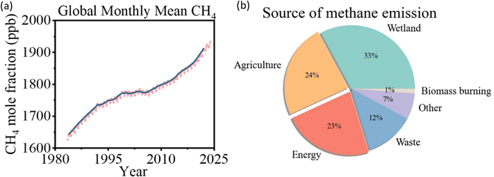 | ||
| Fig. 1 (a) Global averaged atmospheric methane, data from the National Oceanic and Atmospheric Administration, 2022.3 (b) Source of methane emission, data from the International Energy Agency, 2022.1 | ||
Besides its environmental impact, methane is also an important industrial C1 building block for many chemicals.7 Current industrial processes for methane conversion require two major steps with intensive energy consumption and carbon footprint. Generally, steam methane reforming is applied to produce syngas, a mixture of hydrogen and carbon monoxide,7 for many synthesis processes including Fischer–Tropsch synthesis for hydrocarbons, and Oxo-process for oxygenates.8 The conversion of methane into syngas is a highly endothermic reaction (ΔH = +206.2 kJ mol−1), which makes the reaction process require high thermal energy input and maintain a temperature above 700 °C.7 In pursuing sustainable society development and green chemical engineering, it is significant to explore direct conversions of methane into desirable products via a mild process.
Besides thermal energy, the photons and electrons can also activate methane as shown in Fig. 2a, emerging as increasingly popular fields of research since the beginning of this millennium (Fig. 2b).9–11 In a thermocatalytic process, heat input is to activate the catalyst surface and methane molecules, but the low thermal utilization efficiency significantly limits the overall conversion process. In comparison, electricity and solar energy are high-grade energy which can be used as the driving force to overcome the methane activation barrier, therefore the electrocatalytic and photocatalytic methane conversion can be effectively processed at room temperature. In particular, electrocatalytic methane conversion (EMC) studies focus on the partial oxidation of methane for oxygenates due to the aqueous environment, whereas most photocatalytic methane conversion (PMC) can achieve methane coupling for high-carbon product generation.12–14
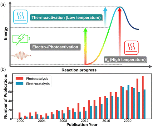 | ||
| Fig. 2 (a) Energy diagram for low-temperature methane conversion through thermal-, electro- and photocatalysis. Reproduced with permission.7 Copyright 2019, Elsevier. (b) Number of publications that include “Methane” and “Electro”/“Photo” according to the Web of Science (as on 30 August 2024). | ||
In the presence of oxygen, methane conversion will undergo a downhill reaction pathway with a negative enthalpy under standard conditions (ΔH298, reactions (1)–(5)).7 Particularly for methanol production viareaction (1), it can be achieved via a simple one-step reaction with a ΔH of −126 kJ mol−1.15 Compared to the conventional coal-based methanol production process, the methane partial oxidation represents a tidy and atomic economic reaction pathway. However, these oxygenated products are hard to preserve in the reaction environment as overoxidation of methane into carbon monoxide or carbon dioxide is much more favourable as shown in reactions (3) and (4).16 Methane coupling can also be expected viareaction (5) through the oxidative coupling of methane (OCM). Meanwhile, methane coupling can also be achieved in a non-oxidative procedure (NOCM), but with significantly higher ΔH as demonstrated in reaction (6).17 As a comparison between the OCM and NOCM processes, the OCM shows a faster reaction rate but at the risk of deep oxidation of the products, while NOCM gives much higher selectivity but at the cost of a slow reaction rate and coke formation.7,17,18
 | (1) |
 | (2) |
 | (3) |
 | (4) |
 | (5) |
 | (6) |
In this review, we focus on the cutting-edge advancements in methane conversion under mild conditions, particularly through EMC and PMC. The discussion includes the activation of the C–H bond and the various reaction pathways. By comprehensively revisiting catalyst design for EMC and PMC processes, we illustrate how the oxygen source influences product selectivity, and the challenges associated with improving production rates and selectivity. Towards the conclusion, we provide an outlook on these advancements and outline potential research directions for further development in both EMC and PMC.
2 Methane C–H bond dissociation
Methane has a very stable, highly symmetric tetrahedron structure, which makes it have not only low polarization but also extremely high bonding energy of 439 kJ mol−1.7 These features lead to harsh kinetics with low yield and poor selectivity for direct methane conversion. The biggest challenge of methane conversion lies in dissociating the C–H bonds of methane molecules, which is regarded as the holy grail of chemical reactions. Especially after the first C–H bond dissociation, the symmetry of CH4 will be broken down, which will trigger the following C–H bond activation. The dissociation pathways can be classified into deprotonation and dehydrogenation (Fig. 3) according to the formal oxidation state (FOS) of the central carbon.26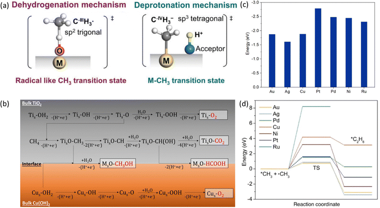 | ||
| Fig. 3 (a) Dehydrogenation and deprotonation mechanisms in first C–H bond dissociation. Reproduced with permission.26 Copyright 2020, Wiley-VCH. (b) Control of sequential C–H cleavage of the CH4 molecule at the interface between TiO2 and Cu(OH)2. Reproduced with permission.27 Copyright 2022 American Chemical Society. (c) Adsorption energy of *CH3 on the surface of different metals. (d) Transition state energies for *CH3 coupling reaction on the surface of different metals. Reproduced with permission.28 Copyright 2023, Wiley-VCH. | ||
The dehydrogenation process refers to the detachment of one hydrogen atom (that is one proton with one electron) from methane, resulting in the formation of a methyl radical (˙CH3).29 Oxygen can be applied as the hydrogen acceptor to form a hydroxide radical (˙OH). Deprotonation of methane is the removal of a proton and generation of a methenium ion (CH3−). It will result in the carbon maintaining its FOS at –IV with a tetrahedral geometry with sp3 hybridization, which will coordinate with the active site to form a metal–carbon σ bond as shown in Fig. 3.26,30–32 In contrast to the deprotonation, methyl radicals generated from the dehydrogenation mechanism result in the central carbon's FOS changing from –IV to –III with a trigonal-like sp2 hybridisation. It has weak interaction with the catalyst active sites as shown in Fig. 3.26 From the above discussion, deprotonation of methane is an acid–base reaction due to the proton participation, which is in line with the observation that the deprotonation process usually takes place in highly polar solvents such as water and high concentration acids within homogeneous systems.30
To distinguish these two mechanisms, the reaction energy profile by two pathways needs to be compared which can be clarified by the active oxygen species involved in the reaction. The active oxygen species can be electrophilic (e.g., O−, O2−) or nucleophilic (e.g., O2−).33 The dehydrogenation of methane involves electron-deficient oxygen species including O−, O2− from strong oxidants such as O2 and N2O, while methane C–H bond deprotonation generally involves with electro-saturated oxygen species (O2−) as proton acceptors.34 As a result, dehydrogenation is usually accompanied by strong oxidizing catalysts such as metal oxides and metal oxyhydroxides, and deprotonation requires metal or metal complexes with low oxidation states together with proton acceptors.34
After the first C–H bond dissociation in methane, the remaining C–H bonds become vulnerable to further dissociation in both EMC and PMC. To prevent this sequential dissociation, the *CH3 groups needs to be removed from the catalytic surfaces. The addition of cocatalysts can provide an interface that inhibits further dissociation. For example, CH4 suffers from severe over-oxidation to CO2 on a bare TiO2 surface. With the addition of Cu(OH)2 as a cocatalyst, it can provide additional reactive oxygen species (ROS) which can bind with *CH3 to generate methanol preventing further C–H cleavage (Fig. 3b).27 Besides ROS, *CH3 can also go through a coupling process to form higher hydrocarbons on the metallic cocatalysts with a stronger adsorption energy of *CH3 than it on metal oxides (Fig. 3c). Regarding C–C coupling, different metals exhibit varying behaviours due to differences in transition state energies, as shown in Fig. 3d.28 These variations can serve as a selection criterion for the design of efficient catalysts for CH4 coupling.
To understand the catalytic mechanism, different in situ characterization methods, e.g., Raman spectroscopy, infrared Microscopy (IR), X-ray absorption spectroscopy (XAS), and electron paramagnetic resonance (EPR), can be employed together with theoretical calculations to confirm the reaction route. In the following sections, we will introduce how these different mechanisms can be applied in EMC and PMC investigations.
3 Electrocatalytic methane conversion
3.1 Mechanisms and recent advances
EMC represents a process to overcome the methane activation energy with external electric potential.35 Depending on the activation or reaction sites, methane activation can occur either on the electrode surfaces (i.e., direct methane activation, Fig. 4a) or within the bulk liquid (i.e., indirect activation, Fig. 4b). For indirect activation, it involves the generation of highly oxidative species in the bulk electrolyte, which will be consumed in the following methane oxidation process.15 The applied potential plays a key role in controlling the reaction rate. As shown in Fig. 4c, under applied potential (noted with overpotential, η), the methane adsorbed on electrodes can be significantly activated, leading to a much lower energy barrier (ΔGF° − αzFη) compared to the conventional thermocatalytic process. Meanwhile, the applied potential will also significantly reduce the free energy of the products within the reaction environment, as a result of which the EMC will encounter a much stronger driving force under applied bias.15 Moreover, the applied potential can be precisely controlled, leading to the adjustment of both activity and selectivity of the EMC process.19 All these features make EMC a promising approach for methane conversion.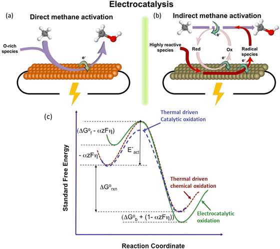 | ||
| Fig. 4 Schematic illustration of (a) direct electrocatalytic methane activation, and (b) indirect electrocatalytic activation. Reproduced with permission.15 Copyright 2021, Elsevier. (c) Effects of overpotential on reaction energy profile. Reproduced with permission.19 Copyright 2016, Elsevier. | ||
In a typical EMC process under mild conditions (<50 °C), oxygenated species such as C1–C3 alcohols and carboxylic acids are the main products. During EMC, the active oxygen species surface coverage is significant for methane activation and substantially affect the final product selectivity and conversion rate.36–38 In heterogeneous EMC, water from the liquid electrolyte is the source for active oxygen species generation towards methane conversion products. Meanwhile, it will compete with the water oxidation for the oxygen evolution reaction (OER). Therefore, many strategies have been applied to facilitate EMC while suppressing the OER in electrocatalysis by materials engineering, electrolyte engineering, and/or more easily, precise control of applied bias. By contrast, homogeneous EMC provided an ultimate solution to suppress the OER by utilizing concentrated acidic electrolyte, which avoids aqueous content. These strategies are incorporated into recent advances of EMC, a summary of which is presented based on heterogeneous and homogeneous systems in Table 1.
| System | Catalyst | Reaction conditions | Electrolyte | Performance | Ref. |
|---|---|---|---|---|---|
| If not stated, operation conditions are under ambient conditions of 25 °C, 1 bar.a NT: nanotube.b SHE: standard hydrogen electrode.c NS: nanosheet.d RHE: reversible hydrogen electrode.e SAC: single atom catalyst.f MOF: metal–organic framework.g a-KB: acid-treated Ketjen Black.h SSE: silver sulphate electrode.i 20% oleum contains 20% SO3 and 80% H2SO4 by weight.j TOF: turnover frequency.k SCE: saturated calomel electrode.l MSE: mercurous sulphate electrode. | |||||
| Heterogeneous | NiO/ZrO2 | 40 °C | 1.0 M Na2CO3 + DMF soaked AM-PAD anion exchange membrane | J = 21 mA cm−2 | 39 |
| 2.0 V | |||||
| ZrO2/Co3O4 | 2.0 V vs. Pt | 0.5 M Na2CO3 | J < 10 mA cm−2 | 40 | |
| 1-Propanol: 111.3 μmol gcat−1 h−1 | |||||
| 2-Propanol: 109.6 μmol gcat−1 h−1 | |||||
| Production efficiency 60% | |||||
| ZrO2/NiCo2O4 | 2.0 V vs. Pt | 0.5 M Na2CO3 | Conversion efficiency: 47.5% | 41 | |
| Propionic acid: 1173 μmol gcat−1 h−1 | |||||
| Propionic acid selectivity: 65% | |||||
| Co3O4/ZrO2 NTa | 2.0 V vs. SHEb | 0.5 M Na2CO3 | 1-Propanol: 2681 μmol gcat−1 h−1 | 42 | |
| 2-Propanol: 1395 μmol gcat−1 h−1 | |||||
| Product selectivity: 91.98% | |||||
| CuO/CeO2 | 1.5 V, 10 bar | 0.5 M Na2CO3 | Methanol: 752.9 μmol gcat−1 h−1 | 43 | |
| Methanol selectivity: 79% | |||||
| Methanol: 1832.2 μmol gcat−1 h−1 | |||||
| Fe3Ni7(OH)x NSc | 1.46 V vs. RHEd | 0.1 M NaOH | TOF = 936 | 44 | |
| Ethanol: 9090 μmol gcat−1 h−1 | |||||
| faradaic efficiency: 87% | |||||
| NiO/Ni foam | 1.4 V vs. RHE | 0.1 M NaOH | Current efficiency = ∼100% | 45 | |
| Ethanol selectivity: 89% | |||||
| Ethanol: 25 μmol gcat−1 h−1 | |||||
| Methanol selectivity: 10% | |||||
| Methanol: 7.4 μmol gcat−1 h−1 | |||||
| Fe–N–C SACe | 1.6 V vs. RHE | 0.1 M KOH | Ethanol batch: 4668.3 μmol gcat−1 h−1 | 37 | |
Ethanol flow: 11![[thin space (1/6-em)]](https://www.rsc.org/images/entities/char_2009.gif) 480.6 μmol gcat−1 h−1 480.6 μmol gcat−1 h−1 |
|||||
| Ethanol selectivity: 85% | |||||
| Methanol selectivity: 15% | |||||
| Rh/ZnO NS | 2.2 V vs. RHE | 0.1 M KOH | Production rate: 789 μmol gcat−1 h−1 | 46 | |
| Ethanol selectivity: 85% | |||||
| Mg-MOF-74 f | 1.6 V vs. RHE | 1 M KOH | Production rate: 127 μmol gcat−1 h−1 | 47 | |
| Total FE: 10.9% | |||||
| a-KBg | 0 V vs. RHE | 0.05 M H2SO4 | Production rate: 1680 μmol gcat−1 h−1 | 48 | |
| Formic acid selectivity: 80.7% | |||||
| Ag, FeII | 0.12 V vs. RHE | 0.1 M HClO4 | Production rate: 11.5 mmol gFe−1 h−1 | 49 | |
| Homogeneous | Pd2III,III | 140 °C | 20% oleumi | TOFj = 2000 | 50 |
| 34 bar | |||||
| 2.0 V vs. SSEh | TOF = 2000 | ||||
| RhIII | −1.4 V vs. SCEk | 0.1 M TBACLO4 in 1,2 DFB | TOF = 2159 | 51 | |
| V2–oxo | 2.255 V vs. SCE | 98% H2SO4 | TOF = 483 | 52 | |
| 3 bar | TOF = 1336 | ||||
| AgII | 6 bar | 98% H2SO4 | TOF = 2800 | 53 | |
| 1.737 V vs. MSEl | |||||
3.2 Heterogeneous catalysts
Heterogeneous EMC originates from solid oxide fuel cell research using methane as a fuel. Generally, a methane conversion catalyst is directly deposited on a solid oxide electrolyte (SOE) as the ion conductor and thus results in an effective methane conversion. It can provide fast mass transfer of methane onto the catalytic surfaces with a gas diffusion layer. However, the activation of the SOE usually requires high temperature (over 200 °C), which is a bottleneck for the wide application of this method. Many efforts have been evoked to break this limitation with the innovation in SOE and development in efficient electrocatalysts, which meanwhile improved the selectivity towards specific product of interest.54–59 The very first EMC at nearly ambient temperature was performed on NiO/ZrO2 with the use of a carbonate anion exchange membrane, where the interaction between ZrO2 and CO32− provides the key oxygen species for the reaction.39 To make the reaction condition milder, studies are aimed at achieving ECM at room temperature with a liquid electrolyte. ZrO2 and CO32− have been employed in combination to provide active oxygen species facilitating EMC and it has been reported that ZrO2 anchored on oval-shaped cobalt(II, III) oxide (Co3O4) heterojunctions has supreme ability to react with CH4.40 Three-carbon (C3) species products are generated following a proposed mechanism in Fig. 5a. The methane C–H bond dissociation undergoes a dehydrogenation mechanism, which is either followed by nucleophilic addition to form 2-propanol or free radical addition to form 1-propanol.40 The following study uses bimetallic oxide NiCo2O4 to replace Co3O4 in a nanowire structure with similar heterojunctions between ZrO2 and reaches a 65% product selectivity towards propionic acid.41 By further applying morphology control over the ZrO2 substrate by forming a nanotube structure (Fig. 5b), the reaction rate is improved by 10-fold.40,42 Furthermore, CeO2 shows low oxygen vacancy formation energy, leading to the enhanced active oxygen species generation from CO32−. Therefore, CeO2-based materials were developed with monoclinic copper oxide (CuO), and the developed CeO2/CuO has achieved significant methanol production with high selectivity.43,60 | ||
| Fig. 5 (a) Nucleophilic addition reaction of methane to form 2-propanol and free radical addition reaction of methane with acetaldehyde to form 1-propanol. Reproduced with permission.40 Copyright 2017, Wiley-VCH. (b) Schematic illustration of the ZrO2 NT/Co3O4 synthesis procedure. Reproduced with permission.42 Copyright 2021, Elsevier. | ||
EMC can be promoted by surface active oxygen species from CO32− ions with the combination of material and electrolyte engineering. It is reported that the utilization of CO32− ions can circumvent the complete OER and maintain a high surface coverage of active oxygen.22 In addition to carbonate, alkaline electrolytes including sodium hydroxide (NaOH) and potassium hydroxide (KOH) are also employed in EMC systems together with accurate control of applied bias to generate active oxygen species. The potential-dependent reaction mechanism usually leaves a small potential window that can simultaneously generate and stably maintain active oxygen species on the catalytic surfaces. In addition, methane overoxidation into CO2 can also be prevented by adjusting the bias. This naturally makes accurate control of the applied bias on these catalytic surfaces crucial for achieving a high conversion of methane.
Taking the surface of a CoOx film as an example, the EMC process consists of 4 major steps, including oxyhydroxide (–OOH) formation, methanol production, overoxidation to carbon dioxide, and the OER, respectively.38 As shown in Fig. 6a, at potentials between 0.5 and 1.0 V vs. SHE, methane conversion into methanol is dominant, while above 1.0 V vs. SHE, the overoxidation of methane into carbon dioxide is preferred, whereas the OER, which competes with methane in reacting with OH*, occurs and dominates at potential greater than 1.28 V vs. SHE.38 Inspired by the above potential dependent reaction mechanism, iron-nickel hydroxide nanosheets (Fe3Ni7(OH)x) are developed, which can convert methane into ethanol at 1.46 V vs. RHE, where the nickel oxyhydroxide (NiOOH) generated from NiO is considered as the active phase for the EMC process as revealed by the increased oxidation peak of Ni(II) to Ni(III) transition.44,45
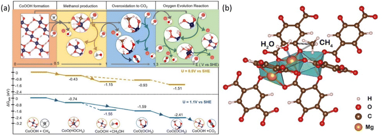 | ||
| Fig. 6 (a) The top panel shows the favoured reactions at certain electrochemical potential range evaluated at pH = 12. The bottom panel shows reaction energy diagram at U = 0.5 V vs. SHE and 1.1 V vs. SHE. Reproduced with permission.38 Copyright 2023, American Chemical Society. (b) Graphical illustration of the CH4 adsorption on Mg–oxo–Mg and H2O adsorption on Mg of Mg-MOF-74. Reproduced with permission.47 Copyright 2022, Elsevier. | ||
Accurate control of the applied bias on catalytic surfaces is crucial for achieving a high coverage of active oxygen species, given the potential-dependent OER process. Material engineering is employed to achieve a broad potential range that maximizes the generation of surface oxygen species without complete water oxidation via the OER pathway. For instance, on a Fe–N–C single-atom catalyst, active atomic oxygen can be stabilized even at relatively high potentials owing to its unique rate-limiting step in the OER.37 Following a similar principle, rhodium-doped zinc oxide nanosheets (Rh/ZnO NS) and magnesium-substituted metal organic frameworks (Mg-MOF-74) have also demonstrated promising selectivity for EMC.46,47 Another strategy to avoid complete oxidation of water is to perform EMC with alternative oxidative agent rather than surface active oxygen species. For instance, EMC can be coupled with the oxygen reduction reaction (ORR) on cathodes. Such a strategy is successful on acid-treated ketjen black (a-KB) carbon powder working as the cathode catalyst for in situ ORR generating hydrogen peroxide (H2O2) (Fig. 7a), which subsequently generates active oxygen species to facilitate the EMC process.48 The Fenton reaction for fast generating active oxygen species is then incorporated into such a system (Fig. 7b) with a silver foil cathode.49 For this ORR-induced EMC process, the cathode is not directly responsible for methane oxidation but generates active oxidative species reacting with methane molecules.
 | ||
| Fig. 7 (a) Schematic illustration of the reaction mechanism for direct POM with the in situ ORR. Reproduced with permission.48 Copyright 2023, Springer Nature. (b) Schematic illustration of Fenton reaction assisted POM with the in situ ORR. Reproduced with permission.49 Copyright 2024, American Chemical Society. | ||
3.3 Homogeneous electrocatalysts
In homogeneous EMC systems, the CH4 molecule is directly oxidized by the oxidative reagents produced on anodes.32 In these systems, highly oxidative intermediates will first be produced on anodes (e.g., Mn+2 in Fig. 8a), then the Mn+2 will oxidize methane molecules into methanol (Fig. 8a). In the presence of concentrated H2SO4, the electrophilic high valent metal ions can mediate methane conversion through a two-electron oxidation process into methyl esters, which can be protected from further being oxidized by the electron-withdrawing effect of the HSO4− groups. During these reactions, the capability for methane oxidation can be estimated by the redox potential of the metal ions (Fig. 8b).30,50 This strategy is usually performed in a non-aqueous electrolyte which wipes out the concern brought by the OER. Thus, the key research challenges in homogeneous EMC lie in the proper selection of redox couples for efficient methane conversion and stable redox loops.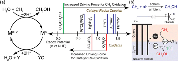 | ||
| Fig. 8 (a) Redox potentials of methane oxidation catalysts. (Left) Simplified catalytic cycle for electrophilic methane oxidation using a stoichiometric oxidant such as SO3 or O2. (Right) Estimated redox potentials of electrophilic methane functionalization catalysts/reagents. Reproduced with permission.50 Copyright 2017, American Chemical Society. (b) The proposed catalytic cycle of RhII functioning methane into methanol. Reproduced with permission.51 Copyright 2019, American Chemical Society. | ||
Redox couples including PdIII,III, AgI,II, V2–oxo, and RhII,III have been demonstrated to be efficient as homogeneous electrocatalysts (Table 1), in which AgI,II and V2–oxo show the benchmark high CH4 conversion rate. The V2–oxo dimer is synthesised by dissolving V2O5 in 98% H2SO4 and can achieve EMC at a TOF of 1336 h−1.52 The high efficiency of this catalyst is attributed to its extremely low activation energy of 10.8 ± 0.6 kcal mol−1 in methane functionalization.52 The rate-limiting step is then considered either the dissolution of methane or the one-electron oxidation of the V–oxo dimer.52 Another work on AgI, II achieved a TOF of 2800 h−1 in 3 h at ambient temperature. Moreover, one unique approach reported is by utilizing RhII tetramesitylporphyrin metalloradicals, which functionalised CH4via the oxidation of RhII to RhIII, as illustrated in Fig. 8b.
The EMC driven by a homogeneous process with different redox couples can avoid the OER process and achieve a fast CH4 oxidation. However, the utilized highly acidic electrolyte presents as a high-risk, which also makes the long-term stability a concern during operation. The efforts in homogenous EMC should be mainly devoted to lower the harshness of the reaction conditions. Despite these advances, EMC is hindered by its low efficiency because of the low solubility and widespread product distribution. Future development in this field necessitates a focus on the development of novel catalyst design, such as bifunctional electrocatalysts, to provide active sites for reactant adsorption and the dissociation of methane C–H bonds.
4 Photocatalytic methane coupling into ethylene
The electrocatalytic methane conversion generally requires a liquid phase electrolyte, which will lead to a significant mass diffusion issue at high current application. To overcome this issue, gaseous phase CH4 conversion is more applicable for high-rate methane conversion. Photocatalytic methane conversion (PMC) is considered the most cutting-edge strategy for high efficiency and green methane conversion. In the research community, some remarkable advances have been made in methane coupling to ethane. However, for the more promising product, ethylene, there has been no good summary in revisiting the reaction mechanism and photocatalyst design. In the following section, we will focus on the recent research progress on PMC for ethylene generation.4.1 Mechanisms and pathways
PMC offers a promising solution by harvesting the energy from sunlight using semiconductor materials.61 As shown in Fig. 9, under light irradiation with energy greater than the energy gap of the semiconductor, the electrons in the valence band (VB) will be excited to the conduction band (CB) leaving vacancies regarded as holes in the VB. The photogenerated electrons and holes will then transfer to the semiconductor surface and facilitate the redox reactions. To drive CH4 conversion, the position of the VB in the semiconductor should be more positive than the redox potential required for breaking C–H bonds (+2.06 V vs. SHE); however the position of the CB should be more negative than the redox potential required for reducing O2 in the OCM or the redox potential for H2 production for NOCM (0 V vs. SHE).23,62 Due to the abundance and eco-friendliness of photoenergy on Earth, this promising solution not only provides the potential to revolutionize ethylene production but also solves the increasing demand for cleaner and cost-effective methods in the industry.63During PMC, it is regarded that CH4 is first oxidized by photogenerated holes to form a methyl intermediate (*CH3) which then can be further coupled together to form C2 products (e.g., C2H6 and C2H4).11 Simultaneously, in photocatalytic NOCM (Fig. 9a), protons (H+) are formed and further reduced by photogenerated electrons producing hydrogen, whereas in photocatalytic OCM (Fig. 9a), O2 is reduced by photogenerated electrons together with protons to form water. Ethylene production can be achieved through two different possible pathways followed by the first C–H bond dissociation of methane as shown in Fig. 10.64 One pathway is that the *CH3 will first couple together to form C2H6 and then produce C2H4via a dehydrogenation process. Alternatively, the formed *CH3 will be further cleaved to form methylene intermediate (*CH2) for the coupling reaction for C2H4 generation. Despite the above assumptions, currently, there is still no consensus on the most plausible pathway for C2H4 generation. This reaction can be affected by multiple factors, such as photocatalyst design, cocatalyst loading, different oxidative agents for OCM, and reactor configuration. The following sections discuss how these factors affect the C2H4 production via PMC.
4.2 Semiconductor photocatalyst design
Semiconductors are essential components for absorbing light and producing photogenerated electron–hole pairs during PMC. Metal oxide semiconductors, such as TiO2, WO3, and ZnO, are widely used in photocatalytic methane conversion, due to the much positive position of O 2p orbitals (approximately at +3 V vs. SHE), which has a strong oxidation capability upon light irradiation to produce reactive oxygen species (ROS) (e.g., O− and O2−).65 These ROSs are highly active in cleaving the protons from the C–H bond in CH4via the electrophilic activation process. However, it is noteworthy mentioning that under a gaseous environment, the above redox potential may not be applicable, which is dedicated to the aqueous environment, and more investigations are required for clarifying the selection criteria for potential semiconductors. Table 2 summarizes the published works on photocatalytic coupling CH4 to C2H4.| Photocatalyst | Cocatalyst | C2H4 production rate (μmol g−1 h−1) | C2H4 selectivity | Reaction conditions | Ref. |
|---|---|---|---|---|---|
| Ga2O3-P | — | 0.005 | 2.8% | 300 W Xe lamp; 310 K; 3 h; 0.2 g catalyst; 200 μmol CH4 | 66 |
| Ce/SiO2 | — | 0.05 | 14.6% | 300 W Xe lamp; 310 K; 3 h; 0.2 g catalyst; 200 μmol CH4 | 67 |
| Ce/Al2O3 | — | 0.1 | 22.7% | 300 W Xe lamp; 310 K; 3 h; 0.2 g catalyst; 200 μmol CH4 | 67 |
| Ga3+-modified Titanosilicate (ETS-10) | — | 0.5 | 3.8% | 150 W high-pressure Hg lamp; 5 h; 0.2 g catalyst; 200 μmol CH4 | 68 |
| TiO2 nanotubes | — | 54.58 | 50.2% | 300 W Xe lamp; 4 h; 3 mg catalyst; 5 mL CH4 | 69 |
| ZnO | Au | Trace amount | N/A | 365 nm LED (PLS-LED100C); 4 h; 5 mg catalyst; CH4/O2 = 99/1, 56 mL gas | 28 |
| In2O3 | Ag | Trace amount | N/A | 300 W Xe lamp; 1 h; 20 mg catalyst; 175 mL CH4 | 70 |
| TiO2 (P25) | Pt | 1.11 | 2% | UV lamp (Philips, TUV 4W/G4 T5; wavelength at 254 nm); 6 h; 75 mg catalyst; 80 mL CH4 | 71 |
| TiO2 (PC-50) | Pt, CuOx | 2.4 | 2.1% | 40 W 365 nm LED; 100 mg catalyst; O2:CH4 = 1![[thin space (1/6-em)]](https://www.rsc.org/images/entities/char_2009.gif) : :![[thin space (1/6-em)]](https://www.rsc.org/images/entities/char_2009.gif) 400; GHSV = 2400 h−1; 10% CH4; Flow reactor 400; GHSV = 2400 h−1; 10% CH4; Flow reactor |
72 |
| ZnO | AuPd2.7 | 13.3 | 38.1% | 300 W Xe lamp; 8 h; 2 mg catalyst; 0.5 mL CH4 | 73 |
| WO3 | Pd5/Zn0.35 | 24 | 75.3% | 300 W Xe lamp; 2 h; 2 mg catalyst; 0.5 mL CH4 | 74 |
| ZnO/TiO2 | Au | 20 | 0.36% | 300 W Xe lamp; 20 mg catalyst; CH4/synthetic air (20 vol% O2/N2) = 69/1; Flowrate = 70 mL min−1; Flow reactor | 75 |
| Bi2NbO5F | Au2-Pd2 | 22.6 | 63% | 300 W Xe lamp; 2 h; 5 mg catalyst; 1 mL CH4 | 76 |
| TiO2 (P25) | Ag | 686 | 54.4% | Xe lamp (Power of 84.2 mW cm−2); 2 h; 100 mg catalyst; CO2/CH4/Ar = 7.5/7.5/85; 2 MPa | 77 |
| TiO2 (PC-50) | PdCu Nanoalloy | 60 | 1.25% | 40 W LED 365 nm; 50 mg catalyst; CH4/O2 = 114/1, 10% CH4 (Ar in Balance); GHSV = 342![[thin space (1/6-em)]](https://www.rsc.org/images/entities/char_2009.gif) 000 mL g−1 hour−1; Flow reactor 000 mL g−1 hour−1; Flow reactor |
78 |
| TiO2 | Sputtered Au | 140 | 0.5% | 100 W LED 365 nm; 20 mg catalyst; 320 mL min−1 CH4, 12 mL min−1 air; 393 K; Flow reactor | 79 |
| Carbon-doped ZnO | Au | 45.85 | 90.79% | 300 W Xe lamp; 3 h; 100 mg catalyst; 1.5% CH4 (Ar in balance), 500 mL gas | 80 |
| ZnO | Ag | 19.74 | 10.53% | 300 W Xe lamp; 0.5 g catalyst; 5% CH4 (N2 in balance); Flowrate = 10 mL min−1; Flow reactor | 81 |
| TiO2 | Au0.05–Pd0.05 | 794 | 12.11% | 300 W Xe lamp; 10 mg catalyst; moist CH4 70 mL min−1; Flow reactor | 82 |
| TiO2 | Pd | 22 | 2.4% | 300 W Xe lamp; 3 h; 3 mg catalyst; 30 mL CH4 | 83 |
In the early period, gallium oxide was researched as a photocatalyst for NOCM in which a little amount of C2H4 (0.005 μmol g−1 h−1) was observed with a carbon selectivity of only 2.8%.66 C2H4 was identified as an adsorbed product on the catalysts, which can only be obtained after desorbing at 300 °C. Similarly, using supported ceria photocatalysts (as shown in Fig. 11a with other lanthanoid elements), trace amounts of C2H4 production can be observed directly without the desorbing process, while the majority of the C2H4 product (0.1 μmol g−1 h−1) with 22.7% selectivity was obtained by thermal desorption on the low ceria loading samples.67 Attention should be paid to determine whether the source of the C2H4 product is from photocatalysis or thermal catalysis. It is claimed that the main species on the low-loading sample were Ce(III) oxide isolated monomers with high dispersity on the surface of the support (i.e., SiO2 and Al2O3) due to the quantum size effect. According to the photocatalytic performance and its methane quenching experiments, these highly dispersed Ce(III) species would act as the active sites for photocatalytic NOCM. Nevertheless, pure intrinsic semiconductors suffer from rapid recombination of photogenerated electron–hole pairs and insufficient active sites.
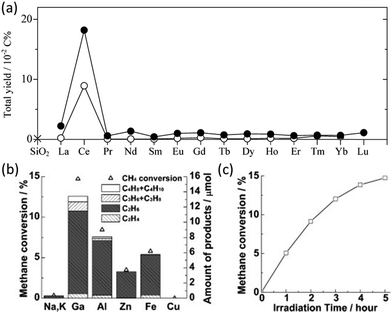 | ||
| Fig. 11 (a) Total hydrocarbon yield in photocatalytic NOCM over SiO2 (cross), lanthanoid elements (0.1 mol%) decorated SiO2 (open circles), and lanthanoid elements (2 mol%) decorated SiO2 (closed circles); Reproduced with permission.67 Copyright 2008, American Chemical Society; (b) Photocatalytic NOCM performance over ETS-10 doped with different metal ions; (c) Photocatalytic NOCM performance as a function of time over Ga-ETS-10. Reproduced with permission.68 Copyright 2012, Wiley-VCH. | ||
To avoid the charge recombination possibility and enhance the activation of C–H bonds, a doping strategy has been incorporated. A study focusing on titanosilicate (ETS-10) with a microporous structure containing titanate semiconductors surrounded by the SiO2 matrix used different metal ion dopants to enhance its photoactivity.68 Compared with the intrinsic EST-10, the metal-modified (i.e., Ga, Al, Zn, and Fe) EST-10 exhibited a dramatic enhancement on the photocatalytic NOCM performance due to the interaction of methane and the binary active species (i.e., dopant metal ions and photogenerated holes).84 Among them, Ga-modified EST-10 showed the best NOCM performance with almost 15% methane conversion rate (Fig. 11b and c) due to the strong C–H polarization ability.
In addition to metal doping, non-metal doping has been researched recently. Carbon-doped ZnO was constructed for efficient photocatalytic NOCM to C2H4 at a rate of 45.85 μmol g−1 h−1 with excellent selectivity of 90% for C2H4 production and stoichiometric H2 (88.07 μmol g−1 h−1). The carbon doping in ZnO was proven to improve the stability of lattice oxygen, light absorption, and CH4 activation.85 This photocatalyst can not only weaken excitonic confinement to enhance charge separation but also suppress the overoxidation of hydrocarbons.86 To achieve efficient C2H4 production, this photocatalyst generates Zn+–O− pairs to cleave C–H bonds, stabilizes the methoxy intermediate (*OCH3) for C–C coupling, and promotes the low-valence Zn generation for dehydrogenation of the formed ethoxy intermediate (*OC2H5) to produce C2H4.
Crystal facet engineering has also been proven to be a promising strategy to fine-tune the structure of the photocatalysts by exposing the highly active facets to optimize the performance.87–89 Furthermore, defect engineering provides an alternative way to boost the photocatalyst performance by extending the light absorption range, increasing the surface active sites, and stabilizing key intermediates for C–H cleavage.90 A recent study combined these two strategies (Fig. 12a) to construct oxygen vacancy self-doped single crystal-like TiO2 nanotubes (Vo-p-TNT) with preferential crystalline orientations (001).69 Through the modification of crystal facet and oxygen vacancy, this material achieved a C2H4 production rate of 54.58 μmol g−1 h−1 with 50.2% selectivity (Fig. 12b). Due to the coke deposition, the stability of this material was mediocre (Fig. 12c). The preferential crystal facet (001) was proved to improve the photogenerated charge separation and transfer, whereas the oxygen vacancy offers a significant number of unsaturated coordination sites for CH4 adsorption and acts as electron traps to avoid charge recombination. The synergistic effect of oxygen vacancy and (001) facets resulted in an effective pathway for electron transfer between the photocatalyst and the adsorbed CH4 molecule.91 The crystal facet engineering implemented on other photocatalysts (such as ZnO and WO3) rather than TiO2 requires exploration.
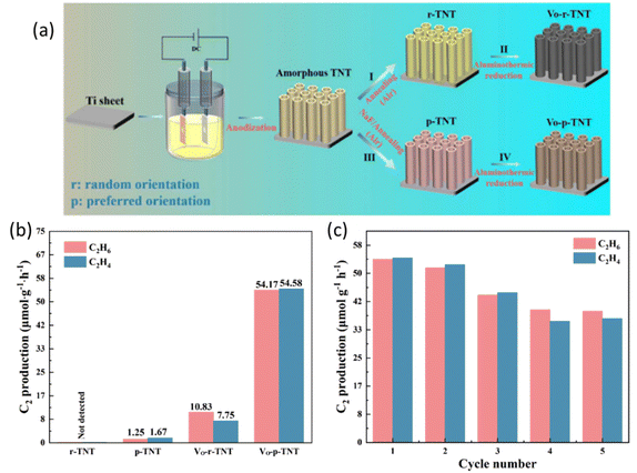 | ||
| Fig. 12 (a) Schematic representation of the preparation process for different types of TNT; (b) photocatalytic NOCM performance over different types of TNT; (c) cyclic photocatalytic NOCM tests of Vo-p-TNT. Reproduced with permission.69 Copyright 2023, Tsinghua University Press Ltd. | ||
4.3 Cocatalyst loading
Loading cocatalysts is an efficient way to improve the photocatalytic performance.92 In a PMC system, the cocatalysts have several advantages, including (1) improving charge separation and transfer efficiency; (2) providing active sites for CH4 activation; (3) enhancing the stability of photocatalysts; (4) controlling the selectivity of desired products.93 Currently, the research on cocatalysts in the field of PMC majorly focuses on noble metals, e.g., Pt, Ag, Pd, and Au.24During PMC, CH4 will firstly be oxidized to *CH3 by photogenerated charges. With the loading of metal cocatalysts, the formed *CH3 can be trapped on the metal surface from the photocatalyst and further couple together to produce C2 products as shown in Fig. 13a. Various metallic cocatalysts (e.g., Au, Ag, Pd, Cu, Ni, Ru, and Pt) loaded on the surface of the ZnO photocatalyst via the chemical reduction method have been studied for PMC (Fig. 13b).28 Although the major product was C2H6 with C2H4 production as a minor reaction, the mechanistic study presented the uniqueness of Au in photocatalytic OCM compared with other metallic cocatalysts. The photogenerated *CH3 tended to be coupled on Au but overoxidized on other metals due to the small coupling energy barriers (0.74 eV) on Au and the strong d-σ hybridization energy state (−5.63 eV) between Au and *CH3, which is below the Fermi level of Au.94 Moreover, Au loaded on photocatalysts can promote the adsorption and activation of O2 and increase the number of active photogenerated holes.
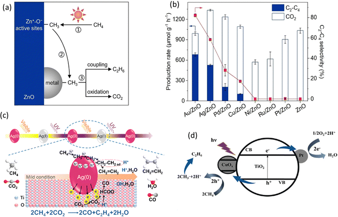 | ||
| Fig. 13 (a) Schematic representation of the photocatalytic OCM reaction mechanism on metal/ZnO; (b) Photocatalytic OCM performance over ZnO and different metal loaded ZnO. Reproduced with permission.28 Copyright 2023, Wiley-VCH. (c) Schematic representation of the photocatalytic CH4 and CO2 to C2H4 reaction mechanism over Ag/TiO2; Reproduced with permission.77 Copyright 2019, American Chemical Society. (d) Schematic representation of the photocatalytic OCM mechanism over Pt and CuOx decorated TiO2; Reproduced with permission.72 Copyright 2020, Wiley-VCH. | ||
In addition to Au, other noble metals (e.g., Pt, Pd, and Ag) have also been investigated in PMC. Ag offers the second smallest coupling energy barrier (0.88 eV). Moreover, nanosized Ag can provide the localized surface plasmon resonance (LSPR) on semiconductor photocatalysts inducing visible light response.95 Due to this effect, TiO2-spported Ag nanoparticles were synthesized for the photocatalytic OCM reaction (Fig. 13c), which showed a very high C2H4 production rate of 686 μmol g−1 h−1 with a selectivity of 54.4%.77 The Ag nanoparticle was activated by visible light generating hot electrons and holes, which makes the CH4 activation easier but leads to oxidation of Ag(0) to Ag(I) and then recovered by UV light. This work provided a feasible photocatalytic CH4 to C2H4 production rate. Pt is a well-known electron acceptor when decorated on the surface of semiconductor photocatalysts.96 Together with copper oxide (CuOx), Pt was decorated on the surface of TiO2 (Fig. 13d), showing a high yield for C2 hydrocarbons with more than 60% selectivity in photocatalytic OCM in a flow reactor.72 With only Pt, the C2 selectivity was decreased, while the CO2 selectivity was increased. Pt as an electron acceptor facilitates charge separation, whereas CuOx as a hole acceptor avoids overoxidation due to its less positive valence bands than TiO2. The dual cocatalyst improved the C2 yield by approximately 3.5 times higher than the bare TiO2 photocatalyst. Similar to Pt, Pd nanoparticles also have a high oxidation ability.97 A single atom cocatalyst was designed to avoid overoxidation in photocatalytic NOCM due to the stabilization of the lattice oxygen by Pd–O coordination altering the valence band maximum (VBM) of TiO2.83 Nevertheless, the product was majorly C2H6 rather than C2H4.
Compared to ethane, C2H4 is a more valued chemical but more challenging to be obtained in PMC. Inspired by thermocatalysis and electrocatalysis,98,99 Au and Pd nanoparticles were loaded on a BiNbO5F photocatalyst to create a cascade reaction for C2H4 production via a two-step process, i.e., activation of CH4 on Au to produce C2H6 and dehydrogenation of C2H6 on Pd to C2H4, as shown in Fig. 14a.76 This photocatalyst produced C2H4 at a rate of 22.6 μmol g−1 h−1 with 63% selectivity. This work not only presents a way to produce C2H4 from CH4 but also provides a general strategy for the cocatalyst design to efficiently and selectively drive complex reactions based on the tandem system. In addition to Au and Pd, Zn and Pd bimetallic cocatalysts over WO3 photocatalysts were researched for photocatalytic NOCM to C2H4, showing a C2H4 production rate of 24 μmol g−1 h−1 with excellent selectivity (75.3%).74 Based on the characterization results, the incorporation of Zn facilitated the cleavage of C–H bonds from CH4 to form *CH3 and the subsequent coupling, while Pd provided active sites to further dehydrogenate *CH3 to *CH2. The synergistic effect of Pd and Zn in WO3 photocatalysts resulted in the highly selective C2H4 production from CH4, inhibiting overoxidation to CO and CO2.
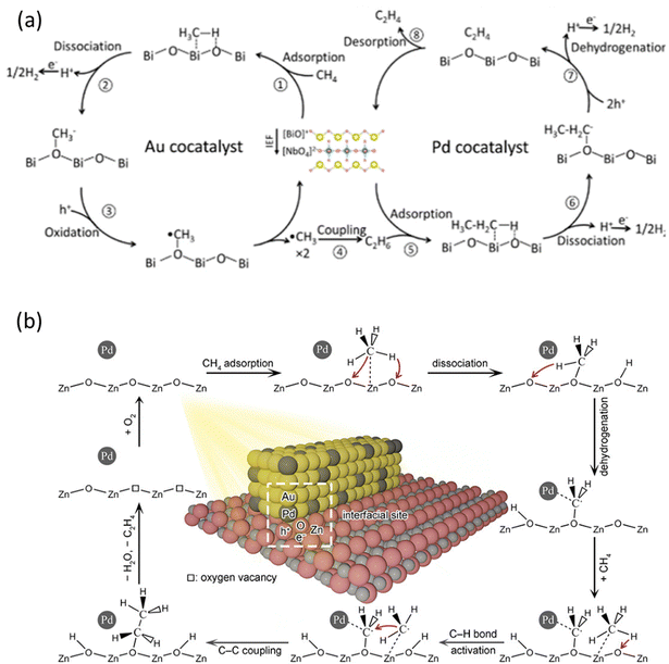 | ||
| Fig. 14 Schematic representation of photocatalytic NOCM to C2H4 reaction mechanisms over (a) Au-Pd/BiNbO5F; Reproduced with permission.76 Copyright 2023, American Chemical Society. (b) AuPd/ZnO. Reproduced with permission.73 Copyright 2020, American Chemical Society. | ||
Formation of metallic nanoalloy cocatalysts can also be used to boost C2H4 production. To overcome the weak dehydrogenation capability of Au, PdAu nanoalloys were synthesized on the surface of ZnO in which the highly dispersed Pd atoms within the Au lattice played a vital role, as shown in Fig. 14b. Au can facilitate photogenerated charge carrier separation, whereas Pd can induce further dehydrogenation capability.100 The CH4 molecules were first activated on the surface of the ZnO undergoing the dissociation process forming *CH3 which would then react with lattice oxygen to form *OCH3. With the help of Pd atoms, the *OCH3 can be dehydrogenated to *CH2O, which can then react with another CH4 molecule to generate an ethoxy intermediate (*OC2H5). In the end, the *OC2H5 will be further dehydrogenated to produce C2H4 by Pd atoms. These findings suggest the interaction between Pd atoms and *OCH3 to promote the dehydrogenation process.
4.4 Reactor configuration
Rational reactor design is crucial to achieve efficient and selective PMC activity and selectivity.101 Batch and flow reactors are two main types of photoreactors, as shown in Fig. 15a and b, respectively. In the batch reaction system, methane and/or oxidants are introduced into a sealed reactor where the photocatalyst is present. As the reaction progresses, the products generated cannot be promptly removed, leading to overoxidation to CO2. Given that the free energy of the methane coupling products is generally lower than that of methane itself,102 achieving thermodynamically favourable conditions to desired products with high yield and selectivity presents a formidable challenge within the confines of a batch reactor.17 Furthermore, mass transfer limitations are observed in gas-solid reactions within batch reactors.103 To overcome the limitations, two strategies have been introduced, i.e., circulation process and increasing the pressure of the system. The circulation process utilizes a pump to improve the mass transfer and ensures a homogeneously mixed gas environment. Increasing the pressure of the system can enhance the interaction between methane and the photocatalysts. According to Le Chatelier's principle, the reaction will shift towards decreasing the amount of gas (i.e., CH4 coupling) when the reactor pressure increases. For example, using CO2 as a mild oxidant, Ag/TiO2 achieved a high C2H4 production rate of 686 μmol g−1 h−1 under high pressure (i.e., 2 MPa).77 This indicates the significant impact of pressure increase.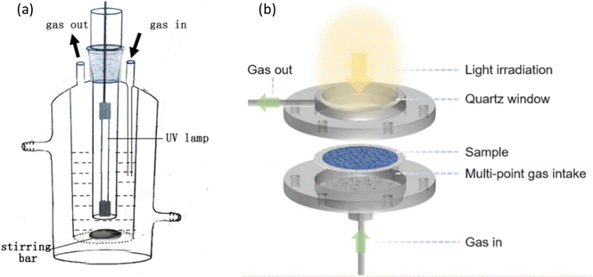 | ||
| Fig. 15 Schematic representation of photocatalytic methane conversion in (a) batch reactor; reproduced with permission.71 Copyright 2016, Elsevier. (b) Flow reactor. Reproduced with permission.104 Copyright 2024, American Chemical Society. | ||
On the other hand, flow reactors provide certain advantages over batch reactors as they improve mass transfer and enable adjustments in residence time and molecule–catalyst interactions, affording precise control over the interactions between methane and photocatalysts.75 With the timely removal of the products, the overoxidation reaction is suppressed. The single-run conversion rate assessment stands out as a particularly valuable reference for further applications.17 Notably, a flow system provides a more uniform dispersion of methane and other reactant molecules than batch reactors.104 Given these intrinsic advantages, assessing photocatalytic activity of methane coupling is critical. In an example of flow reactor utilization in photocatalytic OCM reaction, the Au–ZnO/TiO2 hybrid photocatalyst was employed.75 Compared with its performance under batch reaction, the C2 product selectivity was significantly enhanced under flow reaction. The rapid flow conditions lead to the migration of methyl radicals for coupling, which prevents photogenerated holes from oxidizing them further and reduces the yield of unwanted byproducts (e.g., coke, CO and CO2).17 Compared to the batch reaction system, these combined results highlight the advantages of a flow reaction system.
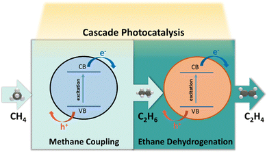
4.5 Photocatalytic CH4–C2H6–C2H4 system
Most of the aforementioned photocatalysts applied in photocatalytic methane coupling reactions present a pronounced tendency to yield C2H6 as the primary product, while the production of C2H4 plays a minor role. Attaining high selectivity towards C2H4 from photocatalytic CH4 coupling is still a challenging endeavor. Presently, industrial synthesis of C2H4 involves steam cracking, utilizing C2H6 as the principal feedstock. Drawing inspiration from this conventional industrial process, a cascade photocatalytic system denoted as the photocatalytic CH4–C2H6–C2H4 system is suggested to be implemented (Fig. 16). The photocatalytic dehydrogenation of C2H6 plays an important role in this system, which will be reviewed in this section. Upon light irradiation, the photogenerated holes in the semiconductor surface will attack the C–H bond in C2H6 molecules producing ethyl radicals (*C2H5) which then can be spontaneously dehydrogenated into C2H4 due to its intrinsic instability.105–107Table 3 summarizes the works on photocatalytic dehydrogenation of C2H6 to C2H4.| Photocatalyst | Cocatalyst | C2H4 production rate (μmol g−1 h−1) | C2H4 selectivity | Reaction conditions | Ref. |
|---|---|---|---|---|---|
| TiO2 (P25) | Pd | 230.5 | 95.42% | 300 W Xe lamp; 1 h; 25 mg catalyst; CO2: C2H6 = 1![[thin space (1/6-em)]](https://www.rsc.org/images/entities/char_2009.gif) : :![[thin space (1/6-em)]](https://www.rsc.org/images/entities/char_2009.gif) 1; 0.2 MPa 1; 0.2 MPa |
108 |
| TiO2 (P25) | Cu | 533.46 | 98.41% | UV lamp (CEL-HXF300); 1 h; 25 mg catalyst; Ar: C2H6 = 9![[thin space (1/6-em)]](https://www.rsc.org/images/entities/char_2009.gif) : :![[thin space (1/6-em)]](https://www.rsc.org/images/entities/char_2009.gif) 1; 0.2 MPa 1; 0.2 MPa |
109 |
| LaVO4-Ov | Pt | 275 | 96.8% | 300 W Xe lamp; 1 h; 100 mg catalysts; 150 mL pure C2H6 | 110 |
| TiO2 (P25) | Pd-Rh | 428.8 | 68.7% | 300 W Xe lamp; 1 h; 25 mg catalyst; C2H6: CO2 = 1![[thin space (1/6-em)]](https://www.rsc.org/images/entities/char_2009.gif) : :![[thin space (1/6-em)]](https://www.rsc.org/images/entities/char_2009.gif) 1; 0.2 MPa 1; 0.2 MPa |
111 |
| TiO2 (P25) | Pd | 614.9 | 94.6% | 300 W Xe lamp; 1 h; 25 mg catalyst; C2H6: CO2 = 1![[thin space (1/6-em)]](https://www.rsc.org/images/entities/char_2009.gif) : :![[thin space (1/6-em)]](https://www.rsc.org/images/entities/char_2009.gif) 1; 0.2 MPa 1; 0.2 MPa |
112 |
| Black TiO2 | Pt | 8.56 | 83.1% | 300 W Xe lamp (equipped with 400 nm cut-off filter); 4 h; 50 mg catalyst; 0.1 mmol ethane | 113 |
| ZnO | PdZn | 46.4 mmol g−1 h−1 | 92.6% | 100 W 365 nm LED lamp; 5 mg catalyst; reaction gas comprising C2H6 (5 vol% in Ar, 18 mL min−1) and O2 (1 vol% in Ar, 12 mL min−1); Flow reactor | 114 |
The first work of photocatalytic C2H6 dehydrogenation to C2H4 employed a Pd-deposited TiO2 (P25) photocatalyst using CO2 as the mild oxidant (Fig. 17a).108 This photocatalyst achieved a C2H4 production rate of 230.5 μmol g−1 h−1 with 95.42% selectivity. Pd was proved to lower the VB and CB of TiO2, increasing the oxidation ability of the photogenerated holes upon light irradiation. The role of Pd was further evidenced by another study investigating the effect of particle size.112 Furthermore, PdZn intermetallic nanoparticles supported on ZnO with the robust interface to promote C2H6 activation were recently reported with an excellent C2H4 production rate of 46.4 mmol g−1 h−1 with 92.6% C2H4 selectivity using O2 as the oxidant. These works demonstrated that photocatalytic oxidative dehydrogenation of C2H6 is a promising approach for C2H4 production from C2H6-containing feedstock.
 | ||
| Fig. 17 (a) Schematic representation of (a) photocatalytic oxidative dehydrogenation of C2H6 with CO2 over Pd/TiO2; Reproduced with permission.108 Copyright 2018, American Chemical Society and (b) photocatalytic C2H6 dehydrogenation over LaVO4-Ov; reproduced with permission.110 Copyright 2024, Elsevier. | ||
Photocatalytic non-oxidative C2H6 dehydrogenation has also been researched using Pt-deposited LaVO4 photocatalysts with rich oxygen vacancies through a dynamic synergistic effect of lattice oxygen and oxygen vacancies (Fig. 17b).110 This photocatalyst also presented excellent anti-coking ability with a C2H4 production rate of 275 μmol g−1 h−1 and 96.8% selectivity. The bimetallic system using Pd–Rh with internal electron transfer was also utilized to improve the light absorption and reactant adsorption.111 Besides, a non-noble metal based photocatalyst using Cu-deposited TiO2 (P25) was also used, producing C2H4 at a rate of 533.46 μmol g−1 h−1 with 98.41% selectivity.109 This is very promising due to not only cost-effectiveness but also the outstanding performance. Despite these achievements, the field of photocatalytic C2H6 dehydrogenation to C2H4 is still in its infancy to construct the cascade CH4–C2H6–C2H4 system via photocatalysis, particularly for non-noble metal-based cocatalyst design, which still requires exploration.
5 Conclusion and outlook
The increasing need for a scalable, one-step methane conversion process stems from environmental concerns and the growing demand for cleaner methods to utilize this abundant resource. The potential of EMC and PMC as viable techniques for the direct conversion of CH4 into useful compounds such as oxygenates and hydrocarbons has been highlighted by this review. Current research in EMC encompasses both heterogeneous and homogeneous systems, offering alternative pathways for producing a range of products, including C1–C3 alcohols and carboxylic acids. Significant advancements in this area have been discussed, particularly strategies to mitigate side reactions associated with the oxygen evolution reaction (OER) through innovative catalyst and reaction system designs. These strategies include replacing active oxygen species from the OER with other sources, such as carbonate anions, oxygen gas, or in situ generated hydroxyl radicals. Notably, the OER-assisted EMC approach stands out as a highly promising method, leveraging the unique benefits of electrocatalysis. In this context, single-atom catalysts, such as Fe and FeNi composites, represent cutting-edge advancements, though further research is needed to explore other electrocatalysts to enhance performance and efficiency.PMC has also emerged as a promising approach, harnessing sunlight as an energy source. This review revisits the significant progress in CH4 to C2H4 conversion via PMC, alongside strategies to enhance photocatalytic performance, including semiconductor catalyst design, cocatalyst loading, and reactor configuration. Addressing the remaining challenges requires continued research and innovation. Specifically, the development of low-cost, earth-abundant cocatalysts like Cu, Fe, Ni, and Co is essential to replace precious metals, making the process economically viable at an industrial scale. Additionally, the optimization of reactor configurations is crucial for improving mass transfer, light harvesting, and stability, warranting further attention in PMC research. Beyond the widely studied wide bandgap semiconductors like TiO2, WO3, and In2O3, it is required to develop visible-light responsive semiconductors. A proposed photocatalytic CH4–C2H6–C2H4 cascade system demonstrates promising performance for ethylene production, though further advancements in mass transfer, gas separation, and catalyst bed design are necessary. The field of photocatalytic methane coupling to ethylene holds significant potential for revolutionizing ethylene production through sustainable and eco-friendly methods. Continued interdisciplinary research and collaboration across chemistry, materials science, and engineering will be vital for translating these innovations into practical, real-world applications, paving the way for a greener approach to methane conversion.
Data availability
No primary research results, software or code have been included and no new data were generated or analysed as part of this review.Conflicts of interest
There are no conflicts to declare.Acknowledgements
The authors would like to acknowledge the support from the Australian Research Council through its DECRA (DE210100930), Discovery (DP200101900), Future Fellowship (FT230100251), and Laureate Fellowship (FL190100139) schemes from the faculty of Engineering, Architecture and Information Technology, the University of Queensland (UQ). J. Y. and Y. B. acknowledge scholarship support from UQ Graduate School.References
- International Energy Agency, Global Methane Tracker 2023, https://www.iea.org/reports/global-methane-tracker-2023/understanding-methane-emissions, (accessed Dec. 12th, 2023).
- O. Boucher and G. A. Folberth, Atmos. Environ., 2010, 44, 3343–3345 CrossRef.
- National Oceanic and Atmospheric Administration, Increase in atmospheric methane set another record during 2021, https://www.noaa.gov/news-release/increase-in-atmospheric-methane-set-another-record-during-2021, (accessed Jan. 5th, 2024).
- E. O. Day, Burning Coal Mine Methane, https://overshoot.footprintnetwork.org/portfolio/burning-methane/, (accessed 13th, Mar.).
- International Energy Agency, Gas Flaring, https://www.iea.org/energy-system/fossil-fuels/gas-flaring, (accessed Dec. 12th, 2023).
- International Energy Agency, Production - Natural Gas Information: Overview, (accessed Dec. 12th, 2023).
- X. Meng, X. Cui, N. P. Rajan, L. Yu, D. Deng and X. Bao, Chem., 2019, 5, 2296–2325 Search PubMed.
- V. V. Thyssen, V. B. Vilela, D. Z. de Florio, A. S. Ferlauto and F. C. Fonseca, Chem. Rev., 2022, 122, 3966–3995 CrossRef PubMed.
- C. Zhu, S. Hou, X. Hu, J. Lu, F. Chen and K. Xie, Nat. Commun., 2019, 10, 1173 CrossRef PubMed.
- J. H. Lunsford, Angew. Chem., Int. Ed. Engl., 1995, 34, 970–980 CrossRef.
- X. Wang, N. Luo and F. Wang, Chin. J. Chem., 2022, 40, 1492–1505 CrossRef CAS.
- Y. Khojasteh Salkuyeh and T. A. Adams, Energy Convers. Manage., 2015, 92, 406–420 CrossRef CAS.
- P. Ni, L. Cao, T. Zhu, G. Zhao, Y. Liu and Y. Lu, Fuel, 2022, 316, 123333 CrossRef CAS.
- X. Guo, G. Fang, G. Li, H. Ma, H. Fan, L. Yu, C. Ma, X. Wu, D. Deng, M. Wei, D. Tan, R. Si, S. Zhang, J. Li, L. Sun, Z. Tang, X. Pan and X. Bao, Science, 2014, 344, 616–619 CrossRef CAS PubMed.
- J. A. Arminio-Ravelo and M. Escudero-Escribano, Curr. Opin. Green Sustainable Chem., 2021, 30, 100489 CrossRef CAS.
- A. G. Abdelkader Mohamed, S. A. Zahra Naqviab and Y. Wang, ChemCatChem, 2021, 13, 787–805 CrossRef CAS.
- X. Li, C. Wang and J. Tang, Nat. Rev. Mater., 2022, 7, 617–632 CrossRef CAS.
- C. A. Ortiz-Bravo, C. A. Chagas and F. S. Toniolo, J. Nat. Gas Eng., 2021, 96, 104254 CrossRef CAS.
- T. M. Gur, Prog. Energy Combust. Sci., 2016, 54, 1–64 CrossRef.
- A. H. Bagherzadeh Mostaghimi, T. A. Al-Attas, M. G. Kibria and S. Siahrostami, J. Mater. Chem. A, 2020, 8, 15575 RSC.
- S. Xie, S. Lin, Q. Zhang, Z. Tian and Y. Wang, J. Energy Chem., 2018, 27, 1629–1636 CrossRef.
- M. R. A. Kishore, S. Lee and J. S. Yoo, Adv. Sci., 2023, 10, e2301912 CrossRef.
- Y. Jiang, S. Li, X. Fan and Z. Tang, Nano Res., 2023, 16, 12558–12571 CrossRef CAS.
- S. Wu, L. Wang and J. Zhang, J. Photochem. Photobiol., C, 2021, 46, 100400 CrossRef CAS.
- Research and Markets, Global Ethylene Market (By Production Capacity & Demand): Insights & Forecast with Potential Impact of COVID-19 (2023–2027), https://www.researchandmarkets.com/report/ethylene#cat-pos-1, (accessed December 28th, 2023).
- S. Yuan, Y. Li, J. Peng, Y. M. Questell-Santiago, K. Akkiraju, L. Giordano, D. J. Zheng, S. Bagi, Y. Román-Leshkov and Y. Shao-Horn, Adv. Energy Mater., 2020, 10, 2002154 CrossRef.
- A. Prajapati, R. Sartape, N. C. Kani, J. A. Gauthier and M. R. Singh, ACS Catal., 2022, 12, 14321–14329 CrossRef.
- P. Wang, R. Shi, Y. Zhao, Z. Li, J. Zhao, J. Zhao, G. I. N. Waterhouse, L.-Z. Wu and T. Zhang, Angew. Chem., Int. Ed., 2023, 62, e202304301 CrossRef PubMed.
- A. A. Latimer, A. R. Kulkarni, H. Aljama, J. H. Montoya, J. S. Yoo, C. Tsai, F. Abild-Pedersen, F. Studt and J. K. Nørskov, Nat. Mater., 2017, 16, 225–229 CrossRef.
- N. J. Gunsalus, A. Koppaka, S. H. Park, S. M. Bischof, B. G. Hashiguchi and R. A. Periana, Chem. Rev., 2017, 117, 8521–8573 CrossRef PubMed.
- A. A. Latimer, H. Aljama, A. Kakekhani, J. S. Yoo, A. Kulkarni, C. Tsai, M. Garcia-Melchor, F. Abild-Pedersen and J. K. Nørskov, Phys. Chem. Chem. Phys., 2017, 19, 3575–3581 RSC.
- J. A. Labinger and J. E. Bercaw, Nature, 2002, 417, 507–514 CrossRef CAS PubMed.
- J. Haber and E. M. Serwicka, React. Kinet. Catal. Lett., 1987, 35, 369–379 CrossRef CAS.
- Z. Guo, B. Liu, Q. Zhang, W. Deng, Y. Wang and Y. Yang, Chem. Soc. Rev., 2014, 43, 348–3524 Search PubMed.
- P. Banoth, C. Kandula and P. Kollu, Noble Metal-Free Electrocatalysts: New Trends in Electrocatalysts for Energy Applications. Volume 2, American Chemical Society, 2022, vol. 1432, ch. 1, pp. 1–37 Search PubMed.
- A. Prajapati, B. A. Collins, J. D. Goodpaster and M. R. Singh, Proc. Natl. Acad. Sci. U. S. A., 2021, 118(8), e2023233118 CrossRef CAS.
- C. Kim, H. Min, J. Kim and J. H. Moon, Energy Environ. Sci., 2023, 16, 3158–3165 RSC.
- K. Shen, S. Kumari, Y.-C. Huang, J. Jang, P. Sautet and C. G. Morales-Guio, J. Am. Chem. Soc., 2023, 145, 6927–6943 CrossRef CAS PubMed.
- N. Spinner and W. E. Mustain, J. Electrochem. Soc., 2013, 160, F1275–F1281 CrossRef CAS.
- M. Ma, B. J. Jin, P. Li, M. S. Jung, J. I. Kim, Y. Cho, S. Kim, J. H. Moon and J. H. Park, Adv. Sci., 2017, 4, 1700379 CrossRef PubMed.
- M. Ma, C. Oh, J. Kim, J. H. Moon and J. H. Park, Appl. Catal., B, 2019, 259, 118095 CrossRef.
- C. Oh, J. Kim, Y. J. Hwang, M. Ma and J. H. Park, Appl. Catal., B, 2021, 283, 119653 CrossRef CAS.
- J. Lee, J. Yang and J. H. Moon, ACS Energy Lett., 2021, 6, 893–899 CrossRef CAS.
- J. Li, L. Yao, D. Wu, J. King, S. S. C. Chuang, B. Liu and Z. Peng, Appl. Catal., B, 2022, 316, 121657 CrossRef CAS.
- Y. Song, Y. Zhao, G. Nan, W. Chen, Z. Guo, S. Li, Z. Tang, W. Wei and Y. Sun, Appl. Catal., B, 2020, 270, 118888 CrossRef CAS.
- Z. Xie, M. Chen, Y. Chen, A. Guan, Q. Han and G. Zheng, J. Phys. Chem. C, 2021, 125, 13324–13330 CrossRef CAS.
- M. Chen, X. Lv, A. Guan, C. Peng, L. Qian and G. Zheng, J. Colloid Interface Sci., 2022, 623, 348–353 CrossRef CAS.
- J. Kim, J. H. Kim, C. Oh, H. Yun, E. Lee, H. S. Oh, J. H. Park and Y. J. Hwang, Nat. Commun., 2023, 14, 4704 CrossRef CAS.
- Y. Song, X. Yang, H. Liu, S. Liang, Y. Cai, W. Yang, K. Zhu, L. Yu, X. Cui and D. Deng, J. Am. Chem. Soc., 2024, 146, 5834–5842 CrossRef CAS PubMed.
- M. E. O’Reilly, R. S. Kim, S. Oh and Y. Surendranath, ACS Cent. Sci., 2017, 3, 1174–1179 CrossRef PubMed.
- B. S. Natinsky, S. Lu, E. D. Copeland, J. C. Quintana and C. Liu, ACS Cent. Sci., 2019, 5, 1584–1590 CrossRef CAS.
- J. Deng, S.-C. Lin, J. Fuller, J. A. Iñiguez, D. Xiang, D. Yang, G. Chan, H. M. Chen, A. N. Alexandrova and C. Liu, Nat. Commun., 2020, 11, 3686 CrossRef PubMed.
- D. Xiang, J. A. Iñiguez, J. Deng, X. Guan, A. Martinez and C. Liu, Angew. Chem., Int. Ed., 2021, 133, 18300–18309 CrossRef.
- A. Tomita, J. Nakajima and T. Hibino, Angew. Chem., Int. Ed., 2008, 120, 1484–1486 CrossRef.
- B. Lee and T. Hibino, J. Catal., 2011, 279, 233–240 CrossRef.
- J. K. Edwards, B. Solsona, A. F. Carley, A. A. Herzing, C. J. Kiely and G. J. Hutchings, Science, 2009, 323, 1037–1041 CrossRef PubMed.
- B. Lee, Y. Sakamoto, D. Hirabayashi, K. Suzuki and T. Hibino, J. Catal., 2010, 271, 195–200 CrossRef.
- L. Chen, B. Yang, X. Zhang, W. Dong, K. Cao and X. Zhang, Energy Fuels, 2006, 20, 915–918 CrossRef CAS.
- S. Y. Chen and D. Willcox, Ind. Eng. Chem. Res., 1993, 32, 584–587 CrossRef CAS.
- A. Ruiz Puigdollers, P. Schlexer, S. Tosoni and G. Pacchioni, ACS Catal., 2017, 7, 6493–6513 CrossRef CAS.
- X.-Y. Lin, J.-Y. Li, M.-Y. Qi, Z.-R. Tang and Y.-J. Xu, Catal. Commun., 2021, 159, 106346 CrossRef CAS.
- H. Song and J. Ye, Trends Chem., 2022, 4, 1094–1105 CrossRef.
- Z. Zhu, W. Guo, Y. Zhang, C. Pan, J. Xu, Y. Zhu and Y. Lou, Carbon Energy, 2021, 3, 519–540 CrossRef.
- S. Liu, S. Udyavara, C. Zhang, M. Peter, T. L. Lohr, V. P. Dravid, M. Neurock and T. J. Marks, Proc. Natl. Acad. Sci. U. S. A., 2021, 118, e2012666118 CrossRef.
- H. Song, X. Meng, Z.-J. Wang, H. Liu and J. Ye, Joule, 2019, 3, 1606–1636 CrossRef.
- L. Yuliati, T. Hattori, H. Itoh and H. Yoshida, J. Catal., 2008, 257, 396–402 CrossRef.
- L. Yuliati, T. Hamajima, T. Hattori and H. Yoshida, J. Phys. Chem. C, 2008, 112, 7223–7232 CrossRef CAS.
- L. Li, Y.-Y. Cai, G.-D. Li, X.-Y. Mu, K.-X. Wang and J.-S. Chen, Angew. Chem., Int. Ed., 2012, 51, 4702–4706 CrossRef CAS PubMed.
- J. Xue, J. Li, Z. Sun, H. Li, H. Chang, X. Liu, H. Jia, Q. Li and Q. Shen, J. Adv. Ceram., 2023, 12, 1577–1592 CrossRef CAS.
- M. Xiao, L. Wang, H. Wang, J. Yuan, X. Chen, Z. Zhang, X. Fu and W. Dai, Catal. Sci. Technol., 2023, 13, 4148–4155 RSC.
- L. Yu, Y. Shao and D. Li, Appl. Catal., B, 2017, 204, 216–223 CrossRef CAS.
- X. Li, J. Xie, H. Rao, C. Wang and J. Tang, Angew. Chem., Int. Ed., 2020, 59, 19702–19707 CrossRef PubMed.
- W. Jiang, J. Low, K. Mao, D. Duan, S. Chen, W. Liu, C.-W. Pao, J. Ma, S. Sang, C. Shu, X. Zhan, Z. Qi, H. Zhang, Z. Liu, X. Wu, R. Long, L. Song and Y. Xiong, J. Am. Chem. Soc., 2021, 143, 269–278 CrossRef PubMed.
- Y. Liu, Y. Chen, W. Jiang, T. Kong, P. H. C. Camargo, C. Gao and Y. Xiong, Research, 2022, 2022, 9831340 Search PubMed.
- S. Song, H. Song, L. Li, S. Wang, W. Chu, K. Peng, X. Meng, Q. Wang, B. Deng, Q. Liu, Z. Wang, Y. Weng, H. Hu, H. Lin, T. Kako and J. Ye, Nat. Catal., 2021, 4, 1032–1042 CrossRef.
- C. Tang, S. Du, H. Huang, S. Tan, J. Zhao, H. Zhang, W. Ni, X. Yue, Z. Ding, Z. Zhang, R. Yuan, W. Dai, X. Fu, M. B. J. Roeffaers and J. Long, ACS Catal., 2023, 13, 6683–6689 CrossRef.
- N. Li, R. Jiang, Y. Li, J. Zhou, Q. Ma, S. Shen and M. Liu, ACS Sustainable Chem. Eng., 2019, 7, 11455–11463 CrossRef CAS.
- X. Li, C. Wang, J. Yang, Y. Xu, Y. Yang, J. Yu, J. J. Delgado, N. Martsinovich, X. Sun, X.-S. Zheng, W. Huang and J. Tang, Nat. Commun., 2023, 14, 6343 CrossRef CAS.
- X. Li, C. Li, Y. Xu, Q. Liu, M. Bahri, L. Zhang, N. D. Browning, A. J. Cowan and J. Tang, Nat. Energy, 2023, 8, 1013–1022 CrossRef CAS.
- J. Wang, Y. Peng and W. Xiao, Sci. China: Chem., 2023, 66, 3252–3261 CrossRef CAS.
- X. Chen, Y. Li, X. Pan, D. Cortie, X. Huang and Z. Yi, Nat. Commun., 2016, 7, 12273 CrossRef CAS PubMed.
- J. Xie, Y. Jiang, S. Li, P. Xu, Q. Zheng, X. Fan, H. Peng and Z. Tang, Acta Phys. -Chim. Sin., 2023, 39, 2306037 Search PubMed.
- W. Zhang, C. Fu, J. Low, D. Duan, J. Ma, W. Jiang, Y. Chen, H. Liu, Z. Qi, R. Long, Y. Yao, X. Li, H. Zhang, Z. Liu, J. Yang, Z. Zou and Y. Xiong, Nat. Commun., 2022, 13, 2806 CrossRef CAS.
- A. M. Shough, D. J. Doren and B. Ogunnaike, Chem. Mater., 2009, 21, 1232–1241 CrossRef CAS.
- S. S. Ghumro, B. Lal and T. Pirzada, ACS Omega, 2022, 7, 4333–4341 CrossRef CAS PubMed.
- J. Wang, R. Sheng, D. Gu, Y. Peng, J. Xiao, Y. Shen and W. Xiao, Chin. J. Chem., 2023, 41, 1185–1190 CrossRef CAS.
- W. Tu, W. Guo, J. Hu, H. He, H. Li, Z. Li, W. Luo, Y. Zhou and Z. Zou, Mater. Today, 2020, 33, 75–86 CrossRef CAS.
- G. Liu, J. C. Yu, G. Q. Lu and H.-M. Cheng, Chem. Commun., 2011, 47, 6763–6783 RSC.
- Y. Zhang, X. Zhi, J. R. Harmer, H. Xu, K. Davey, J. Ran and S.-Z. Qiao, Angew. Chem., Int. Ed., 2022, 61, e202212355 CrossRef CAS PubMed.
- J. Ma, R. Long, D. Liu, J. Low and Y. Xiong, Small Struct., 2022, 3, 2100147 CrossRef CAS.
- Y. Wan, J. Li, J. Ni, C. Wang, C. Ni and H. Chen, J. Hazard. Mater., 2022, 435, 129073 CrossRef CAS PubMed.
- J. Yang, D. Wang, H. Han and C. Li, Acc. Chem. Res., 2013, 46, 1900–1909 CrossRef CAS PubMed.
- J. Xie, R. Jin, A. Li, Y. Bi, Q. Ruan, Y. Deng, Y. Zhang, S. Yao, G. Sankar, D. Ma and J. Tang, Nat. Catal., 2018, 1, 889–896 CrossRef CAS.
- G. Barbillon, Phys. Chem. Chem. Phys., 2023, 25, 20178–20182 RSC.
- N. Q. Thang, A. Sabbah, L.-C. Chen, K.-H. Chen, L. V. Hai, C. M. Thi and P. V. Viet, Chem. Eng. Sci., 2021, 229, 116049 CrossRef CAS.
- A. Kudo and Y. Miseki, Chem. Soc. Rev., 2009, 38, 253–278 RSC.
- J. Oh, A. Boucly, J. A. van Bokhoven, L. Artiglia and M. Cargnello, Acc. Chem. Res., 2024, 57, 23–36 CrossRef CAS.
- A. N. Biswas, Z. Xie, R. Xia, S. Overa, F. Jiao and J. G. Chen, ACS Energy Lett., 2022, 7, 2904–2910 CrossRef.
- C. Chen, Y. Li, S. Yu, S. Louisia, J. Jin, M. Li, M. B. Ross and P. Yang, Joule, 2020, 4, 1688–1699 CrossRef.
- J. J. H. B. Sattler, J. Ruiz-Martinez, E. Santillan-Jimenez and B. M. Weckhuysen, Chem. Rev., 2014, 114, 10613–10653 CrossRef.
- A. Visan, J. R. van Ommen, M. T. Kreutzer and R. G. H. Lammertink, Ind. Eng. Chem. Res., 2019, 58, 5349–5357 CrossRef.
- R. Siriwardane, J. Riley, C. Atallah and M. Bobek, Int. J. Hydrogen Energy, 2023, 48, 14210–14225 CrossRef.
- M. D. L. M. Ballari, O. M. Alfano and A. E. Cassano, Chem. Eng. Sci., 2010, 65, 4931–4942 CrossRef CAS.
- Y. Chen, Y. Zhao, D. Liu, G. Wang, W. Jiang, S. Liu, W. Zhang, Y. Li, Z. Ma, T. Shao, H. Liu, X. Li, Z. Tang, C. Gao and Y. Xiong, J. Am. Chem. Soc., 2024, 146, 2465–2473 CrossRef CAS.
- F. Li, Y. Lai, Y. Zeng, X. Chen, T. Wang, X. Yang and Q. Guo, Chem. Sci., 2024, 15, 307–316 RSC.
- W. Guo, W. Shi, J. Cai, F. Wei, X. Lin, X. Lu, Z. Ding, Y. Hou, G. Zhang and S. Wang, Catal. Sci. Technol., 2024, 14, 2921–2928 RSC.
- R. Song, G. Zhao, J. M. Restrepo-Flórez, C. J. Viasus Pérez, Z. Chen, C. Ai, A. Wang, D. Jing, A. A. Tountas, J. Guo, C. Mao, C. Li, J. Shen, G. Cai, C. Qiu, J. Ye, Y. Fu, C. T. Maravelias, L. Wang, J. Sun, Y.-F. Xu, Z. Li, J. Y. Y. Loh, N. T. Nguyen, L. He, X. Zhang and G. A. Ozin, Nat. Energy, 2024, 9, 750–760 CrossRef CAS.
- R. Zhang, H. Wang, S. Tang, C. Liu, F. Dong, H. Yue and B. Liang, ACS Catal., 2018, 8, 9280–9286 CrossRef CAS.
- L. Song, R. Zhang, C. Zhou, G. Shu, K. Ma and H. Yue, Chem. Commun., 2023, 59, 478–481 RSC.
- F. Wei, W. Xue, Z. Yu, X. F. Lu, S. Wang, W. Lin and X. Wang, Chin. Chem. Lett., 2024, 35, 108313 CrossRef CAS.
- Q. Li, S. Tang, H. Yue, C. Liu, K. Ma, S. Zhong and B. Liang, CIESC J., 2020, 71, 3556–3564 CAS.
- Q. Li, H. Yue, C. Liu, K. Ma, S. Zhong, B. Liang and S. Tang, Chem. Eng. J., 2020, 395, 125120 CrossRef CAS.
- L. Zhang, L. Liu, Z. Pan, R. Zhang, Z. Gao, G. Wang, K. Huang, X. Mu, F. Bai, Y. Wang, W. Zhang, Z. Cui and L. Li, Nat. Energy, 2022, 7, 1042–1051 CrossRef CAS.
- P. Wang, X. Zhang, R. Shi, J. Zhao, G. I. N. Waterhouse, J. Tang and T. Zhang, Nat. Commun., 2024, 15, 789 CrossRef CAS.
Footnote |
| † J. Y. and Y. B. contributed equally to this work. |
| This journal is © The Royal Society of Chemistry 2024 |


